EP3073122B1 - Flugzeug-gasturbinentriebwerk mit verdichter und zugehöriges verfahren - Google Patents
Flugzeug-gasturbinentriebwerk mit verdichter und zugehöriges verfahren Download PDFInfo
- Publication number
- EP3073122B1 EP3073122B1 EP16160589.4A EP16160589A EP3073122B1 EP 3073122 B1 EP3073122 B1 EP 3073122B1 EP 16160589 A EP16160589 A EP 16160589A EP 3073122 B1 EP3073122 B1 EP 3073122B1
- Authority
- EP
- European Patent Office
- Prior art keywords
- component
- spool
- gas turbine
- inlet guide
- variable inlet
- Prior art date
- Legal status (The legal status is an assumption and is not a legal conclusion. Google has not performed a legal analysis and makes no representation as to the accuracy of the status listed.)
- Active
Links
Images
Classifications
-
- F—MECHANICAL ENGINEERING; LIGHTING; HEATING; WEAPONS; BLASTING
- F02—COMBUSTION ENGINES; HOT-GAS OR COMBUSTION-PRODUCT ENGINE PLANTS
- F02C—GAS-TURBINE PLANTS; AIR INTAKES FOR JET-PROPULSION PLANTS; CONTROLLING FUEL SUPPLY IN AIR-BREATHING JET-PROPULSION PLANTS
- F02C9/00—Controlling gas-turbine plants; Controlling fuel supply in air- breathing jet-propulsion plants
- F02C9/16—Control of working fluid flow
- F02C9/20—Control of working fluid flow by throttling; by adjusting vanes
-
- B—PERFORMING OPERATIONS; TRANSPORTING
- B64—AIRCRAFT; AVIATION; COSMONAUTICS
- B64C—AEROPLANES; HELICOPTERS
- B64C11/00—Propellers, e.g. of ducted type; Features common to propellers and rotors for rotorcraft
- B64C11/30—Blade pitch-changing mechanisms
- B64C11/305—Blade pitch-changing mechanisms characterised by being influenced by other control systems, e.g. fuel supply
-
- F—MECHANICAL ENGINEERING; LIGHTING; HEATING; WEAPONS; BLASTING
- F02—COMBUSTION ENGINES; HOT-GAS OR COMBUSTION-PRODUCT ENGINE PLANTS
- F02C—GAS-TURBINE PLANTS; AIR INTAKES FOR JET-PROPULSION PLANTS; CONTROLLING FUEL SUPPLY IN AIR-BREATHING JET-PROPULSION PLANTS
- F02C7/00—Features, components parts, details or accessories, not provided for in, or of interest apart form groups F02C1/00 - F02C6/00; Air intakes for jet-propulsion plants
- F02C7/04—Air intakes for gas-turbine plants or jet-propulsion plants
- F02C7/042—Air intakes for gas-turbine plants or jet-propulsion plants having variable geometry
-
- F—MECHANICAL ENGINEERING; LIGHTING; HEATING; WEAPONS; BLASTING
- F02—COMBUSTION ENGINES; HOT-GAS OR COMBUSTION-PRODUCT ENGINE PLANTS
- F02C—GAS-TURBINE PLANTS; AIR INTAKES FOR JET-PROPULSION PLANTS; CONTROLLING FUEL SUPPLY IN AIR-BREATHING JET-PROPULSION PLANTS
- F02C7/00—Features, components parts, details or accessories, not provided for in, or of interest apart form groups F02C1/00 - F02C6/00; Air intakes for jet-propulsion plants
- F02C7/26—Starting; Ignition
- F02C7/262—Restarting after flame-out
-
- F—MECHANICAL ENGINEERING; LIGHTING; HEATING; WEAPONS; BLASTING
- F02—COMBUSTION ENGINES; HOT-GAS OR COMBUSTION-PRODUCT ENGINE PLANTS
- F02C—GAS-TURBINE PLANTS; AIR INTAKES FOR JET-PROPULSION PLANTS; CONTROLLING FUEL SUPPLY IN AIR-BREATHING JET-PROPULSION PLANTS
- F02C9/00—Controlling gas-turbine plants; Controlling fuel supply in air- breathing jet-propulsion plants
- F02C9/48—Control of fuel supply conjointly with another control of the plant
- F02C9/50—Control of fuel supply conjointly with another control of the plant with control of working fluid flow
- F02C9/54—Control of fuel supply conjointly with another control of the plant with control of working fluid flow by throttling the working fluid, by adjusting vanes
-
- F—MECHANICAL ENGINEERING; LIGHTING; HEATING; WEAPONS; BLASTING
- F04—POSITIVE - DISPLACEMENT MACHINES FOR LIQUIDS; PUMPS FOR LIQUIDS OR ELASTIC FLUIDS
- F04D—NON-POSITIVE-DISPLACEMENT PUMPS
- F04D27/00—Control, e.g. regulation, of pumps, pumping installations or pumping systems specially adapted for elastic fluids
- F04D27/02—Surge control
- F04D27/0246—Surge control by varying geometry within the pumps, e.g. by adjusting vanes
-
- F—MECHANICAL ENGINEERING; LIGHTING; HEATING; WEAPONS; BLASTING
- F04—POSITIVE - DISPLACEMENT MACHINES FOR LIQUIDS; PUMPS FOR LIQUIDS OR ELASTIC FLUIDS
- F04D—NON-POSITIVE-DISPLACEMENT PUMPS
- F04D29/00—Details, component parts, or accessories
- F04D29/26—Rotors specially for elastic fluids
- F04D29/32—Rotors specially for elastic fluids for axial flow pumps
- F04D29/321—Rotors specially for elastic fluids for axial flow pumps for axial flow compressors
-
- F—MECHANICAL ENGINEERING; LIGHTING; HEATING; WEAPONS; BLASTING
- F04—POSITIVE - DISPLACEMENT MACHINES FOR LIQUIDS; PUMPS FOR LIQUIDS OR ELASTIC FLUIDS
- F04D—NON-POSITIVE-DISPLACEMENT PUMPS
- F04D29/00—Details, component parts, or accessories
- F04D29/40—Casings; Connections of working fluid
- F04D29/52—Casings; Connections of working fluid for axial pumps
- F04D29/54—Fluid-guiding means, e.g. diffusers
- F04D29/541—Specially adapted for elastic fluid pumps
- F04D29/542—Bladed diffusers
-
- F—MECHANICAL ENGINEERING; LIGHTING; HEATING; WEAPONS; BLASTING
- F04—POSITIVE - DISPLACEMENT MACHINES FOR LIQUIDS; PUMPS FOR LIQUIDS OR ELASTIC FLUIDS
- F04D—NON-POSITIVE-DISPLACEMENT PUMPS
- F04D29/00—Details, component parts, or accessories
- F04D29/40—Casings; Connections of working fluid
- F04D29/52—Casings; Connections of working fluid for axial pumps
- F04D29/54—Fluid-guiding means, e.g. diffusers
- F04D29/56—Fluid-guiding means, e.g. diffusers adjustable
- F04D29/563—Fluid-guiding means, e.g. diffusers adjustable specially adapted for elastic fluid pumps
-
- F—MECHANICAL ENGINEERING; LIGHTING; HEATING; WEAPONS; BLASTING
- F05—INDEXING SCHEMES RELATING TO ENGINES OR PUMPS IN VARIOUS SUBCLASSES OF CLASSES F01-F04
- F05D—INDEXING SCHEME FOR ASPECTS RELATING TO NON-POSITIVE-DISPLACEMENT MACHINES OR ENGINES, GAS-TURBINES OR JET-PROPULSION PLANTS
- F05D2220/00—Application
- F05D2220/30—Application in turbines
- F05D2220/32—Application in turbines in gas turbines
- F05D2220/321—Application in turbines in gas turbines for a special turbine stage
- F05D2220/3216—Application in turbines in gas turbines for a special turbine stage for a special compressor stage
-
- F—MECHANICAL ENGINEERING; LIGHTING; HEATING; WEAPONS; BLASTING
- F05—INDEXING SCHEMES RELATING TO ENGINES OR PUMPS IN VARIOUS SUBCLASSES OF CLASSES F01-F04
- F05D—INDEXING SCHEME FOR ASPECTS RELATING TO NON-POSITIVE-DISPLACEMENT MACHINES OR ENGINES, GAS-TURBINES OR JET-PROPULSION PLANTS
- F05D2220/00—Application
- F05D2220/30—Application in turbines
- F05D2220/32—Application in turbines in gas turbines
- F05D2220/323—Application in turbines in gas turbines for aircraft propulsion, e.g. jet engines
-
- F—MECHANICAL ENGINEERING; LIGHTING; HEATING; WEAPONS; BLASTING
- F05—INDEXING SCHEMES RELATING TO ENGINES OR PUMPS IN VARIOUS SUBCLASSES OF CLASSES F01-F04
- F05D—INDEXING SCHEME FOR ASPECTS RELATING TO NON-POSITIVE-DISPLACEMENT MACHINES OR ENGINES, GAS-TURBINES OR JET-PROPULSION PLANTS
- F05D2240/00—Components
- F05D2240/10—Stators
- F05D2240/12—Fluid guiding means, e.g. vanes
-
- F—MECHANICAL ENGINEERING; LIGHTING; HEATING; WEAPONS; BLASTING
- F05—INDEXING SCHEMES RELATING TO ENGINES OR PUMPS IN VARIOUS SUBCLASSES OF CLASSES F01-F04
- F05D—INDEXING SCHEME FOR ASPECTS RELATING TO NON-POSITIVE-DISPLACEMENT MACHINES OR ENGINES, GAS-TURBINES OR JET-PROPULSION PLANTS
- F05D2260/00—Function
- F05D2260/85—Starting
-
- F—MECHANICAL ENGINEERING; LIGHTING; HEATING; WEAPONS; BLASTING
- F05—INDEXING SCHEMES RELATING TO ENGINES OR PUMPS IN VARIOUS SUBCLASSES OF CLASSES F01-F04
- F05D—INDEXING SCHEME FOR ASPECTS RELATING TO NON-POSITIVE-DISPLACEMENT MACHINES OR ENGINES, GAS-TURBINES OR JET-PROPULSION PLANTS
- F05D2270/00—Control
- F05D2270/01—Purpose of the control system
- F05D2270/09—Purpose of the control system to cope with emergencies
- F05D2270/092—Purpose of the control system to cope with emergencies in particular blow-out and relight
-
- F—MECHANICAL ENGINEERING; LIGHTING; HEATING; WEAPONS; BLASTING
- F05—INDEXING SCHEMES RELATING TO ENGINES OR PUMPS IN VARIOUS SUBCLASSES OF CLASSES F01-F04
- F05D—INDEXING SCHEME FOR ASPECTS RELATING TO NON-POSITIVE-DISPLACEMENT MACHINES OR ENGINES, GAS-TURBINES OR JET-PROPULSION PLANTS
- F05D2270/00—Control
- F05D2270/30—Control parameters, e.g. input parameters
- F05D2270/304—Spool rotational speed
Definitions
- the present disclosure concerns aero gas turbine engines. More specifically the disclosure concerns aero gas turbine engines with particular variable inlet guide vane scheduling and methods of conducting an in-flight start procedure for a windmilling aero gas turbine engine.
- a windmill restart is typically attempted.
- This uses on-rushing air through which the aircraft is passing to windmill the compressors and deliver air to the combustor.
- a sufficient quantity of fuel must also be delivered to the combustor in order for successful ignition.
- Fuel is typically pumped to the combustors by a fuel pump driven by a spool powered ancillary gearbox. Under certain flight conditions the windmilling effect of the on-rushing air may turn the relevant spool at a sufficient rate in order to pump sufficient fuel to the combustor for successful start.
- the problem may be made worse where fuel is used as a process fluid in other systems, e.g. turbine case cooling, as this may increase the quantity of fuel 'leaked' to other systems (rather than to the combustor) and reduce spare capacity of the fuel pump. Solutions such as increasing pump capacity and/or other structural changes such as valves for selective isolation of systems using the fuel as a process fluid may be costly and add complexity.
- WO2013115994 discloses a gas turbine engine which includes a variable inlet guide vane positioned forwardly of a low pressure compressor. The angle of the inlet guide vane is controlled at startup to increase airflow into the compressor. This is particularly useful when the gas turbine engine is being restarted while an associated aircraft is in the air, and is relied upon to increase windmill speed of the compressor and turbine rotors. A method and nozzle are also disclosed. According to a first aspect of the invention there is provided an aero gas turbine engine according to claim 1.
- the rate of rotation of the compressor may be increased.
- a spool of the compressor with increased rate of rotation drives a fuel pump (e.g. via an ancillary gearbox)
- the fuel pump may pump more fuel, potentially increasing the size of an in-flight windmill start envelope.
- the disclosure may permit a similarly sized in-flight start envelope with use of a smaller capacity fuel pump.
- the disclosure concerns an alteration to the scheduling of the variable inlet guide vanes, it may not require structural alterations and may be implementable solely with an alteration in computer programming. Such an implementation may simplify retrofitting of the system and may mean that additional mechanical complexity and weight is not required. As will be appreciated, where engine start is referred to, this should be interpreted to include activities leading up to ignition, ignition itself and initial spool-up of the engine thereafter rather than just the instant of ignition.
- the scheduling components may take any suitable form, e.g. each could be schedules in their own right, or they could be biases selectively applicable to another schedule such as a nominal schedule.
- the controller may comprise at least one processor and at least one memory.
- the memory stores a computer program comprising computer readable instructions that, when read by the processor, cause the control described. These computer readable instructions may be, or may include the or each schedule component and/or schedule.
- the processor may be located on the gas turbine engine, or may be located remote from the gas turbine engine, or may be distributed between the gas turbine engine and a location remote from the gas turbine engine.
- the memory may be located on the gas turbine engine, or may be located remote from the gas turbine engine, or may be distributed between the gas turbine engine and a location remote from the gas turbine engine.
- each of the first and second components are invoked over a range of spool speeds for the spool encompassing ignition and initial acceleration of the engine.
- an engine start and acceleration procedure may benefit from alternative variable inlet guide vane scheduling to scheduling used in normal 'steady-state' operation of the engine, even at similarly low spool speeds.
- Each schedule component demands a particular variable inlet guide vane angle for a particular spool speed.
- a portion of a schedule component corresponds to a particular range of spool speeds within a broader range of spool speeds addressed by the schedule component.
- a part of a start procedure may be considered to correspond to a particular range of spool speeds.
- the first and second components are invoked over a range of common spool speeds. Indeed it may be that each of the first and second components are invoked over the same range of spool speeds. Thus the increase in variable inlet guide vane angle demanded by the second component by comparison with the first component may occur over a corresponding range of spool speeds. Despite the similar spool speeds the second component may therefore be used to differentiate for the specific circumstances of an in-flight windmill start.
- variable inlet guide vane angle required by the second component is consistently at least as high as the angle required by the first component over corresponding spool speeds.
- the second component requires an increased variable inlet guide vane angle by comparison with the first component at spool speeds below a particular spool speed. Additionally or alternatively the second component requires an increased variable inlet guide vane angle by comparison with the first component at spool speeds below between 10% and 20% of maximum rated spool speed and preferably at substantially 15% of maximum rated spool speed. Additionally or alternatively the second component requires an increased variable inlet guide vane angle by comparison with the first component at spool speeds below ignition.
- the maximum variable inlet guide vane angle difference required by the first component by comparison with the second component at corresponding spool speeds is between 5° and 20° and preferably between 10° and 15°.
- the first and second components require the same variable inlet guide vane angle at spool speeds above a particular spool speed. Additionally or alternatively the first and second components require the same variable inlet guide vane angle at spool speeds above between 10% and 20% of maximum rated spool speed and preferably at substantially 15% of maximum rated spool speed. Additionally or alternatively the first and second components require the same variable inlet guide vane angle at spool speeds above ignition.
- first and second components require the same variable inlet guide vane angle they may be combined into a single start component of the scheduling e.g. a single start component comprises the relevant portions of the first and second components.
- the scheduling further comprises a nominal component invoked after whichever of the first and second components is invoked for engine start.
- the nominal component may be optimised for post start operation of the variable inlet guide vanes. Specifically the nominal component may address compressor stability, particularly at engine low power settings and during transient operation. Further the nominal component may enhance steady state efficiency e.g. at cruise.
- the first and/or second components may be manifested as a variable inlet guide vane angle bias applied to the nominal component.
- the nominal component requires a decreased variable inlet guide vane angle at spool speeds above a particular spool speed.
- the nominal component comprises variable inlet guide vane scheduling for spool speeds corresponding to spool speeds over which the first and/or second components are operational when invoked.
- the nominal component may determine variable inlet guide vane scheduling at relatively low spool speeds not associated with engine start including initial acceleration.
- the first component requires a lower variable inlet guide vane angle than the nominal component over corresponding spool speeds.
- the decrease in angle demanded by the first component when invoked may be beneficial in preventing rotating stall drop-out pre-fuel on conditions and/or improving stall margin for engine ignition and initial acceleration.
- variable inlet guide vane angle required by the second component is the same as the angle required by the nominal component over part of the portion of the second component that requires a greater angle than the first component.
- the second component might therefore be considered to override the first component in the event of at least some in-flight windmill engine starts, prioritising spool speed and coincidentally following the nominal component over a relevant range of spool speeds.
- the spool of the compressor drives a fuel pump of the engine. Further the drive provided by the relevant spool may be provided indirectly e.g. via an ancillary gearbox.
- the compressor is an intermediate pressure compressor. Nonetheless in other embodiments the compressor may be a high pressure compressor.
- the method may be invoked only in accordance with particular conditions having been met. It may be for example that the method is invoked where the altitude of an aircraft powered by the engine is below a pre-determined level. Additionally or alternatively the method is invoked when the airspeed of the aircraft is below a predetermined level. Additionally or alternatively it may be that the method is invoked where the engine is outside of an operational envelope for start using a scheduling component suitable for engine ground start. Additionally or alternatively the method may be invoked only after a predetermined number of failed engine in-flight windmill start attempts. As will be appreciated, where the method is not invoked, but engine in-flight windmill start is desired, the scheduling component suitable for engine ground start may be invoked.
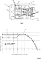
- an aero gas turbine engine is generally indicated at 10, having a principal and rotational axis 11.
- the engine 10 comprises, in axial flow series, an air intake 12, a propulsive fan 13, an array of variable inlet guide vanes 13a, an intermediate pressure compressor 14, a high-pressure compressor 15, combustion equipment 16, a high-pressure turbine 17, and intermediate pressure turbine 18, a low-pressure turbine 19 and an exhaust nozzle 20.
- a nacelle 21 generally surrounds the engine 10 and defines both the intake 12 and the exhaust nozzle 20.
- the gas turbine engine 10 works in the conventional manner so that air entering the intake 12 is accelerated by the fan 13 to produce two air flows: a first air flow into the intermediate pressure compressor 14 and a second air flow which passes through a bypass duct 22 to provide propulsive thrust.
- the intermediate pressure compressor 14 compresses the airflow directed into it before delivering that air to the high pressure compressor 15 where further compression takes place.
- the compressed air exhausted from the high-pressure compressor 15 is directed into the combustion equipment 16 where it is mixed with fuel and the mixture combusted.
- the resultant hot combustion products then expand through, and thereby drive the high, intermediate and low-pressure turbines 17, 18, 19 before being exhausted through the nozzle 20 to provide additional propulsive thrust.
- the high 17, intermediate 18 and low 19 pressure turbines drive respectively the high pressure compressor 15, intermediate pressure compressor 14 and fan 13, each by suitable interconnecting shaft.
- the intermediate pressure compressor 14 intermediate pressure turbine 18 and intermediate interconnecting shaft form an intermediate pressure spool. In use the intermediate pressure spool drives a fuel pump (not shown) via an ancillary gearbox (not shown) for delivering fuel to the combustion equipment 16.
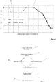
- the scheduling has a first component 30 invoked for engine ground start, a second component 32 invokable for engine in-flight windmill start and a nominal component 34 invoked after whichever of the first 30 and second 32 components is used for start of the engine.
- first component 30 invoked for engine ground start
- second component 32 invokable for engine in-flight windmill start
- nominal component 34 invoked after whichever of the first 30 and second 32 components is used for start of the engine.
- the nominal component 34 of the scheduling requires a high (maximum possible) variable inlet guide vane angle from an intermediate pressure spool speed of 0% rated maximum through approximately 60% rated maximum. As intermediate pressure spool speed increases beyond this the nominal component 34 demands a substantially steady decrease in variable inlet guide vane angle up to approximately 95% rated maximum. From approximately 95% rated maximum to 100% rated maximum the variable inlet guide vane angle required is a consistent small angle (minimum possible).
- the first component 30 of the scheduling is invokable only for intermediate pressure spool speeds between 0% and approximately 45% of rated maximum. Between 0% and substantially 40% it requires a consistent variable inlet guide vane angle smaller than the requirement of the nominal component 34 at corresponding intermediate pressure spool speeds, though nonetheless at a relatively high angle (approximately three quarters of maximum closed position). At intermediate pressure spool speeds increasing from substantially 40% to substantially 45% of the rated maximum, the first component 30 requires a consistently increasing variable inlet guide vane angle rising to the same angle requirement as the nominal component 34 at substantially 45%.
- the second component 32 of the scheduling is invokable only for intermediate pressure spool speeds between 0% and approximately 45% of rated maximum. Between 0% and substantially 10% it requires a consistent variable inlet guide vane angle consistent with the requirement of the nominal component 34 at corresponding intermediate pressure spool speeds (maximum possible). At intermediate pressure spool speeds increasing from substantially 10% to substantially 15% of the rated maximum, the second component 32 requires a consistently decreasing variable inlet guide vane angle, falling to a consistently required angle (approximately three quarters of maximum closed position) between approximately 15% and 40%. At intermediate pressure spool speeds increasing from substantially 40% to substantially 45% of the rated maximum, the second component 32 requires a consistently increasing variable inlet guide vane angle rising to the same angle requirement as the nominal component 34 at substantially 45%.
- both the first 30 and second 32 components require a bias to the nominal component 34, to thereby reduce the angle of the variable inlet guide vanes at particular intermediate pressure spool speeds.
- first 30 and second 32 components are invoked over a range of common intermediate pressure spool speeds and indeed the same range of intermediate pressure spool speeds (in this case 0% to substantially 45% of maximum rated intermediate pressure spool speed).
- the variable inlet guide vane angle required by the second component 32 is consistently at least as high as the angle required by the first component 30 over corresponding intermediate pressure spool speeds. More specifically the angle of the variable inlet guide vanes required over a portion (0% to substantially 15% of maximum rated intermediate pressure spool speed) of the second component 32 is greater than the angle required by the first component 30 over corresponding intermediate pressure spool speeds. Further from substantially 15% to 45% of maximum rated intermediate pressure spool speed the first 30 and second 32 components require the same angle.
- the first component 30 In comparing the first component 30 with the nominal component 34, the first component 30 requires a lower variable inlet guide vane angle than the nominal component 34 over corresponding intermediate pressure spool speeds (0% to substantially 45% of maximum rated intermediate pressure spool speed).
- the second component 32 In comparing the second component 32 with the nominal component 34, the second component 32 requires a variable inlet guide vane angle that is the same as the requirement of the nominal component 34 over part (0% to approximately 10% of intermediate pressure spool maximum rated speed) of the portion of the second component 32 that requires a greater angle than the first component 30.
- scheduling is used to control the angle of the array of variable inlet guide vanes throughout the operational envelope of the aero gas turbine engine.
- the initial stages comprise turning the engine using a start system (e.g. an air starter pumping air used to turn the intermediate pressure turbine 18, or turning the intermediate pressure spool using a motor supplying drive through the auxiliary gearbox).
- a start system e.g. an air starter pumping air used to turn the intermediate pressure turbine 18, or turning the intermediate pressure spool using a motor supplying drive through the auxiliary gearbox.
- Rotation of the intermediate pressure spool turns the fuel pump, pumping fuel to the combustion equipment 16.
- fuel on and ignition is instigated and the engine can be accelerated under its own power.
- the first component 30 is invoked for control of the variable inlet guide vane angle.
- the reduced angle (more open) required by the first component 30 by comparison with the nominal component 34 reduces the likelihood of rotating stall of the intermediate pressure compressor prior to fuel on and increases the stall margin of the high pressure compressor 15 at ignition and initial acceleration.
- the nominal component 34 is invoked (at the expense of the first component 30) for continued control over the angle of the variable inlet guide vanes.
- the nominal component 34 is invoked throughout the remainder of the engine run, even when the engine is operated in a regime where the intermediate pressure spool speed is within the range in which the first component 30 is invokable.
- the scheduling required by the nominal component 34 increases stability and stall margin of the intermediate pressure compressor 14 throughout its operating regime.
- a check 42 is performed to determine whether the aircraft is above a pre-determined altitude. If the aircraft is above the predetermined altitude the first component 30 is invoked 44. Where however the aircraft is not above the predetermined altitude the second component 32 is invoked 46 in preference to the first component 30. It has been found that increasing the angle of the variable inlet guide vanes somewhat counterintuitively increases the windmill rotation rate of the intermediate pressure spool. Consequently use of the second component 32 (which requires a larger variable inlet guide vane angle than the first component 30 over an initial range of intermediate pressure spool speeds) may cause additional fuel to be pumped to the combustion equipment 16 than would otherwise be the case. This in turn may allow for successful ignition 48 even at lower aircraft altitudes. Following ignition the decrease in variable inlet guide vane angle required by the second component 32 may increase the stall margin of the high pressure compressor 15 during initial acceleration 50.
- the nominal component 34 is invoked 52 (at the expense of the second component 32) for continued control over the angle of the variable inlet guide vanes.
- the nominal component 34 is invoked throughout the remainder of the engine run, even when the engine is operated in a regime where the intermediate pressure spool speed is within the range in which the second component 32 is invokable.
- the scheduling required by the nominal component 34 increases stability and stall margin of the intermediate pressure compressor 14 throughout its operating regime.
Landscapes
- Engineering & Computer Science (AREA)
- Chemical & Material Sciences (AREA)
- Combustion & Propulsion (AREA)
- Mechanical Engineering (AREA)
- General Engineering & Computer Science (AREA)
- Physics & Mathematics (AREA)
- Fluid Mechanics (AREA)
- Geometry (AREA)
- Automation & Control Theory (AREA)
- Aviation & Aerospace Engineering (AREA)
- Structures Of Non-Positive Displacement Pumps (AREA)
- Control Of Positive-Displacement Air Blowers (AREA)
Claims (14)
- Flugzeug-Gasturbinentriebwerk (10), umfassend einen Verdichter (14, 15), der auf einer Welle bereitgestellt ist, eine Anordnung aus variablen Einlassleitschaufeln (13a) für den Verdichter (14, 15) und eine Steuerung, die konfiguriert ist, den Winkel der variablen Einlassleitschaufeln (13a) gemäß einem Programm einzustellen, wobei das Programm eine erste Komponente, die für einen Bodenstart des Triebwerks aufgerufen wird, und eine zweite Komponente, die für einen Luftkraftstart des Triebwerks im Flug mindestens unter bestimmten Flugbedingungen aufgerufen wird, umfasst, und wobei der Winkel der variablen Einlassleitschaufeln (13a), der mindestens von einem Abschnitt der zweiten Komponente entsprechend einem bestimmten Bereich von Wellengeschwindigkeiten in einem größeren Bereich von Wellengeschwindigkeiten erfordert wird, größer als der Winkel der variablen Einlassleitschaufeln (13a) ist, der von mindestens einem Teil der ersten Komponente erfordert wird, der dem bestimmten Bereich von Wellengeschwindigkeiten entspricht.
- Flugzeug-Gasturbinentriebwerk nach Anspruch 1, wobei jede der ersten und zweiten Komponenten über einen Bereich von Wellengeschwindigkeiten für die Welle aufgerufen wird, umfassend die Zündung und die Anfangsbeschleunigung des Triebwerks (10).
- Flugzeug-Gasturbinentriebwerk nach Anspruch 2, wobei die erste und die zweite Komponente über einen Bereich üblicher Wellengeschwindigkeiten aufgerufen werden.
- Flugzug-Gasturbinentriebwerk nach Anspruch 3, wobei der Winkel der variablen Einlassleitschaufel, der von der zweiten Komponente erfordert wird, kontinuierlich mindestens genauso groß ist wie der Winkel, der von der ersten Komponente über entsprechende Wellengeschwindigkeiten erforderlich wird.
- Flugzeug-Gasturbinentriebwerk nach Anspruch 3 oder Anspruch 4, wobei die zweite Komponente einen größeren Winkel der variablen Einlassleitschaufel im Vergleich zur ersten Komponente bei Wellengeschwindigkeiten unter einer bestimmten Wellengeschwindigkeit erfordert.
- Flugzeug-Gasturbinentriebwerk nach einem der Ansprüche 3 bis 5, wobei die erste und die zweite Komponente denselben Winkel der variablen Einlassleitschaufel bei Wellengeschwindigkeiten oberhalb einer bestimmten Wellengeschwindigkeit erfordern.
- Flugzeug-Gasturbinentriebwerk nach einem der Ansprüche 2 bis 6, wobei das Programmieren ferner eine nominale Komponente umfasst, die nach der jeweiligen der ersten bzw. der zweiten Komponente aufgerufen wird, welche für den Triebwerkstart aufgerufen wird.
- Flugzeug-Gasturbinenmotor nach Anspruch 7, wobei die nominale Komponente eine Programmierung der variablen Einlassleitschaufel für Wellengeschwindigkeiten umfasst, die Wellengeschwindigkeiten entsprechen, über denen die erste und/oder zweite Komponente betriebsbereit sind, wenn sie aufgerufen werden.
- Flugzeug-Gasturbinentriebwerk nach Anspruch 7 oder Anspruch 8, wobei die erste Komponente einen kleineren Winkel der variablen Einlassleitschaufel als die nominale Komponente über entsprechende Wellengeschwindigkeiten erfordert.
- Flugzeug-Gasturbinenmotor nach einem der Ansprüche 7 bis 9, wobei der von der zweiten Komponente erforderte Winkel der variablen Einlassleitschaufel derselbe ist wie der von der nominalen Komponente über einen Teil des Abschnitts der zweiten Komponente erforderte Winkel, der einen größeren Winkel als die erste Komponente erfordert.
- Flugzeug-Gasturbinentriebwerk nach einem der vorstehenden Ansprüche, wobei die Welle des Verdichters (14, 15) eine Treibstoffpumpe des Triebwerks antreibt.
- Flugzeug-Gasturbinentriebwerk (10) nach einem der vorstehenden Ansprüche, wobei der Verdichter ein Mitteldruckverdichter (14) ist.
- Verfahren zur Durchführung eines Startverfahrens im Flug zum Starten eines Flugzeug-Gasturbinentriebwerks (10) durch Luftkräfte, umfassend das Programmieren variabler Einlassleitschaufeln (13a) über mindestens einen Teil des Startverfahrens für einen Verdichter (14, 15) des Triebwerks (10), der auf einer Welle bereitgestellt ist, so dass der Winkel der variablen Einlassleitschaufeln (13a) größer ist als über mindestens einen Teil eines Triebwerkbodenstarts über einen bestimmten Bereich von Wellengeschwindigkeit in einem größeren Bereich von Wellengeschwindigkeiten programmiert.
- Verfahren nach Anspruch 13, das nur aufgerufen wird, wenn die Höhe eines durch das Triebwerk (10) versorgten Flugzeugs unterhalb einer vorbestimmten Höhe ist.
Applications Claiming Priority (1)
| Application Number | Priority Date | Filing Date | Title |
|---|---|---|---|
| GBGB1505113.9A GB201505113D0 (en) | 2015-03-26 | 2015-03-26 | Variable inlet guide vane scheduling |
Publications (2)
| Publication Number | Publication Date |
|---|---|
| EP3073122A1 EP3073122A1 (de) | 2016-09-28 |
| EP3073122B1 true EP3073122B1 (de) | 2019-09-04 |
Family
ID=53052439
Family Applications (1)
| Application Number | Title | Priority Date | Filing Date |
|---|---|---|---|
| EP16160589.4A Active EP3073122B1 (de) | 2015-03-26 | 2016-03-16 | Flugzeug-gasturbinentriebwerk mit verdichter und zugehöriges verfahren |
Country Status (3)
| Country | Link |
|---|---|
| US (1) | US10227931B2 (de) |
| EP (1) | EP3073122B1 (de) |
| GB (1) | GB201505113D0 (de) |
Families Citing this family (16)
| Publication number | Priority date | Publication date | Assignee | Title |
|---|---|---|---|---|
| US11415063B2 (en) * | 2016-09-15 | 2022-08-16 | Pratt & Whitney Canada Corp. | Reverse-flow gas turbine engine |
| US11105269B2 (en) | 2017-05-12 | 2021-08-31 | General Electric Company | Method of control of three spool gas turbine engine |
| CN108150294B (zh) * | 2017-11-29 | 2019-05-17 | 北京动力机械研究所 | 一种微型涡喷发动机变增益转速闭环控制方法 |
| EP3502438A1 (de) * | 2017-12-19 | 2019-06-26 | Siemens Aktiengesellschaft | Kompressorsteuerung |
| US11427304B2 (en) | 2018-10-15 | 2022-08-30 | Pratt & Whitney Canada Corp. | System and method for slowing down aircraft |
| US11578661B2 (en) | 2019-09-19 | 2023-02-14 | Pratt & Whitney Canada Corp. | Systems and methods for starting a gas turbine engine |
| US11554874B2 (en) * | 2020-10-02 | 2023-01-17 | Pratt & Whitney Canada Corp. | Method and system for governing an engine at low power |
| US20220106915A1 (en) * | 2020-10-05 | 2022-04-07 | Pratt & Whitney Canada Corp. | Method and system for operating a gas turbine engine to avoid restricted engine speeds |
| US11668253B2 (en) | 2020-10-16 | 2023-06-06 | Pratt & Whitney Canada Corp. | System and method for providing in-flight reverse thrust for an aircraft |
| CN112464357B (zh) * | 2020-10-27 | 2022-04-08 | 中国船舶重工集团公司第七0三研究所 | 一种船舶燃气轮机轴流压气机低工况可转导叶转角规律设计方法 |
| US11898500B2 (en) * | 2020-12-22 | 2024-02-13 | Textron Innovations Inc. | Inlet configuration enabling rapid in-flight engine restart |
| US11428160B2 (en) | 2020-12-31 | 2022-08-30 | General Electric Company | Gas turbine engine with interdigitated turbine and gear assembly |
| US12180974B2 (en) | 2022-03-24 | 2024-12-31 | Copeland Lp | Variable inlet guide vane apparatus and compressor including same |
| CN114893433B (zh) * | 2022-05-27 | 2023-07-21 | 珠海格力电器股份有限公司 | 一种混流风机、其控制方法及风管机空调 |
| US12253030B2 (en) * | 2022-07-01 | 2025-03-18 | Rtx Corporation | In-flight engine re-start |
| US12516678B2 (en) | 2023-03-20 | 2026-01-06 | Copeland Lp | Variable inlet guide vane apparatus combined with compressor end cap |
Family Cites Families (6)
| Publication number | Priority date | Publication date | Assignee | Title |
|---|---|---|---|---|
| US4275560A (en) * | 1978-12-27 | 1981-06-30 | General Electric Company | Blocker door actuation system |
| DE19901509B4 (de) * | 1999-01-16 | 2010-11-25 | Rolls-Royce Deutschland Ltd & Co Kg | Verfahren zum Verstellen der Leitschaufeln einer Strömungsarbeitsmaschine |
| US8291690B1 (en) * | 2012-01-31 | 2012-10-23 | United Technologies Corporation | Gas turbine engine with variable area fan nozzle positioned for starting |
| US20130192195A1 (en) | 2012-01-31 | 2013-08-01 | Eric J. Wehmeier | Gas turbine engine with compressor inlet guide vane positioned for starting |
| US9303565B2 (en) * | 2012-06-29 | 2016-04-05 | Solar Turbines Incorporated | Method and system for operating a turbine engine |
| US20140130513A1 (en) * | 2012-11-09 | 2014-05-15 | General Electric Company | System and method for improving gas turbine performance at part-load operation |
-
2015
- 2015-03-26 GB GBGB1505113.9A patent/GB201505113D0/en not_active Ceased
-
2016
- 2016-03-16 EP EP16160589.4A patent/EP3073122B1/de active Active
- 2016-03-21 US US15/075,919 patent/US10227931B2/en active Active
Non-Patent Citations (1)
| Title |
|---|
| None * |
Also Published As
| Publication number | Publication date |
|---|---|
| US20160281611A1 (en) | 2016-09-29 |
| GB201505113D0 (en) | 2015-05-06 |
| US10227931B2 (en) | 2019-03-12 |
| EP3073122A1 (de) | 2016-09-28 |
Similar Documents
| Publication | Publication Date | Title |
|---|---|---|
| EP3073122B1 (de) | Flugzeug-gasturbinentriebwerk mit verdichter und zugehöriges verfahren | |
| US10934972B2 (en) | Stability margin and clearance control using power extraction and assist of a gas turbine engine | |
| US20150167553A1 (en) | Systems and methods for controlling aircraft main engine speeds | |
| EP3118437B1 (de) | Brennstoffregelung eines gasturbinenmotors | |
| CN111255571A (zh) | 用于控制气体涡轮引擎的启动或重新点火过程的至少一部分的方法和装置 | |
| EP3135883B1 (de) | Antriebssystem sowie verfahren zum betrieb einer gasturbine eines antriebssystems | |
| US12170500B2 (en) | Active stability control of compression systems utilizing electric machines | |
| US12078101B2 (en) | Method for regulating a turbomachine comprising a temporary power-increasing device | |
| US20160138475A1 (en) | Method of starting a gas turbine engine | |
| EP4296493A1 (de) | Doppelbrennstoffpumpensystem für ein flugzeug | |
| EP4130451B1 (de) | Schneller motorneustart für ein mehrmotoriges system und verfahren | |
| EP3978739B1 (de) | Verfahren und system zur steuerung eines motors bei niedriger leistung | |
| EP3978741A1 (de) | Verfahren und system zum betrieb eines gasturbinentriebwerks zur vermeidung von eingeschränkten motorgeschwindigkeiten | |
| EP4484728A1 (de) | Flugzeugtriebwerk mit mehreren unabhängigen kraftstoffsystemen | |
| US20230296058A1 (en) | Systems and methods for starting a gas turbine engine | |
| CN119933863B (zh) | 航空发动机空中起动方法及系统 | |
| Laskowski | Factors influencing axial compressor stalls |
Legal Events
| Date | Code | Title | Description |
|---|---|---|---|
| PUAI | Public reference made under article 153(3) epc to a published international application that has entered the european phase |
Free format text: ORIGINAL CODE: 0009012 |
|
| AK | Designated contracting states |
Kind code of ref document: A1 Designated state(s): AL AT BE BG CH CY CZ DE DK EE ES FI FR GB GR HR HU IE IS IT LI LT LU LV MC MK MT NL NO PL PT RO RS SE SI SK SM TR |
|
| AX | Request for extension of the european patent |
Extension state: BA ME |
|
| STAA | Information on the status of an ep patent application or granted ep patent |
Free format text: STATUS: REQUEST FOR EXAMINATION WAS MADE |
|
| 17P | Request for examination filed |
Effective date: 20170210 |
|
| RBV | Designated contracting states (corrected) |
Designated state(s): AL AT BE BG CH CY CZ DE DK EE ES FI FR GB GR HR HU IE IS IT LI LT LU LV MC MK MT NL NO PL PT RO RS SE SI SK SM TR |
|
| GRAP | Despatch of communication of intention to grant a patent |
Free format text: ORIGINAL CODE: EPIDOSNIGR1 |
|
| STAA | Information on the status of an ep patent application or granted ep patent |
Free format text: STATUS: GRANT OF PATENT IS INTENDED |
|
| GRAS | Grant fee paid |
Free format text: ORIGINAL CODE: EPIDOSNIGR3 |
|
| GRAA | (expected) grant |
Free format text: ORIGINAL CODE: 0009210 |
|
| STAA | Information on the status of an ep patent application or granted ep patent |
Free format text: STATUS: THE PATENT HAS BEEN GRANTED |
|
| INTG | Intention to grant announced |
Effective date: 20190708 |
|
| AK | Designated contracting states |
Kind code of ref document: B1 Designated state(s): AL AT BE BG CH CY CZ DE DK EE ES FI FR GB GR HR HU IE IS IT LI LT LU LV MC MK MT NL NO PL PT RO RS SE SI SK SM TR |
|
| REG | Reference to a national code |
Ref country code: GB Ref legal event code: FG4D |
|
| REG | Reference to a national code |
Ref country code: CH Ref legal event code: EP |
|
| REG | Reference to a national code |
Ref country code: AT Ref legal event code: REF Ref document number: 1175728 Country of ref document: AT Kind code of ref document: T Effective date: 20190915 |
|
| REG | Reference to a national code |
Ref country code: DE Ref legal event code: R096 Ref document number: 602016019718 Country of ref document: DE |
|
| REG | Reference to a national code |
Ref country code: IE Ref legal event code: FG4D |
|
| REG | Reference to a national code |
Ref country code: NL Ref legal event code: MP Effective date: 20190904 |
|
| REG | Reference to a national code |
Ref country code: LT Ref legal event code: MG4D |
|
| PG25 | Lapsed in a contracting state [announced via postgrant information from national office to epo] |
Ref country code: LT Free format text: LAPSE BECAUSE OF FAILURE TO SUBMIT A TRANSLATION OF THE DESCRIPTION OR TO PAY THE FEE WITHIN THE PRESCRIBED TIME-LIMIT Effective date: 20190904 Ref country code: HR Free format text: LAPSE BECAUSE OF FAILURE TO SUBMIT A TRANSLATION OF THE DESCRIPTION OR TO PAY THE FEE WITHIN THE PRESCRIBED TIME-LIMIT Effective date: 20190904 Ref country code: BG Free format text: LAPSE BECAUSE OF FAILURE TO SUBMIT A TRANSLATION OF THE DESCRIPTION OR TO PAY THE FEE WITHIN THE PRESCRIBED TIME-LIMIT Effective date: 20191204 Ref country code: SE Free format text: LAPSE BECAUSE OF FAILURE TO SUBMIT A TRANSLATION OF THE DESCRIPTION OR TO PAY THE FEE WITHIN THE PRESCRIBED TIME-LIMIT Effective date: 20190904 Ref country code: NO Free format text: LAPSE BECAUSE OF FAILURE TO SUBMIT A TRANSLATION OF THE DESCRIPTION OR TO PAY THE FEE WITHIN THE PRESCRIBED TIME-LIMIT Effective date: 20191204 Ref country code: FI Free format text: LAPSE BECAUSE OF FAILURE TO SUBMIT A TRANSLATION OF THE DESCRIPTION OR TO PAY THE FEE WITHIN THE PRESCRIBED TIME-LIMIT Effective date: 20190904 |
|
| RAP2 | Party data changed (patent owner data changed or rights of a patent transferred) |
Owner name: ROLLS-ROYCE PLC |
|
| PG25 | Lapsed in a contracting state [announced via postgrant information from national office to epo] |
Ref country code: RS Free format text: LAPSE BECAUSE OF FAILURE TO SUBMIT A TRANSLATION OF THE DESCRIPTION OR TO PAY THE FEE WITHIN THE PRESCRIBED TIME-LIMIT Effective date: 20190904 Ref country code: GR Free format text: LAPSE BECAUSE OF FAILURE TO SUBMIT A TRANSLATION OF THE DESCRIPTION OR TO PAY THE FEE WITHIN THE PRESCRIBED TIME-LIMIT Effective date: 20191205 Ref country code: LV Free format text: LAPSE BECAUSE OF FAILURE TO SUBMIT A TRANSLATION OF THE DESCRIPTION OR TO PAY THE FEE WITHIN THE PRESCRIBED TIME-LIMIT Effective date: 20190904 Ref country code: AL Free format text: LAPSE BECAUSE OF FAILURE TO SUBMIT A TRANSLATION OF THE DESCRIPTION OR TO PAY THE FEE WITHIN THE PRESCRIBED TIME-LIMIT Effective date: 20190904 Ref country code: ES Free format text: LAPSE BECAUSE OF FAILURE TO SUBMIT A TRANSLATION OF THE DESCRIPTION OR TO PAY THE FEE WITHIN THE PRESCRIBED TIME-LIMIT Effective date: 20190904 |
|
| REG | Reference to a national code |
Ref country code: AT Ref legal event code: MK05 Ref document number: 1175728 Country of ref document: AT Kind code of ref document: T Effective date: 20190904 |
|
| PG25 | Lapsed in a contracting state [announced via postgrant information from national office to epo] |
Ref country code: AT Free format text: LAPSE BECAUSE OF FAILURE TO SUBMIT A TRANSLATION OF THE DESCRIPTION OR TO PAY THE FEE WITHIN THE PRESCRIBED TIME-LIMIT Effective date: 20190904 Ref country code: NL Free format text: LAPSE BECAUSE OF FAILURE TO SUBMIT A TRANSLATION OF THE DESCRIPTION OR TO PAY THE FEE WITHIN THE PRESCRIBED TIME-LIMIT Effective date: 20190904 Ref country code: PL Free format text: LAPSE BECAUSE OF FAILURE TO SUBMIT A TRANSLATION OF THE DESCRIPTION OR TO PAY THE FEE WITHIN THE PRESCRIBED TIME-LIMIT Effective date: 20190904 Ref country code: RO Free format text: LAPSE BECAUSE OF FAILURE TO SUBMIT A TRANSLATION OF THE DESCRIPTION OR TO PAY THE FEE WITHIN THE PRESCRIBED TIME-LIMIT Effective date: 20190904 Ref country code: IT Free format text: LAPSE BECAUSE OF FAILURE TO SUBMIT A TRANSLATION OF THE DESCRIPTION OR TO PAY THE FEE WITHIN THE PRESCRIBED TIME-LIMIT Effective date: 20190904 Ref country code: PT Free format text: LAPSE BECAUSE OF FAILURE TO SUBMIT A TRANSLATION OF THE DESCRIPTION OR TO PAY THE FEE WITHIN THE PRESCRIBED TIME-LIMIT Effective date: 20200106 Ref country code: EE Free format text: LAPSE BECAUSE OF FAILURE TO SUBMIT A TRANSLATION OF THE DESCRIPTION OR TO PAY THE FEE WITHIN THE PRESCRIBED TIME-LIMIT Effective date: 20190904 |
|
| PG25 | Lapsed in a contracting state [announced via postgrant information from national office to epo] |
Ref country code: SM Free format text: LAPSE BECAUSE OF FAILURE TO SUBMIT A TRANSLATION OF THE DESCRIPTION OR TO PAY THE FEE WITHIN THE PRESCRIBED TIME-LIMIT Effective date: 20190904 Ref country code: CZ Free format text: LAPSE BECAUSE OF FAILURE TO SUBMIT A TRANSLATION OF THE DESCRIPTION OR TO PAY THE FEE WITHIN THE PRESCRIBED TIME-LIMIT Effective date: 20190904 Ref country code: SK Free format text: LAPSE BECAUSE OF FAILURE TO SUBMIT A TRANSLATION OF THE DESCRIPTION OR TO PAY THE FEE WITHIN THE PRESCRIBED TIME-LIMIT Effective date: 20190904 Ref country code: IS Free format text: LAPSE BECAUSE OF FAILURE TO SUBMIT A TRANSLATION OF THE DESCRIPTION OR TO PAY THE FEE WITHIN THE PRESCRIBED TIME-LIMIT Effective date: 20200224 |
|
| REG | Reference to a national code |
Ref country code: DE Ref legal event code: R097 Ref document number: 602016019718 Country of ref document: DE |
|
| PLBE | No opposition filed within time limit |
Free format text: ORIGINAL CODE: 0009261 |
|
| STAA | Information on the status of an ep patent application or granted ep patent |
Free format text: STATUS: NO OPPOSITION FILED WITHIN TIME LIMIT |
|
| PG2D | Information on lapse in contracting state deleted |
Ref country code: IS |
|
| PG25 | Lapsed in a contracting state [announced via postgrant information from national office to epo] |
Ref country code: DK Free format text: LAPSE BECAUSE OF FAILURE TO SUBMIT A TRANSLATION OF THE DESCRIPTION OR TO PAY THE FEE WITHIN THE PRESCRIBED TIME-LIMIT Effective date: 20190904 Ref country code: IS Free format text: LAPSE BECAUSE OF FAILURE TO SUBMIT A TRANSLATION OF THE DESCRIPTION OR TO PAY THE FEE WITHIN THE PRESCRIBED TIME-LIMIT Effective date: 20200105 |
|
| 26N | No opposition filed |
Effective date: 20200605 |
|
| PG25 | Lapsed in a contracting state [announced via postgrant information from national office to epo] |
Ref country code: SI Free format text: LAPSE BECAUSE OF FAILURE TO SUBMIT A TRANSLATION OF THE DESCRIPTION OR TO PAY THE FEE WITHIN THE PRESCRIBED TIME-LIMIT Effective date: 20190904 |
|
| PG25 | Lapsed in a contracting state [announced via postgrant information from national office to epo] |
Ref country code: MC Free format text: LAPSE BECAUSE OF FAILURE TO SUBMIT A TRANSLATION OF THE DESCRIPTION OR TO PAY THE FEE WITHIN THE PRESCRIBED TIME-LIMIT Effective date: 20190904 |
|
| REG | Reference to a national code |
Ref country code: CH Ref legal event code: PL |
|
| REG | Reference to a national code |
Ref country code: BE Ref legal event code: MM Effective date: 20200331 |
|
| PG25 | Lapsed in a contracting state [announced via postgrant information from national office to epo] |
Ref country code: LU Free format text: LAPSE BECAUSE OF NON-PAYMENT OF DUE FEES Effective date: 20200316 |
|
| PG25 | Lapsed in a contracting state [announced via postgrant information from national office to epo] |
Ref country code: CH Free format text: LAPSE BECAUSE OF NON-PAYMENT OF DUE FEES Effective date: 20200331 Ref country code: LI Free format text: LAPSE BECAUSE OF NON-PAYMENT OF DUE FEES Effective date: 20200331 Ref country code: IE Free format text: LAPSE BECAUSE OF NON-PAYMENT OF DUE FEES Effective date: 20200316 |
|
| PG25 | Lapsed in a contracting state [announced via postgrant information from national office to epo] |
Ref country code: BE Free format text: LAPSE BECAUSE OF NON-PAYMENT OF DUE FEES Effective date: 20200331 |
|
| PG25 | Lapsed in a contracting state [announced via postgrant information from national office to epo] |
Ref country code: TR Free format text: LAPSE BECAUSE OF FAILURE TO SUBMIT A TRANSLATION OF THE DESCRIPTION OR TO PAY THE FEE WITHIN THE PRESCRIBED TIME-LIMIT Effective date: 20190904 Ref country code: MT Free format text: LAPSE BECAUSE OF FAILURE TO SUBMIT A TRANSLATION OF THE DESCRIPTION OR TO PAY THE FEE WITHIN THE PRESCRIBED TIME-LIMIT Effective date: 20190904 Ref country code: CY Free format text: LAPSE BECAUSE OF FAILURE TO SUBMIT A TRANSLATION OF THE DESCRIPTION OR TO PAY THE FEE WITHIN THE PRESCRIBED TIME-LIMIT Effective date: 20190904 |
|
| PG25 | Lapsed in a contracting state [announced via postgrant information from national office to epo] |
Ref country code: MK Free format text: LAPSE BECAUSE OF FAILURE TO SUBMIT A TRANSLATION OF THE DESCRIPTION OR TO PAY THE FEE WITHIN THE PRESCRIBED TIME-LIMIT Effective date: 20190904 |
|
| P01 | Opt-out of the competence of the unified patent court (upc) registered |
Effective date: 20230528 |
|
| PGFP | Annual fee paid to national office [announced via postgrant information from national office to epo] |
Ref country code: GB Payment date: 20260323 Year of fee payment: 11 |
|
| PGFP | Annual fee paid to national office [announced via postgrant information from national office to epo] |
Ref country code: DE Payment date: 20260320 Year of fee payment: 11 |
|
| PGFP | Annual fee paid to national office [announced via postgrant information from national office to epo] |
Ref country code: FR Payment date: 20260323 Year of fee payment: 11 |