EP3073145A2 - Amortisseur de chocs - Google Patents
Amortisseur de chocs Download PDFInfo
- Publication number
- EP3073145A2 EP3073145A2 EP16157281.3A EP16157281A EP3073145A2 EP 3073145 A2 EP3073145 A2 EP 3073145A2 EP 16157281 A EP16157281 A EP 16157281A EP 3073145 A2 EP3073145 A2 EP 3073145A2
- Authority
- EP
- European Patent Office
- Prior art keywords
- rod
- gas spring
- lip
- chamber
- spring chamber
- Prior art date
- Legal status (The legal status is an assumption and is not a legal conclusion. Google has not performed a legal analysis and makes no representation as to the accuracy of the status listed.)
- Granted
Links
Images


Classifications
-
- B—PERFORMING OPERATIONS; TRANSPORTING
- B62—LAND VEHICLES FOR TRAVELLING OTHERWISE THAN ON RAILS
- B62K—CYCLES; CYCLE FRAMES; CYCLE STEERING DEVICES; RIDER-OPERATED TERMINAL CONTROLS SPECIALLY ADAPTED FOR CYCLES; CYCLE AXLE SUSPENSIONS; CYCLE SIDECARS, FORECARS, OR THE LIKE
- B62K25/00—Axle suspensions
- B62K25/04—Axle suspensions for mounting axles resiliently on cycle frame or fork
- B62K25/06—Axle suspensions for mounting axles resiliently on cycle frame or fork with telescopic fork, e.g. including auxiliary rocking arms
- B62K25/08—Axle suspensions for mounting axles resiliently on cycle frame or fork with telescopic fork, e.g. including auxiliary rocking arms for front wheel
-
- F—MECHANICAL ENGINEERING; LIGHTING; HEATING; WEAPONS; BLASTING
- F16—ENGINEERING ELEMENTS AND UNITS; GENERAL MEASURES FOR PRODUCING AND MAINTAINING EFFECTIVE FUNCTIONING OF MACHINES OR INSTALLATIONS; THERMAL INSULATION IN GENERAL
- F16F—SPRINGS; SHOCK-ABSORBERS; MEANS FOR DAMPING VIBRATION
- F16F9/00—Springs, vibration-dampers, shock-absorbers, or similarly-constructed movement-dampers using a fluid or the equivalent as damping medium
- F16F9/02—Springs, vibration-dampers, shock-absorbers, or similarly-constructed movement-dampers using a fluid or the equivalent as damping medium using gas only or vacuum
- F16F9/0209—Telescopic
- F16F9/0218—Mono-tubular units
-
- F—MECHANICAL ENGINEERING; LIGHTING; HEATING; WEAPONS; BLASTING
- F16—ENGINEERING ELEMENTS AND UNITS; GENERAL MEASURES FOR PRODUCING AND MAINTAINING EFFECTIVE FUNCTIONING OF MACHINES OR INSTALLATIONS; THERMAL INSULATION IN GENERAL
- F16F—SPRINGS; SHOCK-ABSORBERS; MEANS FOR DAMPING VIBRATION
- F16F9/00—Springs, vibration-dampers, shock-absorbers, or similarly-constructed movement-dampers using a fluid or the equivalent as damping medium
- F16F9/06—Springs, vibration-dampers, shock-absorbers, or similarly-constructed movement-dampers using a fluid or the equivalent as damping medium using both gas and liquid
- F16F9/062—Bi-tubular units
-
- F—MECHANICAL ENGINEERING; LIGHTING; HEATING; WEAPONS; BLASTING
- F16—ENGINEERING ELEMENTS AND UNITS; GENERAL MEASURES FOR PRODUCING AND MAINTAINING EFFECTIVE FUNCTIONING OF MACHINES OR INSTALLATIONS; THERMAL INSULATION IN GENERAL
- F16F—SPRINGS; SHOCK-ABSORBERS; MEANS FOR DAMPING VIBRATION
- F16F9/00—Springs, vibration-dampers, shock-absorbers, or similarly-constructed movement-dampers using a fluid or the equivalent as damping medium
- F16F9/10—Springs, vibration-dampers, shock-absorbers, or similarly-constructed movement-dampers using a fluid or the equivalent as damping medium using liquid only; using a fluid of which the nature is immaterial
- F16F9/14—Devices with one or more members, e.g. pistons, vanes, moving to and fro in chambers and using throttling effect
- F16F9/16—Devices with one or more members, e.g. pistons, vanes, moving to and fro in chambers and using throttling effect involving only straight-line movement of the effective parts
- F16F9/18—Devices with one or more members, e.g. pistons, vanes, moving to and fro in chambers and using throttling effect involving only straight-line movement of the effective parts with a closed cylinder and a piston separating two or more working spaces therein
-
- F—MECHANICAL ENGINEERING; LIGHTING; HEATING; WEAPONS; BLASTING
- F16—ENGINEERING ELEMENTS AND UNITS; GENERAL MEASURES FOR PRODUCING AND MAINTAINING EFFECTIVE FUNCTIONING OF MACHINES OR INSTALLATIONS; THERMAL INSULATION IN GENERAL
- F16F—SPRINGS; SHOCK-ABSORBERS; MEANS FOR DAMPING VIBRATION
- F16F9/00—Springs, vibration-dampers, shock-absorbers, or similarly-constructed movement-dampers using a fluid or the equivalent as damping medium
- F16F9/32—Details
- F16F9/36—Special sealings, including sealings or guides for piston-rods
- F16F9/362—Combination of sealing and guide arrangements for piston rods
Definitions
- the present invention relates to a gas spring shock absorber.
- a shock absorber which is configured such that a first end of a circular cylindrical inner tube is fixed to a first end fixation portion in a sealed manner, a second end of a circular cylindrical outer tube is fixed to a second end fixation portion in a sealed manner, a second end of the inner tube is inserted into the outer tube via a first end opening of the circular cylindrical outer tube, the inner tube and the outer tube can move relative to each other along the center axis thereof in a state where air-tight sealing between an outer circumferential surface of the inner tube and an inner circumferential surface of the outer tube is formed, a circular cylinder and a circular cylindrical rod are provided inside of the outer tube and the inner tube, a first end of the rod is fixed to the first end fixation portion in such a way that a first end opening of the rod is sealed, a second end of the cylinder is fixed to the second end fixation portion in such a way that a second end opening of the cylinder is sealed, a second end of the rod is inserted into the
- the interior of the shock absorber is divided into three chambers: an inner chamber as a first gas spring chamber that is formed as a sealed space surrounded by the piston, the second end fixation portion, and an inner circumferential surface of the cylinder between the piston and the second end fixation portion; an outer chamber as a second gas spring chamber that is formed as a sealed space surrounded by an outer circumferential surface of the rod, the first end fixation portion, the inner circumferential surfaces of the inner tube and the outer tube, the second end fixation portion, and an outer circumferential surface of the cylinder; and a balance chamber as a third gas spring chamber that is formed as a sealed space surrounded by the piston, the rod guide, and the inner circumferential surface of the cylinder between the piston and the rod guide.
- This shock absorber includes a piston lip packing which is provided so as to maintain air-tight sealing between an outer circumferential surface of the piston and the inner circumferential surface of the cylinder such that air-tight sealing between the balance chamber and the inner chamber that are adjacent to each other is maintained, and a rod lip packing which is provided so as to maintain air-tight sealing between the rod through hole of the rod guide and the outer circumferential surface of the rod such that air-tight sealing between the balance chamber and the outer chamber that are adjacent to each other is maintained.
- this shock absorber in a compression operation in which the first end fixation portion and the second end fixation portion move in such a way as to approach each other, volumes of the inner chamber and the outer chamber are reduced, gas in the inner chamber and the outer chamber is compressed, and thus a gas spring is formed to generate a reaction force that biases the first end fixation portion and the second end fixation portion to move away from each other.
- each of the rod lip packing and the piston lip packing is formed in an annular shape, and respective sections are formed in a lip shape (or a U shape) as illustrated in Figs. 7 and 8 .
- the rod lip packing and the piston lip packing are referred to as a lip packing (or U packing) P.
- a lip portion positioned on an inner circumference of an annulus of the lip packing P is referred to as an inner circumferential lip IU, and a lip portion positioned on an outer circumference of the annulus is referred to as an outer circumferential lip OU.
- An inner circumferential surface PF of the inner circumferential lip IU includes an apex portion that protrudes toward a center axis of the annulus, and an inner circumferential surface portion forming the apex portion constitutes a minimum-diameter inner circumferential edge PE, which is a line shape.
- An outer circumferential surface PG of the outer circumferential lip OU includes an apex portion that protrudes in a direction away from the center axis of the annulus, and an outer circumferential portion forming the apex portion constitutes a maximum-diameter outer circumferential edge PD, which is a line shape.
- a rod lip packing RP is mounted in a packing mounting groove PH provided on an inner circumferential surface of a rod guide RG, a rod R passes through an inner circumferential hole of an annulus of the rod lip packing RP, and an inner circumferential surface (a surface close to the center axis of the annulus) PF of an inner circumferential lip IU of the rod lip packing RP comes into contact with an outer circumferential surface RF of the rod R.
- An inner circumferential surface PF of an inner circumferential lip IU includes an apex portion that protrudes toward a center axis of an annulus, and the inner circumferential surface portion forming the apex portion constitutes a minimum-diameter inner circumferential edge PE, which is a line shape. That is, as illustrated in Fig. 8 , a section of the minimum-diameter inner circumferential edge PE has an angled shape (edge shape).
- the piston lip packing is mounted in a packing mounting portion provided on an outer circumferential surface of the piston, an outer circumferential surface (a surface far from the center axis of the annulus) PG of the outer circumferential lip of the piston lip packing comes into contact with an inner circumferential surface of the cylinder.
- An outer circumferential surface PG of an outer circumferential lip OU includes an apex portion that protrudes in the direction away from the center axis of the annulus, and an outer circumferential portion forming the apex portion constitutes a maximum-diameter outer circumferential edge PD, which is a line shape. That is, as illustrated in Fig. 8 , a section of the maximum-diameter outer circumferential edge PD has an angled shape (edge shape).
- JP-A-2013-228089 please also see JP-A-2013-228089 .
- the maximum-diameter outer circumferential edge of the outer circumferential surface of the outer circumferential lip in contact with the inner circumferential surface of the cylinder is formed in an edge shape
- the minimum-diameter inner circumferential edge of the inner circumferential surface of the inner circumferential lip in contact with the outer circumferential surface of the rod is formed in an edge shape.
- An object of the present invention is to provide a gas spring shock absorber with three chambers in which it is possible to reduce friction during extension and contraction of the shock absorber while preventing the movement of compression ratio adjustment oil among the three chambers, and it is possible to stabilize reaction force characteristics of a gas spring.
- a shock absorber includes: a cylindrical inner tube having a first end and a second end; a first end fixation portion to which the first end of the inner tube is fixed in such a way that a first end opening of the inner tube is sealed; a cylindrical outer tube having a first end and a second end where the second end of the inner tube is inserted into the outer tube via a first end opening of the outer tube, and the inner tube and the outer tube can move relative to each other in a state where air-tight sealing between an outer circumferential surface of the inner tube and an inner circumferential surface of the outer tube is formed; a second end fixation portion to which the second end of the outer tube is fixed in such a way that a second end opening of the outer tube is sealed; a rod disposed inside of the outer tube and the inner tube where one of a first end and a second end of the rod is fixed to the first end fixation portion or the second end fixation portion in such a way that one of a first end opening and
- an arc-shaped surface of the lip of the lip packing may have a radial dimension of greater than 0.1 mm and less than 0.4 mm. Therefore, it is possible to obtain the gas spring shock absorber that can reduce the friction during the compression operation and the extension operation, and stabilize the reaction force characteristics of each of the gas spring chambers.
- first end of the inner tube and the first end of the rod may be fixed to the first end fixation portion, and the second end of the outer tube and the second end of the cylinder may be fixed to the second end fixation portion. Therefore, in a so-called inverted shock absorber, it is possible to reduce the friction during the compression operation and the extension operation, and stabilize the reaction force characteristics of each of the gas spring chambers.
- a gas chamber for adjusting the internal compression ratio of the third gas spring chamber may be provided inside of the cylinder so as to communicate with the third gas spring chamber via a communication path formed in the piston. Therefore, it is possible to increase the volume of the third gas spring chamber, and to decrease a compression ratio even in high-pressure conditions. Therefore, it is possible to stabilize the reaction force characteristics in the vicinity of an extension limit of the extension operation.
- a gas chamber for adjusting the internal compression ratio of the third gas spring chamber may be provided so as to communicate with the inside of the rod and the third gas spring chamber via the second end opening of the rod fixed to the first end fixation portion. Therefore, it is possible to further increase the volume of the third gas spring chamber, and to decrease a compression ratio even in the high-pressure conditions.
- first end of the inner tube and the first end of the cylinder may be fixed to the first end fixation portion, and the second end of the outer tube and the second end of the rod may be fixed to the second end fixation portion. Therefore, in a so-called upright shock absorber, it is able to achieve both reducing the friction during the compression operation and the extension operation, and stabilizing the reaction force characteristics of each of the gas spring chambers.
- a space between an inner circumferential surface of the inner tube and an outer circumferential surface of the cylinder may form a gas chamber for adjusting the internal compression ratio of the third gas spring chamber, which communicates with the third gas spring chamber. Therefore, it is possible to increase the volume of the third gas spring chamber, and to decrease a compression ratio even in the high-pressure conditions. Therefore, it is possible to stabilize the reaction force characteristics in the vicinity of an extension limit of the extension operation.
- the first end fixation portion may be connected to an axle of a motorcycle, and the second end fixation portion may be connected to a vehicle body of the motorcycle. Therefore, a front fork of the motorcycle can be configured to provide the aforementioned effects.
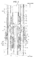
- a shock absorber 1 in Embodiment 1 will be described with reference to Figs. 1 to 4 .
- the description of this specification will be given based on the condition that sides illustrated by arrows in Fig. 1 and the like represent a first end side and a second end side, respectively.
- the shock absorber 1 includes a first end fixation portion 2; a second end fixation portion 3; an outer tube 11; an inner tube 12; a cylinder 21; a rod 22; a piston 23; a rod guide 36; multiple gas spring chambers; and lip packings for maintaining air-tight sealing between the gas spring chambers that are adjacent to each other.
- the shock absorber 1 is configured such that a first end of the inner tube 12 with a circular cylindrical shape is fixed to the first end fixation portion 2 in such a way that a first end opening of the inner tube 12 is sealed, a second end of the outer tube 11 with a circular cylindrical shape is fixed to the second end fixation portion 3 in such a way that a second end opening of the outer tube 11 is sealed, a second end of the inner tube 12 is inserted into the outer tube 11 via a first end opening of the outer tube 11, and the inner tube 12 and the outer tube 11 can move relative to each other along a center axis 13 of the inner tube 12 and the outer tube 11 in a state where air-tight sealing between an outer circumferential surface of the inner tube 12 and an inner circumferential surface of the outer tube 11 is formed.
- the first end fixation portion 2 and the second end fixation portion 3 move in such a way as to approach each other, and in an extension stroke, the first end fixation portion 2 and the second end fixation portion 3 move in such a way as to move away from each other.
- the shock absorber 1 includes the cylinder 21 and the rod 22 inside of the outer tube 11 and the inner tube 12.
- the cylinder 21 is formed in a circular cylindrical shape with a diameter smaller than an inner diameter of the inner tube 12
- the rod 22 is formed in a circular cylindrical shape with a diameter smaller than an inner diameter of the cylinder 21.
- a first end of the rod 22 is fixed to the first end fixation portion 2 in such a way that a first end opening of the rod 22 is sealed, a second end of the cylinder 21 is fixed to the second end fixation portion 3 in such a way that a second end opening of the cylinder 21 is sealed, a second end of the rod 22 is inserted into the cylinder 21 via a rod through hole 36h of the rod guide 36 provided at a first end opening of the cylinder 21, and the piston 23 is provided at the second end of the rod 22 which is inserted into the cylinder 21.
- the cylinder 21 is configured such that a second end of a first end cylinder 21 L is connected to a first end of a second end cylinder 21 U, a second end of the second end cylinder 21 U is fixed to the second end fixation portion 3, and the rod guide 36 is provided at a first end opening of the first end cylinder 21 L.
- the outer tube 11, the inner tube 12, the cylinder 21, the rod 22, and the piston 23 are provided coaxially with a center axis 13.
- the piston 23 and the rod guide 36 can move along the center axis 13 in such a way as to approach each other, or as to move away from each other in a state where air-tight sealing between an outer circumferential surface 23f of the piston 23, provided at the second end of the rod 22, and an inner circumferential surface 21 u of the cylinder 21 is maintained, and air-tight sealing between an outer circumferential surface RF of the rod 22 and the inner circumferential surface of the rod through hole 36h of the rod guide 36 is maintained.
- An interior of the shock absorber 1 is divided into an inner chamber 50 as a first gas spring chamber; an outer chamber 60 as a second gas spring chamber; and a balance chamber 70 as a third gas spring chamber.
- the shock absorber 1 includes a lip packing for maintaining air-tight sealing between the balance chamber 70 and the inner chamber 50 that are adjacent to each other, and a lip packing for maintaining air-tight sealing between the balance chamber 70 and the outer chamber 60 that are adjacent to each other.
- the inner chamber 50 is formed as a sealed space which is surrounded by the second end fixation portion 3, the piston 23, an inner circumferential surface of the cylinder 21 between the second end fixation portion 3 and the piston 23, and an outer circumferential surface of a sub-tank 38X.
- the outer chamber 60 is formed as a sealed space which is surrounded by the outer circumferential surface RF of the rod 22, the first end fixation portion 2, the inner circumferential surfaces of the inner tube 12 and the outer tube 11, the second end fixation portion 3, an outer circumferential surface of the cylinder 21, and a first end of the rod guide 36.
- the balance chamber 70 is formed as a sealed space which is surrounded by the piston 23, the rod guide 36, and the inner circumferential surface of the cylinder 21 between the piston 23 and the rod guide 36.
- a gas chamber 22U inside of the rod 22 communicates with the balance chamber 70 via a communication path 23B formed in the piston 23 such that the circular cylindrical rod 22 works as a sub-tank 22X that forms the gas chamber 22U for adjusting a compression ratio inside the balance chamber 70.
- the sub-tank 38X is provided at a second end of the piston 23 inside of the cylinder 21, and forms a gas chamber 38U for adjusting the internal compression ratio of the balance chamber 70 such that the gas chamber 38U communicates with the balance chamber 70 and the gas chamber 22U of the rod 22 via the communication path 23B formed in the piston 23.
- a rebound spring 40 is provided between a first end of the piston 23 and a second end of the rod guide 36 inside of the balance chamber 70 in such a way that the rebound spring 40 extends in a spiral manner along the center axis 13 of the rod 22 outside of the outer circumferential surface RF of the rod 22.
- a rod lip packing 72B is provided at the closest position to a first end of the balance chamber 70
- a piston lip packing 71 B is provided at the closest position to a second end of the balance chamber 70
- the rod lip packing 72B and the piston lip packing 71 B are disposed in such a way that the lips of the rod lip packing 72B and the piston lip packing 71 B face each other. Consequently, the rod lip packing 72B and the piston lip packing 71 B work as the rod lip packing 72B for the balance chamber 70 and the piston lip packing 71 B for the balance chamber 70 so that gas and sliding oil in the balance chamber 70 can be prevented from leaking to the outer chamber 60 and the inner chamber 50 when being compressed during extension operation of the shock absorber 1.
- a contact surface pressure PA between the minimum-diameter inner circumferential edge 76 of the rod lip packing 72B for the balance chamber 70 and the outer circumferential surface RF of the rod 22 is smaller than a contact surface pressure PM (refer to Fig. 9 ) therebetween when a minimum-diameter inner circumferential edge PE is formed in an edge shape (refer to Fig. 8 ).
- an arc-shaped surface of a minimum-diameter inner circumferential edge 76 protrudes toward the center axis 13.
- an arc-shaped surface of the maximum-diameter outer circumferential edge 78 protrudes in a direction away from the center axis 13.
- the arc-shaped surface of the minimum-diameter inner circumferential edge 76 and the arc-shaped surface of the maximum-diameter outer circumferential edge 78 are formed with a radial dimension (R dimension) of greater than 0.1 mm and less than 0.4 mm.
- R dimension radial dimension
- the radial dimension of the arc-shaped surfaces is in a range from 0.2 mm to 0.3 mm.
- the arc-shaped surfaces have a radial dimension less than or equal to 0.1 mm, a difference between a start-up torque value and a dynamic frictional value during the compression operation and the extension operation of the shock absorber 1 is increased, and a load is increased when switching between the compression operation and the extension operation occurs. Therefore, oil film shortage between the minimum-diameter inner circumferential edge 76 and the outer circumferential surface RF of the rod 22, and between the maximum-diameter outer circumferential edge 78 and the inner circumferential surface 21 u of the cylinder 21 may occur, and dynamic friction is likely to be increased, which is not desirable.
- arc-shaped surfaces have a radial dimension greater than or equal to 0.4 mm, performance of sealing between the minimum-diameter inner circumferential edge 76 and the outer circumferential surface RF of the rod 22, and between the maximum-diameter outer circumferential edge 78 and the inner circumferential surface 21u of the cylinder 21 may deteriorate, which is not desirable.
- the slide lubricating oil in the balance chamber 70 moves from the balance chamber 70 to the outer chamber 60, or from the balance chamber 70 to the inner chamber 50, since an amount of the slide lubricating oil sealed in the balance chamber 70 is small, the leaking slide lubricating oil may be unlikely to considerably affect pre-set reaction force characteristics of each of the gas spring chambers in the shock absorber 1, and the reaction force characteristics of each of the gas spring chambers are stable.
- a lip packing having the edge shape (refer to Fig. 8 ) at the maximum-diameter outer circumferential edge 78 which is in contact with the circumferential surface of the packing mounting groove is used as the rod lip packing 72B for the balance chamber 70, when the fluid pressure is applied to a region between the outer circumferential lip 77 and the inner circumferential lip 75, a contact surface pressure between a circumferential surface 72Br (refer to Fig. 2 ) of the packing mounting groove and the maximum-diameter outer circumferential edge 78 is maximized.
- gas and oil which have a tendency of passing through the gap between the circumferential surface 72Br of the packing mounting groove and the maximum-diameter outer circumferential edge 78, are prevented from moving from the balance chamber 70 to the outer chamber 60, and the reaction force characteristics of each of the gas spring chambers become more stable.
- a lip packing having the edge shape at the minimum-diameter inner circumferential edge 76 which is in contact with a circumferential surface 71 Br (refer to Fig. 2 ) of the packing mounting groove is used as the piston lip packing 71 B for the balance chamber 70, when the fluid pressure is applied to the region between the outer circumferential lip 77 and the inner circumferential lip 75, a contact surface pressure between the circumferential surface 71 Br of the packing mounting groove and the minimum-diameter inner circumferential edge 76 is maximized.
- the gas and the oil which have a tendency of passing through a gap between the circumferential surface 71Br of the packing mounting groove and the minimum-diameter inner circumferential edge 76, are prevented from moving from the balance chamber 70 to the inner chamber 50, and the reaction force characteristics of each of the gas spring chambers become more stable.
- rod lip packings 72A and 72C for the outer chamber 60 which are rod lip packings for the outer chamber 60 other than the rod lip packing for the balance chamber 70, and are mounted in such a way that the lips of the rod lip packings 72A and 72C for the outer chamber 60 face the first end fixation portion 2, lip packings having the edge shapes at a section of the minimum-diameter inner circumferential edge 76 of the inner circumferential lip 75 in contact with the outer circumferential surface RF of the rod 22 and at a section of the maximum-diameter outer circumferential edge 78 of the outer circumferential lip 77 in contact with each of circumferential surfaces 72Ar and 72Cr of the packing mounting grooves are used.
- lip packings with the configuration illustrated in Fig. 8 are used as the rod lip packings 72A and 72C for the outer chamber 60.
- a piston lip packing 71A for the inner chamber 50 which is a piston lip packing for the inner chamber 50 other than the piston lip packing for the balance chamber 70, and is mounted in such a way that the lip of the piston lip packing 71 A for the inner chamber 50 faces the second end fixation portion 3
- a lip packing having the edge shapes at a maximum-diameter outer circumferential edge 78 of the outer circumferential lip 77 in contact with the inner circumferential surface 21u of the cylinder 21 and at a section of the minimum-diameter inner circumferential edge 76 of the inner circumferential lip 75 in contact with a circumferential surface 71Ar of the packing mounting groove is used.
- a lip packing with the configuration illustrated in Fig. 8 is used as the piston lip packing 71A for the inner chamber 50.
- a contact surface pressure between the maximum-diameter outer circumferential edge 78 of the piston lip packing 71A for the inner chamber 50 and the inner circumferential surface 21u of the cylinder 21 is maximized, and a contact surface pressure between the minimum-diameter inner circumferential edge 76 and the circumferential surface 71Ar of the packing mounting groove is maximized.
- the gas and the oil are prevented from moving from the outer chamber 60 to the balance chamber 70, and from the inner chamber 50 to the balance chamber 70, and the pre-set reaction force characteristics of each of the gas spring chambers in the shock absorber 1 become stable.
- the gas spring shock absorber 1 it is possible to reduce the friction during the compression operation and the extension operation, it is possible to prevent the compression ratio adjustment oil from moving from the inner chamber 50 to the balance chamber 70, and from the outer chamber 60 to the balance chamber 70, and it is possible to stabilize the pre-set reaction force characteristics of each of the gas spring chambers. That is, it is possible to provide the gas spring shock absorber 1 in which both reducing the friction during the compression operation and the extension operation and stabilizing the reaction force characteristics of each of the gas spring chambers are achieved.
- the shock absorber 1 in Embodiment 1 is used as at least one front fork leg of a right front fork leg and a left front fork leg which constitute a front fork of a motorcycle or the like.
- a front fork which has the right front fork leg and the left front fork leg, and functions of which is divided between the right front fork leg and the left front fork leg, one of these two front fork legs is a damper leg with a damper, and the other of these two front fork legs is a spring leg with a spring
- the shock absorber 1 may be used as a spring leg having a gas spring in replacement of a metal spring.
- the shock absorber 1 is configured as an inverted front fork leg in which the rod 22 is positioned on a lower side and the cylinder 21 is positioned on an upper side.
- the front fork leg undergoes the compression operation in which a lower end (first ends of the inner tube 12 and the rod 22) of the front fork leg and an upper end (second ends of the outer tube 11 and the cylinder 21) of the front fork leg approach each other, and the extension operation in which the lower end of the front fork leg and the upper end of the front fork leg move away from each other.
- the piston 23 and the rod guide 36 move in such a way as to approach each other, and thus the volume of the rebound gas spring chamber 70 is reduced, and gas in the balance chamber 70 is compressed.
- gas sealed in the balance chamber 70, and the sub-tank 22X formed by the rod 22 and the sub-tank 38X inside of the cylinder 21 work as a gas spring in communication with the balance chamber 70, and generates a reaction force such that the front fork leg is caused to be compressed.
- a seal member 13C and a dust seal 13D are provided on the inner circumferential surface at the first end opening of the outer tube 11.
- Multiple bushes 13Z and 13B are provided on the inner circumferential surface of the outer tube 11. Consequently, the outer circumferential surface of the inner tube 12 can slide on the inner circumferential surface of the outer tube 11 while air-tight sealing therebetween is maintained via the bushes 13Z and 13B, the seal member 13C, and the dust seal 13D.
- a stopper ring 13E is fitted on an outer circumferential surface of the outer tube 11 at a portion close to the first end opening of the outer tube 11, such that a dust cover (not illustrated) for protecting the inner tube 12 does not damage the outer tube 11 due to slide contact between the dust cover and the outer tube 11.
- the rod guide 36 is configured as a combination of a cover 36A, a first end side packing mounting piece 36B, a second end side packing mounting piece 36C, and a spring seat and packing gland 36D.
- the cover 36A, the first end side packing mounting piece 36B, the second end side packing mounting piece 36C, and the spring seat and packing gland 36D are annular members, at the centers of which the respective rod through holes 36h, 36i, 36j, and 36k are formed to allow the rod 22 to pass therethrough.
- the outer circumferential surface of the cover 36A is provided with a screw portion 36b fitted to a screw portion 36a that is formed in the inner circumferential surface at the first end opening of the cylinder 21.
- the screw portions 36a and 36b are tightened together, and thus the cover 36A is fixed to the inside of the first end opening of the cylinder 21 using screw fitting.
- a bush 37 is provided on an inner circumferential surface of the rod through hole 36h of the cover 36A, and the outer circumferential surface RF of the rod 22 can slide on an inner circumferential surface of the bush 37.
- the first end side packing mounting piece 36B is attached to a second end of the cover 36A.
- An O-ring 73B is mounted in an O-ring mounting groove formed at the outer circumferential surface of the first end side packing mounting piece 36B.
- Packing mounting grooves centered on the rod through hole 36i are respectively formed at a first end surface and a second end surface of the first end side packing mounting piece 36B.
- the rod lip packing 72A for the outer chamber 60 is mounted in the packing mounting groove formed in a first end surface of the first end side packing mounting piece 36B.
- the rod lip packing 72C for the outer chamber 60 is mounted in the packing mounting groove formed in the second end surface of the first end side packing mounting piece 36B.
- the second end side packing mounting piece 36C is mounted on the second end surface of the first end side packing mounting piece 36B.
- An O-ring 73C is mounted in an O-ring mounting groove formed at the outer circumferential surface of the second end side packing mounting piece 36C.
- a packing mounting groove centered on the rod through hole 36j is formed at a second end surface of the second end side packing mounting piece 36C, and the rod lip packing 72B for the balance chamber 70 is mounted in this packing mounting groove.
- the second end of the rod 22 passes through the rod through hole 36h of the rod guide 36, is inserted into the cylinder 21, and passes through a spiral central hole of the rebound spring 40 inserted into the cylinder 21, and then the piston 23 is attached to the second end of the rod 22. That is, an insertion hole 23c, into which a second end portion of the rod 22 is inserted, is formed at a center of the first end of the columnar piston 23, and an outer circumferential surface of the second end portion of the rod 22 is provided with a screw portion 23b screw-fitted to a screw portion 23a that is formed in the inner circumferential surface of the insertion hole 23c.
- a spring colliding surface 23d is formed at a second end of the outer circumferential surface of the portion where the insertion hole 23c is formed in the piston 23, and is a surface a diameter of which is greater than that of the outer circumferential surface of the portion where the insertion hole 23c is formed in the piston 23.
- a second end of the rebound spring 40 collides with the spring colliding surface 23d, and thus the rebound spring 40 is prevented from extending past a predetermined distance.
- circular annular packing mounting grooves centered on the center axis 13 of the piston 23 are respectively provided at a first end and a second end of an outer circumferential surface facing the inner circumferential surface of the cylinder 21.
- a circular annular piston ring mounting groove centered on the center axis 13 of the piston is formed at the first end of the outer circumferential surface of the piston 23. Slidability of the piston 23 is improved due to contact between a piston ring 24 mounted in the piston ring mounting groove and the inner circumferential surface 21 u of the cylinder 21.
- the piston lip packing 71A for the inner chamber 50 is mounted in the packing mounting groove at the second end of the outer circumferential surface of the piston 23, and the piston lip packing 71 B for the balance chamber 70 is mounted in the packing mounting groove at the first end of the outer circumferential surface of the piston 23.
- the second end of the piston 23 includes a sub-tank connection portion.
- the sub-tank connection portion is formed in a cylindrical shape, and a diameter of an outer circumferential surface of the sub-tank connection portion is smaller than that of the outer circumferential surface of the piston 23.
- the sub-tank 38X is formed as a hollow bar-like container with an open first end and a blocked second end.
- a second end of the outer circumferential surface of the sub-tank connection portion is provided with a screw portion 25b fitted to a screw portion 25a that is formed on the inner circumferential surface of the sub-tank 38X at a portion close to the first end opening of the sub-tank 38X.
- the communication path 23B is formed in the piston 23, and the gas chamber 38U inside of the sub-tank 38X, and the gas chamber 22U formed inside of the rod 22 communicate with the balance chamber 70 via the communication path 23B. That is, since the shock absorber 1 includes the sub-tank 22X formed by the rod 22 that partitions off the gas chamber 22U formed inside the rod 22 while communicating with the balance chamber 70, it is possible to increase a volume of the balance chamber 70, and to decrease a compression ratio even in high-pressure conditions. Accordingly, it is possible to stabilize the reaction force characteristics in a vicinity of an extension limit of the extension operation, and to improve operation stability.
- the sub-tank 38X is provided inside of the cylinder 21, while forming the gas chamber 38U for adjusting the internal compression ratio of the balance chamber 70, and communicating with the balance chamber 70 via the communication path 23B formed in the piston 23, it is possible to increase the volume of the balance chamber 70, and to decrease a compression ratio even in high-pressure conditions. Therefore, it is possible to stabilize the reaction force characteristics in the vicinity of the extension limit of the extension operation, and to improve the operation stability. Since the shock absorber 1 includes the sub-tanks 22X and 38X, it is possible to further stabilize the reaction force characteristics in the vicinity of the extension limit of the extension operation.
- An oscillation preventive collar 21 Z is attached to a first end of an outer circumferential portion of the cylinder 21 with an annular gap formed between the oscillation preventive collar 21Z and an inner circumferential surface of the inner tube 12.
- the first end fixation portion 2 connected to the axle of the motorcycle, includes a bracket 32; a bottom piece 33; and a bottom bolt 34.
- the bottom piece 33 is attached to the first end opening of the inner tube 12 in such a way that the first end opening of the inner tube 12 is sealed.
- the bracket 32 includes a fitting portion 32A that is fitted to the first end of the inner tube 12 to which the bottom piece 33 is attached; a connection hole 32B for connecting the axle; and a bottom bolt attaching hole 32C in which the bottom bolt 34 is attached.
- a first end portion of the rod 22 passes through a central hole of the bottom piece 33 inserted into the fitting portion 32A, protrudes into the bottom bolt attaching hole 32C, is screwed into the bottom bolt 34 attached to the bottom bolt attaching hole 32C, and is fixed with a lock nut 35.
- seal members 63A, 63B, 74, and the like such as O-rings.
- a gas pressure adjustment unit 65 is provided in the bottom bolt 34 in such a way as to communicate with the inside of the rod 22 via the first end opening of the rod 22.
- the gas pressure adjustment unit 65 it is possible to prevent gas from flowing to the outside from an internal space of the rod 22, and it is possible to adjust the gas pressure of the balance chamber 70 by adjusting the compression ratio of gas in the balance chamber 70 via the gas chamber 22U inside of the rod 22.
- the second end fixation portion 3 is configured to include a second end portion of the outer tube 11, and a cap 30 and a bolt portion 31 which air-tightly block the second end openings of the outer tube 11 and the cylinder 21.
- the second end portion of the outer tube 11, in which the second end openings of the outer tube 11 and the cylinder 21 are blocked with the cap 30 and the bolt portion 31, is connected to the frame or the like which configures the body of the motorcycle.
- air-tight sealing between the inside of the outer tube 11 and the outside, and between the inside of the cylinder 21 and the outside is maintained due to seal members 52, 61A, 61 B, and the like such as O-rings.
- the bolt portion 31 includes an inner chamber gas pressure adjustment unit 53A for adjusting a pressure of gas sealed in the inner chamber 50, and an outer chamber gas pressure adjustment unit 53B for adjusting a pressure of gas sealed in the outer chamber 60.
- the first end fixation portion 2 is provided with a sub-tank (not illustrated) that communicates with the gas chamber 22U inside of the rod 22 via the first end opening of the rod 22, it is possible to further increase the volume of the balance chamber 70, and to decrease a compression ratio even in high-pressure conditions. That is, if a sub-tank (not illustrated) is provided and forms a gas chamber for adjusting the compression ratio in the balance chamber 70 such that the gas chamber communicates with the gas chamber 22U inside of the rod 22 and the balance chamber 70 via the first end opening of the rod 22 fixed to the first end fixation portion 2, it is possible to further increase the volume of the balance chamber 70, and to decrease the compression ratio even in high-pressure conditions.
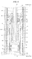
- a shock absorber 1A in Embodiment 2 will be described with reference to Figs. 5 and 6 and also Figs. 3 and 4 .
- the shock absorber 1A is configured such that a first end of an inner tube 12A with a circular cylindrical shape is fixed to a first end fixation portion 2A in such a way that a first end opening of the inner tube 12A is sealed, a second end of an outer tube 11A with a circular cylindrical shape is fixed to a second end fixation portion 3A in such a way that a second end opening of the outer tube 11 A is sealed, a second end of the inner tube 12A is inserted into the outer tube 11A via a first end opening of the outer tube 11A, and the inner tube 12A and the outer tube 11A can move relative to each other along a center axis 13A of the inner tube 12A and the outer tube 11A in a state where air-tight sealing between an outer circumferential surface of the inner tube 12A and an inner circumferential surface of the outer tube 11A is formed. Therefore, the first end fixation portion 2A and the second end fixation portion 3A move in such a way as to approach each other, or as to move away from each
- the shock absorber 1A includes a cylinder 21A and a rod 22A inside of the outer tube 11A and the inner tube 12A.
- the cylinder 21A is formed in a cylindrical shape with a diameter smaller than an inner diameter of the inner tube 12A
- the rod 22A is formed in a cylindrical shape with a diameter smaller than an inner diameter of the cylinder 21A.
- a first end of the cylinder 21A is fixed to the first end fixation portion 2A in such a way that a first end opening of the cylinder 21A is sealed, a second end of the rod 22A is fixed to the second end fixation portion 3A in such a way that a second end opening of the rod 22A is sealed, a first end of the rod 22A is inserted into the cylinder 21A via a rod through hole 360h of a rod guide 360 provided at a second end opening of the cylinder 21A, and a piston 230 is provided on a first end portion of the rod 22A which is inserted into the cylinder 21A.
- the outer tube 11A, the inner tube 12A, the cylinder 21A, the rod 22A, the piston 230, and the rod guide 360 are provided coaxially with a center axis 13A.
- the piston 230 and the rod guide 360 move along the center axis 13A in such a way as to move away from each other, or as to approach each other in a state where air-tight sealing between an outer circumferential surface 230f of the piston 230, provided on the first end portion of the rod 22A, and an inner circumferential surface 210u of the cylinder 21A is maintained, and air-tight sealing between an outer circumferential surface RF of the rod 22A and an inner circumferential surface of the rod through hole 360h of the rod guide 360 is maintained.
- a rebound spring 40A is provided between a second end of the piston 230 and a first end of the rod guide 360 in such a way that the rebound spring 40A extends in a spiral manner along the center axis 13A of the rod 22A outside of the outer circumferential surface RF of the rod 22A.
- a gas chamber inside of the rod 22A communicates with a balance chamber 70A (which is a third gas spring chamber) via a communication path 230B formed in the piston 230 such that the circular cylindrical rod 22A works as a sub-tank that forms the gas chamber for adjusting a compression ratio inside the balance chamber 70A.
- a balance chamber 70A which is a third gas spring chamber
- the shock absorber 1A includes a lip packing for maintaining air-tight sealing between the balance chamber 70A and the inner chamber 50A that are adjacent to each other, and a lip packing for maintaining air-tight sealing between the balance chamber 70A and the outer chamber 60A that are adjacent to each other.
- the inner chamber 50A is formed as a space which is surrounded by the first end fixation portion 2A, the piston 230, and an inner circumferential surface of the cylinder 21 A between the first end fixation portion 2A and the piston 230.
- the outer chamber 60A is formed as a sealed space which is surrounded by the outer circumferential surface RF of the rod 22A, the second end fixation portion 3A, the inner circumferential surfaces of the inner tube 12A and the outer tube 11 A, and the rod guide 360.
- the balance chamber 70A is formed as a space which is surrounded by the piston 230, the rod guide 360, and an inner circumferential surface 210u of the cylinder 21A between the piston 230 and the rod guide 360.
- a rod lip packing 720B is provided at the closest position to a second end of the balance chamber 70A
- a piston lip packing 710B is provided at the closest position to a first end of the balance chamber 70A
- the rod lip packing 720B and the piston lip packing 710B are disposed in such a way that the lips of the rod lip packing 720B and the piston lip packing 710B face each other.
- the rod lip packing 720B and the piston lip packing 710B work as the rod lip packing 720B for the balance chamber 70A and the piston lip packing 710B for the balance chamber 70A so that gas and sliding oil in the balance chamber 70A can be prevented from leaking to the outer chamber 60A and the inner chamber 50A when being compressed during extension operation of the shock absorber 1A.
- a contact surface pressure PA between the minimum-diameter inner circumferential edge 76 of the rod lip packing 720B for the balance chamber 70A and the outer circumferential surface RF of the rod 22A is smaller than a contact surface pressure PM (refer to Fig. 9 ) therebetween when a minimum-diameter inner circumferential edge PE is formed in an edge shape (refer to Fig. 8 ).
- an arc-shaped surface of a minimum-diameter inner circumferential edge 76 protrudes toward the center axis 13A.
- an arc-shaped surface of the maximum-diameter outer circumferential edge 78 protrudes in a direction away from the center axis 13A.
- the arc-shaped surface of the minimum-diameter inner circumferential edge 76 and the arc-shaped surface of the maximum-diameter outer circumferential edge 78 is formed with a radial dimension (R dimension) of greater than 0.1 mm and less than 0.4 mm.
- R dimension a radial dimension of the arc-shaped surfaces.
- the radial dimension of the arc-shaped surfaces is in a range from 0.2 mm to 0.3 mm.
- the arc-shaped surfaces have a radial dimension less than or equal to 0.1 mm, a difference between a start-up torque value and a dynamic frictional value during the compression operation and the extension operation of the shock absorber 1A is increased, and a load is increased when switching between the compression operation and the extension operation occurs. Therefore, oil film shortage between the minimum-diameter inner circumferential edge 76 and the outer circumferential surface RF of the rod 22A, and between the maximum-diameter outer circumferential edge 78 and the inner circumferential surface 210u of the cylinder 21 A may occur, and dynamic friction is likely to be increased, which is not desirable.
- arc-shaped surfaces have a radial dimension greater than or equal to 0.4 mm, performance of sealing between the minimum-diameter inner circumferential edge 76 and the outer circumferential surface RF of the rod 22A, and between the maximum-diameter outer circumferential edge 78 and the inner circumferential surface 210u of the cylinder 21 A may deteriorate, which is not desirable.
- the slide lubricating oil in the balance chamber 70A moves from the balance chamber 70A to the outer chamber 60A, or from the balance chamber 70A to the inner chamber 50A, since an amount of the slide lubricating oil sealed in the balance chamber 70A is small, the leaking slide lubricating oil may be unlikely to considerably affect pre-set reaction force characteristics of each of the gas spring chambers in the shock absorber 1A, and the reaction force characteristics of each of the gas spring chambers are stable.
- a lip packing having the edge shape (refer to Fig. 8 ) at the maximum-diameter outer circumferential edge 78 which is in contact with the circumferential surface of the packing mounting groove is used as the rod lip packing 720B for the balance chamber 70A, when the fluid pressure is applied to a region between the outer circumferential lip 77 and the inner circumferential lip 75, the contact surface pressure between the circumferential surface of the packing mounting groove and the maximum-diameter outer circumferential edge 78 is maximized.
- gas and oil which have a tendency of passing through the gap between the circumferential surface of the packing mounting groove and the maximum-diameter outer circumferential edge 78, are prevented from moving from the balance chamber 70A to the outer chamber 60A, and the reaction force characteristics of each of the gas spring chambers become more stable.
- the gas and the oil which have a tendency of passing through a gap between the circumferential surface of the packing mounting groove and the minimum-diameter inner circumferential edge 76, are prevented from moving from the balance chamber 70A to the inner chamber 50A, and the reaction force characteristics of each of the gas spring chambers become more stable.
- a rod lip packing 720A for the outer chamber 60A which is a rod lip packing for the outer chamber other than the rod lip packing for the balance chamber 70A, and is mounted in such a way that the lips of the rod lip packing 720A for the outer chamber 60A faces the second end fixation portion 3A
- a lip packing having the edge shape at a section of the minimum-diameter inner circumferential edge 76 of the inner circumferential lip 75 in contact with the outer circumferential surface RF of the rod 22A, and at a section of the maximum-diameter outer circumferential edge 78 of the outer circumferential lip 77 in contact with the circumferential surface of the packing mounting groove is used.
- a lip packing with a configuration illustrated in Fig. 8 is used as the rod lip packing 720A for the outer chamber 60A.
- a piston lip packing 710A for the inner chamber 50A which is a piston lip packing for the inner chamber 50A other than the piston lip packing for the balance chamber 70A, and is mounted in such a way that the lip of the piston lip packing 710A for the inner chamber 50A faces the second end fixation portion 3A
- a lip packing having the edge shape at a section of the maximum-diameter outer circumferential edge 78 of the outer circumferential lip 77 in contact with the inner circumferential surface 210u of the cylinder 21A, and at a section of the minimum-diameter inner circumferential edge 76 of the inner circumferential lip 75 in contact with the circumferential surface of the packing mounting groove is used.
- a lip packing with the configuration illustrated in Fig. 8 is used as the piston lip packing 710A for the inner chamber 50A.
- a contact surface pressure between the maximum-diameter outer circumferential edge 78 of the piston lip packing 710A for the inner chamber 50A and the inner circumferential surface 210u of the cylinder 21A is maximized, and a contact surface pressure between the minimum-diameter inner circumferential edge 76 and the circumferential surface of the packing mounting groove is maximized. Accordingly, the gas and the oil are prevented from moving from the outer chamber 60A to the balance chamber 70A, and from the inner chamber 50A to the balance chamber 70A, and the pre-set reaction force characteristics of each of the gas spring chambers in the shock absorber 1A becomes stable.
- the gas spring shock absorber 1A according to Embodiment 2 it is possible to reduce the friction during the compression operation and the extension operation, it is possible to prevent the compression ratio adjustment oil from moving from the inner chamber 50A to the balance chamber 70A, and from the outer chamber 60A to the balance chamber 70A, and it is possible to stabilize the pre-set reaction force characteristics of each of the gas spring chambers. That is, it is possible to provide the gas spring shock absorber 1A in which both reducing the friction during the compression operation and the extension operation and stabilizing the reaction force characteristics of each of the gas spring chambers are achieved.
- the shock absorber 1A in Embodiment 2 is used as at least one front fork leg of a right front fork leg and a left front fork leg which constitute a front fork of a motorcycle or the like.
- a front fork which has the right front fork leg and the left front fork leg, and functions of which is divided between the right front fork leg and the left front fork leg, one of these two front fork legs is a damper leg with a damper, and the other of these two front fork legs is a spring leg with a spring
- the shock absorber 1A may be used as a spring leg having a gas spring in replacement of a metal spring.
- the shock absorber 1A is configured as an upright cartridge (damper) front fork leg in which the rod 22A is positioned on an upper side and the cylinder 21A is positioned on a lower side.
- a seal member 130C is provided on the inner circumferential surface at the first end opening of the outer tube 11 A.
- Multiple bushes 130A and 130B are provided on the inner circumferential surface of the outer tube 11 A. Consequently, the outer circumferential surface of the inner tube 12A can slide on the inner circumferential surface of the outer tube 11Awhile air-tight sealing therebetween is maintained via the bushes 130A and 130B, and the seal member 130C.
- a bush 370 is provided on an inner circumferential surface of the rod guide 360, and packing mounting grooves centered on the rod through hole 360h are respectively formed at a first end inner surface and a second end inner surface of the rod guide 360.
- the rod lip packing 720B for the balance chamber 70A is mounted in the packing mounting groove formed in the first end surface, and the rod lip packing 720A for the outer chamber 60A is mounted in the packing mounting groove formed in the second end surface.
- An O-ring 312 is mounted in an O-ring mounting groove formed in an outer circumferential surface of the rod guide 360.
- the rod guide 360 and the inner tube 12A can move relative to each other in a state where air-tight sealing between the O-ring 312 and the inner circumferential surface of the inner tube 12A is formed. Since the O-ring 312 is in air-tight contact with the inner circumferential surface of the inner tube 12A, a sub-tank is formed by a gas chamber 700 that is formed between the outer circumferential surface of the cylinder 21A and the inner circumferential surface of the inner tube 12A, and communicates with the balance chamber 70A via a communication hole 362.
- the rod guide 360 is provided at a second end of the cylinder 21A in such a way that a first end of a first end connection portion 361 of the rod guide 360 is connected to the second end opening of the cylinder 21A using screw fitting, and thus the cylinder 21A and the rod guide 360 move together. It is possible to change a volume of the gas chamber 700 by changing a length of the cylinder 21A.
- the communication hole 362 is formed in the first end connection portion 361.
- the first end of the rod 22A passes through the rod through hole 360h of the rod guide 360, is inserted into the cylinder 21A, and passes through a spiral central hole of the rebound spring 40A, and then the piston 230 is attached to the first end of the rod 22A.
- the first end of the rod 22A is inserted into a cylindrical rod insertion hole portion 230a which is formed in a connection portion and spring fixation portion 230A provided at the second end of the piston 230, and the rod insertion hole portion 230a is connected to the first end of the rod 22A using screw fitting.
- An outer diameter of an outer circumferential surface of the rod insertion hole portion 230a is smaller than an inner diameter of the spiral central hole of the rebound spring 40A.
- the outer circumferential surface of the rod insertion hole portion 230a enters the spiral central hole via a first end opening of the spiral central hole.
- a first end of the rebound spring 40A is fixed to a spring fixation portion formed on the outer circumferential surface of the rod insertion hole portion 230a, a spring colliding surface is formed in a first end surface of the rod guide 360, and a second end of the rebound spring 40A collides with the spring colliding surface, and thus the rebound spring 40A prevents the shock absorber 1A from extending beyond a certain point.
- Circular annular packing mounting grooves centered on the central axis 13A of the piston 230 are respectively provided at a first end and a second end of an outer circumferential surface of a circular columnar piston main body provided at a first end of the piston 230, and a circular annular piston ring mounting groove centered on the central axis 13A of the piston 230 is formed at a second end of the outer circumferential surface of the piston main body.
- piston lip packing 710A for the inner chamber 50A is mounted in the packing mounting groove at the first end of the outer circumferential surface of the piston 230
- piston lip packing 710B for the balance chamber 70A is mounted in the packing mounting groove at the second end of the outer circumferential surface of the piston 230.
- the shock absorber 1 A includes the sub-tank formed by the rod 22A that forms the gas chamber thereinside which communicates with the balance chamber 70A via the communication path 230B, and the sub-tank that forms the gas chamber 700 which communicates with the balance chamber 70A via the communication hole 362 formed in the first end connection portion 361 of the rod guide 360, it is possible to increase a volume of the balance chamber 70A, and to decrease the compression ratio even in high-pressure conditions. Accordingly, it is possible to stabilize the reaction force characteristics in a vicinity of an extension limit of the extension operation, and thus to improve operation stability.
- gas chamber 700 is a sub-tank that is partitioned off by the first end fixation portion 2A, the rod guide 360, and the outer circumferential surface of the cylinder 21A and the inner circumferential surface of the inner tube 12A between the first end fixation portion 2A and the rod guide 360.
- the first end fixation portion 2A includes a first end fitting portion 41; an axle connection hole 42 to which the axle of the motorcycle is connected; a gas pressure adjustment unit 43; a quick coupler 44A; and a quick coupler 44B.
- the first end fitting portion 41 is formed in a circular cylindrical shape with an outer diameter smaller than an inner diameter of a first end opening portion of the inner tube 12A, and with an inner diameter greater than an outer diameter of a first end opening portion of the cylinder 21 A.
- the first end fitting portion 41 is fitted into the inner tube 12A via the first end opening of the inner tube 12A, and the first end opening portion of the cylinder 21A is inserted and fitted into the first end fitting portion 41.
- the first end fitting portion 41 is liquid-tightly screwed with the inner tube 12A with a seal member 314F interposed therebetween.
- a bottom piece 314 is disposed at the first end of the cylinder 21 A, and the cylinder 21A is liquid-tightly fitted into the first end fitting portion 41 with the bottom piece 314 and seal members 314S and 314G (which are provided on the outer circumference of the bottom piece 314) interposed therebetween.
- the gas pressure adjustment unit 43 communicates with the inner chamber 50A via a sub-tank 43S. Accordingly, by virtue of the gas pressure adjustment unit 43, it is possible to prevent gas from flowing to the outside from the internal space of the inner chamber 50A, and it is possible to adjust a pressure of gas sealed in the inner chamber 50A during adjustment.
- the quick coupler 44A is an oil filler port through which the inner chamber 50A is filled with compression ratio adjustment oil
- the quick coupler 44B is an oil filler port through which the balance chamber 70A is filled with a small amount of oil for forming a sliding oil film. Accordingly, it is possible to adjust the volume of the inner chamber 50A, it is easy to adjust the compression ratio, and it is possible to adjust the amount of slide oil inside of the balance chamber 70A.
- the inner chamber 50A communicates with the gas pressure adjustment unit 43 via a tube 43T.
- the tube 43T is supported by a tube supporting portion 43A, and it is possible to fill the inner chamber 50A with the gas via the tube 43T using the gas pressure adjustment unit 43.
- An end portion of the tube 43T is disposed to protrude further toward the vehicle body than a liquid surface of oil O inside of the inner chamber 50A. For this reason, it is possible to prevent the oil from being discharged via the gas pressure adjustment unit 43 even if the gas pressure inside the inner chamber 50A is adjusted (reduced).
- the second end fixation portion 3A includes a second end portion of the outer tube 11 A, and a bolt portion 30A and a cap 31 A which air-tightly block the second end openings of the outer tube 11A and the rod 22A.
- the bolt portion 30A is connected to the second end opening of the outer tube 11A using screw fitting, and the bolt portion 30A is connected to the second end opening of the rod 21A using screw fitting.
- the cap 31A includes a gas pressure adjustment unit 214Afor adjusting a pressure of gas sealed in the gas chamber inside of the rod 22A, and an outer chamber gas pressure adjustment unit 214B for adjusting a pressure of gas sealed in the outer chamber 60A.
- the second end portion of the outer tube 11A which is blocked with the cap 31A and the bolt portion 30A, is connected to the frame or the like which configures the body of the motorcycle.
- the frame or the like which configures the body of the motorcycle.
- air-tight sealing between the inside of the outer tube 11A and the outside, and between the inside of the cylinder 21A and the outside is maintained due to seal members 52, 61A, 61 B, 216, and the like such as O-rings.
- a rubber bumper 325 is fixed to a central portion of the outer circumferential surface RF of the rod 22A.
- the rubber bumper 325 reduces an impact when the inner tube 12A hits the bolt portion 30A during the compression operation of the shock absorber 1A by that the second end of the inner tube 12A comes into metal-to-metal contact with the bolt portion 30A after the rubber bumper 325 is bent by approximately 4 mm.
- the upright cartridge (damper) shock absorber 1A described in Embodiment 2 may be configured not to include the sub-tank 43S and the sub-tank which forms the gas chamber 700.
Landscapes
- Engineering & Computer Science (AREA)
- General Engineering & Computer Science (AREA)
- Mechanical Engineering (AREA)
- Fluid-Damping Devices (AREA)
- Axle Suspensions And Sidecars For Cycles (AREA)
- Sealing With Elastic Sealing Lips (AREA)
Applications Claiming Priority (1)
| Application Number | Priority Date | Filing Date | Title |
|---|---|---|---|
| JP2015035180A JP6407059B2 (ja) | 2015-02-25 | 2015-02-25 | 緩衝器 |
Publications (3)
| Publication Number | Publication Date |
|---|---|
| EP3073145A2 true EP3073145A2 (fr) | 2016-09-28 |
| EP3073145A3 EP3073145A3 (fr) | 2016-11-16 |
| EP3073145B1 EP3073145B1 (fr) | 2018-04-18 |
Family
ID=55451034
Family Applications (1)
| Application Number | Title | Priority Date | Filing Date |
|---|---|---|---|
| EP16157281.3A Active EP3073145B1 (fr) | 2015-02-25 | 2016-02-25 | Amortisseur de chocs |
Country Status (3)
| Country | Link |
|---|---|
| US (1) | US9878759B2 (fr) |
| EP (1) | EP3073145B1 (fr) |
| JP (1) | JP6407059B2 (fr) |
Families Citing this family (4)
| Publication number | Priority date | Publication date | Assignee | Title |
|---|---|---|---|---|
| USD828790S1 (en) * | 2016-11-14 | 2018-09-18 | Showa Corporation | Shock absorber |
| CN108167263B (zh) * | 2017-12-08 | 2019-10-22 | 中国航天空气动力技术研究院 | 一种压缩量可调的动密封结构 |
| EP3822509B1 (fr) * | 2018-07-09 | 2024-11-13 | Hitachi Astemo, Ltd. | Amortisseur |
| US20240308619A1 (en) * | 2023-03-13 | 2024-09-19 | Push Industries Incorporated | Fork Chassis Air Bleeder |
Citations (1)
| Publication number | Priority date | Publication date | Assignee | Title |
|---|---|---|---|---|
| JP2013228089A (ja) | 2012-03-30 | 2013-11-07 | Showa Corp | フロントフォークのスプリング脚 |
Family Cites Families (7)
| Publication number | Priority date | Publication date | Assignee | Title |
|---|---|---|---|---|
| US2404111A (en) * | 1942-11-17 | 1946-07-16 | Dowty Equipment Ltd | Resilient telescopic unit |
| US3439499A (en) * | 1967-02-13 | 1969-04-22 | York Gears Ltd | Shock absorber |
| US4729529A (en) * | 1985-12-19 | 1988-03-08 | Pneumo Corporation | Landing gear mechanism including bypass valve assembly for reducing damping loads during taxiing |
| JPH1054435A (ja) * | 1996-08-09 | 1998-02-24 | Tokico Ltd | ガススプリング |
| FR2933676B1 (fr) * | 2008-07-11 | 2010-08-27 | Tetra Laval Holdings & Finance | Bouchon pour un col de recipient et machine de moulage d'une matiere plastique pour fabriquer un tel bouchon. |
| JP5240571B2 (ja) * | 2009-02-16 | 2013-07-17 | 本田技研工業株式会社 | フロントフォーク |
| JP2014114883A (ja) | 2012-12-10 | 2014-06-26 | Yamaha Motor Co Ltd | エアショックアブソーバ及び鞍乗り型車両 |
-
2015
- 2015-02-25 JP JP2015035180A patent/JP6407059B2/ja active Active
-
2016
- 2016-02-23 US US15/051,019 patent/US9878759B2/en active Active
- 2016-02-25 EP EP16157281.3A patent/EP3073145B1/fr active Active
Patent Citations (1)
| Publication number | Priority date | Publication date | Assignee | Title |
|---|---|---|---|---|
| JP2013228089A (ja) | 2012-03-30 | 2013-11-07 | Showa Corp | フロントフォークのスプリング脚 |
Also Published As
| Publication number | Publication date |
|---|---|
| US9878759B2 (en) | 2018-01-30 |
| JP6407059B2 (ja) | 2018-10-17 |
| EP3073145A3 (fr) | 2016-11-16 |
| JP2016156466A (ja) | 2016-09-01 |
| US20160244121A1 (en) | 2016-08-25 |
| EP3073145B1 (fr) | 2018-04-18 |
Similar Documents
| Publication | Publication Date | Title |
|---|---|---|
| EP3073145B1 (fr) | Amortisseur de chocs | |
| US6918605B2 (en) | Inverted type front fork in two-wheeled vehicle or the like | |
| CN102307738B (zh) | 具有缩短的中间管的三管减震器 | |
| US8794406B2 (en) | Stiff damper | |
| US10400843B2 (en) | Damper | |
| US20060054435A1 (en) | Hydraulic shock absorber | |
| US9156327B2 (en) | Suspension device | |
| US9541152B2 (en) | Suspension apparatus | |
| EP3072711A1 (fr) | Suspension d'air | |
| JP2015087008A (ja) | 懸架装置および懸架システム | |
| CN107429775B (zh) | 前叉 | |
| US20080053764A1 (en) | Front fork | |
| US20090107785A1 (en) | Hydraulic shock absorber | |
| WO2012073930A1 (fr) | Amortisseur de chocs | |
| US7240775B2 (en) | Shock absorber | |
| JP6363361B2 (ja) | 懸架装置 | |
| US11592074B2 (en) | Position-dependent shock absorber | |
| US8191693B2 (en) | Vibration damper | |
| CN114877073B (zh) | 密封结构、减振器和车辆 | |
| JP7438394B2 (ja) | 緩衝器 | |
| KR19990001448A (ko) | 유압완충기 | |
| WO2018029874A1 (fr) | Fourche avant | |
| JP2025082685A (ja) | 緩衝器 | |
| KR20250140615A (ko) | 완충 장치, 현가 장치 | |
| GB2544245A (en) | Hydraulic shock-absorbing device |
Legal Events
| Date | Code | Title | Description |
|---|---|---|---|
| PUAI | Public reference made under article 153(3) epc to a published international application that has entered the european phase |
Free format text: ORIGINAL CODE: 0009012 |
|
| AK | Designated contracting states |
Kind code of ref document: A2 Designated state(s): AL AT BE BG CH CY CZ DE DK EE ES FI FR GB GR HR HU IE IS IT LI LT LU LV MC MK MT NL NO PL PT RO RS SE SI SK SM TR |
|
| AX | Request for extension of the european patent |
Extension state: BA ME |
|
| PUAL | Search report despatched |
Free format text: ORIGINAL CODE: 0009013 |
|
| AK | Designated contracting states |
Kind code of ref document: A3 Designated state(s): AL AT BE BG CH CY CZ DE DK EE ES FI FR GB GR HR HU IE IS IT LI LT LU LV MC MK MT NL NO PL PT RO RS SE SI SK SM TR |
|
| AX | Request for extension of the european patent |
Extension state: BA ME |
|
| RIC1 | Information provided on ipc code assigned before grant |
Ipc: F16F 9/06 20060101ALI20161012BHEP Ipc: F16F 9/36 20060101AFI20161012BHEP Ipc: B62K 25/08 20060101ALI20161012BHEP Ipc: F16J 15/3204 20160101ALI20161012BHEP Ipc: F16F 9/18 20060101ALI20161012BHEP Ipc: F16J 15/3232 20160101ALI20161012BHEP |
|
| STAA | Information on the status of an ep patent application or granted ep patent |
Free format text: STATUS: REQUEST FOR EXAMINATION WAS MADE |
|
| 17P | Request for examination filed |
Effective date: 20170516 |
|
| RBV | Designated contracting states (corrected) |
Designated state(s): AL AT BE BG CH CY CZ DE DK EE ES FI FR GB GR HR HU IE IS IT LI LT LU LV MC MK MT NL NO PL PT RO RS SE SI SK SM TR |
|
| GRAP | Despatch of communication of intention to grant a patent |
Free format text: ORIGINAL CODE: EPIDOSNIGR1 |
|
| STAA | Information on the status of an ep patent application or granted ep patent |
Free format text: STATUS: GRANT OF PATENT IS INTENDED |
|
| INTG | Intention to grant announced |
Effective date: 20171031 |
|
| GRAS | Grant fee paid |
Free format text: ORIGINAL CODE: EPIDOSNIGR3 |
|
| GRAA | (expected) grant |
Free format text: ORIGINAL CODE: 0009210 |
|
| STAA | Information on the status of an ep patent application or granted ep patent |
Free format text: STATUS: THE PATENT HAS BEEN GRANTED |
|
| AK | Designated contracting states |
Kind code of ref document: B1 Designated state(s): AL AT BE BG CH CY CZ DE DK EE ES FI FR GB GR HR HU IE IS IT LI LT LU LV MC MK MT NL NO PL PT RO RS SE SI SK SM TR |
|
| REG | Reference to a national code |
Ref country code: GB Ref legal event code: FG4D |
|
| REG | Reference to a national code |
Ref country code: CH Ref legal event code: EP |
|
| REG | Reference to a national code |
Ref country code: AT Ref legal event code: REF Ref document number: 990840 Country of ref document: AT Kind code of ref document: T Effective date: 20180515 |
|
| REG | Reference to a national code |
Ref country code: IE Ref legal event code: FG4D |
|
| REG | Reference to a national code |
Ref country code: DE Ref legal event code: R096 Ref document number: 602016002450 Country of ref document: DE |
|
| REG | Reference to a national code |
Ref country code: SE Ref legal event code: TRGR |
|
| REG | Reference to a national code |
Ref country code: NL Ref legal event code: MP Effective date: 20180418 |
|
| REG | Reference to a national code |
Ref country code: LT Ref legal event code: MG4D |
|
| PG25 | Lapsed in a contracting state [announced via postgrant information from national office to epo] |
Ref country code: NL Free format text: LAPSE BECAUSE OF FAILURE TO SUBMIT A TRANSLATION OF THE DESCRIPTION OR TO PAY THE FEE WITHIN THE PRESCRIBED TIME-LIMIT Effective date: 20180418 |
|
| PG25 | Lapsed in a contracting state [announced via postgrant information from national office to epo] |
Ref country code: LT Free format text: LAPSE BECAUSE OF FAILURE TO SUBMIT A TRANSLATION OF THE DESCRIPTION OR TO PAY THE FEE WITHIN THE PRESCRIBED TIME-LIMIT Effective date: 20180418 Ref country code: PL Free format text: LAPSE BECAUSE OF FAILURE TO SUBMIT A TRANSLATION OF THE DESCRIPTION OR TO PAY THE FEE WITHIN THE PRESCRIBED TIME-LIMIT Effective date: 20180418 Ref country code: NO Free format text: LAPSE BECAUSE OF FAILURE TO SUBMIT A TRANSLATION OF THE DESCRIPTION OR TO PAY THE FEE WITHIN THE PRESCRIBED TIME-LIMIT Effective date: 20180718 Ref country code: FI Free format text: LAPSE BECAUSE OF FAILURE TO SUBMIT A TRANSLATION OF THE DESCRIPTION OR TO PAY THE FEE WITHIN THE PRESCRIBED TIME-LIMIT Effective date: 20180418 Ref country code: AL Free format text: LAPSE BECAUSE OF FAILURE TO SUBMIT A TRANSLATION OF THE DESCRIPTION OR TO PAY THE FEE WITHIN THE PRESCRIBED TIME-LIMIT Effective date: 20180418 Ref country code: BG Free format text: LAPSE BECAUSE OF FAILURE TO SUBMIT A TRANSLATION OF THE DESCRIPTION OR TO PAY THE FEE WITHIN THE PRESCRIBED TIME-LIMIT Effective date: 20180718 Ref country code: ES Free format text: LAPSE BECAUSE OF FAILURE TO SUBMIT A TRANSLATION OF THE DESCRIPTION OR TO PAY THE FEE WITHIN THE PRESCRIBED TIME-LIMIT Effective date: 20180418 |
|
| PG25 | Lapsed in a contracting state [announced via postgrant information from national office to epo] |
Ref country code: RS Free format text: LAPSE BECAUSE OF FAILURE TO SUBMIT A TRANSLATION OF THE DESCRIPTION OR TO PAY THE FEE WITHIN THE PRESCRIBED TIME-LIMIT Effective date: 20180418 Ref country code: GR Free format text: LAPSE BECAUSE OF FAILURE TO SUBMIT A TRANSLATION OF THE DESCRIPTION OR TO PAY THE FEE WITHIN THE PRESCRIBED TIME-LIMIT Effective date: 20180719 Ref country code: HR Free format text: LAPSE BECAUSE OF FAILURE TO SUBMIT A TRANSLATION OF THE DESCRIPTION OR TO PAY THE FEE WITHIN THE PRESCRIBED TIME-LIMIT Effective date: 20180418 Ref country code: LV Free format text: LAPSE BECAUSE OF FAILURE TO SUBMIT A TRANSLATION OF THE DESCRIPTION OR TO PAY THE FEE WITHIN THE PRESCRIBED TIME-LIMIT Effective date: 20180418 |
|
| PG25 | Lapsed in a contracting state [announced via postgrant information from national office to epo] |
Ref country code: PT Free format text: LAPSE BECAUSE OF FAILURE TO SUBMIT A TRANSLATION OF THE DESCRIPTION OR TO PAY THE FEE WITHIN THE PRESCRIBED TIME-LIMIT Effective date: 20180820 |
|
| REG | Reference to a national code |
Ref country code: DE Ref legal event code: R097 Ref document number: 602016002450 Country of ref document: DE |
|
| PG25 | Lapsed in a contracting state [announced via postgrant information from national office to epo] |
Ref country code: DK Free format text: LAPSE BECAUSE OF FAILURE TO SUBMIT A TRANSLATION OF THE DESCRIPTION OR TO PAY THE FEE WITHIN THE PRESCRIBED TIME-LIMIT Effective date: 20180418 Ref country code: EE Free format text: LAPSE BECAUSE OF FAILURE TO SUBMIT A TRANSLATION OF THE DESCRIPTION OR TO PAY THE FEE WITHIN THE PRESCRIBED TIME-LIMIT Effective date: 20180418 Ref country code: SK Free format text: LAPSE BECAUSE OF FAILURE TO SUBMIT A TRANSLATION OF THE DESCRIPTION OR TO PAY THE FEE WITHIN THE PRESCRIBED TIME-LIMIT Effective date: 20180418 Ref country code: RO Free format text: LAPSE BECAUSE OF FAILURE TO SUBMIT A TRANSLATION OF THE DESCRIPTION OR TO PAY THE FEE WITHIN THE PRESCRIBED TIME-LIMIT Effective date: 20180418 Ref country code: CZ Free format text: LAPSE BECAUSE OF FAILURE TO SUBMIT A TRANSLATION OF THE DESCRIPTION OR TO PAY THE FEE WITHIN THE PRESCRIBED TIME-LIMIT Effective date: 20180418 |
|
| PLBE | No opposition filed within time limit |
Free format text: ORIGINAL CODE: 0009261 |
|
| STAA | Information on the status of an ep patent application or granted ep patent |
Free format text: STATUS: NO OPPOSITION FILED WITHIN TIME LIMIT |
|
| PG25 | Lapsed in a contracting state [announced via postgrant information from national office to epo] |
Ref country code: SM Free format text: LAPSE BECAUSE OF FAILURE TO SUBMIT A TRANSLATION OF THE DESCRIPTION OR TO PAY THE FEE WITHIN THE PRESCRIBED TIME-LIMIT Effective date: 20180418 |
|
| 26N | No opposition filed |
Effective date: 20190121 |
|
| PG25 | Lapsed in a contracting state [announced via postgrant information from national office to epo] |
Ref country code: SI Free format text: LAPSE BECAUSE OF FAILURE TO SUBMIT A TRANSLATION OF THE DESCRIPTION OR TO PAY THE FEE WITHIN THE PRESCRIBED TIME-LIMIT Effective date: 20180418 |
|
| REG | Reference to a national code |
Ref country code: DE Ref legal event code: R119 Ref document number: 602016002450 Country of ref document: DE |
|
| REG | Reference to a national code |
Ref country code: CH Ref legal event code: PL |
|
| PG25 | Lapsed in a contracting state [announced via postgrant information from national office to epo] |
Ref country code: MC Free format text: LAPSE BECAUSE OF FAILURE TO SUBMIT A TRANSLATION OF THE DESCRIPTION OR TO PAY THE FEE WITHIN THE PRESCRIBED TIME-LIMIT Effective date: 20180418 Ref country code: LU Free format text: LAPSE BECAUSE OF NON-PAYMENT OF DUE FEES Effective date: 20190225 |
|
| REG | Reference to a national code |
Ref country code: BE Ref legal event code: MM Effective date: 20190228 |
|
| REG | Reference to a national code |
Ref country code: IE Ref legal event code: MM4A |
|
| PG25 | Lapsed in a contracting state [announced via postgrant information from national office to epo] |
Ref country code: CH Free format text: LAPSE BECAUSE OF NON-PAYMENT OF DUE FEES Effective date: 20190228 Ref country code: LI Free format text: LAPSE BECAUSE OF NON-PAYMENT OF DUE FEES Effective date: 20190228 |
|
| PG25 | Lapsed in a contracting state [announced via postgrant information from national office to epo] |
Ref country code: IE Free format text: LAPSE BECAUSE OF NON-PAYMENT OF DUE FEES Effective date: 20190225 Ref country code: DE Free format text: LAPSE BECAUSE OF NON-PAYMENT OF DUE FEES Effective date: 20190903 |
|
| PG25 | Lapsed in a contracting state [announced via postgrant information from national office to epo] |
Ref country code: BE Free format text: LAPSE BECAUSE OF NON-PAYMENT OF DUE FEES Effective date: 20190228 Ref country code: FR Free format text: LAPSE BECAUSE OF NON-PAYMENT OF DUE FEES Effective date: 20190228 |
|
| PG25 | Lapsed in a contracting state [announced via postgrant information from national office to epo] |
Ref country code: TR Free format text: LAPSE BECAUSE OF FAILURE TO SUBMIT A TRANSLATION OF THE DESCRIPTION OR TO PAY THE FEE WITHIN THE PRESCRIBED TIME-LIMIT Effective date: 20180418 |
|
| PG25 | Lapsed in a contracting state [announced via postgrant information from national office to epo] |
Ref country code: MT Free format text: LAPSE BECAUSE OF NON-PAYMENT OF DUE FEES Effective date: 20190225 |
|
| REG | Reference to a national code |
Ref country code: AT Ref legal event code: UEP Ref document number: 990840 Country of ref document: AT Kind code of ref document: T Effective date: 20180418 |
|
| PG25 | Lapsed in a contracting state [announced via postgrant information from national office to epo] |
Ref country code: CY Free format text: LAPSE BECAUSE OF FAILURE TO SUBMIT A TRANSLATION OF THE DESCRIPTION OR TO PAY THE FEE WITHIN THE PRESCRIBED TIME-LIMIT Effective date: 20180418 |
|
| PG25 | Lapsed in a contracting state [announced via postgrant information from national office to epo] |
Ref country code: IS Free format text: LAPSE BECAUSE OF FAILURE TO SUBMIT A TRANSLATION OF THE DESCRIPTION OR TO PAY THE FEE WITHIN THE PRESCRIBED TIME-LIMIT Effective date: 20180818 |
|
| PG25 | Lapsed in a contracting state [announced via postgrant information from national office to epo] |
Ref country code: HU Free format text: LAPSE BECAUSE OF FAILURE TO SUBMIT A TRANSLATION OF THE DESCRIPTION OR TO PAY THE FEE WITHIN THE PRESCRIBED TIME-LIMIT; INVALID AB INITIO Effective date: 20160225 |
|
| REG | Reference to a national code |
Ref country code: GB Ref legal event code: 732E Free format text: REGISTERED BETWEEN 20211216 AND 20211222 |
|
| PG25 | Lapsed in a contracting state [announced via postgrant information from national office to epo] |
Ref country code: MK Free format text: LAPSE BECAUSE OF FAILURE TO SUBMIT A TRANSLATION OF THE DESCRIPTION OR TO PAY THE FEE WITHIN THE PRESCRIBED TIME-LIMIT Effective date: 20180418 |
|
| REG | Reference to a national code |
Ref country code: AT Ref legal event code: PC Ref document number: 990840 Country of ref document: AT Kind code of ref document: T Owner name: HITACHI ASTEMO, LTD., JP Effective date: 20220613 |
|
| PGFP | Annual fee paid to national office [announced via postgrant information from national office to epo] |
Ref country code: SE Payment date: 20260105 Year of fee payment: 11 |
|
| PGFP | Annual fee paid to national office [announced via postgrant information from national office to epo] |
Ref country code: GB Payment date: 20260106 Year of fee payment: 11 |
|
| PGFP | Annual fee paid to national office [announced via postgrant information from national office to epo] |
Ref country code: AT Payment date: 20260127 Year of fee payment: 11 |
|
| PGFP | Annual fee paid to national office [announced via postgrant information from national office to epo] |
Ref country code: IT Payment date: 20260122 Year of fee payment: 11 |