EP3073149B1 - Mécanisme de roue libre - Google Patents
Mécanisme de roue libre Download PDFInfo
- Publication number
- EP3073149B1 EP3073149B1 EP16000573.2A EP16000573A EP3073149B1 EP 3073149 B1 EP3073149 B1 EP 3073149B1 EP 16000573 A EP16000573 A EP 16000573A EP 3073149 B1 EP3073149 B1 EP 3073149B1
- Authority
- EP
- European Patent Office
- Prior art keywords
- differential
- rotational
- coupled
- shaft
- coupling
- Prior art date
- Legal status (The legal status is an assumption and is not a legal conclusion. Google has not performed a legal analysis and makes no representation as to the accuracy of the status listed.)
- Active
Links
Images




Classifications
-
- F—MECHANICAL ENGINEERING; LIGHTING; HEATING; WEAPONS; BLASTING
- F16—ENGINEERING ELEMENTS AND UNITS; GENERAL MEASURES FOR PRODUCING AND MAINTAINING EFFECTIVE FUNCTIONING OF MACHINES OR INSTALLATIONS; THERMAL INSULATION IN GENERAL
- F16H—GEARING
- F16H3/00—Toothed gearings for conveying rotary motion with variable gear ratio or for reversing rotary motion
- F16H3/44—Toothed gearings for conveying rotary motion with variable gear ratio or for reversing rotary motion using gears having orbital motion
- F16H3/74—Complexes, not using actuatable speed-changing or regulating members, e.g. with gear ratio determined by free play of frictional or other forces
-
- F—MECHANICAL ENGINEERING; LIGHTING; HEATING; WEAPONS; BLASTING
- F16—ENGINEERING ELEMENTS AND UNITS; GENERAL MEASURES FOR PRODUCING AND MAINTAINING EFFECTIVE FUNCTIONING OF MACHINES OR INSTALLATIONS; THERMAL INSULATION IN GENERAL
- F16H—GEARING
- F16H63/00—Control outputs from the control unit to change-speed- or reversing-gearings for conveying rotary motion or to other devices than the final output mechanism
- F16H63/02—Final output mechanisms therefor; Actuating means for the final output mechanisms
- F16H63/30—Constructional features of the final output mechanisms
- F16H63/34—Locking or disabling mechanisms
- F16H63/3408—Locking or disabling mechanisms the locking mechanism being moved by the final actuating mechanism
-
- F—MECHANICAL ENGINEERING; LIGHTING; HEATING; WEAPONS; BLASTING
- F16—ENGINEERING ELEMENTS AND UNITS; GENERAL MEASURES FOR PRODUCING AND MAINTAINING EFFECTIVE FUNCTIONING OF MACHINES OR INSTALLATIONS; THERMAL INSULATION IN GENERAL
- F16H—GEARING
- F16H2200/00—Transmissions for multiple ratios
- F16H2200/20—Transmissions using gears with orbital motion
- F16H2200/2002—Transmissions using gears with orbital motion characterised by the number of sets of orbital gears
- F16H2200/2007—Transmissions using gears with orbital motion characterised by the number of sets of orbital gears with two sets of orbital gears
-
- F—MECHANICAL ENGINEERING; LIGHTING; HEATING; WEAPONS; BLASTING
- F16—ENGINEERING ELEMENTS AND UNITS; GENERAL MEASURES FOR PRODUCING AND MAINTAINING EFFECTIVE FUNCTIONING OF MACHINES OR INSTALLATIONS; THERMAL INSULATION IN GENERAL
- F16H—GEARING
- F16H2200/00—Transmissions for multiple ratios
- F16H2200/20—Transmissions using gears with orbital motion
- F16H2200/2002—Transmissions using gears with orbital motion characterised by the number of sets of orbital gears
- F16H2200/201—Transmissions using gears with orbital motion characterised by the number of sets of orbital gears with three sets of orbital gears
-
- F—MECHANICAL ENGINEERING; LIGHTING; HEATING; WEAPONS; BLASTING
- F16—ENGINEERING ELEMENTS AND UNITS; GENERAL MEASURES FOR PRODUCING AND MAINTAINING EFFECTIVE FUNCTIONING OF MACHINES OR INSTALLATIONS; THERMAL INSULATION IN GENERAL
- F16H—GEARING
- F16H2200/00—Transmissions for multiple ratios
- F16H2200/20—Transmissions using gears with orbital motion
- F16H2200/2002—Transmissions using gears with orbital motion characterised by the number of sets of orbital gears
- F16H2200/2012—Transmissions using gears with orbital motion characterised by the number of sets of orbital gears with four sets of orbital gears
-
- F—MECHANICAL ENGINEERING; LIGHTING; HEATING; WEAPONS; BLASTING
- F16—ENGINEERING ELEMENTS AND UNITS; GENERAL MEASURES FOR PRODUCING AND MAINTAINING EFFECTIVE FUNCTIONING OF MACHINES OR INSTALLATIONS; THERMAL INSULATION IN GENERAL
- F16H—GEARING
- F16H48/00—Differential gearings
- F16H48/06—Differential gearings with gears having orbital motion
- F16H48/08—Differential gearings with gears having orbital motion comprising bevel gears
-
- F—MECHANICAL ENGINEERING; LIGHTING; HEATING; WEAPONS; BLASTING
- F16—ENGINEERING ELEMENTS AND UNITS; GENERAL MEASURES FOR PRODUCING AND MAINTAINING EFFECTIVE FUNCTIONING OF MACHINES OR INSTALLATIONS; THERMAL INSULATION IN GENERAL
- F16H—GEARING
- F16H63/00—Control outputs from the control unit to change-speed- or reversing-gearings for conveying rotary motion or to other devices than the final output mechanism
- F16H63/02—Final output mechanisms therefor; Actuating means for the final output mechanisms
- F16H63/04—Final output mechanisms therefor; Actuating means for the final output mechanisms a single final output mechanism being moved by a single final actuating mechanism
- F16H63/06—Final output mechanisms therefor; Actuating means for the final output mechanisms a single final output mechanism being moved by a single final actuating mechanism the final output mechanism having an indefinite number of positions
- F16H63/062—Final output mechanisms therefor; Actuating means for the final output mechanisms a single final output mechanism being moved by a single final actuating mechanism the final output mechanism having an indefinite number of positions electric or electro-mechanical actuating means
Definitions
- German patent DE 1 111 954 B referring to a transmission for a motor vehicle, wherein power is split to the front and rear vehicle wheels by means of a differential.
- the differential used symmetrically that is, the two rotary connections with the internal gear rings, which mesh with at least one toothed planetary gear, are arranged in mirror image to one another, that is, identical in terms of circumference and number of teeth.
- the planetary gear carrier can be driven by an upstream gearbox in different gears at two different speeds and possibly even with a reverse gear at the opposite speed.
- Internal ring gears meshing with bevel gears mounted in the planetary gear carrier are each coupled to an expansion connection via a freewheel.
- freewheels are connected with their respective other connection to a ring gear that is coupled to a driven shaft of the gearbox in a rotationally fixed manner.
- the translation between the shaft of the gearbox and the ring gears of the freewheels are dimensioned such that the ring gears rotate at a slightly higher speed - for example 105% or 110% - than those with the internal ones Rotary connections provided with teeth in the synchronous operation of the differential. Below this increased speed, the freewheels are in the freewheeling state and allow a different speed at both outputs of the differential. If, however, the speed on an output shaft of the transmission - i.e.
- the relevant freewheel blocks as soon as one of these output shafts reaches the slightly higher speed on the ring gear of the relevant freewheel, this switches to the locked state, i.e. couples the relevant output shaft to the ring gear there and thus ensures that the speed of the output shaft remains limited to the limit speed set dynamically in this way. Since the speed of the ring gears is derived from the speed of the input shaft via the driven shaft of the gearbox, the limit speed is not statically specified, but dynamically dependent on the respective speed of the input shaft. In other words, the speed at each output shaft can never increase to any high value, especially not if the front wheels have to cover a considerably longer distance than the rear wheels during extreme cornering.
- the DE 42 05 260 C1 known where two differentials are provided between an input shaft and an output shaft.
- the planet carrier of one of these differentials is coupled to the input shaft, the carrier of the other differential is coupled to the output shaft.
- Both differentials each have two toothed planetary gears which are rotatably mounted in the relevant planetary gear carrier about radial axes and which mesh with two internal gear rings on two further rotary connections of the relevant differential.
- the two differentials are coupled to one another in two ways, once in such a way that the rotary connections involved in both differentials rotate in the same direction and at the same speed, and another time in such a way that the rotary connections involved in both differentials also rotate at the same speed rotate, but in the opposite direction of rotation.
- the first differential is therefore supplemented by a second differential, so that at the second differential the two power flows branched in the first differential can be combined again and finally fed to a common output shaft, as is also the case, for example, in FIG FR 516 793 A is shown.
- the actual differential function i.e. the division of a drive power into two partial powers
- the temporary splitting of the power flow into two power flows creates an additional, internal degree of freedom of movement, with the aim of making the transfer characteristic between the input and output shaft more flexible and in particular such that the following always applies to the output shaft: ⁇ A. ⁇ ü * ⁇ E. .
- the speed limit value above which the freewheeling state occurs is dynamic, that is, it depends on the input speed ⁇ E , namely is always at ü * ⁇ E.
- the freewheeling effect can occur both when driving forwards and when reversing a vehicle equipped with the freewheel mechanism according to the invention.
- This functionality is achieved in particular in that a rotary connection of the first differential with a speed ⁇ 12 , ⁇ 13 is coupled to one of the three rotary connections with a speed ⁇ 21 , ⁇ 22 , ⁇ 23 of the second differential in such a way that these two rotary connections coupled to one another rotate at the same speed; while another rotary connection of the first differential with a speed ⁇ 13 , ⁇ 12 is coupled to another of the three rotary connections of the second differential with a speed ⁇ 21 , ⁇ 22 , ⁇ 23 in such a way that these two mutually coupled rotary connections rotate at opposite speeds .
- the transmission ratio in one power branch is +1, in the other, however, -1.
- this inherent freewheeling function results from an additional, second asymmetry of the arrangement - apart from the first asymmetry, which is caused by the different transmission ratios +1 and -1 in the two coupling branches between the first and second. Differential is formed - which is reflected in the fact that at least one planet carrier of the first or second differential is neither integrated nor directly coupled to the input nor to the output shaft.
- the speed of at least one planetary gear carrier can be set independently of the speed of the input and output shaft, that is, it is not necessarily proportional to one of the speeds of the input and output shaft.
- At least one differential should be wired in such a way that, in normal operation, the power flows are not symmetrical to the middle planetary gear carrier, i.e. not both power flows to this, but also not both power flows away from that one.
- the central planetary gear carrier should not be the only rotary connection to absorb energy from the drive side, nor should it be the only rotary connection to deliver energy to the output side.
- the first differential - which does not have to be coupled to the drive shaft - is wired symmetrically. Accordingly, at least one of the other differentials, i.e. the second or a third or fourth, should be wired asymmetrically in order to realize the dual function according to the invention - drive with a predominant drive torque on the drive shaft and freewheel with a continuous accelerating torque on the output shaft.
- the planetary gear carrier in one of the two differentials can be coupled to the input shaft in a rotationally fixed manner.
- the two differentials can be structurally identical, in particular designed for the same performance, and one or both Differentials can preferably be constructed symmetrically in such a way that the two internal rows of teeth of a differential meshing with at least one common planetary gear each have the same radius and the same number of teeth.
- the freewheel mechanism according to the invention or the transmission according to the invention with a freewheel function does not consume any auxiliary energy. Since, in particular, at least one rotary connection of the first differential, which has an internal row of teeth that meshes with a rotating gear, preferably no external influence is made on both such rotary connections of the first differential, no auxiliary energy is required, neither to operate a brake or one Auxiliary drive or some other control device. Therefore, its use is hardly restricted and can be used wherever no auxiliary energy is available.
- the freewheel mechanism according to the invention or the transmission according to the invention with a freewheel function can preferably completely dispense with actuators and controllable elements.
- the mechanics work without any external influence.
- the freewheel mechanism according to the invention or the transmission according to the invention with a freewheel function can be uncontrolled, preferably also uncontrolled.
- the function according to the invention results exclusively from the type of interconnection of at least two differentials and its basic function requires neither regulation nor control.
- the freewheel mechanism according to the invention or the transmission according to the invention with a freewheel function is preferably arranged in a housing which only has openings for an input shaft and an output shaft, and possibly for filling with a lubricant or draining the same.
- a feed any Auxiliary energy is required, nor is the introduction of control or regulator signals and no derivation of sensor signals, no hose, pipe or cable connections are required, and no connections for mechanical control elements or the like.
- a housing surrounding the transmission is preferably sealed, in particular in the area of the passage of the input and output shaft and possibly in the area of a joint between different housing parts which can be removed from one another for the assembly, maintenance and disassembly of the freewheel mechanism according to the invention.
- Shaft sealing rings can be provided on the input and output shafts.
- a seal with inserted seals, for example rubber seals, can be achieved between different housing parts. This makes it possible to fill the housing completely or partially with a lubricant, in particular with lubricating grease.
- One or more lubricating nipples can be provided on the housing for filling with lubricating grease.
- An exchange of a liquid lubricant such as lubricating oil is made possible by an oil drain plug on the housing.
- one or both differentials can be designed as crown gears or using crown gears.
- Crown gears also provide a rotatable coupling of rotary movements with axes of rotation at right angles to one another and generally have a lower rolling friction than meshing bevel gears.
- the invention provides that one or both or all differentials are constructed with a continuous axle or shaft which is supported in the region of its two ends. This ensures an unbalance-free or at least unbalance-free synchronization of all rotating parts , although the number of bearings required for this is minimal.
- the continuous shaft is coupled to one of the three mutually independent, but mutually coaxial rotating parts of the relevant differential, that is to say to the planetary gear carrier or to one of the two lateral rotating connections; the other rotating parts of the differential are then rotatably mounted on the continuous shaft, preferably each with one or more roller bearings.
- the shaft itself must be rotatably mounted in the housing and rotates with one of the three rotating parts that are coaxial with one another.
- the shaft can be used to transmit torque from the associated connection of the differential with a gear connected to it.
- the transmission ratio ü of the transmission of a freewheel mechanism according to the invention could vary in steps with different gears of an integrated or immediately upstream or downstream gearbox, but remains constant even then with a gear engaged until the gear is changed; normally, however, a gearbox is not integrated with the freewheel mechanism according to the invention, so that its transmission ratio ü between its input and output shaft is constant.
- a stepless adjustment of the transmission ratio ü is contrary to the arrangement in FIG DE 42 05 260 C1 not part of the present invention.
- such a co-torque can accelerate the output shaft further in the respective output direction of rotation to greater rotational speeds than
- a first, rotational coupling between different differentials is provided, preferably between a rotary connection of different differentials not coupled to the respective planetary gear carrier, preferably such a coupling that the speeds of the rotary connections thus coupled are identical.
- a second coupling in terms of rotational movement is provided between different differentials, preferably in such a way that the rotational speeds of the rotary connections coupled to one another are oppositely identical.
- the input shaft should be coupled to the first differential, preferably in a symmetrical manner, i.e. in particular only to its planet carrier. From here the input power branches to the two power branches and is only combined again at the second differential, in particular also when all rotating parts of the first differential rotate synchronously with one another.
- the invention recommends that the output shaft is coupled to the second differential, preferably in an asymmetrical manner, that is to say in particular not or not only with its planetary gear carrier.
- An asymmetrical coupling can ensure that a power fed in at the output cannot lead to a synchronous rotation of all rotating parts of the second differential. Rather, the power fed in at the output is divided up in such a way that the partial powers do not add up in the first differential on the input shaft, but compensate for each other by producing the same number of revolutions in opposite directions on the rotary connections of the first differential, which are provided with the internal gears.
- Such an asymmetrical coupling to the second differential can be achieved in that the output shaft is coupled to at least one rotary connection of the second differential, the internal ring gear of which meshes with at least one toothed planetary gear.
- the output shaft should therefore not be directly coupled to the planet carrier of the second differential.
- the output shaft can also be coupled to a third or fourth differential.
- An asymmetrical coupling to the second differential can thus also be achieved.
- a third differential it is recommended from this point of view to couple this with two rotary connections of the second differential, preferably in an asymmetrical way, i.e. with its planetary gear carrier on the one hand and with a rotary connection of the second differential, whose internal ring gear with at least one toothed Gear of the second differential meshes.
- the freewheel function requires that two partial powers are transmitted from the output shaft to the first differential, which can compensate each other there. However, if one of these two partial power flows is interrupted, for example by stopping a coupling gear required for this, only a partial power flow reaches the first differential and is not compensated there, i.e. it acts back on the input shaft - there is no longer any free-wheeling function.
- a (coupling) gear wheel in at least one coupling branch can be put into a non-rotatable state. In the absence of a rotary movement, no mechanical power can be transmitted via the relevant (coupling) gear wheel.
- the invention provides that the (coupling) gear in question is mounted on a multi-cranked shaft, which in turn is mounted eccentrically in at least one rotatable, preferably circular disc, in particular with one opposite which the ( Coupling) gear bearing section cranked area of this shaft.
- the eccentricity resulting from the bend corresponds to the eccentricity in the rotatable disc
- the axis of the circular disc can be rotated into alignment with the axis of the (coupling) gear so that the (coupling) gear can rotate together with the circular disc in its storage. If, on the other hand, this alignment is canceled by further pivoting, this is not possible and the (coupling) gear is blocked.
- the (coupling) gear is fixed on the cranked shaft so that it cannot rotate.
- At least one coupling between the first differential and the second differential preferably that coupling, whose interconnected rotary connections of the first and second differential rotate due to this coupling at the same speed and in the same direction of rotation, in particular both couplings between them Differentials, is (are) neither accessible nor influenced from the outside. Since, within the scope of the present invention, no stepless adjustability of the transmission ratio is sought, but only a selection of two functional states inherent in the transmission, namely torque transmission on the one hand and freewheel function on the other hand, which takes place automatically, i.e.
- a coupling device could be influenced.
- Such permanent suppression of the freewheeling state should at best take place via a pivotable and / or displaceable ring bezel, which interacts with an area of a multi-cranked shaft of a gear of the coupling in question, which is eccentric to the axis of rotation of this gear.
- a freewheel mechanism according to the invention can be switched into the drive train of a vehicle in such a way that the freewheel function decouples the drive motor from the drive train to one or more wheels in overrun mode. This means that you can switch to this push mode at any time while driving by reducing the gas so that the engine rotates more slowly.
- the output shaft remains unaffected and allows the vehicle to continue rolling so that no energy is wasted.
- Another application is a freewheel mechanism according to the invention in that it is connected between the drive train of a vehicle and a flywheel.
- the freewheel mechanism is connected between the drive train of a vehicle and a flywheel.
- the input shaft of the filing mechanism is coupled to the flywheel and the output shaft to the drive train, the kinetic energy can be transferred from the flywheel to the vehicle in order to drive it; Once the flywheel has given up its energy, it no longer has a braking effect on the vehicle thanks to the freewheel function.
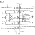
- Fig. 1 is one of the first and second differentials 4, 5 preferably used by the invention for use in a transmission 1 according to the invention with a freewheel function between its input shaft 2 and output shaft 3, which are surrounded in the transmission 1 by a housing 6 and thereby protected from the environment are.
- first and second differentials 4, 5 can be structurally identical. This, for example, simplifies warehousing and procurement of spare parts, etc.
- the differential 4; 5 preferably not constructed with bevel gears, but with crown gears 7, 8. These sit together with a planetary gear carrier 9 arranged between them on a common shaft 10; 11. However, not all of these are on shaft 10; 11 attached; rather, only one crown gear 7, 8 or the planetary gear carrier 9 on the shaft 10; 11 a fastening 12, the other two elements are only rotatably mounted there, in particular by means of roller bearings 13, 14.
- the shaft 10; 11 itself is rotatably mounted for its part, in particular on the housing 6 or on one or more chassis parts 15, 16 connected thereto.
- Rolling bearings 17, 18 are also preferably used for this purpose.
- the two crown gears 7, 8 are aligned parallel to one another and are provided with internal teeth on their mutually facing sides 19, 20, which in the rather schematic Fig. 1 is not explicitly reproduced.
- the planetary gear carrier 9 which, for example, has one or more radial to the shaft 10; 11 extending axles 21, on each of which at least one spur-toothed planetary gear 22, 23 is rotatably mounted, in particular by means of roller bearings 24, 25.
- the two face gears 7, 8 of a differential 4, 5 are preferably identical in construction, i.e. they have the same dimensions and the same number of teeth.
- both crown gears 7, 8 rotate at the same speed and share the same speed with the planetary gear carrier 9.
- the planet gears 22, 23 do not rotate about their respective axes 21.
- the planet gears 22, 23 must rotate about their respective axes 21.
- the two crown gears 7, 8 each provide one with the relevant speed ⁇ 12 , ⁇ 13 ; ⁇ 22 , ⁇ 23 represent the revolving rotary connection of the relevant differential 4, 5 and can be provided with teeth on their outer circumference 24, 25 for non-rotatable coupling to another rotary element.
- crown gears or rotary connections 7, 8 can also be enlarged in terms of their circumference or lengthened in their axial extent or can be integrated or connected in a rotationally fixed manner with other gears and experience their input or output via the same.
- the planetary gear carrier 9 can be surrounded on its periphery by a type of rim, on the outer circumference 26 of which a toothing can be arranged, with which a further toothed rotating element can mesh.
- a toothing can be arranged, with which a further toothed rotating element can mesh.
- it is mostly a crown gear 7, 8 or the Umlaufradisme 9 directly with the relevant shaft 10; 11 connected 12 and therefore does not require any circumferential toothing.
- the waves 10; 11 of the two differentials 4, 5 are preferably parallel to one another, but are not in common alignment.
- a transmission 2 according to the invention Fig. 2 there is therefore a total of three shafts 2, 10, 11, all of which are parallel to one another. These shafts 2, 10, 11 can be supported in various ways. In the embodiment according to Fig. 2 they are each mounted in the region of their two ends in opposing walls 27, 28 of the housing 6; only one end of the input shaft 2 and the output shaft 3 is led out.
- a gear wheel is anchored in a rotationally fixed manner on the input shaft 2 as an input gear wheel 29, which meshes with an all-round toothing on the outer circumference 26 of the planetary gear carrier 30 of the first differential 4 and in this way transfers the drive power fed to the input shaft 2 to the planetary gear carrier 30 of the first differential 4 initiates.
- the planetary gear carrier 30 of the first differential consequently rotates at a speed ⁇ 11 .
- a swivel connector is 31-in Fig. 2 the left one - non-rotatably connected to a gear 33, which consequently rotates at speed ⁇ 12.
- the rotary connection 39 does not drive the output shaft 3 directly, but only via a pair of gears 40, 41 with gears of the same size, which results in a reversal of the direction of rotation.
- ⁇ A. ⁇ E.
- the output shaft 3 rotates at the same speed when the input shaft 2 rotates, while the input shaft 2 stops when the output shaft 3 is driven.
- the input shaft 2 when the output shaft 3 is rotating, the input shaft 2 does not have to stand still, but can rotate in the corresponding direction of rotation up to the speed specified by the gear ratio.
- gear 1 (4) has to Fig. 4 a slightly different way of working.
- the gearbox 1 (4) has two differentials 42 (4) and 118 (4) .
- One differential 42 (FIG. 4) has an epicyclic gear carrier 132 and two further rotary connections 133, 134; the other differential 118 (4) via an epicyclic gear carrier 135 and two further rotary connections 136, 137.
- the differential condition applies to each of these two differentials 42 (4) and 118 (4).
- the following applies to the differential 42 (4) (in this case the indices relate to the reference symbols of the rotary connections): ⁇ 132 1 ⁇ 2 * ⁇ 133 + ⁇ 134 .
- ⁇ 135 1 ⁇ 2 * ⁇ 136 + ⁇ 137 .
- the transmission 1 (4) also has a structural asymmetry in that both the planetary gear carrier 132 and a further rotary connection 134 of the differential 42 (4) are coupled to the other differential 118 (4) , while the remaining rotary connection 133 is coupled via the gears 109 and 110 absorbs the drive energy from the drive shaft 2 (4).
- the other differential 118 (4) is wired symmetrically, that is to say that its two rotary connections 136, 137, their internal gear rings with mesh with at least one planetary gear mounted in the planetary gear carrier 135, are coupled to the drive-side differential 42 (FIG. 4) , namely inverting in both coupling branches.
- the planetary gear carrier 135 of this output-side differential 118 (4) is non-rotatably coupled to the output shaft, which is also not shown, via a toothing on its outer circumference and a not shown, meshing gear, which is to be indicated by the arrow 111.
- This transmission 1 (4) already has two different operating states in its normal operation, that is to say without connecting the shafts 112, 113.
- This synchronous operating state is maintained as long as the transmission is not forced by a blockage of the output shaft to decouple the output speed ⁇ A from the input speed ⁇ E by transitioning to the second operating state.
- the transmission 1 (4) can thus fulfill the task of a torque converter, as used in automatic transmissions, in order to decouple the drive motor from the driven wheels when the vehicle is braked.
- the free-running function can generally be switched off.
- the two shafts 112, 113, on each of which a differential 42 (4) , 118 (4) is seated, are rotatably coupled to a rotating part of one of the two coupling branches between the two differentials 42 (4) , 118 (4) .
- the rotating part fixed in a rotationally fixed manner on a shaft 112, 113 is marked by a hatched circle 114.
- the planetary gear 132 of the drive-side differential 52 (FIG. 4) is coupled to the input-side shaft 112, and to the output-side shaft 113 a gearwheel 115 that is rotationally fixedly coupled to a rotary connection 137.
- each of the two shafts 112, 113 has a double-cranked area 116, 117 with an opposite one the main section of the respective transmission shaft 112, 113 on an eccentric course.
- This double cranked, eccentric area 116, 117 can only rotate about the axis of the respective shaft 112, 113 if a bearing accommodating it can rotate about this axis. If, on the other hand, such a bearing is pivoted away from the alignment with the relevant shaft 112, 113, which is necessary for this, the linkage 116, 117 can no longer rotate and blocks the respective coupling branch.
- the rotary connection 132 is blocked by adjusting the cranked area 117 on the shaft 113, the rotary connection 134 is also at a standstill.
- the planet carrier 132 rotates at half the opposite input speed ⁇ E on the shaft 2 (4)
- the rotary connection 136 accordingly rotates at half the input speed ⁇ E , in the same direction of rotation as the input shaft 2 (4) .
- Due to the stationary rotary connection 137, the planet carrier 135 rotates at a quarter of the speed on the input shaft: ⁇ A. 1 ⁇ 4 ⁇ E. .
- the transmission 1 (4) can be used, for example, in a motor vehicle as a mechanical torque converter, with forward and reverse gear and a clutch function.
- a further modified embodiment of a transmission 1 'according to the invention is shown. It can be seen that there is not only a first differential 4 'and a second differential 5' here, but also a third differential 42.
- the wiring of these three differentials 4 ', 5', 42 also differs slightly from the wiring described above:
- the coupling between the input shaft 2 'and the differential 4' is different in that in the gear 1 'the planetary gear carrier 30' is non-rotatably connected to the shaft 10 ', which also functions as the input shaft 2'.
- both the first differential 4 'and the second differential 5' are symmetrically wired in this arrangement, namely insofar as the planetary gear carrier 30 'of the first differential 4' is non-rotatably connected to the input shaft 2 ', so there is a power split there on the other two rotary connections 31 ', 32' take place, while in the case of the second differential 5 'the power branches reunite in the epicyclic gear carrier 34' there. Therefore, in this arrangement, the coupling between the second and third differentials 5 ', 42 is asymmetrical.
- the transmission 1 ′′ behaves similarly Fig. 6 which differs from the in Fig. 5 only differs in that the third differential 42 "is coupled” mirror-inverted “so to speak, namely in such a way that, in addition to the planetary gear carrier 44", a rotary connection 46 "is coupled to the non-inverting branch between the first and second differential 4", 5 ", while in the case of the transmission 1 'after Fig. 4 instead a rotary connection 45 was coupled to the inverting branch between the first and second differentials 4 ', 5'.
- the rotation speed ⁇ A to the output shaft 3 can magnitude by an arbitrary amount of the input shaft 2 ⁇ a be greater than the rotational speed ⁇ E" (free-wheeling) but not smaller than that (drive effect), as long as ⁇ e and ⁇ a have the same direction of rotation (only additive superposition).
- Gear 1 (5) to Fig. 7 has a total of four differentials 4 (5) , 5 (5) , 42 (5) , 118 (5) .
- the output stage coupled to the output shaft 3 (5) with the differentials 4 (5) and 5 (5) is largely identical to the gearbox 1 from Fig. 3 .
- the two remaining differentials 42 (5) , 118 (5) are connected upstream of this output stage.
- the latter are also doubly coupled to each other, but only with a reversal of the direction of rotation, like the gear arrangement 1 (4) in Fig. 4 .
- the power flow on the drive-side differential 42 (5) is not directed via the branch on the planetary gear carrier 132 (5) , which has a lower torque, but via the rotary connection 134 (5) and the gears 119 ( 5) , 120 (5) to the rotary connection 137 (5) on the differential 42 (5) .
- the planet carrier 30 (5) of the differential 4 (5) is driven more strongly than its rotary connection 31 (5) . Its rotary connection 32 (5) thus rotates faster than the rotary connection 31 (5) , and the energy is mainly transmitted to the output differential 5 (5) via the non-inverting coupling branch.
- the gear 1 (5) can be used as a freewheel gear, with the special feature that in freewheeling, a steady acceleration of the output shaft is possible through a pulling load. This is because a pulling load on the output shaft 3 (5) can accelerate the speeds within the transmission 1 (5) without the speed on the input shaft 2 (5) increasing as a result; rather, the energy is deflected at the input differential 42 (5) and fed back into the forward branch with the gears 119 (5) , 120 (5). Because all the gears of the gearbox 1 (5) remain in mesh, a drive torque on the input shaft 2 (5) can immediately be passed on to the output shaft 3 (5) in order to continue driving it when the pulling load ceases.
- Gear 1 (6) off Fig. 8 is very similar to gearbox 1 (5) Fig. 7 on.
- the output stage with the differentials 4 (6) and 5 (6) is identical, and the differential 118 (6) immediately upstream of these is also identical to the gearbox 1 (5) .
- Only the differential 42 (6) is coupled exactly the wrong way round as with the gearbox 1 (5) off Fig. 7 .
- the coupling gears between the two differentials 42 (6) , 118 (6) on the input side are each of the same size.
- Gear 1 (7) off Fig. 9 differs from gearbox 1 (6) Fig. 8 above all in that between the two input-side differentials 42 (7) , 118 (7) - as between the two output-side differentials 4 (7) , 5 (7) - a coupling branch with inverting speed is provided, and one in each case Coupling branch with a non-inverting speed.
- a coupling gear 35, 35 '35 "or some other rotating part of a coupling branch of a transmission 1, 1', 1", 1 (4) , 1 (5) , 1 (6) , 1 (7) on its own shaft 47, 47 ', 47 "non-rotatably fixed, on which preferably no other gear is mounted or attached.
- the shaft 47 is bent multiple times, similar to a crankshaft for a cylinder.
- the eccentric section 48 of this shaft 47 is passed through a circular disk 49, which in turn is rotatably mounted in a kind of pivotable ring bezel 50.
- the pivotable ring bezel 50 can, for example, have a flat shape, for example with a triangular base. However, one side 51 of this triangle can be designed in an arc shape and provided with a row of teeth 52. In the area of the tip 53 of the ring bezel 50 lying opposite the arcuate side 51, the latter is mounted pivotably about an axis 54 perpendicular to its plane. It can be pivoted about the axis 54 by means of a worm 57 driven by a motor 55, preferably via a gear 56, which extends along the curved side 51 of the ring bezel 50 and meshes with the row of teeth 52 there.
- the permissible pivoting movement 58 of the ring steady 50 is limited by two limit switches or buttons 59, 60 or contactless sensors, for example proximity switches. Upon contact, these limit switches or buttons 59, 60 or sensors open and therefore open the circuit for the motor 55 in the relevant direction of rotation.
- a motor contactor 61 connects at current-free switching coil 62 connects the two contacts of the motor 55 to the plus and minus poles of a voltage source 63 in such a way that the ring steady 50 is in the in Figure 10a The position shown moves where it strikes the limit switch 60 or is located in the area of a contactless sensor, as a result of which the relevant limit switch 60 or sensor interrupts the relevant motor circuit and thereby stops the motor 55.
- the switching coil 62 of the motor contactor 61 is connected to the voltage source 63 by actuating a pedal 64 or other switching means, the armature moves within the motor contactor 61 and closes another circuit via the motor 55, which now causes it to be reversed Voltage is supplied and runs in the opposite direction of rotation, therefore the ring steady 50 is pivoted in the other direction until it hits the limit switch 59, which interrupts the motor circuit and now stops the ring steady 50 in the other end position.
- the ring bezel 50 takes the position shown in FIG Figure 10a a. That area 65 of the cranked shaft 47 on which the coupling gear 47 is fixed is aligned with the center 66 of the circular disk 49, which is rotatably mounted in the circular recess of the ring bezel 50.
- the coupling gear 47 can rotate together with the cranked shaft 47 and the circular disk 49 supporting this within the ring steady 50 around the axis 66 - the power transmission between the first and second differential 4, 5 in the non-inverting branch with the Coupling gear 47 is not impaired; in particular, the freewheeling function can then also occur if an active, pulling load acts on the output shaft.
- the drive wheels can no longer run freely when the brake is actuated, but remain coupled to the motor and are braked by it, according to the so-called "motor brake".
- FIG. 11a and 11b Another mechanism is shown, with which, as an alternative to the mechanism according to the Figures 10a to 10c a coupling branch within a transmission 1, 1 ', 1 ", 1 (4) , 1 (5) , 1 (6) , 1 (7) according to the invention can be blocked in order to achieve the freewheeling effect in a transmission 1, 1', 1 according to the invention ", 1 (4) , 1 (5) , 1 (6) , 1 (7) to be suppressed or switched off.
- Both mechanisms each have a disk-shaped part 50, 50 'with a circular recess, in which a disk 49, 49' with a circular circumference is rotatably received about its center 66, 66 '. Both disks 49, 50 or 49 ', 50' of a mechanism lie in a common plane.
- the circular, rotatably mounted disk 49, 49 ' has a recess arranged eccentrically to its center 66, 66', in which an eccentric section 48, 48 'of the shaft 47, 47' to be controlled is rotatably received.
- the main section 65, 65 'of the shaft 47, 47' connected non-rotatably to the gear or rotating part of a coupling branch to be controlled runs perpendicular to the plane of the rotatable disk 49, 49 '.
- Both mechanisms have two different control states: In a first state, which corresponds to normal operation of the relevant transmission 1, 1 ', 1 ", 1 (4) , 1 (5) , 1 (6) , 1 (7) , the disk 50, 50' is set in such a way that that the center point 66, 66 'of the circular disc 49, 49' rotatably received therein lies exactly in alignment with the main section 65, 65 'of the shaft 47, 47'.
- the circular disc 49, 49 ' can be precisely positioned around this main section 65, 65 'of the shaft 47, 47' rotate, and consequently this is also possible for the eccentric section 48, 48 'of the shaft 47, 47' - the shaft 47, 47 'can rotate about its axis, the relevant coupling branch can transmit a rotary movement
- both coupling branches are active, the inherent freewheeling function of the transmission 1, 1 ', 1 ", 1 (4) , 1 (5) , 1 (6) , 1 (7) according to the invention is active.
- the mechanics according to the Figures 11a and 11b differs from the mechanics according to the Figures 10a and 10b strictly speaking, only in the way in which the disk 50, 50 'is adjusted. While the adjustment of the disc 50 in the mechanics according to the Figures 10a and 10b is a pivoting movement about an axis 54 which is parallel to the main portion 65 of the shaft 47, the disc 50 'after the Figures 11a and 11b linearly shifted within their plane.
- a linear guide is provided instead of the rotary bearing around the axis 54, in the embodiment shown by means of two mutually parallel guide rods 121a, 121b, each of which penetrates a guide opening 122a, 122b in the guide disk 50 '.
- the two guide openings 122a, 122b run within the plane of the guide disk 50 'and parallel to this plane. You penetrate the guide disk 50 'preferably completely, in the embodiment according to the Figures 11a and 11b from a lower part of the transmission chassis 123 to an upper frame part 124, where they are each fixed and thereby rigidly connect the frame part 124 to the transmission chassis 123.
- the upper frame part 124 connects the two guide rods 121a, 121b to one another in the manner of a yoke.
- a through hole 125 is provided through which an output shaft 126 of a control motor 127 protrudes, the housing of which is fixed to the frame part 124 or transmission chassis 123.
- the output shaft 126 is preferably designed as a threaded spindle or is connected to such a spindle.
- the thread of this spindle is screwed into a bore 128 of the guide disk 50 'provided with an internal thread and is screw-adjustable.
- the threaded spindle screws itself into or out of the threaded bore 126, depending on the direction of rotation of the motor output shaft 126.
- control motor 127 Since the control motor 127 is fixed immovably on the frame part 124 or transmission chassis 123, the output shaft 126 cannot move along its longitudinal direction or along its axis of rotation 129; rather, the guide disk 50 ′ is adjusted via its internal thread bore 126 like a screw nut along the spindle axis 129, that is to say in the arrangement according to Figure 11a raised or lowered.
- the guide disk 50 ' By activating the control motor 127, the guide disk 50 'can now be adjusted along the guide rods 121a, 121b, for example lowered into the position shown in FIG Figure 11a position indicated by dashed lines. There the center point 66 'of the turntable 49' is no longer on the axis of rotation 65 'of the shaft 47', but below the same. This is possible in that the eccentric section 48 'of the shaft 47' is pivoted along a circular path 131 about the axis of rotation 65 '.
- Fig. 12 the drive train 67 of a vehicle with two driven wheels 68 is shown schematically, it being immaterial for the invention whether the front or rear wheels are driven.
- the drive energy is generated in a vehicle engine 69 and transformed in a downstream transmission 70 - preferably a manual transmission - into a speed range adapted to the respective driving situation.
- the transmission 70 can be any conceivable type of transmission, e.g. B. also to an automatic transmission or a continuously variable transmission.
- a transmission 1 according to the invention with a freewheeling function is switched on, in such a way that the driven Wheels 68 can turn faster than the output of the drive 70, but not slower.
- the wheels 68 are driven via the freewheel gear 1; However, if the driver takes his foot off the accelerator while the vehicle is rolling, the otherwise driven wheels 68 can run freely and "overtake” the engine speed, so to speak. The vehicle continues to roll without braking, while the driver reduces the engine speed to the idle speed without disengaging the clutch and without shifting to idle.
- Fig. 13 the drive train 67 'of an all-wheel drive vehicle is shown.
- the two front wheels 68 ' are coupled to one another by a differential 71', and so are the rear wheels 68 'to one another.
- Each of these differentials 71 ' are connected via a cardan shaft 72 to a central torque distributor 73, which in turn is driven by the motor 69' via a gearbox 70 '.
- a transmission 1 according to the invention with a freewheel function is switched on, in each case in such a way that the input shaft 2 faces the torque distributor and the output shaft faces the respective differential 71 '.
- the wheels 68 ' can rotate faster than the cardan shafts 72 coupled to the central torque distributor 73 if required that fuel can be saved.
- the motor 69 ' remains in continuous coupling with the wheels 68', so that the vehicle can immediately accelerate again when the accelerator pedal is pressed.
- the in Fig. 14 The shown drive train 67 ′′ of another vehicle with all-wheel drive differs from the one described above only in that a transmission 1 according to the invention is switched on only in one cardan shaft 72, but not in the other.
- a transmission according to the invention can replace a center differential that is otherwise necessary for all-wheel drive.
- Fig. 15 the circuit arrangement 74 of a vehicle is shown schematically with two wheels 78 driven by an electric motor 75 - possibly via a gearbox 76 and a differential 77, preferably the front wheels 78.
- the electric motor 75 is fed from an accumulator 79.
- the accumulator 79 can be charged or recharged by a generator 80, which in turn is rotatably coupled to a flywheel 81 for the purpose of energy absorption.
- the flywheel 81 is in turn coupled to the rear wheels 78 via a deflection gear 82, a gear 1 according to the invention with a freewheel function and a clutch 83 and, if necessary, a transmission gear 85 and a differential 86.
- the transmission 1 is connected in such a way that its input shaft 2 faces the differential 86, while its output shaft 3 faces the flywheel 81, so that when the vehicle is rolling and the clutch 84 is closed, the flywheel 81 is driven until it rotates at least at the same speed like the clutch 84; if, on the other hand, the vehicle slows down, the flywheel 81 is not braked by it thanks to the freewheel function according to the invention.
- the flywheel 81 can only be driven via the vehicle wheels 78, which is also the case for the embodiments according to the Figures 16 and 17 applies.
- the flywheel 81 can also be coupled via a further shaft 87 to a propeller 88 in the front area of the vehicle and can also be set in rotation by the propeller when it is blown against by wind 89 or airflow.
- the axis 90 of the flywheel 81 runs horizontally and transversely to the direction of travel in the example shown; the flywheel 81 can be located, for example, in the vertical central longitudinal plane 91 of the vehicle.
- the coupling of drive energy takes place via the differential 86 from one side of the flywheel 81, the coupling of drive energy from the propeller 88, however, takes place on the opposite side of the flywheel 81. This must therefore have two bevel gears.
- the circuit arrangement 74' according to Fig. 16 any drive energy initially combined and then introduced only on a single side of the flywheel 81 '.
- the bevel gear 92 which is not directly connected to the flywheel 81 'and whose axis of rotation runs in the direction of travel, is arranged on a shaft 93 which protrudes beyond the bevel gear 92 in and against the direction of travel within the framework of the deflecting gear 82'.
- the output shaft 3 of a transmission 1 according to the invention is connected to each end of this shaft 93.
- the input shaft 2 of the rear freewheel gear 1 is as in the arrangement according to Fig. 15 via a clutch 84 ', a transmission gear 85' and a differential 86 ' coupled to the rear wheels 78 '.
- the input shaft 2 of the front freewheel gear 1 seen in the direction of travel is coupled to the shaft 87 'of the propeller 88' via a further transmission gear 83.
- the shaft 93 between the two freewheel gears 1 according to the invention always rotates at least at the faster speed of the two gear input shafts 2 and communicates this speed to the flywheel 81 ', which can even run faster than these two gearboxes if required.
- Input shafts 2 for example when the vehicle is stationary.
- the flywheel 81 'always rotates at a maximum speed and supplies the generator 80' with mechanical energy in order to continuously generate current for charging the battery 79 '.
- the drive of the front wheels 78 ′′ by an electric motor 75 ′′ via a gear 76 ′′ and a differential 77 ′′ can be identical to the two previously described shift arrangements 74, 74 ′.
- the coupling of the rear wheels 78 ′′ via a differential 86 ′′, transmission gear 85 ′′, clutch 84 ′′, a freewheel gear 1 according to the invention and a shaft 93 ′′ is basically identical to the embodiments according to FIG Fig. 15 or 16 , although the shaft 93 ′′ is made longer in this case.
- the coupling of the generator 80 ′′ to the flywheel 81 ′′ and the supply of energy to the accumulator 79 ′′ is basically the same as in the previously described circuit arrangements 74, 74 ′.
- the flywheel 81 ′′ itself is equipped on its periphery with blades 94, similar to a water wheel Blades are exposed to the wind 89 or the airstream, which is possibly reinforced by the propeller 88 ′′ and / or directed onto the blades 94.
- the wind energy can be fed directly to the flywheel 81 ′′, whereby friction losses are minimized.
- the flywheel 81 ′′ can also be installed horizontally, that is to say with a vertically oriented axis of rotation 95. This case is shown in FIG Fig. 18 shown.
- Fig. 18 a plan view of the engine compartment 96 of a motor vehicle 97 with the hood folded up or removed; on the left edge of Fig. 18 the windshield 98 can be seen.
- air inlet ducts 100 are arranged on the front 99 of the vehicle 97, which deflect the incoming wind 89 sideways, in such a way that the air flow does the flywheel 81 "in the area of its blades 94 is fed approximately tangentially.
- a specific direction of rotation 101 of the flywheel 81 ′′ is specified.
- the shaft 93 ′′ could run in or along the vertical vehicle longitudinal center plane 91 ′′ below the vehicle floor or in a tunnel forwards up to the vertical axis of rotation 95.
- the current generated with the generator 80 "also connected to the horizontally built-in flywheel 81" can either be fed into the accumulator 89 "or used for brief charging of power capacitors 102.
- FIG. 19 Another advantageous application of the invention is in Fig. 19 shown.
- a freewheel gear 1 according to the invention can be seen there, whose input shaft 2 is coupled to an electric starter 104, preferably by means of a transmission gear 103.
- the output shaft 3 of the transmission 1 is - preferably via intermeshing gears 105, 106 - coupled non-rotatably to a shaft 107 on which a wheel 108 is attached.
- the wheel 108 can be, for example, a belt pulley for the V-belt of a motor vehicle, which is coupled to the crankshaft so that the relevant engine can be started with the starter 104; however, other applications are also conceivable;
- the wheel 108 could also be designed as a flywheel or flywheel, or the like.
- the advantage of the arrangement after Fig. 19 is that the starter 104 can remain permanently coupled to the driven shaft 107 or the driven wheel 108 via the transmission 1 according to the invention. If he has accelerated this (s) sufficiently, the starter 104 can simply be switched off, and thanks to the freewheeling function of the transmission 1 according to the invention, the shaft 107 and the wheel 108 are not braked, but continue to run freely. In this way, complex, wear-prone and failure-prone clutches can be avoided.
Landscapes
- Engineering & Computer Science (AREA)
- General Engineering & Computer Science (AREA)
- Mechanical Engineering (AREA)
- Retarders (AREA)
Claims (13)
- Mécanisme de roue libre (1, 1', 1", 1(4), 1(5), 1(6), 1(7)) comprenanta) un arbre d'entrée (2) rotatif avec une vitesse de rotation d'entrée (ωE);b) un arbre de sortie (3) rotatif avec une vitesse de rotation de sortie (ωA) ;c) un premier différentiel (4) interposé, comprenant au moins une roue satellite (22, 23) dentée, montée à rotation dans un premier porte-satellites (30), ladite roue satellite s'engrenant avec deux couronnes dentées internes au niveau de deux autres raccords tournants (31, 32) du premier différentiel (4), dont les vitesses de rotation (ω12, ω13) déterminent la vitesse de rotation (ω11) du premier porte-satellites (30) dans le premier différentiel (4) comme suit : ω11 = ½ * (ω12 +ω13) ;d) un deuxième différentiel (5) comprenant au moins une roue satellite (22, 23) dentée, montée à rotation dans un second porte-satellites (34), ladite roue satellite s'engrenant avec deux couronnes dentées internes au niveau de deux autres raccords tournants (38, 39) du deuxième différentiel (5), dont les vitesses de rotation (ω22, ω23) déterminent la vitesse de rotation (ω21) du second porte-satellites (34) dans le deuxième différentiel (5) comme suit : ω21 = ½ * (ω22 +ω23) ;e) en ce qu'au moins un porte-satellites (30, 34) du premier ou du deuxième différentiel (4, 5) n'est couplé ou intégré ni à l'arbre d'entrée (2) ni à l'arbre de sortie (3) ;f) en ce qu'un raccord tournant (31, 32) du premier différentiel (4), dont la couronne dentée interne s'engrène avec au moins une roue satellite (22, 23) du premier différentiel (4), est couplé à l'un des trois raccords tournants (34, 38, 39) du deuxième différentiel (5) de telle sorte que ces deux raccords tournants (22, 23 ; 34, 38, 39) couplés entre eux tournent à la même vitesse de rotation et dans le même sens de rotation ;g) en ce que les deux raccords tournants (22, 23 ; 34, 38, 39) couplés entre eux du premier et du deuxième différentiel (4, 5), lesquels en raison de leur couplage tournent à la même vitesse de rotation et dans le même sens de rotation, ne sont couplés ou intégrés ni à l'arbre d'entrée (2) ni à l'arbre de sortie (3) ;h) et en ce qu'un autre raccord tournant (31, 32) du premier différentiel (4) dont la couronne dentée interne s'engrène avec au moins une roue satellite (22, 23) du premier différentiel (4), est couplé à un autre des trois raccords tournants (34, 38, 39) du deuxième différentiel (5) de telle sorte que ces deux raccords tournants (30, 31 ; 34, 38, 39) couplés entre eux tournent à des vitesses de rotation diamétralement opposées, caractérisé en ce qu'i) un ou deux ou tous les différentiels (4 ; 5 ; 42) sont conçus avec un arbre continu (10 ; 11) qui est monté à rotation au niveau de ses deux extrémités dans un boîtier (6) et qui est couplé à l'une des trois parties rotatives (30, 31, 32 ; 34, 38, 39) coaxiales les unes par rapport aux autres, donc au porte-satellites (30, 34) ou à l'un des deux raccords tournants (31, 32 ; 38, 39) du différentiel concerné (4 ; 5 ; 42) de telle sorte qu'il tourne simultanément avec celui-ci tandis que les deux autres parties rotatives (30, 31, 32 ; 34, 38, 39) du différentiel concerné (4 ; 5 ; 42) sont montées à rotation sur l'arbre continu.
- Mécanisme de roue libre (1, 1', 1', 1", 1(4), 1(5), 1(6), 1(7)) selon la revendication 1, caractérisé en ce qu'un ou deux ou tous les différentiels (4 ; 5 ; 42) sont montés avec des roues dentées coniques (7, 8) ou des roues coniques.
- Mécanisme de roue libre (1, 1', 1", 1(4), 1(5), 1(6), 1(7)) selon l'une des revendications précédentes, caractérisé en ce qu'un réglage est effectué selon un rapport de réduction fixe ü = ωA/ωE de sorte que la vitesse de rotation de sortie (ωA) soit :

- Mécanisme de roue libre (1, 1', 1', 1", 1(4), 1(5), 1(6), 1(7)) selon la revendication 3, caractérisé en ce que pour un couple d'entraînement externé sur l'arbre de sortie (3) ou sur au moins un raccord tournant (34, 38, 39) du deuxième différentiel (5) dans le sens de rotation de sortie respectif s'applique :

- Mécanisme de roue libre (1, 1', 1', 1", 1(4), 1(5), 1(6), 1(7)) selon l'une des revendications précédentes, caractérisé par un premier couplage à rotation entre respectivement un raccord tournant (32, 33 ; 38, 39 ; 43, 45) non couplé au porte-satellite (30 ; 34) respectif de deux différentiels (4 ; 5 ; 42) différents, de préférence du premier et du deuxième différentiel (4,5), en particulier de telle sorte que leurs vitesses de rotation sont identiques.
- Mécanisme de roue libre (1, 1', 1", 1(4), 1(5), 1(6), 1(7)) selon l'une des revendications précédentes, caractérisé par un second couplage à rotation entre deux différentiels (4 ; 5 ; 42) différents, en particulier de telle sorte que les vitesses de rotation des raccords tournants couplés entre eux (30, 32, 33 ; 34, 38, 39 ; 43, 44, 45) sont identiques en sens opposé.
- Mécanisme de roue libre (1, 1', 1', 1", 1(4), 1(5), 1(6), 1(7)) selon l'une des revendications précédentes, caractérisé en ce que l'arbre d'entrée (2) est couplé au premier différentiel (4), de préférence de manière symétrique, c'est-à-dire en particulier seulement à son porte-satellites (30)
- Mécanisme de roue libre (1, 1', 1',1", 1(4), 1(5), 1(6), 1(7)) selon l'une des revendications précédentes, caractérisé en ce que l'arbre de sortie (3) est couplé au deuxième différentiel (5), de préférence de manière asymétrique, c'est-à-dire de préférence pas ou pas seulement à son porte-satellites (34), mais le cas échéant aussi à un raccord tournant (38, 39) du deuxième différentiel (5) dont la couronne dentée interne s'engrène avec au moins une roue satellite dentée (22, 23).
- Mécanisme de roue libre (1, 1', 1', 1", 1(4), 1(5), 1(6), 1(7)) selon l'une des revendications précédentes, caractérisé en ce que l'arbre de sortie (3) est couplé à un troisième différentiel (42), en ce que de préférence le troisième différentiel (42) est couplé au deux raccords tournants (34, 38, 39) du deuxième différentiel (5), de préférence de manière asymétrique, par conséquent à son porte-satellites (34) d'une part ainsi qu'à un raccord tournant (38, 39) du deuxième différentiel (5), dont la couronne dentée interne s'engrène avec au moins une roue satellite dentée (22, 23) du deuxième différentiel (5).
- Mécanisme de roue libre (1, 1', 1", 1(4), 1(5), 1(6), 1(7)) selon l'une des revendications précédentes, caractérisé en ce qu'au moins l'un des deux raccords tournants (30, 31), qui est couplé au deuxième différentiel (5), du premier différentiel (4) reste non influencé de l'extérieur, afin que sa vitesse de rotation (ω12 , ω13) puisse être librement réglée, en particulier diamétralement opposée à l'autre raccord tournant (30, 31), qui est couplé au deuxième différentiel (5), du premier différentiel (4), le cas échéant en plus de la double vitesse de rotation (ω11) du premier porte-satellites (30) lorsqu'un couple d'entraînement appliqué dans son sens de rotation agit sur l'arbre de sortie (3) et/ou sur au moins un raccord tournant (34, 38, 39) du deuxième différentiel (5), de telle sorte que la vitesse de rotation de sortie (ωA) peut augmenter sous l'effet de ce couple d'entraînement, sans avoir d'incidence sur la vitesse de rotation d'entrée (ωE).
- Mécanisme de roue libre (1, 1', 1', 1", 1(4), 1(5), 1(6), 1(7)) selon l'une des revendications précédentes, caractérisé en ce qu'en agissant sur une seule roue dentée de couplage (35) entre le premier et le deuxième différentiel (4, 5) la fonction roue libre est désactivée, de préférence en mettant la roue dentée de couplage (35) concernée dans un état non rotatif pour désactiver la fonction roue libre, en ce qu'en particulier la roue dentée de couplage (35) est fixée sur un arbre (47) plusieurs fois coudé, qui à son tour est monté excentriquement dans au moins un disque (49), lequel à son tour est logé à rotation dans une lunette annulaire (50) susceptible de pivoter et/ou déplaçable.
- Mécanisme de roue libre (1, 1', 1', 1", 1(4), 1(5), 1(6), 1(7)) selon l'une des revendications précédentes, caractérisé en ce qu'au moins un couplage entre le premier différentiel (4) et le deuxième différentiel (5), de préférence le couplage dont les raccords tournants (22, 23 ; 34, 38, 39) couplés entre eux du premier et du deuxième différentiel (4, 5) en raison de ce couplage tournent à la même vitesse de rotation et dans le même sens de rotation, en particulier les deux couplages entre ces différentiels (4, 5), ni accessible(s) ni influençable(s) de l'extérieur, ainsi que de préférence au plus au niveau interne par l'intermédiaire d'une lunette annulaire (50) susceptible de pivoter et/ou déplaçable, laquelle coopère avec une zone d'un arbre (47) plusieurs fois coudé d'une roué dentée (35, 36, 37) du couplage concerné qui est excentrique par rapport à l'axe de rotation de cette roue dentée (35, 36, 37).
- Groupe motopropulseur d'un véhicule comprenant un mécanisme de roue libre (1, 1', 1', 1", 1(4), 1(5), 1(6), 1(7)) selon l'une des revendications précédentes, caractérisé en ce que le mécanisme de roue libre est connecté dans le groupe motopropulseur (67) de telle sorte qu'en régime de décélération la fonction roue libre découple le moteur d'entraînement (69) du groupe motopropulseur (67) par rapport aux roues (68), et/ou qu'il est connecté entre le groupe motopropulseur (67) et un volant d'inertie (81), et ou qu'il est connecté entre le groupe motopropulseur (67) et un démarreur (104) ou entre un volant d'inertie (81) et un démarreur (104).
Applications Claiming Priority (1)
| Application Number | Priority Date | Filing Date | Title |
|---|---|---|---|
| DE102015003750.1A DE102015003750A1 (de) | 2015-03-25 | 2015-03-25 | Freilaufmechanik |
Publications (2)
| Publication Number | Publication Date |
|---|---|
| EP3073149A1 EP3073149A1 (fr) | 2016-09-28 |
| EP3073149B1 true EP3073149B1 (fr) | 2021-05-05 |
Family
ID=55527216
Family Applications (1)
| Application Number | Title | Priority Date | Filing Date |
|---|---|---|---|
| EP16000573.2A Active EP3073149B1 (fr) | 2015-03-25 | 2016-03-09 | Mécanisme de roue libre |
Country Status (2)
| Country | Link |
|---|---|
| EP (1) | EP3073149B1 (fr) |
| DE (1) | DE102015003750A1 (fr) |
Families Citing this family (3)
| Publication number | Priority date | Publication date | Assignee | Title |
|---|---|---|---|---|
| CN112144240B (zh) * | 2019-06-27 | 2022-05-03 | 青岛海尔洗衣机有限公司 | 一种洗衣机减速离合装置 |
| CN110299798B (zh) * | 2019-06-28 | 2024-10-22 | 宁波创跃园林工具有限公司 | 用于电动园林工具的驱动机构 |
| WO2023105499A1 (fr) | 2021-12-10 | 2023-06-15 | Nazif Kama | Mécanisme de roue libre comprenant un arbre |
Family Cites Families (15)
| Publication number | Priority date | Publication date | Assignee | Title |
|---|---|---|---|---|
| FR516793A (fr) * | 1920-06-01 | 1921-04-26 | Pierre Day | Dispositif assurant automatiquement et progressivement l'utilisation de la totalité de la puissance d'un moteur demeurant à un régime constant, quel que soit l'effort résistant |
| US2187843A (en) * | 1938-02-21 | 1940-01-23 | Alfred H Rzeppa | Driving axle |
| US2786369A (en) * | 1953-02-06 | 1957-03-26 | Howard W Simpson | Planetary transmission |
| DE1111954B (de) | 1954-08-23 | 1961-07-27 | Ferguson Res Ltd Harry | Getriebeanordnung fuer ein Getriebesystem eines Motorfahrzeuges |
| DE1121939B (de) * | 1959-09-04 | 1962-01-11 | Alexander Schwarz Dipl Ing | Stufenlos regelbares Getriebe, insbesondere fuer Kraftfahrzeuge |
| US3119282A (en) * | 1961-01-31 | 1964-01-28 | Douglas D Raze | Variable speed power transmission |
| US3645152A (en) * | 1970-04-27 | 1972-02-29 | Behzat Olcer | Variable speed mechanism |
| FR2098864A5 (fr) * | 1970-07-20 | 1972-03-10 | Godec Robert | |
| US5033996A (en) * | 1988-09-12 | 1991-07-23 | Heinz Frey | Continuously variable drive |
| DE4205260C1 (en) * | 1992-02-21 | 1993-04-08 | Ulrich Von 4224 Huenxe De Mallinckrodt | Continuously variable transmission drive - has input torque branched under set ratio and again brought together, one branch producing additional torque |
| DE10125793C2 (de) * | 2001-05-26 | 2003-08-07 | Gkn Automotive Gmbh | Differentialgetriebe mit integrierten Gleichlaufgelenken |
| DE10308800A1 (de) * | 2003-02-27 | 2004-09-09 | Daimlerchrysler Ag | Kronenraddifferential bzw. Satz von zumindest zwei Kronenraddifferentialen |
| US7462124B2 (en) * | 2003-09-08 | 2008-12-09 | Differential Dynamics Corporation | Variable motion control device and method of use |
| CN201434055Y (zh) * | 2008-09-18 | 2010-03-31 | 孟良吉 | 全齿轮速度自适应无级变速器 |
| DE102012018190A1 (de) * | 2012-09-10 | 2014-05-15 | Talip Tevkür | Drehzahlwandler |
-
2015
- 2015-03-25 DE DE102015003750.1A patent/DE102015003750A1/de not_active Withdrawn
-
2016
- 2016-03-09 EP EP16000573.2A patent/EP3073149B1/fr active Active
Also Published As
| Publication number | Publication date |
|---|---|
| DE102015003750A1 (de) | 2016-09-29 |
| EP3073149A1 (fr) | 2016-09-28 |
Similar Documents
| Publication | Publication Date | Title |
|---|---|---|
| EP2134564B1 (fr) | Boite de transfert pour vehicules a moteur | |
| DE102012100865B4 (de) | Antriebsanordnung mit elektrischer Maschine und Kraftfahrzeug mit einer solchen Antriebsanordnung | |
| EP2659165B1 (fr) | Transmission à dérivation de puissance | |
| EP3003766B1 (fr) | Dispositif différentiel central pour un système d'entraînement de véhicule automobile | |
| EP2577097B1 (fr) | Système de transmission | |
| EP1792104A2 (fr) | Ensemble differentiel a repartition du couple et du regime commandable | |
| EP3037692B1 (fr) | Boîte de vitesses à division de puissance pour un véhicule automobile | |
| EP2253867A1 (fr) | Engrenage d'embrayage à division de puissance | |
| WO2016062384A1 (fr) | Dispositif d'entraînement pour un véhicule à moteur, véhicule à moteur et procédé permettant de faire fonctionner un véhicule à moteur | |
| EP1626206A2 (fr) | Transmission à division de puissance pour véhicules automobiles | |
| DE112016006924B4 (de) | Elektroantriebsanordnung und Antriebsstrang mit einer solchen Elektroantriebsanordnung | |
| WO2009127324A2 (fr) | Agencement d'essieu moteur d'un véhicule avec boîte de transfert | |
| EP1561971B1 (fr) | Dispositif d'entraînement | |
| EP0528319A1 (fr) | Transmission pour véhicules avec différentiel central | |
| EP0818643B1 (fr) | Transmission hydromécanique à division de puissance | |
| EP3073149B1 (fr) | Mécanisme de roue libre | |
| DE102021210740B3 (de) | Getriebe für ein Fahrzeug sowie Antriebsstrang mit einem solchen Getriebe | |
| WO2015173628A1 (fr) | Engrenage différentiel à déverrouillage automatique | |
| WO2007138001A1 (fr) | Unité de transmission destinée à transmettre un couple d'entraînement d'un arbre d'entrée à deux arbres de sortie | |
| EP2861445B1 (fr) | Démultiplicateur et différentiel et unité à motoréducteur | |
| DE60317975T2 (de) | Stufenloses Getriebe für Kraftfahrzeuge, insbesondere für landwirtschaftliche Traktoren | |
| WO2023104414A1 (fr) | Système d'entrainement électrique pour un véhicule automobile | |
| WO2012146352A1 (fr) | Dispositif d'entraînement pour un véhicule automobile à traction avant, arrière ou intégrale | |
| DE3733152C2 (fr) | ||
| EP3423736B1 (fr) | Transmission différentielle de véhicule automobile |
Legal Events
| Date | Code | Title | Description |
|---|---|---|---|
| PUAI | Public reference made under article 153(3) epc to a published international application that has entered the european phase |
Free format text: ORIGINAL CODE: 0009012 |
|
| AK | Designated contracting states |
Kind code of ref document: A1 Designated state(s): AL AT BE BG CH CY CZ DE DK EE ES FI FR GB GR HR HU IE IS IT LI LT LU LV MC MK MT NL NO PL PT RO RS SE SI SK SM TR |
|
| AX | Request for extension of the european patent |
Extension state: BA ME |
|
| STAA | Information on the status of an ep patent application or granted ep patent |
Free format text: STATUS: REQUEST FOR EXAMINATION WAS MADE |
|
| 17P | Request for examination filed |
Effective date: 20170328 |
|
| RBV | Designated contracting states (corrected) |
Designated state(s): AL AT BE BG CH CY CZ DE DK EE ES FI FR GB GR HR HU IE IS IT LI LT LU LV MC MK MT NL NO PL PT RO RS SE SI SK SM TR |
|
| STAA | Information on the status of an ep patent application or granted ep patent |
Free format text: STATUS: EXAMINATION IS IN PROGRESS |
|
| 17Q | First examination report despatched |
Effective date: 20180514 |
|
| RIC1 | Information provided on ipc code assigned before grant |
Ipc: F16H 3/74 20060101AFI20200928BHEP Ipc: F16H 63/34 20060101ALI20200928BHEP Ipc: F16H 63/06 20060101ALI20200928BHEP Ipc: F16H 48/08 20060101ALN20200928BHEP |
|
| GRAP | Despatch of communication of intention to grant a patent |
Free format text: ORIGINAL CODE: EPIDOSNIGR1 |
|
| STAA | Information on the status of an ep patent application or granted ep patent |
Free format text: STATUS: GRANT OF PATENT IS INTENDED |
|
| RIC1 | Information provided on ipc code assigned before grant |
Ipc: F16H 48/08 20060101ALN20201022BHEP Ipc: F16H 63/34 20060101ALI20201022BHEP Ipc: F16H 3/74 20060101AFI20201022BHEP Ipc: F16H 63/06 20060101ALI20201022BHEP |
|
| INTG | Intention to grant announced |
Effective date: 20201111 |
|
| GRAS | Grant fee paid |
Free format text: ORIGINAL CODE: EPIDOSNIGR3 |
|
| GRAA | (expected) grant |
Free format text: ORIGINAL CODE: 0009210 |
|
| STAA | Information on the status of an ep patent application or granted ep patent |
Free format text: STATUS: THE PATENT HAS BEEN GRANTED |
|
| AK | Designated contracting states |
Kind code of ref document: B1 Designated state(s): AL AT BE BG CH CY CZ DE DK EE ES FI FR GB GR HR HU IE IS IT LI LT LU LV MC MK MT NL NO PL PT RO RS SE SI SK SM TR |
|
| REG | Reference to a national code |
Ref country code: GB Ref legal event code: FG4D Free format text: NOT ENGLISH |
|
| REG | Reference to a national code |
Ref country code: CH Ref legal event code: EP |
|
| REG | Reference to a national code |
Ref country code: AT Ref legal event code: REF Ref document number: 1390197 Country of ref document: AT Kind code of ref document: T Effective date: 20210515 |
|
| REG | Reference to a national code |
Ref country code: DE Ref legal event code: R096 Ref document number: 502016012942 Country of ref document: DE |
|
| REG | Reference to a national code |
Ref country code: IE Ref legal event code: FG4D Free format text: LANGUAGE OF EP DOCUMENT: GERMAN |
|
| REG | Reference to a national code |
Ref country code: LT Ref legal event code: MG9D |
|
| PG25 | Lapsed in a contracting state [announced via postgrant information from national office to epo] |
Ref country code: BG Free format text: LAPSE BECAUSE OF FAILURE TO SUBMIT A TRANSLATION OF THE DESCRIPTION OR TO PAY THE FEE WITHIN THE PRESCRIBED TIME-LIMIT Effective date: 20210805 Ref country code: HR Free format text: LAPSE BECAUSE OF FAILURE TO SUBMIT A TRANSLATION OF THE DESCRIPTION OR TO PAY THE FEE WITHIN THE PRESCRIBED TIME-LIMIT Effective date: 20210505 Ref country code: FI Free format text: LAPSE BECAUSE OF FAILURE TO SUBMIT A TRANSLATION OF THE DESCRIPTION OR TO PAY THE FEE WITHIN THE PRESCRIBED TIME-LIMIT Effective date: 20210505 Ref country code: LT Free format text: LAPSE BECAUSE OF FAILURE TO SUBMIT A TRANSLATION OF THE DESCRIPTION OR TO PAY THE FEE WITHIN THE PRESCRIBED TIME-LIMIT Effective date: 20210505 |
|
| PG25 | Lapsed in a contracting state [announced via postgrant information from national office to epo] |
Ref country code: LV Free format text: LAPSE BECAUSE OF FAILURE TO SUBMIT A TRANSLATION OF THE DESCRIPTION OR TO PAY THE FEE WITHIN THE PRESCRIBED TIME-LIMIT Effective date: 20210505 Ref country code: IS Free format text: LAPSE BECAUSE OF FAILURE TO SUBMIT A TRANSLATION OF THE DESCRIPTION OR TO PAY THE FEE WITHIN THE PRESCRIBED TIME-LIMIT Effective date: 20210905 Ref country code: GR Free format text: LAPSE BECAUSE OF FAILURE TO SUBMIT A TRANSLATION OF THE DESCRIPTION OR TO PAY THE FEE WITHIN THE PRESCRIBED TIME-LIMIT Effective date: 20210806 Ref country code: ES Free format text: LAPSE BECAUSE OF FAILURE TO SUBMIT A TRANSLATION OF THE DESCRIPTION OR TO PAY THE FEE WITHIN THE PRESCRIBED TIME-LIMIT Effective date: 20210505 Ref country code: NO Free format text: LAPSE BECAUSE OF FAILURE TO SUBMIT A TRANSLATION OF THE DESCRIPTION OR TO PAY THE FEE WITHIN THE PRESCRIBED TIME-LIMIT Effective date: 20210805 Ref country code: PL Free format text: LAPSE BECAUSE OF FAILURE TO SUBMIT A TRANSLATION OF THE DESCRIPTION OR TO PAY THE FEE WITHIN THE PRESCRIBED TIME-LIMIT Effective date: 20210505 Ref country code: PT Free format text: LAPSE BECAUSE OF FAILURE TO SUBMIT A TRANSLATION OF THE DESCRIPTION OR TO PAY THE FEE WITHIN THE PRESCRIBED TIME-LIMIT Effective date: 20210906 Ref country code: SE Free format text: LAPSE BECAUSE OF FAILURE TO SUBMIT A TRANSLATION OF THE DESCRIPTION OR TO PAY THE FEE WITHIN THE PRESCRIBED TIME-LIMIT Effective date: 20210505 Ref country code: RS Free format text: LAPSE BECAUSE OF FAILURE TO SUBMIT A TRANSLATION OF THE DESCRIPTION OR TO PAY THE FEE WITHIN THE PRESCRIBED TIME-LIMIT Effective date: 20210505 |
|
| REG | Reference to a national code |
Ref country code: NL Ref legal event code: MP Effective date: 20210505 |
|
| PG25 | Lapsed in a contracting state [announced via postgrant information from national office to epo] |
Ref country code: NL Free format text: LAPSE BECAUSE OF FAILURE TO SUBMIT A TRANSLATION OF THE DESCRIPTION OR TO PAY THE FEE WITHIN THE PRESCRIBED TIME-LIMIT Effective date: 20210505 |
|
| PG25 | Lapsed in a contracting state [announced via postgrant information from national office to epo] |
Ref country code: RO Free format text: LAPSE BECAUSE OF FAILURE TO SUBMIT A TRANSLATION OF THE DESCRIPTION OR TO PAY THE FEE WITHIN THE PRESCRIBED TIME-LIMIT Effective date: 20210505 Ref country code: SM Free format text: LAPSE BECAUSE OF FAILURE TO SUBMIT A TRANSLATION OF THE DESCRIPTION OR TO PAY THE FEE WITHIN THE PRESCRIBED TIME-LIMIT Effective date: 20210505 Ref country code: SK Free format text: LAPSE BECAUSE OF FAILURE TO SUBMIT A TRANSLATION OF THE DESCRIPTION OR TO PAY THE FEE WITHIN THE PRESCRIBED TIME-LIMIT Effective date: 20210505 Ref country code: DK Free format text: LAPSE BECAUSE OF FAILURE TO SUBMIT A TRANSLATION OF THE DESCRIPTION OR TO PAY THE FEE WITHIN THE PRESCRIBED TIME-LIMIT Effective date: 20210505 Ref country code: EE Free format text: LAPSE BECAUSE OF FAILURE TO SUBMIT A TRANSLATION OF THE DESCRIPTION OR TO PAY THE FEE WITHIN THE PRESCRIBED TIME-LIMIT Effective date: 20210505 Ref country code: CZ Free format text: LAPSE BECAUSE OF FAILURE TO SUBMIT A TRANSLATION OF THE DESCRIPTION OR TO PAY THE FEE WITHIN THE PRESCRIBED TIME-LIMIT Effective date: 20210505 |
|
| REG | Reference to a national code |
Ref country code: DE Ref legal event code: R097 Ref document number: 502016012942 Country of ref document: DE |
|
| PLBE | No opposition filed within time limit |
Free format text: ORIGINAL CODE: 0009261 |
|
| STAA | Information on the status of an ep patent application or granted ep patent |
Free format text: STATUS: NO OPPOSITION FILED WITHIN TIME LIMIT |
|
| 26N | No opposition filed |
Effective date: 20220208 |
|
| PG25 | Lapsed in a contracting state [announced via postgrant information from national office to epo] |
Ref country code: IS Free format text: LAPSE BECAUSE OF FAILURE TO SUBMIT A TRANSLATION OF THE DESCRIPTION OR TO PAY THE FEE WITHIN THE PRESCRIBED TIME-LIMIT Effective date: 20210905 Ref country code: AL Free format text: LAPSE BECAUSE OF FAILURE TO SUBMIT A TRANSLATION OF THE DESCRIPTION OR TO PAY THE FEE WITHIN THE PRESCRIBED TIME-LIMIT Effective date: 20210505 |
|
| PG25 | Lapsed in a contracting state [announced via postgrant information from national office to epo] |
Ref country code: IT Free format text: LAPSE BECAUSE OF FAILURE TO SUBMIT A TRANSLATION OF THE DESCRIPTION OR TO PAY THE FEE WITHIN THE PRESCRIBED TIME-LIMIT Effective date: 20210505 |
|
| PG25 | Lapsed in a contracting state [announced via postgrant information from national office to epo] |
Ref country code: MC Free format text: LAPSE BECAUSE OF FAILURE TO SUBMIT A TRANSLATION OF THE DESCRIPTION OR TO PAY THE FEE WITHIN THE PRESCRIBED TIME-LIMIT Effective date: 20210505 |
|
| REG | Reference to a national code |
Ref country code: CH Ref legal event code: PL |
|
| GBPC | Gb: european patent ceased through non-payment of renewal fee |
Effective date: 20220309 |
|
| REG | Reference to a national code |
Ref country code: BE Ref legal event code: MM Effective date: 20220331 |
|
| PG25 | Lapsed in a contracting state [announced via postgrant information from national office to epo] |
Ref country code: LU Free format text: LAPSE BECAUSE OF NON-PAYMENT OF DUE FEES Effective date: 20220309 Ref country code: LI Free format text: LAPSE BECAUSE OF NON-PAYMENT OF DUE FEES Effective date: 20220331 Ref country code: IE Free format text: LAPSE BECAUSE OF NON-PAYMENT OF DUE FEES Effective date: 20220309 Ref country code: GB Free format text: LAPSE BECAUSE OF NON-PAYMENT OF DUE FEES Effective date: 20220309 Ref country code: FR Free format text: LAPSE BECAUSE OF NON-PAYMENT OF DUE FEES Effective date: 20220331 Ref country code: CH Free format text: LAPSE BECAUSE OF NON-PAYMENT OF DUE FEES Effective date: 20220331 |
|
| PG25 | Lapsed in a contracting state [announced via postgrant information from national office to epo] |
Ref country code: BE Free format text: LAPSE BECAUSE OF NON-PAYMENT OF DUE FEES Effective date: 20220331 |
|
| REG | Reference to a national code |
Ref country code: AT Ref legal event code: MM01 Ref document number: 1390197 Country of ref document: AT Kind code of ref document: T Effective date: 20220309 |
|
| P01 | Opt-out of the competence of the unified patent court (upc) registered |
Effective date: 20230531 |
|
| PG25 | Lapsed in a contracting state [announced via postgrant information from national office to epo] |
Ref country code: AT Free format text: LAPSE BECAUSE OF NON-PAYMENT OF DUE FEES Effective date: 20220309 |
|
| PG25 | Lapsed in a contracting state [announced via postgrant information from national office to epo] |
Ref country code: HU Free format text: LAPSE BECAUSE OF FAILURE TO SUBMIT A TRANSLATION OF THE DESCRIPTION OR TO PAY THE FEE WITHIN THE PRESCRIBED TIME-LIMIT; INVALID AB INITIO Effective date: 20160309 |
|
| PG25 | Lapsed in a contracting state [announced via postgrant information from national office to epo] |
Ref country code: MK Free format text: LAPSE BECAUSE OF FAILURE TO SUBMIT A TRANSLATION OF THE DESCRIPTION OR TO PAY THE FEE WITHIN THE PRESCRIBED TIME-LIMIT Effective date: 20210505 Ref country code: CY Free format text: LAPSE BECAUSE OF FAILURE TO SUBMIT A TRANSLATION OF THE DESCRIPTION OR TO PAY THE FEE WITHIN THE PRESCRIBED TIME-LIMIT Effective date: 20210505 |
|
| PG25 | Lapsed in a contracting state [announced via postgrant information from national office to epo] |
Ref country code: MT Free format text: LAPSE BECAUSE OF FAILURE TO SUBMIT A TRANSLATION OF THE DESCRIPTION OR TO PAY THE FEE WITHIN THE PRESCRIBED TIME-LIMIT Effective date: 20210505 |
|
| PGFP | Annual fee paid to national office [announced via postgrant information from national office to epo] |
Ref country code: TR Payment date: 20250226 Year of fee payment: 10 |
|
| PGFP | Annual fee paid to national office [announced via postgrant information from national office to epo] |
Ref country code: DE Payment date: 20250602 Year of fee payment: 10 |