EP3073200A1 - Aiguillage hydraulique chauffe destine a l'integration de chaleur externe - Google Patents
Aiguillage hydraulique chauffe destine a l'integration de chaleur externe Download PDFInfo
- Publication number
- EP3073200A1 EP3073200A1 EP16162646.0A EP16162646A EP3073200A1 EP 3073200 A1 EP3073200 A1 EP 3073200A1 EP 16162646 A EP16162646 A EP 16162646A EP 3073200 A1 EP3073200 A1 EP 3073200A1
- Authority
- EP
- European Patent Office
- Prior art keywords
- heating
- hydraulic switch
- heating circuit
- heating system
- temperature
- Prior art date
- Legal status (The legal status is an assumption and is not a legal conclusion. Google has not performed a legal analysis and makes no representation as to the accuracy of the status listed.)
- Granted
Links
Images


Classifications
-
- F—MECHANICAL ENGINEERING; LIGHTING; HEATING; WEAPONS; BLASTING
- F24—HEATING; RANGES; VENTILATING
- F24D—DOMESTIC- OR SPACE-HEATING SYSTEMS, e.g. CENTRAL HEATING SYSTEMS; DOMESTIC HOT-WATER SUPPLY SYSTEMS; ELEMENTS OR COMPONENTS THEREFOR
- F24D3/00—Hot-water central heating systems
- F24D3/08—Hot-water central heating systems in combination with systems for domestic hot-water supply
- F24D3/082—Hot water storage tanks specially adapted therefor
-
- F—MECHANICAL ENGINEERING; LIGHTING; HEATING; WEAPONS; BLASTING
- F24—HEATING; RANGES; VENTILATING
- F24D—DOMESTIC- OR SPACE-HEATING SYSTEMS, e.g. CENTRAL HEATING SYSTEMS; DOMESTIC HOT-WATER SUPPLY SYSTEMS; ELEMENTS OR COMPONENTS THEREFOR
- F24D3/00—Hot-water central heating systems
- F24D3/10—Feed-line arrangements, e.g. providing for heat-accumulator tanks, expansion tanks ; Hydraulic components of a central heating system
- F24D3/1091—Mixing cylinders
-
- F—MECHANICAL ENGINEERING; LIGHTING; HEATING; WEAPONS; BLASTING
- F24—HEATING; RANGES; VENTILATING
- F24D—DOMESTIC- OR SPACE-HEATING SYSTEMS, e.g. CENTRAL HEATING SYSTEMS; DOMESTIC HOT-WATER SUPPLY SYSTEMS; ELEMENTS OR COMPONENTS THEREFOR
- F24D2200/00—Heat sources or energy sources
- F24D2200/04—Gas or oil fired boiler
-
- F—MECHANICAL ENGINEERING; LIGHTING; HEATING; WEAPONS; BLASTING
- F24—HEATING; RANGES; VENTILATING
- F24D—DOMESTIC- OR SPACE-HEATING SYSTEMS, e.g. CENTRAL HEATING SYSTEMS; DOMESTIC HOT-WATER SUPPLY SYSTEMS; ELEMENTS OR COMPONENTS THEREFOR
- F24D2200/00—Heat sources or energy sources
- F24D2200/06—Solid fuel fired boiler
-
- F—MECHANICAL ENGINEERING; LIGHTING; HEATING; WEAPONS; BLASTING
- F24—HEATING; RANGES; VENTILATING
- F24D—DOMESTIC- OR SPACE-HEATING SYSTEMS, e.g. CENTRAL HEATING SYSTEMS; DOMESTIC HOT-WATER SUPPLY SYSTEMS; ELEMENTS OR COMPONENTS THEREFOR
- F24D2200/00—Heat sources or energy sources
- F24D2200/16—Waste heat
- F24D2200/19—Fuel cells
-
- F—MECHANICAL ENGINEERING; LIGHTING; HEATING; WEAPONS; BLASTING
- F24—HEATING; RANGES; VENTILATING
- F24D—DOMESTIC- OR SPACE-HEATING SYSTEMS, e.g. CENTRAL HEATING SYSTEMS; DOMESTIC HOT-WATER SUPPLY SYSTEMS; ELEMENTS OR COMPONENTS THEREFOR
- F24D2200/00—Heat sources or energy sources
- F24D2200/32—Heat sources or energy sources involving multiple heat sources in combination or as alternative heat sources
-
- F—MECHANICAL ENGINEERING; LIGHTING; HEATING; WEAPONS; BLASTING
- F24—HEATING; RANGES; VENTILATING
- F24D—DOMESTIC- OR SPACE-HEATING SYSTEMS, e.g. CENTRAL HEATING SYSTEMS; DOMESTIC HOT-WATER SUPPLY SYSTEMS; ELEMENTS OR COMPONENTS THEREFOR
- F24D2220/00—Components of central heating installations excluding heat sources
- F24D2220/02—Fluid distribution means
- F24D2220/0235—Three-way-valves
-
- F—MECHANICAL ENGINEERING; LIGHTING; HEATING; WEAPONS; BLASTING
- F24—HEATING; RANGES; VENTILATING
- F24D—DOMESTIC- OR SPACE-HEATING SYSTEMS, e.g. CENTRAL HEATING SYSTEMS; DOMESTIC HOT-WATER SUPPLY SYSTEMS; ELEMENTS OR COMPONENTS THEREFOR
- F24D2240/00—Characterizing positions, e.g. of sensors, inlets, outlets
- F24D2240/10—Placed within or inside of
-
- F—MECHANICAL ENGINEERING; LIGHTING; HEATING; WEAPONS; BLASTING
- F24—HEATING; RANGES; VENTILATING
- F24D—DOMESTIC- OR SPACE-HEATING SYSTEMS, e.g. CENTRAL HEATING SYSTEMS; DOMESTIC HOT-WATER SUPPLY SYSTEMS; ELEMENTS OR COMPONENTS THEREFOR
- F24D2240/00—Characterizing positions, e.g. of sensors, inlets, outlets
- F24D2240/12—Placed outside of
-
- Y—GENERAL TAGGING OF NEW TECHNOLOGICAL DEVELOPMENTS; GENERAL TAGGING OF CROSS-SECTIONAL TECHNOLOGIES SPANNING OVER SEVERAL SECTIONS OF THE IPC; TECHNICAL SUBJECTS COVERED BY FORMER USPC CROSS-REFERENCE ART COLLECTIONS [XRACs] AND DIGESTS
- Y02—TECHNOLOGIES OR APPLICATIONS FOR MITIGATION OR ADAPTATION AGAINST CLIMATE CHANGE
- Y02B—CLIMATE CHANGE MITIGATION TECHNOLOGIES RELATED TO BUILDINGS, e.g. HOUSING, HOUSE APPLIANCES OR RELATED END-USER APPLICATIONS
- Y02B10/00—Integration of renewable energy sources in buildings
- Y02B10/70—Hybrid systems, e.g. uninterruptible or back-up power supplies integrating renewable energies
Definitions
- the present invention relates to a heating system which comprises at least one primary heat generator, at least one heating circuit and at least one external heat generator, wherein the at least one external heat generator is coupled via at least one hydraulic switch with the at least one heating circuit.
- the DE 103 40 891 A1 discloses a heating system having a fuel cell heater, a heating circuit and an auxiliary heater.
- the auxiliary heater is coupled via a hydraulic switch with the heating circuit.
- the present invention has the advantage that at least one temperature sensor is arranged in and / or on the at least one hydraulic switch. Thus, a temperature measurement is made possible directly on the hydraulic switch, which allows a conclusion on a request made of the at least one heating system heat request.
- the at least one temperature sensor based on a flow in the heating circuit in and / or arranged on a downstream side of the at least one hydraulic switch, whereby it can be determined particularly effectively whether a heat decrease takes place within the heating circuit.
- At least one three-way valve in particular in at least one flow and / or return, arranged, which is provided between a heating of the at least one heating circuit, in particular via the at least one switch, and a heating of process water which enables a particularly sustainable use of energy.
- the at least one external heat generator is connected to at least one service water heating circuit, in particular via at least one supply and / or return, whereby both a heating of the at least one heating circuit, as well as a heating of service water is made possible.
- the at least one hydraulic switch has at least one integrated heat exchanger, in particular a tube heat exchanger, whereby an efficient heat transfer from and / or to the at least one hydraulic switch is made possible.
- the at least one hydraulic switch in particular the at least one integrated heat exchanger, is connected to the at least one service water heating circuit, in particular via at least one supply and / or return of the at least one service water heating circuit, whereby an efficient heat transfer between the at least a hot water heating circuit and the at least one hydraulic switch is made possible.
- the at least one external heat generator is connected to the at least one hydraulic switch so that at least one medium of the at least one hot water heating circuit can be passed through the at least one hydraulic switch and / or through the at least one integrated heat exchanger, whereby the at least a Foreign heat generator can be coupled to the at least one heating system particularly effective over the at least one hydraulic switch.
- the integrated heat exchanger preferably the tubular heat exchanger, with the at least one hydraulic switch, in particular with an interior of at least one hydraulic switch, preferably at least one opening on the at least one integrated heat exchanger, hydraulically connected, creating a technically elegant Coupling between the at least one heating circuit and the at least one hot water heating circuit is created, which allows both a heating of the at least one heating circuit, as well as a heating of service water.
- the present invention also relates to a method for operating a heating system, in particular a heating system according to the preceding description, which comprises at least one primary heat generator, at least one heating circuit and at least one external heat generator, wherein the at least one external heat generator coupled via at least one hydraulic switch with the at least one heating circuit is.
- the method is characterized in that at least one temperature in and / or at the at least one hydraulic switch is detected, whereby a conclusion on a request made of the at least one heating system heat request is made possible.
- At least one temperature change is detected in and / or at the at least one hydraulic switch, whereby it can be determined particularly effectively whether a heat decrease takes place within the heating circuit.
- At least one medium of a hot water heating circuit is passed through the at least one hydraulic switch and / or through at least one integrated heat exchanger, whereby a heat transfer between the at least one external heat source and the at least one hydraulic switch is more efficient.
- an operation corresponding to a heating of service water is or remains set when a temperature increase in and / or at the at least one hydraulic switch is detected and / or the amount of at least one temperature value is greater than at least one threshold, in particular of 42 ° C, and / or at least one return temperature of the heating circuit is greater in magnitude than at least one storage tank temperature of a hot water tank , whereby overheating of the at least one hydraulic switch can be avoided.
- an operation corresponding to a heating of heating water is or remains set when a decrease in temperature in and / or at the at least one hydraulic switch is detected and / or the at least one temperature value is less than or equal to at least one limit value, in particular of 42 ° C, and / or at least one return temperature of the heating circuit is smaller in magnitude than at least one storage temperature of a hot water tank, whereby in the at least one heating circuit always sufficient heat can be provided.
- an operation corresponding to a heating of service water and / or an operation corresponding to a heating of heating water are set by means of a three-way valve, in particular in a forward and / or return flow, whereby a particularly efficient switching between the operation corresponding to heating of service water and / or operation corresponding to heating of heating water is made possible.
- Fig. 1 a schematic representation of a heating system 10 is shown.
- the heating system 10 comprises a primary heat generator 12, a heating circuit 14 and an external heat generator 16, wherein the at least one external heat generator 16 is coupled to the at least one heating circuit 14 via at least one hydraulic switch 18.
- the coupling of the external heat generator takes place without pressure, i. it must be made both control technology and hydraulically no adjustments.
- the integration of the external heat generator 16 can thus take place without feedback to the primary heat generator 12.
- the heating system has a buffer memory 20.
- the buffer tank is intended to store service water.
- the buffer memory 20 is also a service water storage 62.
- the storage tank 20 is filled with cold water via a cold water inlet 22 if required.
- the filling of the buffer memory 20 is controlled by means of a three-way valve 23 in the cold water inlet.
- the process water in the buffer memory 20 is heated in a corresponding operation of the heating system by the heat which is generated by means of the primary heat generator 12 and / or by means of the external heat generator 16.
- a first heat exchanger 24 and a second heat exchanger 26 are disposed within the buffer memory 20.
- the first heat exchanger 24 is assigned to the primary heat generator 12, while the second heat exchanger 26 is assigned to the external heat exchanger 16.
- the buffer memory 20 is connected to a hot water tap 28, which is shown schematically as a shower head 30 in the embodiment shown.
- a hot water request heated hot water can be obtained from the buffer memory 20 of a consumer.
- hot water tap 28 is connected via a bypass line 32 directly to the cold water inlet 22.
- cold water can, if desired, be provided directly to a consumer or added to the heated service water from the buffer tank 20.
- cold water can be supplied via a bypass line 32 from the cold water inlet 22 for hot water withdrawal 28 and a consumer.
- the primary heat generator 12 is a gas boiler and the external heat generator 16 is a fuel cell system based on SOFC fuel cells.
- the primary heat generator 12 and / or as a foreign heat generator 16 other heat generators are used.
- a stove could act as a foreign heat generator 16.
- the primary heat generator 12 is designed to largely cover the basic heat demand, while the external heat generator 16 can - if desired - generate additional heat.
- the primary heat generator 12 heat for the heating circuit 14 and / or for the heating of process water in the buffer memory 20 is available.
- the primary heat generator 12 has a flow 32 and a return 34 for the transport of heat.
- the transport of heat is accomplished by means of circulation of a medium, in the case shown heating water.
- the flow 32 and the return 34 is divided in each case for a hot water heating circuit 36 and the heating circuit 14.
- a further three-way valve 38 and a compressor 40 in the return line 34 the supply of heat generated in the primary heat generator 12 to the heating circuit 14 and / or the buffer memory 20 is controlled accordingly.
- the external heat generator 16 is set up to compensate for heat peaks that are caused by high heat requirements on the heating system 10.
- the primary heat generator 12 is adapted to heat peaks, which are caused by high heat requirements of the heating system 10, while the external heat generator 16 is intended to cover the basic heat demand as far as possible. Especially when using non or only partially controllable heat generators, such. Stoves, it is also conceivable that heat generated in the primary heat generator 12 and / or the external heat generator 16 is stored at low heat requirements in the buffer memory 20 and is retrieved from the buffer memory 20 as needed.
- the heating system 10 is characterized in particular by the fact that a temperature sensor 42 is arranged on the at least one hydraulic switch 18.
- Fig. 2 shows correspondingly a schematic representation of an embodiment of a corresponding heating system 10 with a module 44 for integration of the external heat generator 16th
- the module 44 in this case has a hydraulic separator 46, via which the external heat generator 16 is coupled to the heating circuit 14.
- the temperature sensor 42 is arranged relative to a flow in the heating circuit 14 on the downstream side of the hydraulic switch 46. Alternatively, it would also be conceivable that the temperature sensor 42 is arranged in the hydraulic switch.
- module 44 also has a further three-way valve 48 in a return 50 of the external heat generator 16.
- the three-way valve 48 is arranged in a flow 52 of the external heat generator 16.
- the compressor 49 is arranged outside the module 44, but it would alternatively also be conceivable for the compressor 49 to be arranged inside the module 44.
- the three-way valve 48 is intended to redirect between a heating of the at least one heating circuit 14 and a heating of service water, whereby the heat generated by the external heat generator 16 can be used both for the heating of service water and for the heating circuit 14.
- the external heat generator 16 is connected to the heating of domestic water via the flow 52 and the return 50 with another hot water heating circuit 54.
- the further service water heating circuit 54 is assigned to the external heat generator 16. Accordingly, not only the service water can be additionally heated, it can also heat which is generated in the external heat generator 16 are buffered in the buffer memory 20.
- the hydraulic switch 46 on an integrated heat exchanger 56.
- this is a tube heat exchanger 58.
- the hydraulic switch 46 or the integrated heat exchanger 56, is connected to the domestic water heating circuit 54.
- the integrated heat exchanger 56 is connected via the feed 52 with the hot water heating circuit 54.
- the integrated heat exchanger 56 can also be regarded as a component of the domestic water heating circuit.
- the external heat generator 16 is connected to the hydraulic separator 46 such that at least one medium of the hot water heating circuit 54 is passed through the hydraulic switch 46, or through the integrated heat exchanger 56, whereby a particularly efficient heat transfer between the hot water heating circuit 54 and the hydraulic switch 46th is possible.
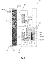
- FIG. 3 is a schematic representation of another embodiment of a heating system 10 with a module 44 for integration of the external heat generator 16 is shown.
- the integrated Heat exchanger 56 and tube heat exchanger 58 hydraulically connected to the interior of the hydraulic separator 46 via an opening 60 to the integrated heat exchanger 56, whereby an exchange of heating medium between the hot water heating circuit 54 and the heating circuit 14 is made possible.
- the flow of the external heat generator must not be connected directly to the interior of the hydraulic switch 46 so that heated heating water can flow from the external heat generator in the hydraulic switch.
- the opening 60 in the integrated heat exchanger 56 it is sufficient to connect the flow 52 of the external heat generator 16 only with the integrated heat exchanger 56 of the hydraulic switch 46, whereby material costs are saved in the installation of the heating system 10.
- the medium of the hot water heating circuit flows either through the tube heat exchanger 58 to the second heat exchanger 26 in the hot water tank 62, or buffer memory 20, or through the opening 60, or the hole 61, in the interior of the hydraulic switch 46 to the heating circuit.
- the invention also relates to a method for operating a heating system 10.
- the method is characterized in that a temperature is detected at the at least one hydraulic switch 46.
- the temperature is detected by means of the temperature sensor 42. This allows a temperature measurement directly on the hydraulic switch 46, which in turn can be determined whether a heat request to the heating system 10 is made.
- a temperature change is detected at the hydraulic switch 46, whereby the temperature behavior of the hydraulic switch 46 can be observed particularly effective.
- a medium of the hot water heating circuit 54 is passed through the hydraulic switch 46 and through the integrated heat exchanger 56, whereby an efficient heat exchange between the external heat generator 16, and the medium of the hot water heating circuit 54 coming from the external heat generator 16, and the heating water of the heating circuit 14 in the interior of the hydraulic switch 46 is made possible.
- an operation corresponding to a heating of service water is or remains set when a temperature increase is detected at the at least one hydraulic switch 46, i. if no heat request is made to the heating circuit 14, and the return temperature of the heating circuit 14 in terms of amount is greater than the storage temperature of the hot water tank 62 and the buffer memory 20th
- the operation corresponding to a heating of the service water is adjusted by means of the three-way valve 48, by allowing only the reflux of the medium from the hot water heating circuit 54.
- the operation corresponding to a warming of service water is or is now stopped, if a temperature increase is detected at the at least one hydraulic switch 46, or is thus stopped, i. If no heat request is made to the heating circuit 14, and the return temperature of the heating circuit 14 is greater in magnitude than the storage temperature of the hot water tank 62 and the buffer memory 20, the switching of the three-way valve 48 is particularly efficient and robust, as a frequent Switching the three-way valve 48 is avoided.
- the operation corresponding to a heating of service water is or remains set when the temperature value at the hydraulic switch 64 amount is greater than a limit of 42 ° C, thereby ensuring that the hydraulic switch 56 does not overheat.
- an operation corresponding to a heating of heating water is or remains set if a temperature decrease at the hydraulic separator 56 is detected and the return temperature of the heating circuit 14 is smaller than at least the storage temperature of the service water storage tank 62 or of the storage tank 20.
- the operation corresponding to a heating of heating water of the heating circuit 14 is likewise set by means of the three-way valve 48, in that only the reflux of the heating water from the heating circuit 14 is allowed.
- the operation corresponding to a heating of heating water is set or maintained when the temperature value is less than or equal to the limit value of 42 ° C, thereby ensuring that the hydraulic switch 56 does not cool down too much.
- control and regulation such as the three-way valves 23, 38, 48 and the compressor 40, 49, the heating system 10, as well as the evaluation of parameters, such as the temperature measurement by means of the temperature sensor 42 to the hydraulic switch, are by a Control unit, which is not shown for an improved representation made.
- a Control unit which is not shown for an improved representation made.
- the control unit could also be integrated in the module 44.
Landscapes
- Engineering & Computer Science (AREA)
- Physics & Mathematics (AREA)
- Thermal Sciences (AREA)
- Chemical & Material Sciences (AREA)
- Combustion & Propulsion (AREA)
- Mechanical Engineering (AREA)
- General Engineering & Computer Science (AREA)
- Water Supply & Treatment (AREA)
- Heat-Pump Type And Storage Water Heaters (AREA)
- Steam Or Hot-Water Central Heating Systems (AREA)
Applications Claiming Priority (1)
| Application Number | Priority Date | Filing Date | Title |
|---|---|---|---|
| DE102015205646 | 2015-03-27 |
Publications (2)
| Publication Number | Publication Date |
|---|---|
| EP3073200A1 true EP3073200A1 (fr) | 2016-09-28 |
| EP3073200B1 EP3073200B1 (fr) | 2018-03-28 |
Family
ID=55640616
Family Applications (1)
| Application Number | Title | Priority Date | Filing Date |
|---|---|---|---|
| EP16162646.0A Active EP3073200B1 (fr) | 2015-03-27 | 2016-03-29 | Aiguillage hydraulique chauffe destine a l'integration de chaleur externe |
Country Status (2)
| Country | Link |
|---|---|
| EP (1) | EP3073200B1 (fr) |
| DE (1) | DE102016205114A1 (fr) |
Cited By (2)
| Publication number | Priority date | Publication date | Assignee | Title |
|---|---|---|---|---|
| EP3315867A1 (fr) * | 2016-10-26 | 2018-05-02 | Suncue Company Ltd. | Appareil d'échange de chaleur à commutation multitube |
| EP4160096A1 (fr) * | 2021-10-04 | 2023-04-05 | Robert Bosch GmbH | Système de chauffage hybride pour fournir de l'eau sanitaire et de la chaleur de chauffage |
Families Citing this family (2)
| Publication number | Priority date | Publication date | Assignee | Title |
|---|---|---|---|---|
| DE102021125574B4 (de) | 2021-10-01 | 2023-10-05 | Viessmann Climate Solutions Se | Verfahren zum betreiben eines heizungssystems mit brennstoffzelle und heizungssystem mit brennstoffzelle |
| DE102024121152A1 (de) | 2024-07-25 | 2026-01-29 | Viessmann Holding International GmbH | Heizsystem und Verfahren zum Steuern und/oder Regeln eines Heizsystems |
Citations (4)
| Publication number | Priority date | Publication date | Assignee | Title |
|---|---|---|---|---|
| EP1398591A2 (fr) * | 2002-07-18 | 2004-03-17 | Vaillant GmbH | Accumulateur stratifié |
| DE10340891A1 (de) | 2002-09-06 | 2004-03-18 | Vaillant Gmbh | Heizungsanlage |
| DE202006019415U1 (de) * | 2006-12-22 | 2007-04-05 | Watts Industries Deutschland Gmbh | Vorrichtung zum Speisen von Hoch- und Niedertemperaturverbrauchskreisen |
| DE102009051782A1 (de) * | 2009-02-08 | 2010-08-12 | Schmalhorst, Hagen | Regelung einer hydraulischen Verteilerweiche zur Energieverteilung in Heizungs- Brauchwasseranlagen mit Pufferspeichern |
-
2016
- 2016-03-29 DE DE102016205114.8A patent/DE102016205114A1/de not_active Withdrawn
- 2016-03-29 EP EP16162646.0A patent/EP3073200B1/fr active Active
Patent Citations (4)
| Publication number | Priority date | Publication date | Assignee | Title |
|---|---|---|---|---|
| EP1398591A2 (fr) * | 2002-07-18 | 2004-03-17 | Vaillant GmbH | Accumulateur stratifié |
| DE10340891A1 (de) | 2002-09-06 | 2004-03-18 | Vaillant Gmbh | Heizungsanlage |
| DE202006019415U1 (de) * | 2006-12-22 | 2007-04-05 | Watts Industries Deutschland Gmbh | Vorrichtung zum Speisen von Hoch- und Niedertemperaturverbrauchskreisen |
| DE102009051782A1 (de) * | 2009-02-08 | 2010-08-12 | Schmalhorst, Hagen | Regelung einer hydraulischen Verteilerweiche zur Energieverteilung in Heizungs- Brauchwasseranlagen mit Pufferspeichern |
Cited By (2)
| Publication number | Priority date | Publication date | Assignee | Title |
|---|---|---|---|---|
| EP3315867A1 (fr) * | 2016-10-26 | 2018-05-02 | Suncue Company Ltd. | Appareil d'échange de chaleur à commutation multitube |
| EP4160096A1 (fr) * | 2021-10-04 | 2023-04-05 | Robert Bosch GmbH | Système de chauffage hybride pour fournir de l'eau sanitaire et de la chaleur de chauffage |
Also Published As
| Publication number | Publication date |
|---|---|
| DE102016205114A1 (de) | 2016-09-29 |
| EP3073200B1 (fr) | 2018-03-28 |
Similar Documents
| Publication | Publication Date | Title |
|---|---|---|
| EP3073200B1 (fr) | Aiguillage hydraulique chauffe destine a l'integration de chaleur externe | |
| EP2613097B2 (fr) | Appareil de chauffage | |
| DE102009004319A1 (de) | Verfahren, Computerprogramm und Regelgerät für einen temperaturbasierten hydraulischen Abgleich | |
| DE112011105266T5 (de) | Fluidsteuersystem | |
| DE102014225693A1 (de) | Heizsystem mit Warmwasserbereitstellung | |
| DE102014202738B4 (de) | Verfahren zum automatisierten hydraulischen Abgleich einer Heizungsanlage | |
| EP1939539B1 (fr) | Dispositif destiné à alimenter des circuits haute et basse consommation d'énergie | |
| DE2524010B2 (de) | Steuerung für eine in Abhängigkeit von der Außentemperatur einstellbare Heizungsanlage | |
| DE202007008024U1 (de) | Mischeinrichtung zur Einstellung der Warmwassertemperatur | |
| DE1299393B (de) | Warmwassererzeuger, insbesondere Heizwassererzeuger | |
| DE10244256B4 (de) | Heizanlage und/oder Kühlanlage mit mindestens einer Wärmequelle | |
| DE102011106022A1 (de) | Warmwassererzeugungs-, Speicher- und Abgabevorrichtung | |
| DE19802362C2 (de) | Verfahren und Einrichtung zur Reduzierung der Wartezeit für das Zapfen von warmem Brauchwasser | |
| EP3023709B1 (fr) | Procede de chauffage d'un fluide dans un reservoir dans une installation de chauffage et installation de chauffage associee | |
| DE102013102479B4 (de) | Brennstoffzellenvorrichtung | |
| EP4191159B1 (fr) | Appareil de chauffage, procédé de fonctionnement d'un appareil de chauffage | |
| DE102009038738A1 (de) | Heizungsanlage | |
| DE10340891A1 (de) | Heizungsanlage | |
| AT412670B (de) | Heizungsanlage | |
| DE102022127744B4 (de) | Zentralheizungssystem und Verfahren zum Betrieb und/oder zur Steuerung und/oder zur Regelung eines Zentralheizungssystems | |
| AT523320A1 (fr) | ||
| EP2863135A1 (fr) | Optimisation de température de consigne pour une partie en attente dans des installations de chauffage, en particulier pour le chauffage d'eau potable | |
| EP3835667B1 (fr) | Procédé de commande d'une installation de chauffage et appareil de commande associé | |
| EP2339247A2 (fr) | Procédé de chauffage d'eau non potable | |
| EP1691138A2 (fr) | Chaudière mixte et procédé pour son opération |
Legal Events
| Date | Code | Title | Description |
|---|---|---|---|
| PUAI | Public reference made under article 153(3) epc to a published international application that has entered the european phase |
Free format text: ORIGINAL CODE: 0009012 |
|
| AK | Designated contracting states |
Kind code of ref document: A1 Designated state(s): AL AT BE BG CH CY CZ DE DK EE ES FI FR GB GR HR HU IE IS IT LI LT LU LV MC MK MT NL NO PL PT RO RS SE SI SK SM TR |
|
| AX | Request for extension of the european patent |
Extension state: BA ME |
|
| 17P | Request for examination filed |
Effective date: 20170328 |
|
| RBV | Designated contracting states (corrected) |
Designated state(s): AL AT BE BG CH CY CZ DE DK EE ES FI FR GB GR HR HU IE IS IT LI LT LU LV MC MK MT NL NO PL PT RO RS SE SI SK SM TR |
|
| GRAP | Despatch of communication of intention to grant a patent |
Free format text: ORIGINAL CODE: EPIDOSNIGR1 |
|
| RIC1 | Information provided on ipc code assigned before grant |
Ipc: F24D 3/08 20060101AFI20170921BHEP Ipc: F24D 19/10 20060101ALI20170921BHEP Ipc: F24D 3/10 20060101ALI20170921BHEP |
|
| INTG | Intention to grant announced |
Effective date: 20171020 |
|
| GRAS | Grant fee paid |
Free format text: ORIGINAL CODE: EPIDOSNIGR3 |
|
| GRAA | (expected) grant |
Free format text: ORIGINAL CODE: 0009210 |
|
| AK | Designated contracting states |
Kind code of ref document: B1 Designated state(s): AL AT BE BG CH CY CZ DE DK EE ES FI FR GB GR HR HU IE IS IT LI LT LU LV MC MK MT NL NO PL PT RO RS SE SI SK SM TR |
|
| REG | Reference to a national code |
Ref country code: GB Ref legal event code: FG4D Free format text: NOT ENGLISH |
|
| REG | Reference to a national code |
Ref country code: CH Ref legal event code: EP |
|
| REG | Reference to a national code |
Ref country code: AT Ref legal event code: REF Ref document number: 983792 Country of ref document: AT Kind code of ref document: T Effective date: 20180415 |
|
| REG | Reference to a national code |
Ref country code: IE Ref legal event code: FG4D Free format text: LANGUAGE OF EP DOCUMENT: GERMAN |
|
| REG | Reference to a national code |
Ref country code: DE Ref legal event code: R096 Ref document number: 502016000772 Country of ref document: DE |
|
| REG | Reference to a national code |
Ref country code: FR Ref legal event code: PLFP Year of fee payment: 3 |
|
| PG25 | Lapsed in a contracting state [announced via postgrant information from national office to epo] |
Ref country code: NO Free format text: LAPSE BECAUSE OF FAILURE TO SUBMIT A TRANSLATION OF THE DESCRIPTION OR TO PAY THE FEE WITHIN THE PRESCRIBED TIME-LIMIT Effective date: 20180628 Ref country code: HR Free format text: LAPSE BECAUSE OF FAILURE TO SUBMIT A TRANSLATION OF THE DESCRIPTION OR TO PAY THE FEE WITHIN THE PRESCRIBED TIME-LIMIT Effective date: 20180328 Ref country code: LT Free format text: LAPSE BECAUSE OF FAILURE TO SUBMIT A TRANSLATION OF THE DESCRIPTION OR TO PAY THE FEE WITHIN THE PRESCRIBED TIME-LIMIT Effective date: 20180328 Ref country code: FI Free format text: LAPSE BECAUSE OF FAILURE TO SUBMIT A TRANSLATION OF THE DESCRIPTION OR TO PAY THE FEE WITHIN THE PRESCRIBED TIME-LIMIT Effective date: 20180328 |
|
| REG | Reference to a national code |
Ref country code: NL Ref legal event code: MP Effective date: 20180328 |
|
| REG | Reference to a national code |
Ref country code: LT Ref legal event code: MG4D |
|
| PG25 | Lapsed in a contracting state [announced via postgrant information from national office to epo] |
Ref country code: RS Free format text: LAPSE BECAUSE OF FAILURE TO SUBMIT A TRANSLATION OF THE DESCRIPTION OR TO PAY THE FEE WITHIN THE PRESCRIBED TIME-LIMIT Effective date: 20180328 Ref country code: SE Free format text: LAPSE BECAUSE OF FAILURE TO SUBMIT A TRANSLATION OF THE DESCRIPTION OR TO PAY THE FEE WITHIN THE PRESCRIBED TIME-LIMIT Effective date: 20180328 Ref country code: LV Free format text: LAPSE BECAUSE OF FAILURE TO SUBMIT A TRANSLATION OF THE DESCRIPTION OR TO PAY THE FEE WITHIN THE PRESCRIBED TIME-LIMIT Effective date: 20180328 Ref country code: GR Free format text: LAPSE BECAUSE OF FAILURE TO SUBMIT A TRANSLATION OF THE DESCRIPTION OR TO PAY THE FEE WITHIN THE PRESCRIBED TIME-LIMIT Effective date: 20180629 Ref country code: BG Free format text: LAPSE BECAUSE OF FAILURE TO SUBMIT A TRANSLATION OF THE DESCRIPTION OR TO PAY THE FEE WITHIN THE PRESCRIBED TIME-LIMIT Effective date: 20180628 |
|
| PG25 | Lapsed in a contracting state [announced via postgrant information from national office to epo] |
Ref country code: MT Free format text: LAPSE BECAUSE OF FAILURE TO SUBMIT A TRANSLATION OF THE DESCRIPTION OR TO PAY THE FEE WITHIN THE PRESCRIBED TIME-LIMIT Effective date: 20180328 |
|
| PG25 | Lapsed in a contracting state [announced via postgrant information from national office to epo] |
Ref country code: AL Free format text: LAPSE BECAUSE OF FAILURE TO SUBMIT A TRANSLATION OF THE DESCRIPTION OR TO PAY THE FEE WITHIN THE PRESCRIBED TIME-LIMIT Effective date: 20180328 Ref country code: ES Free format text: LAPSE BECAUSE OF FAILURE TO SUBMIT A TRANSLATION OF THE DESCRIPTION OR TO PAY THE FEE WITHIN THE PRESCRIBED TIME-LIMIT Effective date: 20180328 Ref country code: PL Free format text: LAPSE BECAUSE OF FAILURE TO SUBMIT A TRANSLATION OF THE DESCRIPTION OR TO PAY THE FEE WITHIN THE PRESCRIBED TIME-LIMIT Effective date: 20180328 Ref country code: NL Free format text: LAPSE BECAUSE OF FAILURE TO SUBMIT A TRANSLATION OF THE DESCRIPTION OR TO PAY THE FEE WITHIN THE PRESCRIBED TIME-LIMIT Effective date: 20180328 Ref country code: RO Free format text: LAPSE BECAUSE OF FAILURE TO SUBMIT A TRANSLATION OF THE DESCRIPTION OR TO PAY THE FEE WITHIN THE PRESCRIBED TIME-LIMIT Effective date: 20180328 Ref country code: IT Free format text: LAPSE BECAUSE OF FAILURE TO SUBMIT A TRANSLATION OF THE DESCRIPTION OR TO PAY THE FEE WITHIN THE PRESCRIBED TIME-LIMIT Effective date: 20180328 Ref country code: EE Free format text: LAPSE BECAUSE OF FAILURE TO SUBMIT A TRANSLATION OF THE DESCRIPTION OR TO PAY THE FEE WITHIN THE PRESCRIBED TIME-LIMIT Effective date: 20180328 |
|
| PG25 | Lapsed in a contracting state [announced via postgrant information from national office to epo] |
Ref country code: SK Free format text: LAPSE BECAUSE OF FAILURE TO SUBMIT A TRANSLATION OF THE DESCRIPTION OR TO PAY THE FEE WITHIN THE PRESCRIBED TIME-LIMIT Effective date: 20180328 Ref country code: CZ Free format text: LAPSE BECAUSE OF FAILURE TO SUBMIT A TRANSLATION OF THE DESCRIPTION OR TO PAY THE FEE WITHIN THE PRESCRIBED TIME-LIMIT Effective date: 20180328 Ref country code: SM Free format text: LAPSE BECAUSE OF FAILURE TO SUBMIT A TRANSLATION OF THE DESCRIPTION OR TO PAY THE FEE WITHIN THE PRESCRIBED TIME-LIMIT Effective date: 20180328 |
|
| REG | Reference to a national code |
Ref country code: BE Ref legal event code: MM Effective date: 20180331 |
|
| REG | Reference to a national code |
Ref country code: IE Ref legal event code: MM4A |
|
| PG25 | Lapsed in a contracting state [announced via postgrant information from national office to epo] |
Ref country code: LU Free format text: LAPSE BECAUSE OF NON-PAYMENT OF DUE FEES Effective date: 20180329 Ref country code: PT Free format text: LAPSE BECAUSE OF FAILURE TO SUBMIT A TRANSLATION OF THE DESCRIPTION OR TO PAY THE FEE WITHIN THE PRESCRIBED TIME-LIMIT Effective date: 20180730 |
|
| REG | Reference to a national code |
Ref country code: DE Ref legal event code: R097 Ref document number: 502016000772 Country of ref document: DE |
|
| PG25 | Lapsed in a contracting state [announced via postgrant information from national office to epo] |
Ref country code: IE Free format text: LAPSE BECAUSE OF NON-PAYMENT OF DUE FEES Effective date: 20180329 Ref country code: MC Free format text: LAPSE BECAUSE OF FAILURE TO SUBMIT A TRANSLATION OF THE DESCRIPTION OR TO PAY THE FEE WITHIN THE PRESCRIBED TIME-LIMIT Effective date: 20180328 Ref country code: DK Free format text: LAPSE BECAUSE OF FAILURE TO SUBMIT A TRANSLATION OF THE DESCRIPTION OR TO PAY THE FEE WITHIN THE PRESCRIBED TIME-LIMIT Effective date: 20180328 |
|
| PLBE | No opposition filed within time limit |
Free format text: ORIGINAL CODE: 0009261 |
|
| STAA | Information on the status of an ep patent application or granted ep patent |
Free format text: STATUS: NO OPPOSITION FILED WITHIN TIME LIMIT |
|
| PG25 | Lapsed in a contracting state [announced via postgrant information from national office to epo] |
Ref country code: BE Free format text: LAPSE BECAUSE OF NON-PAYMENT OF DUE FEES Effective date: 20180331 |
|
| 26N | No opposition filed |
Effective date: 20190103 |
|
| PG25 | Lapsed in a contracting state [announced via postgrant information from national office to epo] |
Ref country code: SI Free format text: LAPSE BECAUSE OF FAILURE TO SUBMIT A TRANSLATION OF THE DESCRIPTION OR TO PAY THE FEE WITHIN THE PRESCRIBED TIME-LIMIT Effective date: 20180328 |
|
| REG | Reference to a national code |
Ref country code: CH Ref legal event code: PL |
|
| PG25 | Lapsed in a contracting state [announced via postgrant information from national office to epo] |
Ref country code: CH Free format text: LAPSE BECAUSE OF NON-PAYMENT OF DUE FEES Effective date: 20190331 Ref country code: LI Free format text: LAPSE BECAUSE OF NON-PAYMENT OF DUE FEES Effective date: 20190331 |
|
| PG25 | Lapsed in a contracting state [announced via postgrant information from national office to epo] |
Ref country code: TR Free format text: LAPSE BECAUSE OF FAILURE TO SUBMIT A TRANSLATION OF THE DESCRIPTION OR TO PAY THE FEE WITHIN THE PRESCRIBED TIME-LIMIT Effective date: 20180328 |
|
| PG25 | Lapsed in a contracting state [announced via postgrant information from national office to epo] |
Ref country code: CY Free format text: LAPSE BECAUSE OF FAILURE TO SUBMIT A TRANSLATION OF THE DESCRIPTION OR TO PAY THE FEE WITHIN THE PRESCRIBED TIME-LIMIT Effective date: 20180328 Ref country code: MK Free format text: LAPSE BECAUSE OF NON-PAYMENT OF DUE FEES Effective date: 20180328 Ref country code: HU Free format text: LAPSE BECAUSE OF FAILURE TO SUBMIT A TRANSLATION OF THE DESCRIPTION OR TO PAY THE FEE WITHIN THE PRESCRIBED TIME-LIMIT; INVALID AB INITIO Effective date: 20160329 |
|
| PG25 | Lapsed in a contracting state [announced via postgrant information from national office to epo] |
Ref country code: IS Free format text: LAPSE BECAUSE OF FAILURE TO SUBMIT A TRANSLATION OF THE DESCRIPTION OR TO PAY THE FEE WITHIN THE PRESCRIBED TIME-LIMIT Effective date: 20180728 |
|
| REG | Reference to a national code |
Ref country code: AT Ref legal event code: MM01 Ref document number: 983792 Country of ref document: AT Kind code of ref document: T Effective date: 20210329 |
|
| PG25 | Lapsed in a contracting state [announced via postgrant information from national office to epo] |
Ref country code: AT Free format text: LAPSE BECAUSE OF NON-PAYMENT OF DUE FEES Effective date: 20210329 |
|
| PGFP | Annual fee paid to national office [announced via postgrant information from national office to epo] |
Ref country code: DE Payment date: 20250522 Year of fee payment: 10 |
|
| PGFP | Annual fee paid to national office [announced via postgrant information from national office to epo] |
Ref country code: GB Payment date: 20260324 Year of fee payment: 11 |
|
| PGFP | Annual fee paid to national office [announced via postgrant information from national office to epo] |
Ref country code: FR Payment date: 20260324 Year of fee payment: 11 |