EP3073245B1 - Système et procédé permettant de déterminer une tolérance autorisée aux dommages directes - Google Patents
Système et procédé permettant de déterminer une tolérance autorisée aux dommages directes Download PDFInfo
- Publication number
- EP3073245B1 EP3073245B1 EP16162437.4A EP16162437A EP3073245B1 EP 3073245 B1 EP3073245 B1 EP 3073245B1 EP 16162437 A EP16162437 A EP 16162437A EP 3073245 B1 EP3073245 B1 EP 3073245B1
- Authority
- EP
- European Patent Office
- Prior art keywords
- load
- crack
- threshold
- notch
- stress
- Prior art date
- Legal status (The legal status is an assumption and is not a legal conclusion. Google has not performed a legal analysis and makes no representation as to the accuracy of the status listed.)
- Not-in-force
Links
Images





Classifications
-
- G—PHYSICS
- G01—MEASURING; TESTING
- G01N—INVESTIGATING OR ANALYSING MATERIALS BY DETERMINING THEIR CHEMICAL OR PHYSICAL PROPERTIES
- G01N3/00—Investigating strength properties of solid materials by application of mechanical stress
- G01N3/08—Investigating strength properties of solid materials by application of mechanical stress by applying steady tensile or compressive forces
-
- G—PHYSICS
- G01—MEASURING; TESTING
- G01N—INVESTIGATING OR ANALYSING MATERIALS BY DETERMINING THEIR CHEMICAL OR PHYSICAL PROPERTIES
- G01N3/00—Investigating strength properties of solid materials by application of mechanical stress
- G01N3/32—Investigating strength properties of solid materials by application of mechanical stress by applying repeated or pulsating forces
-
- G—PHYSICS
- G01—MEASURING; TESTING
- G01N—INVESTIGATING OR ANALYSING MATERIALS BY DETERMINING THEIR CHEMICAL OR PHYSICAL PROPERTIES
- G01N2203/00—Investigating strength properties of solid materials by application of mechanical stress
- G01N2203/0058—Kind of property studied
- G01N2203/006—Crack, flaws, fracture or rupture
- G01N2203/0062—Crack or flaws
- G01N2203/0066—Propagation of crack
Definitions
- the embodiments of the present disclosure relate to determining damage tolerance allowables for a structure, such as an aircraft structure.
- Conventional method of determining damage tolerance allowables for aircraft structure can include multiple steps of approximations and derivations that have conservatism and variability, which can result in the designing of aircraft structures with too much conservatism, thus being heavier than actually necessary.
- a conventional method of calculating damage tolerance allowables is outlined in ASTM E647.
- US4090401 discloses a method of endurance testing in which in a the first test loading cycle an overload is intentionally applied to the test member, but in a second and subsequent test loading cycles a load smaller than that applied in the first cycle is applied to the test member.
- K A ZAKARIA ET AL "FRACTOGRAPHY ANALYSIS OF AI6061 UNDER FATIGUE SPECTRUM LOADINGS", ENGINEERING E-TRANSACTION, (20120629), vol. 7, no. 29, pages 28 - 33 discloses observations of crack propagations of A16061 under fatigue spectrum loading, identifying fracture behavior under particular load sequences including high to low and low to high spectrum loadings.
- Damage tolerance allowables are essential for the damage tolerance design of rotorcraft structures, such as dynamic parts.
- the combination of those conditions flow down to the structures and translate into a certain stress level that depends upon the material composition of the parts and the detail design of the parts.
- a comparison of that stress level of the part to the damage tolerance allowables determines whether the part can satisfy the damage tolerance requirements with the particular design. If the stress level exceeds the damage tolerance allowables, the part requires re-design to reduce the stress level of the part, which typically causes an increase in the weight of the part or a decrease in the overall load and usage capability of the aircraft.
- the stress level of the part would have to be designed to meet the overly conservative damage tolerance criteria, which would cause the size (and weight) of the part to increase to meet the given usage and load requirements of the aircraft. Alternatively, the usage and load capabilities of the aircraft would need to be lowered to maintain any weight requirements.
- the present disclosure includes methods and systems of generating no-growth damage tolerance allowables for structures, which allow for higher stress level in the damage tolerant designed part with less weight while meeting the usage and load requirements of the aircraft.
- Certain embodiments include methods and systems of directly obtaining no-growth damage tolerance allowables for aircraft structure, the allowables being approximately 15%-30% higher than allowables produced by the conventional ASTM E647 method. Moreover, a 15%-30% higher allowable can equate to an approximately 15%-30% weight savings of the aircraft structure.
- certain embodiments of the methods and systems of directly obtaining no-growth damage tolerance allowables for aircraft structure may prevent the necessity of full scale aircraft structure testing that may otherwise be required for certification.
- the method of the present application is a coupon specimen testing method that generates threshold stress data for fatigue crack initiation in a metallic material.
- threshold can be the fatigue stress state ⁇ mean stress, oscillatory stress ⁇ , below which a flaw or a crack in a metallic material will not grow.
- threshold stress may also be called “no-growth threshold.”
- the test method generates threshold stress data for crack initiation.
- the test specimen can be a square-bar coupon, cyclically loaded along the axis. Each coupon specimen contains a notch at a corner of the center-plane of the specimen to simulate a flaw.
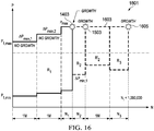
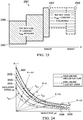
- a graphic 2301 illustrates how the method derives the threshold stress.
- the testing continues and turns into determination of threshold stress for a crack, which becomes evident by a crack growth occurrence 2309.
- the testing maintains the last maximum load for the test with the flaw to avoid overload effect, but changes the minimum load.
- the same process as testing with flaw is used and may need to be repeated until the threshold stress is achieved for the crack.
- the tests can be performed with various stress ratios R for the coupons of same notch size a 0 , which together generate a threshold stress curves ⁇ s mean , s osc ⁇ for notch length a 0,1 .
- the threshold stress curves can be achieved for various flaw sizes, shown as solid lines 2401, 2403, 2405 in Figure 24 .
- the data obtained for various crack lengths can also form the threshold stress curves for no-growth of crack(s), shown as dotted lines 2402, 2404, 2406 in Figure 24 .
- exemplary threshold stress data generated via the test method is illustrated, wherein ( a 0,1 ⁇ a 0,2 ⁇ a 0,3 ).
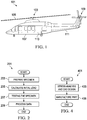
- Rotorcraft 101 can have a rotor system 103 with a plurality of rotor blades 105. The pitch of each rotor blade 105 can be manipulated in order to selectively control direction, thrust, and lift of rotorcraft 101.
- Rotorcraft 101 can further include a fuselage 107, anti-torque system 109, and an empennage 111.
- the structure of rotorcraft 101 can include a variety of airframe structures, such as bulkheads, ribs, longerons, stringers, keels, skins, spars, to name a few examples.
- a bulkhead 113 is labeled for illustrative purposes.
- rotorcraft 101 is merely illustrated as one of many different types of aircraft whose structure can be analyzed and designed using the methods and systems of the present disclosure.
- other aircraft can include, fixed wing aircraft, hybrid aircraft, unmanned aircraft, tiltrotor aircraft, to name a few examples.
- method 201 is a test method for determining no-growth threshold stress for a flaw or a crack in a metallic component.
- Applicable metals can include aluminum, titanium, and steel, to name a few examples.
- the conventional ASTM E647 method derives crack growth threshold ( ⁇ K TH ) from the derived crack growth rate curve (da/dN vs. ⁇ K) that is based on crack growth testing a-N data, where K is stress intensity factor (SIF).
- ⁇ K TH is derived, it is further converted into no-growth threshold fatigue stress.
- the direct test method 201 can generate a fatigue stress data in which a flaw or a crack will not grow. In this way, the no-growth damage tolerance allowables can be determined based on the directly obtained fatigue test stress data.
- Method 201 can include a step 203 of preparing a specimen, a step 205 of calculating an initial load, a step 207 of testing the specimen, and a step 209 of processing data. Each of these steps are described in further detail herein.
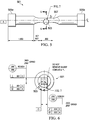
- specimen 501 which can also be referred to herein as "Ks Bar", is illustrated.
- specimen 501 is a bar coupon for an axially loaded fatigue test that has a gauge of square cross-section and a corner notch 503 on the middle plane of the specimen 501.
- the specimen 501 is symmetric about a center-plane.
- Method 201 generates crack initiation data with using one or more specimens 501, each with a corner notch 503 at the center-plane of the specimen 501.
- three notch sizes can be utilized.
- Example nominal notch sizes for general metal-forming materials are 0.005-inch, 0.010-inch, and 0.015-inch, measured on each side of the corner of the specimen 501.
- Example nominal notch sizes for casting materials are 0.015-inch, 0.025-inch, and 0.050-inch, also measured on each side of the specimen 501.
- at least two specimens 501 can be used for each stress ratio tests.
- Table 1 lists an example specimen matrix for the requirements of test specimens, i.e., thirty-six coupons.
- four un-notched spare specimens 501 can be used to mitigate unexpected events, resulting in a total of forty coupons that can be used in the example test program. It should be appreciated that the exact quantity of specimens 501 used in method 501 is implementation specific; furthermore, the quantity of specimens 501 described herein are for exemplary purposes and are not intended to be restrictive. Table 1.
- the specimen 501 is machined from the material direction so that the corner notch 503 of the specimen 501 is of the same material orientation as in the structural part.
- the axial direction of the specimen 501 can align with the thickness direction if it is made from a thick plate, or can align with the radius direction if it is made from a round bar. With this alignment, the corner notch 503 of a specimen 501 is in the S-T or R-C orientation. There may not be a specific requirement on alignment of the specimen 501 with respect to the sand casting material since the grain direction is not significant in such a case.
- the length of the specimen 501 can be any implementation specific length; however, one example length is approximately four inches. Another example length is five inches.
- the head buttons 505a and 505b of the specimen 501 are designed for the axial load application, for which the perpendicularity of the shoulders to the axis of the specimen 501 is desired during the test.
- a gauge section 507 is of square cross-section.
- the center cross-section of the gauge section 507 is the mid-plane (also symmetric plane) of the specimen 507, on which a notch 503 is induced at a corner, as shown at least in Figures 7 and 8 .
- the width W of the corner notch 503 is 0.003-inch. It is desired that the bottom of the corner notch 503 (also called notch front) have a curved portion R1 as shown in Figures 7 and 8 .
- the material of the specimen 501 should be the same as the material as the structural part of which the damage tolerance allowables are being determined.
- the material of the specimen 501 should not only be of the same material, but also have the same material conditions, such as ultimate tensile strength (UTS), heat-treatment, hardening condition, and material form, as the structural part of which the damage tolerance allowables are being determined.
- UTS ultimate tensile strength
- heat-treatment heat-treatment
- hardening condition hardening condition
- material form as the structural part of which the damage tolerance allowables are being determined.
- notch 503 is generated using an electrical discharge machining (EDM) method; however, it should be appreciated that other methods of creating notch 503 may be used, such as sawing, broaching, or milling, for example, as long as notch can be created with a curved portion R1.
- EDM electrical discharge machining
- notch 503 is metallurgically depicted.
- a post-notching chemical treatment can be desirable to modify the EDM corner notch of the specimen 501.
- One purpose of the etching process is to remove re-melt material layer of high hardness along a notch surface 505 of the notch 503.
- the re-melt material layer can be caused by high temperature of electric discharge during the notching process.
- Another important purpose of the post-notching treatment is to weaken the grain bonds along the notch surface 505 of notch 503 to make the evaluation more conservative.
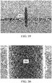
- Figure 19 shows an example of a corner notch 503 produced with an EMD process.
- Figure 20 is a close-up view of a front of the notch 503 before chemical modification.
- Figure 21 is a close-up view of a front of the notch 503 after chemical modification. A comparison between Figures 20 and 21 reveals that the re-melt layer has been disintegrated and separated from a root notch 509 of notch 503 after the treatment. This results in a desired notch severity (worst notch) for the test.
- Figure 22 illustrates the notch 503 in a specimen 501 that has been sectioned at the crack plane after testing.
- a sectioning of specimens 501 can be performed to verify notch measurements and crack measurements using a scanning electron microscope (SEM) measurement, for example.
- Creation and etching of the notch 505 results in a notch root 509.
- a first crack 507 is created, which exists between notch root 509 and a first crack front 511.
- the test is temporarily halted upon detection of the first crack 511.
- the test can be resumed until a second crack 506 is created between first crack front 511 and a second crack front 513.
- an exemplary specimen ID 901 can be utilized to mark each specimen 901 to keep track of critical information and insure accurate test data.
- the specimen ID 901 can include information such as: Test Request (TR) number, the location that specimen blank is cut out from the stock material, the notch size, and the stress ratio at which the coupon will be tested, as illustrated in Figure 9 .
- TR Test Request
- method 201 further includes a step 205 of calculating an initial load.
- the step 207 of testing the specimen(s) 501 is an iterative process that starts with an initial load to converge the load to the point at which the flaw starts to grow.
- a reference da/dN vs. ⁇ K curve is preferred to narrow the range for the initial load determination.
- the reference information can be an existing ⁇ K TH data or a plot of da/dN vs. ⁇ K curves referred for the material to be tested or for the materials that have characteristics similar to that to be tested. These characteristics include the chemical elements of the material, ultimate tensile strength (UTS), material form, and material treatments.
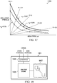
- Figure 10 is an example of a da/dN vs. ⁇ K curve 1001 for Ti-6AI-4V.
- Step 205 can further include using a stress intensity factor (SIF) to calculate the initial load.
- SIF stress intensity factor
- SIF equations for a corner notch (crack) of a square bar can be used in the initial load calculation.
- a correction factor can be used to account for geometrical effects on SIF.
- Figure 8 depicts geometries and loading application for the test procedure. Table 2 lists the notations of Figure 8 and the associated descriptions. Table 2.
- Method 201 is an iterative process which can include an interval of cycles, such as 1,000,000 cycles for example, for each step of iteration until a flaw (or a crack) starts to grow.
- the test starts with an initial load and iterates with the calculated load increments until the flaw grows.
- Equations 1-8 are the basis to determine initial load from stress intensity factor (SIF) for a corner crack initiation test.
- Equation 1 By re-arranging Equation 1, with the support of Equations 2-8 and Table 3, the remote stress S 0 can be calculated. Multiplying S 0 by area of gauge cross-section, the initial load can be determined.
- method 201 further includes a step 207 of testing the specimen(s) 501.
- Step 207 includes iteratively loading a specimen 501 at stepped loads for an implementation specific number of cycles until a flaw (or a crack) starts to grow in corner notch 503.
- the test process in step 207 starts with an Initial Load (P 0 ) and ends at the Final Load (P C ) at which the flaw (or crack) starts to grow.
- P 0 Initial Load
- P C Final Load
- Each test determines the Final Load, Mean Stress, and Oscillatory Stress for the given flaw size, stress ratio, and limited cycles.
- pretest data can include: 1) gauge section dimensions t and W (measurements), 2) notch dimensions a 0 , c 0 , and b, where b is the width of the notch (measurements), 3) stress ratio R, 4) Initial Load P 1 , 5) final crack length a c and c c , 6) testing frequency, and 7) lab temperature (recorded by the testing lab), and 8) lab humidity (recorded by the testing lab).
- the testing step 207 can further include: installing the specimen 501, tuning for alignment, calibrating the measurement and data acquisition system, setting P max and P min for cyclic load, setting potential drop (PD) using a needle-spring method.
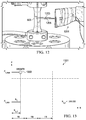
- a specimen 501 is illustrated installed in a test setup.
- a first needle 1203 and a second needled 1205 are pressed against either side of the notch 503.
- a current is passed through the notch 502 between needles 1203 and 1205.
- the detection of crack growth is a result of a change in electrical resistance between needles 1203 and 1205.
- the utilization of needles 1203 and 1205 in a PD system 1201 prevents the need for welding or otherwise attaching sensors that could prove an undesired cracking or annealing of the specimen 501.
- step 207 of method 201 is illustrated in a block diagram format. Step 207 can be broken down between a constant R testing loop 1101 and a constant P max testing loop 1103. Each of the constant R testing loop 1101 and a constant P max testing loop 1103 are discussed further herein.
- the constant R testing loop 1101 can include starting the test with the PD 1201 turned on and cycle count on. If a crack extension is detected via the PD 1201, the test is stopped, as shown in graph 1301 of Figure 13 . In the illustrated graph 1301, a crack extension is detected at occurrence 1303, which is as a point in time short of the first full 1,000,000 cycles. Next the crack dimensions are measured. In one example embodiment, the dimensions of the crack, such as first crack 507, can be measured by an optical microscope on the sides of specimen 501 while the specimen is still attached to the test setup. If crack dimensions exceed the given final crack length a c and c c , the test is completed and the results are reported.
- test proceeds to the next step. If crack dimensions do not reach a c and c c , then the test proceeds to the next step. If a crack extension is not detected, the test continues until 1,000,000 cycles are reached and a testing block is considered completed. An example completed testing block that did not experience crack extension is illustrated as testing block 1405 as shown by graph 1401 in Figure 14 . The next step-load is prepared, the cycle count is reset to zero, and the test restarted. The steps are repeated until a crack extension is detected or until "stop-test", whichever comes first, then the constant R testing loop 1101 ( Figure 11 ) is exited. In the illustrated graph 1401, a crack extension is detected at occurrence 1403, which is as a point in time after two full 1,000,000 cycles, but short completion of the third stepped 1,000,000 cycle testing block.
- the constant P max testing loop 1103 with stepped P min , constant P max , and varying R can include resetting cycle count to zero and resetting loads with an increased P min while keeping the P max the same as that at the constant R loop 1101.
- the test is resumed with cycle count and PD 1201 turned on. If a crack extension is detected at an occurrence 1503 via PD, the test is stopped, as shown in graph 1501 of Figure 15 .
- the extended crack dimension is measured. If the crack dimension exceeds the given final crack length a c and c c , the test is completed. If the crack dimensions do not reach a c and c c , then the test continues to the next step.
- Method 201 can also include a step 209 of processing the data from the test.
- Step 209 is intended to extract the specimen and testing information for each test and determine the validity of the testing result data.
- Valid data for a threshold testing program can be defined as the data at the crack initiation (or extension) ⁇ a / ⁇ N ⁇ 4x10 -9 in/cycle. If this criterion is met at the crack initiation, the load is valid as a threshold for no-growth. If the threshold criterion is not met at the crack initiation, the previous run-out load can be used instead.
- the actual notch dimensions can be measured as 0.012, 0.009, 0.010, 0.012, 0.010, 0.008, 0.011, etc.
- the LEFM adjustment can be made to collapse the non 0.010-in data onto 0.010-in equivalent.
- the data can be adjusted if the crack lengths that are measured during testing are different from the actual crack lengths determined in a post-test measurement.
- Table 1 Example Data Table of Organized Geometrical and Test Results Data Notch Length Specimen# 0'-Notch 1 b1 b2 R N P max (at break) P max (previous) Runout at last run?
- a step 403 can include designing a structure with a computer aided design (CAD) tool which can include defining a preliminary geometry of the structure.
- Step 403 can include performing a stress analysis of the structure, this analysis can include analytically subjecting the structure to loads, calculating the stress, and evaluating the stress with regard to the damage tolerance allowables, the damage tolerance allowables being calculated using method 201 described herein.
- Step 403 can include iteratively changing the geometry of the part until a weight efficient configuration is reached. In one embodiment, the geometry of the structure is iteratively optimized so as to meet the stress allowables without having unnecessary weight.
- a step 405 can include manufacturing the structure to the geometry defined in step 403.
- Computer system 1801 can be configured for performing one or more functions with regard to the operation of system and method further disclosed herein. Further, any processing and analysis can be partly or fully performed by computer system 1801. Computer system 1801 can be partly or fully integrated with other aircraft computer systems.
- the system 1801 can include an input/output (I/O) interface 1803, an analysis engine 1805, and a database 1807. Alternative embodiments can combine or distribute the input/output (I/O) interface 1803, analysis engine 1805, and database 1807, as desired.
- Embodiments of the system 1801 can include one or more computers that include one or more processors and memories configured for performing tasks described herein. This can include, for example, a computer having a central processing unit (CPU) and non-volatile memory that stores software instructions for instructing the CPU to perform at least some of the tasks described herein.
- CPU central processing unit
- This can also include, for example, two or more computers that are in communication via a computer network, where one or more of the computers include a CPU and non-volatile memory, and one or more of the computer's non-volatile memory stores software instructions for instructing any of the CPU(s) to perform any of the tasks described herein.
- the exemplary embodiment is described in terms of a discrete machine, it should be appreciated that this description is non-limiting, and that the present description applies equally to numerous other arrangements involving one or more machines performing tasks distributed in any way among the one or more machines. It should also be appreciated that such machines need not be dedicated to performing tasks described herein, but instead can be multi-purpose machines, for example computer workstations, that are suitable for also performing other tasks.
- the I/O interface 1803 can provide a communication link between external users, systems, and data sources and components of the system 1801.
- the I/O interface 1803 can be configured for allowing one or more users to input information to the system 1801 via any known input device. Examples can include a keyboard, mouse, touch screen, and/or any other desired input device.
- the I/O interface 1803 can be configured for allowing one or more users to receive information output from the system 1801 via any known output device. Examples can include a display monitor, a printer, cockpit display, and/or any other desired output device.
- the I/O interface 1803 can be configured for allowing other systems to communicate with the system 1801.
- the I/O interface 1803 can allow one or more remote computer(s) to access information, input information, and/or remotely instruct the system 1801 to perform one or more of the tasks described herein.
- the I/O interface 1803 can be configured for allowing communication with one or more remote data sources.
- the I/O interface 1803 can allow one or more remote data source(s) to access information, input information, and/or remotely instruct the system 1801 to perform one or more of the tasks described herein.
- the database 1807 provides persistent data storage for system 1801. While the term "database" is primarily used, a memory or other suitable data storage arrangement may provide the functionality of the database 1807. In alternative embodiments, the database 1807 can be integral to or separate from the system 1801 and can operate on one or more computers. The database 1807 preferably provides non-volatile data storage for any information suitable to support the operation of the system and method disclosed herein, including various types of data discussed further herein.
- the analysis engine 1805 can include various combinations of one or more processors, memories, and software components.
Landscapes
- Physics & Mathematics (AREA)
- Health & Medical Sciences (AREA)
- Life Sciences & Earth Sciences (AREA)
- Chemical & Material Sciences (AREA)
- Analytical Chemistry (AREA)
- Biochemistry (AREA)
- General Health & Medical Sciences (AREA)
- General Physics & Mathematics (AREA)
- Immunology (AREA)
- Pathology (AREA)
- Investigating Strength Of Materials By Application Of Mechanical Stress (AREA)
Claims (17)
- Procédé de détermination d'une tolérance admissible aux dommages dans une éprouvette (501), le procédé comprenant :l'application d'une charge cyclique sur une éprouvette (501), l'éprouvette présentant une entaille (503), jusqu'à ce qu'une première fissure (507) émanant de l'entaille (503) soit détectée, la charge cyclique présentant une charge maximale et une charge minimale ; etl'application d'une charge cyclique subséquente sur l'éprouvette (501) jusqu'à ce qu'une extension de la première fissure (507) pour former une seconde fissure (506) émanant de la première fissure (507) soit détectée, la charge cyclique subséquente présentant la même charge maximale mais une charge minimale plus élevée.
- Procédé selon la revendication 1, dans lequel l'éprouvette (501) présente une partie carrée en coupe transversale et l'entaille (503) est située dans un coin de la partie carrée en coupe transversale.
- Procédé selon la revendication 1, comprenant en outre :
la détermination d'une contrainte seuil de défaut sur la base de la charge maximale et de la charge minimale pour laquelle la première fissure (507) commence à émaner de l'entaille (503). - Procédé selon la revendication 1, comprenant en outre :
la détermination d'une contrainte seuil de défaut pour laquelle la seconde fissure (506) croît à partir de la première fissure (507) sur la base de la même charge maximale et de la charge minimale plus élevée. - Procédé selon la revendication 1, comprenant en outre :
l'application d'une charge cyclique initiale sur une éprouvette (501) jusqu'à ce qu'un nombre de cycles atteigne un nombre prédéterminé, la charge cyclique initiale présentant un maximum de charge initiale et un minimum de charge initiale. - Procédé selon la revendication 5, dans lequel la charge maximale et la charge minimale de la charge cyclique forment un rapport de charges, et dans lequel le maximum de charge initiale et le minimum de charge initiale de la charge cyclique initiale forment un rapport de charges initiales.
- Procédé selon la revendication 6, dans lequel(i) la charge maximale est supérieure au maximum de charge initiale ; ou(ii) le rapport de charges initiales est égal au rapport de charge.
- Procédé selon la revendication 1, comprenant en outre :(i) la mesure de la première fissure (507) ; et/ou(ii) la mesure de la seconde fissure (506).
- Procédé selon la revendication 1, comprenant en outre :
la détermination d'une charge oscillatoire de défaut seuil en ajoutant la charge maximale et la charge minimale ensemble et ensuite en divisant par deux. - Procédé selon la revendication 1, comprenant en outre :
la détermination d'une charge oscillatoire de fissure seuil en ajoutant la même charge maximale et la charge minimale plus élevée ensemble et ensuite en divisant par deux. - Procédé selon la revendication 1, comprenant en outre :
la détermination d'une charge moyenne de défaut seuil en soustrayant la charge minimale de la charge maximale et ensuite en divisant par deux. - Procédé selon la revendication 1, comprenant en outre :
la détermination d'une charge moyenne de fissure seuil en ajoutant la même charge maximale et la charge minimale plus élevée ensemble et ensuite en divisant par deux. - Procédé selon la revendication 9, comprenant en outre :
la détermination d'une contrainte seuil en divisant la charge oscillatoire de défaut seuil par une surface plane de l'entaille (503). - Procédé selon la revendication 10, comprenant en outre :
la détermination d'une contrainte seuil en divisant la charge oscillatoire de fissure seuil par une surface plane de l'entaille (503). - Procédé selon la revendication 11, comprenant en outre :
la détermination d'une contrainte seuil en divisant la charge moyenne de défaut seuil par une surface plane de l'entaille (503). - Procédé selon la revendication 12, comprenant en outre :
la détermination d'une contrainte seuil en divisant la charge moyenne de fissure seuil par une surface plane de l'entaille (503). - Procédé selon la revendication 13 ou la revendication 14, comprenant en outre : le dimensionnement d'une structure d'aéronef sur la base de la contrainte seuil.
Applications Claiming Priority (1)
| Application Number | Priority Date | Filing Date | Title |
|---|---|---|---|
| US201562137427P | 2015-03-24 | 2015-03-24 |
Publications (3)
| Publication Number | Publication Date |
|---|---|
| EP3073245A2 EP3073245A2 (fr) | 2016-09-28 |
| EP3073245A3 EP3073245A3 (fr) | 2017-01-04 |
| EP3073245B1 true EP3073245B1 (fr) | 2018-09-12 |
Family
ID=55699396
Family Applications (1)
| Application Number | Title | Priority Date | Filing Date |
|---|---|---|---|
| EP16162437.4A Not-in-force EP3073245B1 (fr) | 2015-03-24 | 2016-03-24 | Système et procédé permettant de déterminer une tolérance autorisée aux dommages directes |
Country Status (2)
| Country | Link |
|---|---|
| US (1) | US10094751B2 (fr) |
| EP (1) | EP3073245B1 (fr) |
Cited By (2)
| Publication number | Priority date | Publication date | Assignee | Title |
|---|---|---|---|---|
| US10732085B2 (en) | 2015-03-24 | 2020-08-04 | Bell Helicopter Textron Inc. | Notch treatment methods for flaw simulation |
| US10989640B2 (en) | 2015-03-24 | 2021-04-27 | Bell Helicopter Textron Inc. | Method for defining threshold stress curves utilized in fatigue and damage tolerance analysis |
Families Citing this family (10)
| Publication number | Priority date | Publication date | Assignee | Title |
|---|---|---|---|---|
| US10746640B2 (en) * | 2017-03-21 | 2020-08-18 | Textron Innovations Inc. | Methods of making a tubular specimen with a predetermined wrinkle defect |
| US10744727B2 (en) | 2017-03-21 | 2020-08-18 | Textron Innovations Inc. | Methods of making a specimen with a predetermined wrinkle defect |
| CN107480355B (zh) * | 2017-07-28 | 2020-04-14 | 中国航空工业集团公司西安飞机设计研究所 | 发动机安装接头承载能力验证方法 |
| CN107356420A (zh) * | 2017-07-28 | 2017-11-17 | 中航沈飞民用飞机有限责任公司 | 一种机身壁板搭接结构广布疲劳损伤分析方法 |
| JP7003790B2 (ja) * | 2018-03-27 | 2022-01-21 | 日本製鉄株式会社 | 試験片、試験片の製造方法、及び試験方法 |
| CN110884684B (zh) * | 2019-12-04 | 2022-04-12 | 中国直升机设计研究所 | 一种直升机无轴承尾桨叶弹击后的强度试验设计方法 |
| CN112952814B (zh) * | 2021-03-04 | 2022-12-09 | 四川云起老和科技有限公司 | 一种考虑城镇生长特性的区域能源互联网演化模拟方法 |
| CN113049376B (zh) * | 2021-03-10 | 2022-05-17 | 华东理工大学 | 一种用于过热器管板的蠕变疲劳损伤评估方法 |
| CN113418805A (zh) * | 2021-05-27 | 2021-09-21 | 中国航空工业集团公司沈阳飞机设计研究所 | 一种裂纹萌生周期的确定方法 |
| CN113806868B (zh) * | 2021-09-17 | 2022-08-05 | 湖南大学 | 一种直升机尾传动轴抗弹击损伤容限分析方法 |
Family Cites Families (42)
| Publication number | Priority date | Publication date | Assignee | Title |
|---|---|---|---|---|
| US3774443A (en) * | 1972-06-19 | 1973-11-27 | Becton Dickinson Co | Acoustic emission damage measurement |
| US3957450A (en) * | 1973-01-15 | 1976-05-18 | General Electric Company | Article of manufacture with pre-determined fatigue life |
| US3983745A (en) * | 1975-08-08 | 1976-10-05 | Mts Systems Corporation | Test specimen crack correlator |
| JPS5816463B2 (ja) | 1976-05-18 | 1983-03-31 | 三菱重工業株式会社 | 初期過負荷耐久試験方法 |
| US4075886A (en) * | 1976-08-30 | 1978-02-28 | Reed Tool Company | Fracture toughness test method |
| US4116049A (en) * | 1977-06-10 | 1978-09-26 | Terra Tek, Inc. | Method for measuring plane strain fracture toughness |
| US4164874A (en) * | 1978-01-19 | 1979-08-21 | Boeing Wichita Company | Flaw growth correlator |
| US4299120A (en) * | 1979-03-19 | 1981-11-10 | Terra Tek, Inc. | Method for determining plane strain fracture toughness of non-elastic fracture mechanics specimens |
| US4590804A (en) * | 1984-01-23 | 1986-05-27 | Tensiodyne Scientific Corporation | Device for monitoring fatigue life |
| US4895027A (en) * | 1988-01-19 | 1990-01-23 | Battelle Development Corporation | Determining plane strain fracture toughness and the J-Integral for solid materials using stress field modified miniature specimens |
| US5078843A (en) * | 1988-03-28 | 1992-01-07 | General Dynamics Corporation Air Defense Systems Division | Method for fabricating high-temperature tensile test specimens |
| US5079955A (en) * | 1990-06-25 | 1992-01-14 | Eberhardt Allen C | Method and apparatus for fatigue crack detection and propagation analysis |
| US5654500A (en) * | 1996-04-17 | 1997-08-05 | General Electric Co. | Method for determining cyclic service life for rotational parts of a rotary machine |
| US6405600B1 (en) * | 1997-04-28 | 2002-06-18 | The United States Of America As Represented By The Secretary Of The Navy | Test specimen design incorporating multiple fracture sites and multiple strain state material fractures |
| CA2385868A1 (fr) * | 1999-09-20 | 2001-03-29 | Jentek Sensors, Inc. | Reseaux de capteurs a courants de foucault |
| US7824244B2 (en) * | 2007-05-30 | 2010-11-02 | Corning Incorporated | Methods and apparatus for polishing a semiconductor wafer |
| US6588283B2 (en) * | 2001-06-25 | 2003-07-08 | Ut-Battelle, Llc | Fracture toughness determination using spiral-grooved cylindrical specimen and pure torsional loading |
| US7320242B2 (en) * | 2002-03-12 | 2008-01-22 | The University Of Akron | Tensile impact apparatus |
| EP1785716A4 (fr) * | 2004-07-09 | 2011-05-25 | Kyushu Tlo Co Ltd | Procédé d'estimation de la courbe de croissance de la fissuration par fatique, programme d'estimation et dispositif d'estimation |
| JP4202400B1 (ja) * | 2007-07-27 | 2008-12-24 | 三菱重工業株式会社 | き裂進展予測方法及びプログラム |
| US7533557B1 (en) * | 2007-12-18 | 2009-05-19 | The United States Of America As Represented By The Secretary Of The Navy | Impact tensile test machine |
| JP5024764B2 (ja) * | 2008-01-22 | 2012-09-12 | 独立行政法人産業技術総合研究所 | 水素ガス中疲労試験方法 |
| US7623973B1 (en) * | 2008-05-05 | 2009-11-24 | Gm Global Technology Operations, Inc. | Methods and systems to predict fatigue life in aluminum castings |
| US8432537B2 (en) * | 2008-06-16 | 2013-04-30 | Duhane Lam | Photoelastic coating for structural monitoring |
| US8200442B2 (en) * | 2009-03-16 | 2012-06-12 | Sikorsky Aircraft Corporation | Usage monitor reliability factor using an advanced fatigue reliability assessment model |
| US8176795B2 (en) * | 2009-07-07 | 2012-05-15 | Ut-Battelle, Llc | Apparatuses for prestressing rod-type specimens in torsion for in-situ passive fracture toughness testing in an extremely high-pressure environment of hydrogen |
| US9243985B2 (en) * | 2009-10-05 | 2016-01-26 | Board Of Supervisors Of Louisiana State University And Agricultural And Mechanical College | Fracture fatigue entropy determination |
| US8479588B1 (en) * | 2009-10-29 | 2013-07-09 | University Of South Florida | Method for crack and fracture modeling in directed surfaces |
| US9109979B2 (en) * | 2009-12-03 | 2015-08-18 | The Boeing Company | Z-axis test coupon structure and method for additive manufacturing process |
| US9476815B2 (en) * | 2011-02-25 | 2016-10-25 | Board Of Supervisors Of Louisiana State University And Agricultural And Mechanical College | Fatigue monitoring for composite materials |
| WO2012167136A2 (fr) * | 2011-06-03 | 2012-12-06 | Fatigue Technology, Inc. | Inhibiteurs de fissuration expansibles et leurs procédés d'utilisation |
| JP5856296B2 (ja) * | 2011-07-22 | 2016-02-09 | スネクマ | 制御された雰囲気において制御されたひずみ比で高サイクル型の材料疲労試験を実行するための装置および方法 |
| JP5720798B2 (ja) * | 2011-10-27 | 2015-05-20 | 株式会社Ihi | 金属部材の疲労亀裂進展抑制方法及び疲労亀裂進展抑制された金属部材 |
| FR2995080B1 (fr) * | 2012-09-04 | 2015-10-23 | Snecma | Procede de determination en haute frequence du seuil de non-propagation de fissure par fatigue |
| US9280620B2 (en) * | 2012-10-16 | 2016-03-08 | Siemens Aktiengesellschaft | Method and system for probabilistic fatigue crack life estimation |
| NL2010556C2 (en) * | 2013-04-03 | 2014-10-06 | Onderzoekscentrum Voor Aanwending Van Staal N V | Fatigue testing of a test specimen. |
| CN104237007B (zh) * | 2013-06-07 | 2016-09-14 | 合肥通用机械研究院 | 一种测试复合型疲劳裂纹扩展速率的装置 |
| US9222865B2 (en) * | 2013-08-23 | 2015-12-29 | Board Of Supervisors Of Louisiana State University And Agricultural And Mechanical College | Fatigue assessment |
| EP3063778A4 (fr) * | 2013-10-29 | 2017-04-12 | Kemet Electronics Corporation | Condensateurs en céramique possédant des conceptions de conducteur améliorées |
| US9573284B2 (en) * | 2014-01-15 | 2017-02-21 | Southwest Research Institute | Method and apparatus to propagate crack growth in a workpiece |
| US9464975B2 (en) * | 2014-08-13 | 2016-10-11 | The Boeing Company | Composite test specimen |
| KR101707492B1 (ko) * | 2016-07-27 | 2017-02-17 | (주)프론틱스 | 연속압입시험법을 이용한 파괴인성 측정방법 |
-
2016
- 2016-03-24 EP EP16162437.4A patent/EP3073245B1/fr not_active Not-in-force
- 2016-03-24 US US15/079,946 patent/US10094751B2/en active Active
Non-Patent Citations (1)
| Title |
|---|
| None * |
Cited By (3)
| Publication number | Priority date | Publication date | Assignee | Title |
|---|---|---|---|---|
| US10732085B2 (en) | 2015-03-24 | 2020-08-04 | Bell Helicopter Textron Inc. | Notch treatment methods for flaw simulation |
| US10989640B2 (en) | 2015-03-24 | 2021-04-27 | Bell Helicopter Textron Inc. | Method for defining threshold stress curves utilized in fatigue and damage tolerance analysis |
| US11428614B2 (en) | 2015-03-24 | 2022-08-30 | Textron Innovations Inc. | Notch treatment methods for flaw simulation |
Also Published As
| Publication number | Publication date |
|---|---|
| EP3073245A3 (fr) | 2017-01-04 |
| US20160282244A1 (en) | 2016-09-29 |
| EP3073245A2 (fr) | 2016-09-28 |
| US10094751B2 (en) | 2018-10-09 |
Similar Documents
| Publication | Publication Date | Title |
|---|---|---|
| EP3073245B1 (fr) | Système et procédé permettant de déterminer une tolérance autorisée aux dommages directes | |
| US10989640B2 (en) | Method for defining threshold stress curves utilized in fatigue and damage tolerance analysis | |
| US11428614B2 (en) | Notch treatment methods for flaw simulation | |
| US20090093976A1 (en) | Method for characterizing the endurance limit of a part from its surface profile | |
| CN111967146B (zh) | 基于变形测试的钛合金薄壁件残余应力分布反向识别方法 | |
| US9081922B2 (en) | Method of fabricating a mechanical part, including a method of predicting the risks of crack initiation in the part in a “fretting-fatigue” situation | |
| CN103413016A (zh) | 一种基于试验及服役使用数据融合的飞机结构安全寿命确定方法 | |
| Smith et al. | Evaluation of computational fluid dynamics to determine two‐dimensional airfoil characteristics for rotorcraft applications | |
| CN105203392A (zh) | 一种基于表面完整性的钛合金材料低周疲劳寿命预测方法 | |
| EP3932578B1 (fr) | Procédé d'évaluation de fissure de flexion, système d'évaluation de fissure de flexion et procédé de fabrication d'un composant formé a la presse | |
| Pilchak et al. | Cold Dwell Fatigue of Titanium Alloys: History, Current State, and Aviation Industry Perspective | |
| CN117969009A (zh) | 一种飞机结构载荷飞行测量模型构建、应用方法和装置 | |
| Bhachu et al. | Aircraft tolerance optimization considering quality, manufacturing & performance | |
| Nechval et al. | Stochastic fatigue models for efficient planning inspections in service of aircraft structures | |
| CN106644782A (zh) | 一种基于功率谱密度的多轴疲劳裂纹萌生方向预测方法 | |
| Deepashri et al. | Life extension of Structural Repairs–A statistical approach towards efficiency improvement | |
| Ross | Investigation of the Effect of Hole Edge Margin on Fatigue Life of Cold Expanded Holes with Existing Cracks in 2024-T351 Aluminum Alloy | |
| Heller et al. | Airframe life extension by optimised shape reworking—Overview of Dsto developments | |
| Gao et al. | Optimization design for normal direction measurement in robotic drilling | |
| Smith et al. | Probabilistic Analysis of Cold Expanded Holes | |
| Vaughan et al. | Life predictions for high cycle dynamic components using damage tolerance | |
| Vecchio et al. | Numerical Evaluation of Damage Distribution over a Slat Track Using Flight Test Data | |
| Zhao et al. | Achieving six-nine's reliability using an advanced fatigue relibability assesment model | |
| Aiad et al. | Analysis of stress and strain concentrations around an elliptical hole via finite element and response surface methodology | |
| Zhuang et al. | Effective block approach for aircraft damage tolerance analyses |
Legal Events
| Date | Code | Title | Description |
|---|---|---|---|
| PUAI | Public reference made under article 153(3) epc to a published international application that has entered the european phase |
Free format text: ORIGINAL CODE: 0009012 |
|
| 17P | Request for examination filed |
Effective date: 20160324 |
|
| AK | Designated contracting states |
Kind code of ref document: A2 Designated state(s): AL AT BE BG CH CY CZ DE DK EE ES FI FR GB GR HR HU IE IS IT LI LT LU LV MC MK MT NL NO PL PT RO RS SE SI SK SM TR |
|
| AX | Request for extension of the european patent |
Extension state: BA ME |
|
| PUAL | Search report despatched |
Free format text: ORIGINAL CODE: 0009013 |
|
| STAA | Information on the status of an ep patent application or granted ep patent |
Free format text: STATUS: EXAMINATION IS IN PROGRESS |
|
| AK | Designated contracting states |
Kind code of ref document: A3 Designated state(s): AL AT BE BG CH CY CZ DE DK EE ES FI FR GB GR HR HU IE IS IT LI LT LU LV MC MK MT NL NO PL PT RO RS SE SI SK SM TR |
|
| AX | Request for extension of the european patent |
Extension state: BA ME |
|
| RIC1 | Information provided on ipc code assigned before grant |
Ipc: G01N 3/08 20060101ALI20161128BHEP Ipc: G01N 3/32 20060101AFI20161128BHEP |
|
| 17Q | First examination report despatched |
Effective date: 20161222 |
|
| GRAP | Despatch of communication of intention to grant a patent |
Free format text: ORIGINAL CODE: EPIDOSNIGR1 |
|
| STAA | Information on the status of an ep patent application or granted ep patent |
Free format text: STATUS: GRANT OF PATENT IS INTENDED |
|
| INTG | Intention to grant announced |
Effective date: 20180518 |
|
| RIN1 | Information on inventor provided before grant (corrected) |
Inventor name: LI, XIAOMING Inventor name: KRASNOWSKI, BOGDAN R. |
|
| GRAS | Grant fee paid |
Free format text: ORIGINAL CODE: EPIDOSNIGR3 |
|
| GRAA | (expected) grant |
Free format text: ORIGINAL CODE: 0009210 |
|
| STAA | Information on the status of an ep patent application or granted ep patent |
Free format text: STATUS: THE PATENT HAS BEEN GRANTED |
|
| AK | Designated contracting states |
Kind code of ref document: B1 Designated state(s): AL AT BE BG CH CY CZ DE DK EE ES FI FR GB GR HR HU IE IS IT LI LT LU LV MC MK MT NL NO PL PT RO RS SE SI SK SM TR |
|
| REG | Reference to a national code |
Ref country code: GB Ref legal event code: FG4D |
|
| REG | Reference to a national code |
Ref country code: CH Ref legal event code: EP |
|
| REG | Reference to a national code |
Ref country code: IE Ref legal event code: FG4D |
|
| REG | Reference to a national code |
Ref country code: DE Ref legal event code: R096 Ref document number: 602016005431 Country of ref document: DE |
|
| REG | Reference to a national code |
Ref country code: AT Ref legal event code: REF Ref document number: 1041189 Country of ref document: AT Kind code of ref document: T Effective date: 20181015 |
|
| REG | Reference to a national code |
Ref country code: NL Ref legal event code: MP Effective date: 20180912 |
|
| REG | Reference to a national code |
Ref country code: LT Ref legal event code: MG4D |
|
| PG25 | Lapsed in a contracting state [announced via postgrant information from national office to epo] |
Ref country code: LT Free format text: LAPSE BECAUSE OF FAILURE TO SUBMIT A TRANSLATION OF THE DESCRIPTION OR TO PAY THE FEE WITHIN THE PRESCRIBED TIME-LIMIT Effective date: 20180912 Ref country code: FI Free format text: LAPSE BECAUSE OF FAILURE TO SUBMIT A TRANSLATION OF THE DESCRIPTION OR TO PAY THE FEE WITHIN THE PRESCRIBED TIME-LIMIT Effective date: 20180912 Ref country code: RS Free format text: LAPSE BECAUSE OF FAILURE TO SUBMIT A TRANSLATION OF THE DESCRIPTION OR TO PAY THE FEE WITHIN THE PRESCRIBED TIME-LIMIT Effective date: 20180912 Ref country code: NO Free format text: LAPSE BECAUSE OF FAILURE TO SUBMIT A TRANSLATION OF THE DESCRIPTION OR TO PAY THE FEE WITHIN THE PRESCRIBED TIME-LIMIT Effective date: 20181212 Ref country code: BG Free format text: LAPSE BECAUSE OF FAILURE TO SUBMIT A TRANSLATION OF THE DESCRIPTION OR TO PAY THE FEE WITHIN THE PRESCRIBED TIME-LIMIT Effective date: 20181212 Ref country code: GR Free format text: LAPSE BECAUSE OF FAILURE TO SUBMIT A TRANSLATION OF THE DESCRIPTION OR TO PAY THE FEE WITHIN THE PRESCRIBED TIME-LIMIT Effective date: 20181213 Ref country code: SE Free format text: LAPSE BECAUSE OF FAILURE TO SUBMIT A TRANSLATION OF THE DESCRIPTION OR TO PAY THE FEE WITHIN THE PRESCRIBED TIME-LIMIT Effective date: 20180912 |
|
| PG25 | Lapsed in a contracting state [announced via postgrant information from national office to epo] |
Ref country code: HR Free format text: LAPSE BECAUSE OF FAILURE TO SUBMIT A TRANSLATION OF THE DESCRIPTION OR TO PAY THE FEE WITHIN THE PRESCRIBED TIME-LIMIT Effective date: 20180912 Ref country code: LV Free format text: LAPSE BECAUSE OF FAILURE TO SUBMIT A TRANSLATION OF THE DESCRIPTION OR TO PAY THE FEE WITHIN THE PRESCRIBED TIME-LIMIT Effective date: 20180912 Ref country code: AL Free format text: LAPSE BECAUSE OF FAILURE TO SUBMIT A TRANSLATION OF THE DESCRIPTION OR TO PAY THE FEE WITHIN THE PRESCRIBED TIME-LIMIT Effective date: 20180912 |
|
| REG | Reference to a national code |
Ref country code: AT Ref legal event code: MK05 Ref document number: 1041189 Country of ref document: AT Kind code of ref document: T Effective date: 20180912 |
|
| PG25 | Lapsed in a contracting state [announced via postgrant information from national office to epo] |
Ref country code: CZ Free format text: LAPSE BECAUSE OF FAILURE TO SUBMIT A TRANSLATION OF THE DESCRIPTION OR TO PAY THE FEE WITHIN THE PRESCRIBED TIME-LIMIT Effective date: 20180912 Ref country code: NL Free format text: LAPSE BECAUSE OF FAILURE TO SUBMIT A TRANSLATION OF THE DESCRIPTION OR TO PAY THE FEE WITHIN THE PRESCRIBED TIME-LIMIT Effective date: 20180912 Ref country code: AT Free format text: LAPSE BECAUSE OF FAILURE TO SUBMIT A TRANSLATION OF THE DESCRIPTION OR TO PAY THE FEE WITHIN THE PRESCRIBED TIME-LIMIT Effective date: 20180912 Ref country code: EE Free format text: LAPSE BECAUSE OF FAILURE TO SUBMIT A TRANSLATION OF THE DESCRIPTION OR TO PAY THE FEE WITHIN THE PRESCRIBED TIME-LIMIT Effective date: 20180912 Ref country code: IS Free format text: LAPSE BECAUSE OF FAILURE TO SUBMIT A TRANSLATION OF THE DESCRIPTION OR TO PAY THE FEE WITHIN THE PRESCRIBED TIME-LIMIT Effective date: 20190112 Ref country code: PL Free format text: LAPSE BECAUSE OF FAILURE TO SUBMIT A TRANSLATION OF THE DESCRIPTION OR TO PAY THE FEE WITHIN THE PRESCRIBED TIME-LIMIT Effective date: 20180912 Ref country code: ES Free format text: LAPSE BECAUSE OF FAILURE TO SUBMIT A TRANSLATION OF THE DESCRIPTION OR TO PAY THE FEE WITHIN THE PRESCRIBED TIME-LIMIT Effective date: 20180912 Ref country code: RO Free format text: LAPSE BECAUSE OF FAILURE TO SUBMIT A TRANSLATION OF THE DESCRIPTION OR TO PAY THE FEE WITHIN THE PRESCRIBED TIME-LIMIT Effective date: 20180912 |
|
| PG25 | Lapsed in a contracting state [announced via postgrant information from national office to epo] |
Ref country code: PT Free format text: LAPSE BECAUSE OF FAILURE TO SUBMIT A TRANSLATION OF THE DESCRIPTION OR TO PAY THE FEE WITHIN THE PRESCRIBED TIME-LIMIT Effective date: 20190112 Ref country code: SM Free format text: LAPSE BECAUSE OF FAILURE TO SUBMIT A TRANSLATION OF THE DESCRIPTION OR TO PAY THE FEE WITHIN THE PRESCRIBED TIME-LIMIT Effective date: 20180912 Ref country code: SK Free format text: LAPSE BECAUSE OF FAILURE TO SUBMIT A TRANSLATION OF THE DESCRIPTION OR TO PAY THE FEE WITHIN THE PRESCRIBED TIME-LIMIT Effective date: 20180912 |
|
| REG | Reference to a national code |
Ref country code: DE Ref legal event code: R097 Ref document number: 602016005431 Country of ref document: DE |
|
| PLBE | No opposition filed within time limit |
Free format text: ORIGINAL CODE: 0009261 |
|
| STAA | Information on the status of an ep patent application or granted ep patent |
Free format text: STATUS: NO OPPOSITION FILED WITHIN TIME LIMIT |
|
| PG25 | Lapsed in a contracting state [announced via postgrant information from national office to epo] |
Ref country code: DK Free format text: LAPSE BECAUSE OF FAILURE TO SUBMIT A TRANSLATION OF THE DESCRIPTION OR TO PAY THE FEE WITHIN THE PRESCRIBED TIME-LIMIT Effective date: 20180912 |
|
| 26N | No opposition filed |
Effective date: 20190613 |
|
| PG25 | Lapsed in a contracting state [announced via postgrant information from national office to epo] |
Ref country code: SI Free format text: LAPSE BECAUSE OF FAILURE TO SUBMIT A TRANSLATION OF THE DESCRIPTION OR TO PAY THE FEE WITHIN THE PRESCRIBED TIME-LIMIT Effective date: 20180912 |
|
| PG25 | Lapsed in a contracting state [announced via postgrant information from national office to epo] |
Ref country code: MC Free format text: LAPSE BECAUSE OF FAILURE TO SUBMIT A TRANSLATION OF THE DESCRIPTION OR TO PAY THE FEE WITHIN THE PRESCRIBED TIME-LIMIT Effective date: 20180912 |
|
| REG | Reference to a national code |
Ref country code: CH Ref legal event code: PL |
|
| PG25 | Lapsed in a contracting state [announced via postgrant information from national office to epo] |
Ref country code: LU Free format text: LAPSE BECAUSE OF NON-PAYMENT OF DUE FEES Effective date: 20190324 |
|
| REG | Reference to a national code |
Ref country code: BE Ref legal event code: MM Effective date: 20190331 |
|
| PG25 | Lapsed in a contracting state [announced via postgrant information from national office to epo] |
Ref country code: IE Free format text: LAPSE BECAUSE OF NON-PAYMENT OF DUE FEES Effective date: 20190324 Ref country code: CH Free format text: LAPSE BECAUSE OF NON-PAYMENT OF DUE FEES Effective date: 20190331 Ref country code: LI Free format text: LAPSE BECAUSE OF NON-PAYMENT OF DUE FEES Effective date: 20190331 |
|
| PG25 | Lapsed in a contracting state [announced via postgrant information from national office to epo] |
Ref country code: BE Free format text: LAPSE BECAUSE OF NON-PAYMENT OF DUE FEES Effective date: 20190331 |
|
| PG25 | Lapsed in a contracting state [announced via postgrant information from national office to epo] |
Ref country code: TR Free format text: LAPSE BECAUSE OF FAILURE TO SUBMIT A TRANSLATION OF THE DESCRIPTION OR TO PAY THE FEE WITHIN THE PRESCRIBED TIME-LIMIT Effective date: 20180912 |
|
| PG25 | Lapsed in a contracting state [announced via postgrant information from national office to epo] |
Ref country code: MT Free format text: LAPSE BECAUSE OF NON-PAYMENT OF DUE FEES Effective date: 20190324 |
|
| PG25 | Lapsed in a contracting state [announced via postgrant information from national office to epo] |
Ref country code: CY Free format text: LAPSE BECAUSE OF FAILURE TO SUBMIT A TRANSLATION OF THE DESCRIPTION OR TO PAY THE FEE WITHIN THE PRESCRIBED TIME-LIMIT Effective date: 20180912 |
|
| PG25 | Lapsed in a contracting state [announced via postgrant information from national office to epo] |
Ref country code: HU Free format text: LAPSE BECAUSE OF FAILURE TO SUBMIT A TRANSLATION OF THE DESCRIPTION OR TO PAY THE FEE WITHIN THE PRESCRIBED TIME-LIMIT; INVALID AB INITIO Effective date: 20160324 |
|
| PG25 | Lapsed in a contracting state [announced via postgrant information from national office to epo] |
Ref country code: MK Free format text: LAPSE BECAUSE OF FAILURE TO SUBMIT A TRANSLATION OF THE DESCRIPTION OR TO PAY THE FEE WITHIN THE PRESCRIBED TIME-LIMIT Effective date: 20180912 |
|
| PGFP | Annual fee paid to national office [announced via postgrant information from national office to epo] |
Ref country code: FR Payment date: 20230327 Year of fee payment: 8 |
|
| PGFP | Annual fee paid to national office [announced via postgrant information from national office to epo] |
Ref country code: IT Payment date: 20230321 Year of fee payment: 8 Ref country code: GB Payment date: 20230327 Year of fee payment: 8 Ref country code: DE Payment date: 20230329 Year of fee payment: 8 |
|
| P01 | Opt-out of the competence of the unified patent court (upc) registered |
Effective date: 20230602 |
|
| REG | Reference to a national code |
Ref country code: DE Ref legal event code: R119 Ref document number: 602016005431 Country of ref document: DE |
|
| GBPC | Gb: european patent ceased through non-payment of renewal fee |
Effective date: 20240324 |
|
| PG25 | Lapsed in a contracting state [announced via postgrant information from national office to epo] |
Ref country code: DE Free format text: LAPSE BECAUSE OF NON-PAYMENT OF DUE FEES Effective date: 20241001 |
|
| PG25 | Lapsed in a contracting state [announced via postgrant information from national office to epo] |
Ref country code: GB Free format text: LAPSE BECAUSE OF NON-PAYMENT OF DUE FEES Effective date: 20240324 |
|
| PG25 | Lapsed in a contracting state [announced via postgrant information from national office to epo] |
Ref country code: FR Free format text: LAPSE BECAUSE OF NON-PAYMENT OF DUE FEES Effective date: 20240331 |
|
| PG25 | Lapsed in a contracting state [announced via postgrant information from national office to epo] |
Ref country code: GB Free format text: LAPSE BECAUSE OF NON-PAYMENT OF DUE FEES Effective date: 20240324 Ref country code: FR Free format text: LAPSE BECAUSE OF NON-PAYMENT OF DUE FEES Effective date: 20240331 Ref country code: DE Free format text: LAPSE BECAUSE OF NON-PAYMENT OF DUE FEES Effective date: 20241001 |
|
| PG25 | Lapsed in a contracting state [announced via postgrant information from national office to epo] |
Ref country code: IT Free format text: LAPSE BECAUSE OF NON-PAYMENT OF DUE FEES Effective date: 20240324 |