EP3073261A1 - Appareil de mesure de traces de gaz pour matériel électrique - Google Patents
Appareil de mesure de traces de gaz pour matériel électrique Download PDFInfo
- Publication number
- EP3073261A1 EP3073261A1 EP16161512.5A EP16161512A EP3073261A1 EP 3073261 A1 EP3073261 A1 EP 3073261A1 EP 16161512 A EP16161512 A EP 16161512A EP 3073261 A1 EP3073261 A1 EP 3073261A1
- Authority
- EP
- European Patent Office
- Prior art keywords
- sample cell
- oil
- hydrogen gas
- measurement apparatus
- trace
- Prior art date
- Legal status (The legal status is an assumption and is not a legal conclusion. Google has not performed a legal analysis and makes no representation as to the accuracy of the status listed.)
- Granted
Links
Images


Classifications
-
- G—PHYSICS
- G01—MEASURING; TESTING
- G01N—INVESTIGATING OR ANALYSING MATERIALS BY DETERMINING THEIR CHEMICAL OR PHYSICAL PROPERTIES
- G01N33/00—Investigating or analysing materials by specific methods not covered by groups G01N1/00 - G01N31/00
- G01N33/0004—Gaseous mixtures, e.g. polluted air
- G01N33/0009—General constructional details of gas analysers, e.g. portable test equipment
- G01N33/0027—General constructional details of gas analysers, e.g. portable test equipment concerning the detector
- G01N33/0036—General constructional details of gas analysers, e.g. portable test equipment concerning the detector specially adapted to detect a particular component
- G01N33/005—H2
-
- G—PHYSICS
- G01—MEASURING; TESTING
- G01N—INVESTIGATING OR ANALYSING MATERIALS BY DETERMINING THEIR CHEMICAL OR PHYSICAL PROPERTIES
- G01N33/00—Investigating or analysing materials by specific methods not covered by groups G01N1/00 - G01N31/00
- G01N33/26—Oils; Viscous liquids; Paints; Inks
- G01N33/28—Oils, i.e. hydrocarbon liquids
- G01N33/2835—Specific substances contained in the oils or fuels
- G01N33/2841—Gas in oils, e.g. hydrogen in insulating oils
-
- G—PHYSICS
- G01—MEASURING; TESTING
- G01N—INVESTIGATING OR ANALYSING MATERIALS BY DETERMINING THEIR CHEMICAL OR PHYSICAL PROPERTIES
- G01N1/00—Sampling; Preparing specimens for investigation
- G01N1/02—Devices for withdrawing samples
- G01N1/22—Devices for withdrawing samples in the gaseous state
- G01N1/2226—Sampling from a closed space, e.g. food package, head space
-
- G—PHYSICS
- G01—MEASURING; TESTING
- G01N—INVESTIGATING OR ANALYSING MATERIALS BY DETERMINING THEIR CHEMICAL OR PHYSICAL PROPERTIES
- G01N29/00—Investigating or analysing materials by the use of ultrasonic, sonic or infrasonic waves; Visualisation of the interior of objects by transmitting ultrasonic or sonic waves through the object
- G01N29/02—Analysing fluids
-
- G—PHYSICS
- G01—MEASURING; TESTING
- G01N—INVESTIGATING OR ANALYSING MATERIALS BY DETERMINING THEIR CHEMICAL OR PHYSICAL PROPERTIES
- G01N29/00—Investigating or analysing materials by the use of ultrasonic, sonic or infrasonic waves; Visualisation of the interior of objects by transmitting ultrasonic or sonic waves through the object
- G01N29/22—Details, e.g. general constructional or apparatus details
- G01N29/24—Probes
- G01N29/2418—Probes using optoacoustic interaction with the material, e.g. laser radiation, photoacoustics
-
- G—PHYSICS
- G01—MEASURING; TESTING
- G01N—INVESTIGATING OR ANALYSING MATERIALS BY DETERMINING THEIR CHEMICAL OR PHYSICAL PROPERTIES
- G01N1/00—Sampling; Preparing specimens for investigation
- G01N1/02—Devices for withdrawing samples
- G01N1/22—Devices for withdrawing samples in the gaseous state
- G01N1/2226—Sampling from a closed space, e.g. food package, head space
- G01N2001/2229—Headspace sampling, i.e. vapour over liquid
-
- G—PHYSICS
- G01—MEASURING; TESTING
- G01N—INVESTIGATING OR ANALYSING MATERIALS BY DETERMINING THEIR CHEMICAL OR PHYSICAL PROPERTIES
- G01N1/00—Sampling; Preparing specimens for investigation
- G01N1/02—Devices for withdrawing samples
- G01N1/22—Devices for withdrawing samples in the gaseous state
- G01N1/2226—Sampling from a closed space, e.g. food package, head space
- G01N2001/2241—Sampling from a closed space, e.g. food package, head space purpose-built sampling enclosure for emissions
-
- G—PHYSICS
- G01—MEASURING; TESTING
- G01N—INVESTIGATING OR ANALYSING MATERIALS BY DETERMINING THEIR CHEMICAL OR PHYSICAL PROPERTIES
- G01N2291/00—Indexing codes associated with group G01N29/00
- G01N2291/02—Indexing codes associated with the analysed material
- G01N2291/021—Gases
Definitions
- the present invention relates generally to a trace gas measurement apparatus.
- the present invention relates to a trace gas measurement apparatus and methods of extracting trace gases (e.g., hydrogen gas) from ambient air injected into the trace gas measurement apparatus.
- trace gases e.g., hydrogen gas
- Trace gas in electrical equipment is commonly found in electrical insulating oil used in electrical equipment, which may perform any number of functions in generation, transmission and distribution of electrical power.
- electrical equipment include transformers, tap-changers and circuit breakers.
- the trace gases are extracted from an oil sample obtained from the electrical equipment and measured by a measurement device.
- the trace gas measurements are used to provide an operational and health status of the electrical equipment. For example, in a transformer, when faults, e.g., arcing and overheating occur, gases such as methane and carbon dioxide or carbon monoxide are present in the insulating oil of the transformer. Measurements of these trace gases can be used to determine the type and the severity of the faults which occur in the electrical equipment.
- a measurement device such as a photoacoustic spectroscope are typically used to obtain trace gas measurements such as methane, ethane, ethylene and other trace gases with the exception of hydrogen, where small vibrations of the molecules in the trace gases are generated when subjected to a particular infrared (IR) frequencies of light.
- IR infrared
- Hydrogen is generated as a result of several fault conditions, e.g., oil or other insulation overheating, oxidation issues and arcing.
- the presence of hydrogen in trace gases is indicative of a low energy potential difference.
- the various embodiments of the present disclosure are configured to provide a trace gas measurement apparatus having a hydrogen gas sensor for extracting and measuring hydrogen gas exhausted from a sample cell of the trace gas measurement apparatus.
- a trace gas measurement apparatus for electrical equipment includes at least one sample cell configured to collect an oil sample from the electrical equipment.
- the sample cell includes (i) an oil receiving portion for receiving an oil sample, and (ii) a head space in an upper section thereof receiving ambient air therein, an oil pump for selectively pumping oil into and out of the sample cell, and a hydrogen gas sensor within an exhaust path of the sample cell.
- the hydrogen gas sensor receives the air exhausted from the sample cell and measures hydrogen gas that is present in the exhausted air.
- a method of extracting hydrogen gas in a trace gas measurement apparatus having a sample cell includes performing a flushing operation of the sample cell using ambient air; pumping oil into the sample cell and filling the sample cell to a top surface thereof; pushing air into an exhaust path of the sample cell; and measuring, via a hydrogen gas sensor within the exhaust path, hydrogen gas present in the air exhausted.
- Exemplary embodiments of the present invention provides a trace gas measurement apparatus for performing dissolved gas analysis (DGA) on electrical insulating oil flowing within electrical equipment (e.g., transformers, circuit breakers, or tap changers).
- the trace gas measurement apparatus may be implemented within a portable gas analyzer (PGA).
- the DGA process is used to determine the health (e.g., the occurrence and nature of any faults or failure) of the electrical equipment and the current state of operation thereof.
- the trace gas measurement apparatus effectively performs hydrogen gas extraction and detection using hydrogen gas sensor, by adjusting the air pressure level within a sample cell in communication with the hydrogen gas sensor. Therefore, the extraction method of the present invention provides the advantages of increasing the amount of hydrogen gas to be extracted and effectively detects the hydrogen gas extracted.
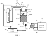
- FIG. 1 is a block diagram illustrating a trace gas measurement apparatus that can be implemented within one or more embodiments of the present invention.
- the trace gas measurement apparatus 100 is connectable to and communicates directly with electrical equipment 40. This communication may be performed in real-time, on-line during operation of the electrical equipment 40.
- the trace gas measurement apparatus 100 may be disposed in direct contact with the electrical equipment 40 or in a remote location while maintaining communication with the electrical equipment 40.
- the present invention is not limited to the trace gas measurement apparatus 100 being disposed in any particular location, the location may be any location suitable for the purposes set forth herein. Further, the present invention is not limited to the electrical equipment including any particular type or number of electrical equipment components (e.g., transformers, tap changers, and/or circuit breakers), and may vary accordingly.
- electrical equipment including any particular type or number of electrical equipment components (e.g., transformers, tap changers, and/or circuit breakers), and may vary accordingly.
- the trace gas measurement apparatus 100 includes at least one sample cell 200 corresponding to and connectable to the electrical equipment 40, and including a head space 203 and an oil sample 205 housed therein.
- the sample cell 200 collects the oil sample 205 of insulating oil flowing through the electrical equipment 40, from which trace gases 206 such as methane, ethane, ethylene, acetylene, carbon monoxide and carbon dioxide are to be extracted for analysis.
- trace gases 206 such as methane, ethane, ethylene, acetylene, carbon monoxide and carbon dioxide are to be extracted for analysis.
- a laser-based sensor or other sensor system may be employed for receiving the trace gases 206 from the sample cell 200 and performing the trace gas detection process, to determine the health of the electrical equipment 40.
- the trace gas measurement apparatus 100 further includes an oil pump 108 connected with the sample cell 200 for selectively pumping oil into or out of the sample cell when necessary, via forward and return oil flow lines 50 and 60 connecting to the electrical equipment 40.
- the forward and return oil flow lines 50 and 60 respectively including valves 52 and 62, for controlling the flow of oil to the oil pump 108 from the electrical equipment 40, and from the oil pump 108 to the electrical equipment 40.
- the oil pump 108 is a reversible type oil pump for selectively reversing the operation thereof, to either pump oil into or out of the sample cell 200.
- the oil pump 108 is not limited to any particular type of reversible pump. Further, alternatively, separate pumps may be used to separately pump oil into and out of the sample cell 200. Any pump(s) suitable for the purpose set forth herein may be employed.
- valves 52 and 62 are non-reversible valves (NRVs) which prevent oil being supplied from the electrical equipment 40 or to the electrical equipment 40 from reversing in direction and causing damage to the extraction process.
- NSVs non-reversible valves
- the present invention is not limited to any particular type or number of valves, any type or number of valves suitable for the purpose set forth herein may be employed.
- a plurality of valves 110 and 112 within respective forward and return gas paths 115 and 118 are provided.
- the forward and return gas paths 115 and 118 connect the sample cell 200 to an analysis module 120, for performing measurements and analysis on trace gases 206 extracted within the sample cell 200.
- the analysis module 120 includes a measure chamber 125 for receiving trace gases 206 therein, and performing DGA.
- a control mechanism (not shown) may be provided for controlling the stop and start of flow and amount of flow within the forward and return paths 115 and 118.
- a control module 130 is also provided in communication with the analysis module 120, and oil pump 108 and controls operations within the trace gas measurement apparatus 100.
- the oil sample 205 in the sample cell 200 is supplied via the forward flow line 50 from the electrical equipment 40 to the sample cell 200 during operation of the trace gas measurement apparatus 100.
- the oil sample 205 resides in the sample cell 200 for a predetermined period of time during which a measurement and analysis operation is to be performed.
- a single sample cell 200 is provided, a plurality of sample cells 200 may be provided to accommodate multiple electrical equipment components as needed. Alternatively, multiple electrical equipment components may be connected to a single sample cell 200.
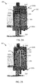
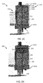
- FIGs. 2A through 2D are detailed schematics of a sample cell 200 which may be employed within the trace gas measurement apparatus 100 of FIG. 1 , illustrating operations thereof that can be implemented within one or more embodiments of the present invention.
- the sample cell 200 comprises a housing 202 having a lower section 202a and an upper section 202b, for housing an oil sample 205 therein.
- the oil sample 205 enters the sample cell 200 through an opening in the lower section 202a.
- the sample cell 200 further includes a plurality of perforated sheets 210 including 210a, 210b and 210c disposed in a fixed horizontal manner by a fixing means (not shown) within the upper section 202b of the housing 202 in the head space region 203.
- the perforated sheets 210 are spaced a predetermined distance apart.
- An oil receiving portion 215 extends in a vertical direction through the housing 202, and receives new oil samples from the electrical equipment 40 via line 109 as depicted in FIG. 1 .
- the oil receiving portion 215 may be in the form of a tube or piping for receiving and transmitting oil to the sample cell 200.
- a separate oil output portion 218 is also included in the sample cell 200 for outputting existing oil samples from the sample cell 200. The inputting of new oil samples and outputting of existing oil samples is controlled by the control module 130 (as depicted in FIG. 1 ).
- valve 52 in operation of the sample cell 200, valve 52 (as depicted in FIG. 1 ) is open to allow an oil sample 205 from the electrical equipment 40 to be drawn and pumped via the oil pump 108 into the sample cell 200.
- oil portions 230a, 230b and 230c of the oil sample 230 are pumped successively via the oil pump 108 through the oil receiving portion 215 and into the upper section 205b (see arrows 'A') and are disposed on the first, second and third perforated sheets 210a, 210b and 210c.
- the weight of the oil portion 230a pushes the first perforated sheet 210a towards a top surface of the existing oil sample 205 and rest thereon, forming a liquid film on the sheet 210a.
- the surface area i.e., the head space 203 as depicted in FIG. 2B ) for the extraction process is minimized since the oil level is at its maximum level.
- the perforated sheets 210 prevent the new oil sample 230 from comingling and recirculation with the existing oil sample 205.
- the present invention is not limited to any particular number or type of perforated sheets and may vary accordingly.
- the perforated sheets may be bent perforated sheets (e.g., an upturned U shape) arranged in a circular form or a stack of perforated sheets as shown in FIG. 2A .
- the existing oil sample 205 is pumped out from oil output portion 218 in the lower section 202a of the housing 202, leaving the new oil sample 230 in the sample cell 200. Then, the oil remaining in the sample cell 200 is equalised, to thereby obtain trace gases 206 (as depicted in FIG. 1 ).
- the process is repeated multiple cycles by adding new oil sample 230 and pumping out existing oil sample 205 and extracting trace gases 206 (as depicted in FIG. 1 ) from the oil sample remaining in the sample cell 200.
- the oil pump 108 as depicted in FIG. 1 , provides a volume pressure which further assist in extracting gas from the oil samples 205, 230.
- the present invention provides the advantage of being able to extract an increased amount of trace gases including hydrogen gas.
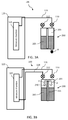
- FIGs. 3A through 3F are block diagrams of the trace gas measurement apparatus of FIG. 1 , illustrating trace gas extraction operations using air exhausted from the sample cell that can be implemented within one or more embodiments of the present invention.
- a flushing operation is performed by inputting a new ambient gas sample (i.e., atmospheric air sample) which contains a minimal amount of trace gases, e.g., zero (0) parts per million (ppm) of acetylene, into the apparatus 100 via the ambient valve 112.
- a new ambient gas sample i.e., atmospheric air sample
- trace gases e.g., zero (0) parts per million (ppm) of acetylene
- the oil level is dropped in the sample cell 200 by pumping the oil out (as depicted by arrow 'B') and the ambient valve 112 is opened to receive the air sample, and air within the measure chamber 125 is also drawn into the sample cell 200 via the exhaust valve 110.
- exhaust valve 110 After measuring the trace gases (not shown) within the air sample, to exhaust the air sample, exhaust valve 110 is opened, air is pushed out through the exhaust valve 110 by filling the oil level with new oil 230 as shown in FIG. 3B (see arrows 'A').
- the trace gas measurement apparatus 100 further includes a hydrogen (H2) sensor 300 within the exhaust path.
- the hydrogen gas sensor 300 is in ambient air within an enclosed volume having a small opening to allow the hydrogen gas sensor to be recharged by atmospheric levels of gases (i.e., oxygen).
- the pressure within the sample cell 200 pushes air flow within the head space 203 through the exhaust valve 110 and into the hydrogen gas sensor 300.
- the pressure may be approximately 1.1 bar.
- the pressure within the sample cell 200 is not limited hereto and may vary as necessary.
- the hydrogen gas sensor 300 is sensitive to flow velocities, applying a small amount of pressure increase of approximately 0.1 bar over ambient will enable control thereof.
- the exhaust valve 110 is opened for a predetermined time to exhaust air (see arrows), for example, approximately 0.25 seconds to approximately 30 seconds for a plurality of increments, to determine the concentration of hydrogen gas in the air exhausted.
- a predetermined time for example, approximately 0.25 seconds to approximately 30 seconds for a plurality of increments.
- the exhaust valve 110 is closed and the trace gas measurement apparatus 100 monitors the rise and decay within the hydrogen gas sensor 300 and reads the peak measurement at the dilution of the volume within the hydrogen gas sensor 300 during the plurality of increments.
- the extraction of other trace gases is performed by adding new oil sample 230 into the sample cell 200 via the oil receiving portion 215 (see arrows 'A') and the sample cell 200 is filled to the top surface, and removing existing oil from the sample cell 200 using the oil output portion 218, continuously repeating multiple cycles, to allow trace gases to be extracted from the oil in the sample cell 200 as desired, at a lower detection limit (LDL) such as approximately 1 ppm (parts per million).
- LDL lower detection limit
- the oil level within the sample cell 200 may be adjusted along with other measuring parameter such as the air pressure within the sample cell 200, in order to extract the trace gases from the oil at a higher detection limit (HDL) for example, approximately 50,000 ppm.
- HDL detection limit
- the control module 130 includes a microcontroller or microprocessor programmed with computer software for controlling the extraction process and performing analysis of the trace gases 206 when supplied to the analysis module 120.
- the control module 130 controls the operation of the analysis module 120 and the oil pump 108.
- the control module 130 may be any type of computing device capable of performing the operations of the present invention.
- FIG. 4 is a flow diagram illustrating an exemplary hydrogen gas extraction method 400 as illustrated in FIGs. 3A through 3F , implementing an embodiment of the present invention.
- the process begins at operation 410, where an ambient gas sample containing trace gases is input into the sample cell of the trace gas measurement apparatus ( FIG. 3A ).
- the process continues to operation 420, where the oil level is dropped in the sample cell ( FIG. 3A ) and air within the analysis module is drawn into the sample cell to perform ( FIG. 3B ), and a measurement of the trace gases within the air sample is performed.
- the exhaust valve is opened for a predetermine time period to determine a concentration of hydrogen gas therein ( FIG. 3E ).
- the exhaust valve is closed and the rise and decay in the hydrogen gas sensor is measured and the peak measurement is taken during an application of dilution of the sensor volume for example, two times, three times, etc. ( FIG. 3F ).
- the exhaust valve is opened and closed in several increments each for a predetermined period of time such as 0.25 seconds in order to determine the concentration of hydrogen gas within the hydrogen gas sensor.
- a predetermined period of time such as 0.25 seconds
- the present invention is not limited to any particular number of increments or any particular predetermined time period and may vary accordingly.
- the sample cell is then filled with new oil, existing oil is withdrawn from an oil output portion to a predetermined level, and the air pressure is adjusted to measure trace gases within the oil in the sample cell.
- the exhaust valve is opened to allow the filled oil chamber to be at approximately 1 bar absolute, before repeating the process.
- the trace gas measurement apparatus of the present invention may be used in an on line measurement type arrangement with electrical equipment such as a main transformer and/or tank changer.
- the measurement apparatus may further be implemented in real-time to determine the condition of the total electrical system (e.g., a transformer system). These faults can be detected early, to minimize cost associated with unplanned outages and any electrical equipment failure.
Landscapes
- Chemical & Material Sciences (AREA)
- Health & Medical Sciences (AREA)
- Life Sciences & Earth Sciences (AREA)
- Physics & Mathematics (AREA)
- Engineering & Computer Science (AREA)
- Analytical Chemistry (AREA)
- General Physics & Mathematics (AREA)
- Pathology (AREA)
- Immunology (AREA)
- Biochemistry (AREA)
- General Health & Medical Sciences (AREA)
- Food Science & Technology (AREA)
- Medicinal Chemistry (AREA)
- Chemical Kinetics & Catalysis (AREA)
- Oil, Petroleum & Natural Gas (AREA)
- General Chemical & Material Sciences (AREA)
- Biomedical Technology (AREA)
- Molecular Biology (AREA)
- Optics & Photonics (AREA)
- Acoustics & Sound (AREA)
- Combustion & Propulsion (AREA)
- Sampling And Sample Adjustment (AREA)
Applications Claiming Priority (1)
| Application Number | Priority Date | Filing Date | Title |
|---|---|---|---|
| US14/669,871 US10024836B2 (en) | 2015-03-26 | 2015-03-26 | Trace gas measurement apparatus for electrical equipment |
Publications (2)
| Publication Number | Publication Date |
|---|---|
| EP3073261A1 true EP3073261A1 (fr) | 2016-09-28 |
| EP3073261B1 EP3073261B1 (fr) | 2018-03-07 |
Family
ID=55589705
Family Applications (1)
| Application Number | Title | Priority Date | Filing Date |
|---|---|---|---|
| EP16161512.5A Active EP3073261B1 (fr) | 2015-03-26 | 2016-03-22 | Appareil de mesure de traces de gaz pour équipement électrique |
Country Status (5)
| Country | Link |
|---|---|
| US (1) | US10024836B2 (fr) |
| EP (1) | EP3073261B1 (fr) |
| CN (1) | CN106018676A (fr) |
| BR (1) | BR102016005990A2 (fr) |
| CA (1) | CA2923936C (fr) |
Cited By (2)
| Publication number | Priority date | Publication date | Assignee | Title |
|---|---|---|---|---|
| CN107449694A (zh) * | 2017-07-19 | 2017-12-08 | 上海化工研究院有限公司 | 称重式微量气体体积测定装置及基于该装置的测试方法 |
| EP3076172B1 (fr) * | 2015-04-02 | 2018-08-15 | General Electric Company | Appareil de mesure de gaz à l'état de traces pour matériel électrique |
Families Citing this family (8)
| Publication number | Priority date | Publication date | Assignee | Title |
|---|---|---|---|---|
| US10024836B2 (en) * | 2015-03-26 | 2018-07-17 | General Electric Company | Trace gas measurement apparatus for electrical equipment |
| JP6685247B2 (ja) * | 2017-02-10 | 2020-04-22 | 三菱電機株式会社 | ガス監視装置付き油入変圧器 |
| JP6921012B2 (ja) * | 2018-01-23 | 2021-08-18 | 三菱電機株式会社 | 油中ガス分析装置、これを備える油中ガス分析システム、および、油中ガス分析装置を用いて行なわれる油中ガス分析方法 |
| JP7048923B2 (ja) * | 2018-03-16 | 2022-04-06 | 有限会社プレスト | 油中水分検知装置 |
| US11137382B2 (en) | 2018-06-15 | 2021-10-05 | Morgan Schaffer Ltd. | Apparatus and method for performing gas analysis using optical absorption spectroscopy, such as infrared (IR) and/or UV, and use thereof in apparatus and method for performing dissolved gas analysis (DGA) on a piece of electrical equipment |
| CA3089773C (fr) | 2019-10-08 | 2025-06-17 | Morgan Schaffer Ltd. | Étalonnage d’un système d’analyse de gaz dissous |
| CN113294411B (zh) * | 2021-04-29 | 2023-11-07 | 中国航空工业集团公司金城南京机电液压工程研究中心 | 一种基于音圈元件的排气装置及方法 |
| CN117191499B (zh) * | 2023-11-03 | 2024-01-30 | 南通臻泓环保设备制造有限公司 | 一种罐装气体生产用的取样装置 |
Citations (5)
| Publication number | Priority date | Publication date | Assignee | Title |
|---|---|---|---|---|
| JPS60253842A (ja) * | 1984-05-30 | 1985-12-14 | Mitsubishi Electric Corp | 油中溶解ガス監視装置 |
| US4944178A (en) * | 1988-04-18 | 1990-07-31 | Nissin Electric Co., Ltd | Apparatus and method for measuring dissolved gas in oil |
| DE19503802C1 (de) * | 1995-02-06 | 1996-03-14 | Siemens Ag | Vorrichtung zur Bestimmung des Wasserstoffgehalts in Trafoöl |
| US20030172716A1 (en) * | 2000-05-10 | 2003-09-18 | Eckhard Braesel | Method and device for the monitoring of gases |
| EP1790965A1 (fr) * | 2005-11-29 | 2007-05-30 | Bräsel, Eckhard | Procédé de mise à disposition de gaz libérés dans des liquides d'installations à haute tension pour l'analyse externe et dispositif pour la réalisation du procédé |
Family Cites Families (31)
| Publication number | Priority date | Publication date | Assignee | Title |
|---|---|---|---|---|
| US3779066A (en) | 1971-01-26 | 1973-12-18 | Us Agriculture | Determination of residual solvent in oilseed meals and flours by a volatilization procedure |
| US4385634A (en) * | 1981-04-24 | 1983-05-31 | University Of Arizona Foundation | Radiation-induced thermoacoustic imaging |
| US4890478A (en) | 1987-09-11 | 1990-01-02 | Westinghouse Electric Corp. | Gas-in-oil monitoring apparatus and method |
| US5633711A (en) * | 1991-07-08 | 1997-05-27 | Massachusettes Institute Of Technology | Measurement of material properties with optically induced phonons |
| SE9102770L (sv) * | 1991-09-25 | 1993-03-26 | Asea Brown Boveri | Oevervakning av loest gas i olja |
| US5400641A (en) | 1993-11-03 | 1995-03-28 | Advanced Optical Controls, Inc. | Transformer oil gas extractor |
| US6037592A (en) * | 1997-02-14 | 2000-03-14 | Underground Systems, Inc. | System for measuring gases dissolved in a liquid |
| US5749942A (en) | 1997-02-14 | 1998-05-12 | Raychem Corporation | Apparatus for extracting a gas from a liquid and delivering the gas to a collection station |
| DE19833601C1 (de) * | 1998-07-25 | 1999-12-23 | Eckhard Braesel | Verfahren zur Feststellung und Herkunftsbestimmung ungelöster Gase in mit Flüssigkeit gefüllten Hochspannungsanlagen und Vorrichtungen zur Durchführung des Verfahrens |
| US6289716B1 (en) * | 1998-08-19 | 2001-09-18 | Electric Power Research Institute, Inc. | Method for on-line assessment and indication of transformer conditions |
| US6277329B1 (en) * | 1999-03-22 | 2001-08-21 | Camp Dresser & Mckee Inc. | Dissolved hydrogen analyzer |
| US6391096B1 (en) * | 2000-06-09 | 2002-05-21 | Serveron Corporation | Apparatus and method for extracting and analyzing gas |
| US6742384B2 (en) | 2002-07-02 | 2004-06-01 | Carrier Corporation | Trace gas management system for leak detection operations |
| GB0606976D0 (en) * | 2006-04-07 | 2006-05-17 | Kelman Ltd | Apparatus for performing dissolved gas analysis |
| JP2007309770A (ja) * | 2006-05-18 | 2007-11-29 | Hitachi Ltd | 油中ガス分析装置、油中ガス分析装置を備えた変圧器、及び油中ガスの分析方法 |
| US8075675B2 (en) * | 2008-06-12 | 2011-12-13 | Serveron Corporation | Apparatus and method for extracting gas from liquid |
| US8028561B2 (en) * | 2008-09-30 | 2011-10-04 | Qualitrol Company, Llc | Hydrogen sensor with air access |
| US8040518B2 (en) | 2008-10-07 | 2011-10-18 | Entanglement Technologies, Inc. | Cavity enhanced trace gas detection gradiometer |
| IT1397471B1 (it) * | 2010-01-14 | 2013-01-16 | Techimp Technologies S A Ora Techimp Technologies S R L | Procedimento e dispositivo per derivare la concentrazione di un gas disciolto in un olio di isolamento elettrico. |
| US8196448B2 (en) * | 2010-01-20 | 2012-06-12 | GM Global Technology Operations LLC | Hydrogen sensor assembly |
| US8442775B2 (en) * | 2010-04-02 | 2013-05-14 | Eduardo Pedrosa Santos | System and method for monitoring dissolved gases in insulating oil of high voltage equipment |
| US8395777B2 (en) | 2010-09-09 | 2013-03-12 | Adelphi University | Method and apparatus for trace gas detection using integrated wavelength modulated spectra across multiple lines |
| WO2012100246A1 (fr) * | 2011-01-23 | 2012-07-26 | Bpl Global, Ltd. | Dispositif d'échantillonnage d'huile d'appareil électrique et conditionneur pour capteurs à semi-conducteurs |
| US8707767B2 (en) | 2011-03-31 | 2014-04-29 | Qualitrol Company, Llc | Combined hydrogen and pressure sensor assembly |
| US9176107B2 (en) * | 2012-02-01 | 2015-11-03 | Lumasense Technologies Holdings, Inc. | System and method for monitoring asset health by dissolved gas measurement |
| EP2762857B1 (fr) * | 2012-12-19 | 2018-05-02 | General Electric Company | Procédé et dispositif d'analyse de gaz dissous |
| EP2746747A1 (fr) * | 2012-12-21 | 2014-06-25 | ABB Research Ltd. | Ensemble capteur et procédé pour déterminer la teneur en humidité et hydrogène de l'huile de transformateur |
| EP2778660A1 (fr) | 2013-03-15 | 2014-09-17 | ABB Research Ltd. | Ensemble capteur et procédé pour détecter un état de statut d'équipement électrique |
| JP6165343B2 (ja) * | 2013-09-12 | 2017-07-19 | コリア・アドバンスト・インスティテュート・オブ・サイエンス・アンド・テクノロジー | 液体内の溶存水素ガス濃度測定用水素センサ素子およびこれを用いた水素ガス濃度測定方法 |
| ES2632612T3 (es) | 2014-08-19 | 2017-09-14 | Abb Schweiz Ag | Sensor óptico para detectar hidrógeno en fluido y uso de una película de aleación fina en el sensor de hidrógeno |
| US10024836B2 (en) * | 2015-03-26 | 2018-07-17 | General Electric Company | Trace gas measurement apparatus for electrical equipment |
-
2015
- 2015-03-26 US US14/669,871 patent/US10024836B2/en active Active
-
2016
- 2016-03-17 CA CA2923936A patent/CA2923936C/fr active Active
- 2016-03-18 BR BR102016005990A patent/BR102016005990A2/pt not_active IP Right Cessation
- 2016-03-22 EP EP16161512.5A patent/EP3073261B1/fr active Active
- 2016-03-24 CN CN201610172056.4A patent/CN106018676A/zh active Pending
Patent Citations (5)
| Publication number | Priority date | Publication date | Assignee | Title |
|---|---|---|---|---|
| JPS60253842A (ja) * | 1984-05-30 | 1985-12-14 | Mitsubishi Electric Corp | 油中溶解ガス監視装置 |
| US4944178A (en) * | 1988-04-18 | 1990-07-31 | Nissin Electric Co., Ltd | Apparatus and method for measuring dissolved gas in oil |
| DE19503802C1 (de) * | 1995-02-06 | 1996-03-14 | Siemens Ag | Vorrichtung zur Bestimmung des Wasserstoffgehalts in Trafoöl |
| US20030172716A1 (en) * | 2000-05-10 | 2003-09-18 | Eckhard Braesel | Method and device for the monitoring of gases |
| EP1790965A1 (fr) * | 2005-11-29 | 2007-05-30 | Bräsel, Eckhard | Procédé de mise à disposition de gaz libérés dans des liquides d'installations à haute tension pour l'analyse externe et dispositif pour la réalisation du procédé |
Cited By (2)
| Publication number | Priority date | Publication date | Assignee | Title |
|---|---|---|---|---|
| EP3076172B1 (fr) * | 2015-04-02 | 2018-08-15 | General Electric Company | Appareil de mesure de gaz à l'état de traces pour matériel électrique |
| CN107449694A (zh) * | 2017-07-19 | 2017-12-08 | 上海化工研究院有限公司 | 称重式微量气体体积测定装置及基于该装置的测试方法 |
Also Published As
| Publication number | Publication date |
|---|---|
| US20160282323A1 (en) | 2016-09-29 |
| BR102016005990A2 (pt) | 2016-09-27 |
| CA2923936C (fr) | 2023-10-24 |
| US10024836B2 (en) | 2018-07-17 |
| EP3073261B1 (fr) | 2018-03-07 |
| CN106018676A (zh) | 2016-10-12 |
| CA2923936A1 (fr) | 2016-09-26 |
Similar Documents
| Publication | Publication Date | Title |
|---|---|---|
| CA2923936C (fr) | Appareil de mesure de gaz a l'etat de traces destine a un equipement electrique | |
| Arakelian | Effective diagnostics for oil-filled equipment | |
| EP2008076B1 (fr) | Appareil de réalisation d'une analyse d'un gaz dissout | |
| CN210487949U (zh) | 油浸式高压设备的油光声光谱在线监测装置 | |
| EP3076172B1 (fr) | Appareil de mesure de gaz à l'état de traces pour matériel électrique | |
| US20140053626A1 (en) | System and method for monitoring asset health by dissolved gas measurement | |
| CN103149345B (zh) | 一种油中溶解气体智能组件的检验方法及装置 | |
| CN111999355A (zh) | 一种变压器可燃气体在线检测装置及方法 | |
| EP3073248A1 (fr) | Appareil de mesure de traces de gaz pour matériel électrique | |
| CN110779966B (zh) | 轻瓦斯告警特征气体检测方法及装置 | |
| JP3343524B2 (ja) | 電気絶縁油中ガスの分析装置 | |
| JP2009189182A (ja) | 開閉装置 | |
| JP2015165553A (ja) | 油入電気機器の診断方法、油入電気機器の診断装置、および、それを備えた油入電気機器 | |
| CN105259260B (zh) | 一种具有三通阀的变压器油色谱在线监测装置 | |
| Azirani et al. | Online Fault Gas Monitoring System for Hermetically Sealed Power Transformers | |
| JP3652792B2 (ja) | 油入電気機器診断方法及びこれの携帯用診断器 | |
| JP2777304B2 (ja) | パーフルオロカーボン入電気装置の異常診断装置および診断方法 | |
| CN116519858B (zh) | 一种带实时监测的变压器油护理装置 | |
| JP2017130565A (ja) | 油入電気機器の異常診断装置および異常診断方法 | |
| US12629613B2 (en) | Apparatus and method for degassing a device, and corresponding test system for gas analysis | |
| CN112213277A (zh) | 油浸式设备油路控制方法及装置 | |
| CN203101378U (zh) | 一种油中溶解气体智能组件的检验装置 | |
| JP5806475B2 (ja) | 油入電気機器の異常診断装置および異常診断方法 | |
| KR101126462B1 (ko) | 절연유내의 잔여 가스압 측정장치 | |
| US20230390668A1 (en) | Apparatus and method for degassing a device, and corresponding test system for gas analysis |
Legal Events
| Date | Code | Title | Description |
|---|---|---|---|
| PUAI | Public reference made under article 153(3) epc to a published international application that has entered the european phase |
Free format text: ORIGINAL CODE: 0009012 |
|
| AK | Designated contracting states |
Kind code of ref document: A1 Designated state(s): AL AT BE BG CH CY CZ DE DK EE ES FI FR GB GR HR HU IE IS IT LI LT LU LV MC MK MT NL NO PL PT RO RS SE SI SK SM TR |
|
| AX | Request for extension of the european patent |
Extension state: BA ME |
|
| 17P | Request for examination filed |
Effective date: 20170328 |
|
| RBV | Designated contracting states (corrected) |
Designated state(s): AL AT BE BG CH CY CZ DE DK EE ES FI FR GB GR HR HU IE IS IT LI LT LU LV MC MK MT NL NO PL PT RO RS SE SI SK SM TR |
|
| 17Q | First examination report despatched |
Effective date: 20170512 |
|
| GRAP | Despatch of communication of intention to grant a patent |
Free format text: ORIGINAL CODE: EPIDOSNIGR1 |
|
| RIC1 | Information provided on ipc code assigned before grant |
Ipc: G01N 1/22 20060101ALI20170914BHEP Ipc: G01N 33/28 20060101AFI20170914BHEP |
|
| INTG | Intention to grant announced |
Effective date: 20171017 |
|
| GRAS | Grant fee paid |
Free format text: ORIGINAL CODE: EPIDOSNIGR3 |
|
| GRAA | (expected) grant |
Free format text: ORIGINAL CODE: 0009210 |
|
| AK | Designated contracting states |
Kind code of ref document: B1 Designated state(s): AL AT BE BG CH CY CZ DE DK EE ES FI FR GB GR HR HU IE IS IT LI LT LU LV MC MK MT NL NO PL PT RO RS SE SI SK SM TR |
|
| REG | Reference to a national code |
Ref country code: GB Ref legal event code: FG4D |
|
| REG | Reference to a national code |
Ref country code: CH Ref legal event code: EP Ref country code: AT Ref legal event code: REF Ref document number: 977115 Country of ref document: AT Kind code of ref document: T Effective date: 20180315 |
|
| REG | Reference to a national code |
Ref country code: FR Ref legal event code: PLFP Year of fee payment: 3 |
|
| REG | Reference to a national code |
Ref country code: IE Ref legal event code: FG4D |
|
| REG | Reference to a national code |
Ref country code: DE Ref legal event code: R096 Ref document number: 602016001774 Country of ref document: DE |
|
| REG | Reference to a national code |
Ref country code: SE Ref legal event code: TRGR |
|
| REG | Reference to a national code |
Ref country code: NL Ref legal event code: MP Effective date: 20180307 |
|
| REG | Reference to a national code |
Ref country code: LT Ref legal event code: MG4D |
|
| PG25 | Lapsed in a contracting state [announced via postgrant information from national office to epo] |
Ref country code: LT Free format text: LAPSE BECAUSE OF FAILURE TO SUBMIT A TRANSLATION OF THE DESCRIPTION OR TO PAY THE FEE WITHIN THE PRESCRIBED TIME-LIMIT Effective date: 20180307 Ref country code: CY Free format text: LAPSE BECAUSE OF FAILURE TO SUBMIT A TRANSLATION OF THE DESCRIPTION OR TO PAY THE FEE WITHIN THE PRESCRIBED TIME-LIMIT Effective date: 20180307 Ref country code: HR Free format text: LAPSE BECAUSE OF FAILURE TO SUBMIT A TRANSLATION OF THE DESCRIPTION OR TO PAY THE FEE WITHIN THE PRESCRIBED TIME-LIMIT Effective date: 20180307 Ref country code: ES Free format text: LAPSE BECAUSE OF FAILURE TO SUBMIT A TRANSLATION OF THE DESCRIPTION OR TO PAY THE FEE WITHIN THE PRESCRIBED TIME-LIMIT Effective date: 20180307 Ref country code: FI Free format text: LAPSE BECAUSE OF FAILURE TO SUBMIT A TRANSLATION OF THE DESCRIPTION OR TO PAY THE FEE WITHIN THE PRESCRIBED TIME-LIMIT Effective date: 20180307 Ref country code: NO Free format text: LAPSE BECAUSE OF FAILURE TO SUBMIT A TRANSLATION OF THE DESCRIPTION OR TO PAY THE FEE WITHIN THE PRESCRIBED TIME-LIMIT Effective date: 20180607 |
|
| REG | Reference to a national code |
Ref country code: AT Ref legal event code: MK05 Ref document number: 977115 Country of ref document: AT Kind code of ref document: T Effective date: 20180307 |
|
| PG25 | Lapsed in a contracting state [announced via postgrant information from national office to epo] |
Ref country code: LV Free format text: LAPSE BECAUSE OF FAILURE TO SUBMIT A TRANSLATION OF THE DESCRIPTION OR TO PAY THE FEE WITHIN THE PRESCRIBED TIME-LIMIT Effective date: 20180307 Ref country code: RS Free format text: LAPSE BECAUSE OF FAILURE TO SUBMIT A TRANSLATION OF THE DESCRIPTION OR TO PAY THE FEE WITHIN THE PRESCRIBED TIME-LIMIT Effective date: 20180307 Ref country code: GR Free format text: LAPSE BECAUSE OF FAILURE TO SUBMIT A TRANSLATION OF THE DESCRIPTION OR TO PAY THE FEE WITHIN THE PRESCRIBED TIME-LIMIT Effective date: 20180608 Ref country code: BG Free format text: LAPSE BECAUSE OF FAILURE TO SUBMIT A TRANSLATION OF THE DESCRIPTION OR TO PAY THE FEE WITHIN THE PRESCRIBED TIME-LIMIT Effective date: 20180607 |
|
| PG25 | Lapsed in a contracting state [announced via postgrant information from national office to epo] |
Ref country code: AL Free format text: LAPSE BECAUSE OF FAILURE TO SUBMIT A TRANSLATION OF THE DESCRIPTION OR TO PAY THE FEE WITHIN THE PRESCRIBED TIME-LIMIT Effective date: 20180307 Ref country code: PL Free format text: LAPSE BECAUSE OF FAILURE TO SUBMIT A TRANSLATION OF THE DESCRIPTION OR TO PAY THE FEE WITHIN THE PRESCRIBED TIME-LIMIT Effective date: 20180307 Ref country code: NL Free format text: LAPSE BECAUSE OF FAILURE TO SUBMIT A TRANSLATION OF THE DESCRIPTION OR TO PAY THE FEE WITHIN THE PRESCRIBED TIME-LIMIT Effective date: 20180307 Ref country code: IT Free format text: LAPSE BECAUSE OF FAILURE TO SUBMIT A TRANSLATION OF THE DESCRIPTION OR TO PAY THE FEE WITHIN THE PRESCRIBED TIME-LIMIT Effective date: 20180307 Ref country code: RO Free format text: LAPSE BECAUSE OF FAILURE TO SUBMIT A TRANSLATION OF THE DESCRIPTION OR TO PAY THE FEE WITHIN THE PRESCRIBED TIME-LIMIT Effective date: 20180307 Ref country code: EE Free format text: LAPSE BECAUSE OF FAILURE TO SUBMIT A TRANSLATION OF THE DESCRIPTION OR TO PAY THE FEE WITHIN THE PRESCRIBED TIME-LIMIT Effective date: 20180307 |
|
| PG25 | Lapsed in a contracting state [announced via postgrant information from national office to epo] |
Ref country code: SK Free format text: LAPSE BECAUSE OF FAILURE TO SUBMIT A TRANSLATION OF THE DESCRIPTION OR TO PAY THE FEE WITHIN THE PRESCRIBED TIME-LIMIT Effective date: 20180307 Ref country code: CZ Free format text: LAPSE BECAUSE OF FAILURE TO SUBMIT A TRANSLATION OF THE DESCRIPTION OR TO PAY THE FEE WITHIN THE PRESCRIBED TIME-LIMIT Effective date: 20180307 Ref country code: SM Free format text: LAPSE BECAUSE OF FAILURE TO SUBMIT A TRANSLATION OF THE DESCRIPTION OR TO PAY THE FEE WITHIN THE PRESCRIBED TIME-LIMIT Effective date: 20180307 Ref country code: AT Free format text: LAPSE BECAUSE OF FAILURE TO SUBMIT A TRANSLATION OF THE DESCRIPTION OR TO PAY THE FEE WITHIN THE PRESCRIBED TIME-LIMIT Effective date: 20180307 |
|
| REG | Reference to a national code |
Ref country code: BE Ref legal event code: MM Effective date: 20180331 Ref country code: DE Ref legal event code: R097 Ref document number: 602016001774 Country of ref document: DE |
|
| REG | Reference to a national code |
Ref country code: IE Ref legal event code: MM4A |
|
| PG25 | Lapsed in a contracting state [announced via postgrant information from national office to epo] |
Ref country code: PT Free format text: LAPSE BECAUSE OF FAILURE TO SUBMIT A TRANSLATION OF THE DESCRIPTION OR TO PAY THE FEE WITHIN THE PRESCRIBED TIME-LIMIT Effective date: 20180709 Ref country code: LU Free format text: LAPSE BECAUSE OF NON-PAYMENT OF DUE FEES Effective date: 20180322 |
|
| PLBE | No opposition filed within time limit |
Free format text: ORIGINAL CODE: 0009261 |
|
| STAA | Information on the status of an ep patent application or granted ep patent |
Free format text: STATUS: NO OPPOSITION FILED WITHIN TIME LIMIT |
|
| PG25 | Lapsed in a contracting state [announced via postgrant information from national office to epo] |
Ref country code: MC Free format text: LAPSE BECAUSE OF FAILURE TO SUBMIT A TRANSLATION OF THE DESCRIPTION OR TO PAY THE FEE WITHIN THE PRESCRIBED TIME-LIMIT Effective date: 20180307 Ref country code: IE Free format text: LAPSE BECAUSE OF NON-PAYMENT OF DUE FEES Effective date: 20180322 Ref country code: DK Free format text: LAPSE BECAUSE OF FAILURE TO SUBMIT A TRANSLATION OF THE DESCRIPTION OR TO PAY THE FEE WITHIN THE PRESCRIBED TIME-LIMIT Effective date: 20180307 |
|
| 26N | No opposition filed |
Effective date: 20181210 |
|
| PG25 | Lapsed in a contracting state [announced via postgrant information from national office to epo] |
Ref country code: SI Free format text: LAPSE BECAUSE OF FAILURE TO SUBMIT A TRANSLATION OF THE DESCRIPTION OR TO PAY THE FEE WITHIN THE PRESCRIBED TIME-LIMIT Effective date: 20180307 Ref country code: BE Free format text: LAPSE BECAUSE OF NON-PAYMENT OF DUE FEES Effective date: 20180331 |
|
| REG | Reference to a national code |
Ref country code: CH Ref legal event code: PL |
|
| PG25 | Lapsed in a contracting state [announced via postgrant information from national office to epo] |
Ref country code: MT Free format text: LAPSE BECAUSE OF NON-PAYMENT OF DUE FEES Effective date: 20180322 Ref country code: LI Free format text: LAPSE BECAUSE OF NON-PAYMENT OF DUE FEES Effective date: 20190331 Ref country code: CH Free format text: LAPSE BECAUSE OF NON-PAYMENT OF DUE FEES Effective date: 20190331 |
|
| PG25 | Lapsed in a contracting state [announced via postgrant information from national office to epo] |
Ref country code: TR Free format text: LAPSE BECAUSE OF FAILURE TO SUBMIT A TRANSLATION OF THE DESCRIPTION OR TO PAY THE FEE WITHIN THE PRESCRIBED TIME-LIMIT Effective date: 20180307 |
|
| PG25 | Lapsed in a contracting state [announced via postgrant information from national office to epo] |
Ref country code: MK Free format text: LAPSE BECAUSE OF NON-PAYMENT OF DUE FEES Effective date: 20180307 Ref country code: HU Free format text: LAPSE BECAUSE OF FAILURE TO SUBMIT A TRANSLATION OF THE DESCRIPTION OR TO PAY THE FEE WITHIN THE PRESCRIBED TIME-LIMIT; INVALID AB INITIO Effective date: 20160322 |
|
| PG25 | Lapsed in a contracting state [announced via postgrant information from national office to epo] |
Ref country code: IS Free format text: LAPSE BECAUSE OF FAILURE TO SUBMIT A TRANSLATION OF THE DESCRIPTION OR TO PAY THE FEE WITHIN THE PRESCRIBED TIME-LIMIT Effective date: 20180707 |
|
| P01 | Opt-out of the competence of the unified patent court (upc) registered |
Effective date: 20230522 |
|
| REG | Reference to a national code |
Ref country code: DE Ref legal event code: R081 Ref document number: 602016001774 Country of ref document: DE Owner name: GENERAL ELECTRIC TECHNOLOGY GMBH, CH Free format text: FORMER OWNER: GENERAL ELECTRIC COMPANY, SCHENECTADY, NY, US |
|
| REG | Reference to a national code |
Ref country code: GB Ref legal event code: 732E Free format text: REGISTERED BETWEEN 20240222 AND 20240228 |
|
| PGFP | Annual fee paid to national office [announced via postgrant information from national office to epo] |
Ref country code: SE Payment date: 20260219 Year of fee payment: 11 |
|
| PGFP | Annual fee paid to national office [announced via postgrant information from national office to epo] |
Ref country code: GB Payment date: 20260219 Year of fee payment: 11 |
|
| PGFP | Annual fee paid to national office [announced via postgrant information from national office to epo] |
Ref country code: DE Payment date: 20260219 Year of fee payment: 11 |
|
| PGFP | Annual fee paid to national office [announced via postgrant information from national office to epo] |
Ref country code: FR Payment date: 20260219 Year of fee payment: 11 |