EP3073579A1 - Connecteur de cables sur plusieurs rangs - Google Patents
Connecteur de cables sur plusieurs rangs Download PDFInfo
- Publication number
- EP3073579A1 EP3073579A1 EP16159731.5A EP16159731A EP3073579A1 EP 3073579 A1 EP3073579 A1 EP 3073579A1 EP 16159731 A EP16159731 A EP 16159731A EP 3073579 A1 EP3073579 A1 EP 3073579A1
- Authority
- EP
- European Patent Office
- Prior art keywords
- leg
- passage openings
- cable
- cable plug
- openings
- Prior art date
- Legal status (The legal status is an assumption and is not a legal conclusion. Google has not performed a legal analysis and makes no representation as to the accuracy of the status listed.)
- Granted
Links
Images
Classifications
-
- H—ELECTRICITY
- H01—ELECTRIC ELEMENTS
- H01R—ELECTRICALLY-CONDUCTIVE CONNECTIONS; STRUCTURAL ASSOCIATIONS OF A PLURALITY OF MUTUALLY-INSULATED ELECTRICAL CONNECTING ELEMENTS; COUPLING DEVICES; CURRENT COLLECTORS
- H01R13/00—Details of coupling devices of the kinds covered by groups H01R12/70 or H01R24/00 - H01R33/00
- H01R13/46—Bases; Cases
- H01R13/50—Bases; Cases formed as an integral body
-
- H—ELECTRICITY
- H01—ELECTRIC ELEMENTS
- H01R—ELECTRICALLY-CONDUCTIVE CONNECTIONS; STRUCTURAL ASSOCIATIONS OF A PLURALITY OF MUTUALLY-INSULATED ELECTRICAL CONNECTING ELEMENTS; COUPLING DEVICES; CURRENT COLLECTORS
- H01R13/00—Details of coupling devices of the kinds covered by groups H01R12/70 or H01R24/00 - H01R33/00
- H01R13/56—Means for preventing chafing or fracture of flexible leads at outlet from coupling part
- H01R13/567—Traverse cable outlet or wire connection
-
- H—ELECTRICITY
- H01—ELECTRIC ELEMENTS
- H01R—ELECTRICALLY-CONDUCTIVE CONNECTIONS; STRUCTURAL ASSOCIATIONS OF A PLURALITY OF MUTUALLY-INSULATED ELECTRICAL CONNECTING ELEMENTS; COUPLING DEVICES; CURRENT COLLECTORS
- H01R13/00—Details of coupling devices of the kinds covered by groups H01R12/70 or H01R24/00 - H01R33/00
- H01R13/02—Contact members
- H01R13/025—Contact members formed by the conductors of a cable end
-
- H—ELECTRICITY
- H01—ELECTRIC ELEMENTS
- H01R—ELECTRICALLY-CONDUCTIVE CONNECTIONS; STRUCTURAL ASSOCIATIONS OF A PLURALITY OF MUTUALLY-INSULATED ELECTRICAL CONNECTING ELEMENTS; COUPLING DEVICES; CURRENT COLLECTORS
- H01R13/00—Details of coupling devices of the kinds covered by groups H01R12/70 or H01R24/00 - H01R33/00
- H01R13/40—Securing contact members in or to a base or case; Insulating of contact members
- H01R13/405—Securing in non-demountable manner, e.g. moulding, riveting
- H01R13/415—Securing in non-demountable manner, e.g. moulding, riveting by permanent deformation of contact member
Definitions
- the present invention relates to a cable connector having the features of claim 1. Accordingly, the present invention relates to a cable connector which is adapted to contact a contact arrangement (eg printed circuit board) with a plurality of juxtaposed contact rows in a simple and cost-effective manner.
- a contact arrangement eg printed circuit board
- beats DE 196 14 697 A1 For example, a connector in front of an insulated cable, which is inserted into a retaining clip and stripped from this and bent out again.
- the retaining clip ensures positioning of the cable.
- the stripped cable continues into snap-in bays resulting from the shape of the one-piece retaining clip.
- the cable end protruding from the retaining clip forms the actual plug contact, in particular for space-saving connection to a contact arrangement.
- a disadvantage of this embodiment remains the transport problem.
- the cable end protruding beyond the detent bays is only so long that it can assume a plug-in function, it is very susceptible to damage during transport operations.
- the geometric dimensions must always be optimized with regard to the tracking resistance.
- Decisive for the possible conditions of use for a particular group of insulating materials are, among other things, the constructive air and creepage distances, which are defined by the Isolier Sciencesgeometrie.
- the expert from the international Refer to the valid standards IEC 60664-1 and IEC 60004-5.
- the stripped cable ends emerging from the retaining clip are already close to each other before being inserted into the snap-in bays, so that there is always the danger of short circuits.
- a connector is used in particular as a soldering aid comprising at least one cable with insulation
- the stripped, optionally coated with solder end is designed as a plug contact element for contacting with another element with opposite contact elements such as a printed circuit board.
- the stripped cable is passed through a retaining clip positioned, wherein after exiting through an exit opening from the retaining clip, the remaining cable end is bent at an obtuse or right angle.
- the present invention seeks to provide a multi-row prefabricatable cable connector that can be used even in tight spaces, can be transported safely and is universally applicable. Furthermore, the object of the invention is to provide an optimized in terms of electrical safety cable connector, in which an optimal application of the rated voltage is possible, while at the same time space-saving design.
- the basic idea of the invention is that a cable plug with specifically designed and arranged passage openings is created, which are introduced in a preferably arranged in a diagonal offset grid in two L-shaped legs, wherein an opening for pushing through a stripped end of a single line is determined while the opening in alignment with this opening in the second leg is frontally open to bend the protruding stripped end of said single line and bring in a designated clamping position in which a protruding end portion protrudes from the underside of the insulating body of Kabeisteckers. Due to the mutual diagonal offset both in one and in turn in turn in the other leg one obtains a particularly compact design, in which the isolation characteristics such as creepage distances are optimized in relation to the total component size.
- Another advantage is that you can contact in a fixed grid without additional contact elements with a corresponding contact arrangement.
- the configuration according to the invention also requires no webs between the individual cables, since the Lines each closely adjacent or along the surface of the respective adjacent leg, so that damage is avoided constructively.
- a cable connector for direct connection of at least one multi-core line of insulated individual lines or for connecting a composite of insulated individual lines
- the cable connector is formed of an insulating body of two integrally connected legs, and extending the one leg in a vertical direction V. while the other leg extends in a horizontal direction H, wherein the leg extending in the vertical direction V has a plurality of juxtaposed passage openings which are provided in the vertical direction V in two mutually spaced horizontal planes H1, H2 and wherein the extending in the horizontal direction H second leg has a plurality of juxtaposed passage openings which are provided in the horizontal direction H in two mutually spaced vertical planes V1, V2.
- the lower passage openings of the first leg are arranged directly adjacent to the upper side of the second leg and / or the rear passage openings of the second leg are arranged directly adjacent to the front side of the first leg.
- the insulating body has a western L-shaped leg arrangement of the two legs, so that a compact design is achieved, which has a lower mounting pad.
- passage openings in the second leg are designed as passage openings which are open on one side to the front edge of the leg, so that fitting and cable mounting are particularly easy.
- the passage openings in the first leg are formed as passage openings which are closed circumferentially in the form of a cylinder.
- the passage opening (s) in the lower vertical plane V1 of the two vertical plane V1, V2 in the first leg in each case in alignment with one passage opening in the front horizontal plane H2 of the two horizontal planes H1, H2 in second legs are arranged.
- the passage opening (s) in the upper vertical plane V2 of the two vertical plane in the first leg in each case in alignment with one passage opening in the rear horizontal plane H2 of the two horizontal planes H1, H2 in the second leg are arranged.
- Also of advantage is an embodiment in which between at least two frontally open passage openings in the front horizontal plane H2 in the rear horizontal plane H1 frontally open passage opening is arranged, wherein preferably the distance between the upper passage opening (s) of the upper vertical plane V2 to the top of the second leg along the surface of the insulating body is approximately equal to the distance of the front passage opening (s) of the front horizontal plane H2 to the adjacent front side of the first leg along the surface of the insulating body.
- the passage openings and / or the passage openings in the diagonal offset are arranged in the respective leg, preferably in a symmetrically arranged diagonal offset.
- the width B of the front openings of the front openings in the second leg on the inlet side is less than or equal to the diameter D of the cylindrical receiving portion of the passages, which is intended for the stripped end of the male stripped individual line and preferably increases in the direction of the cylindrical receiving area or remains constant.
- the width B of the frontal openings of the rear passage openings in the second leg entry side is greater than the diameter D of the cylindrical receiving portion of the passage openings, which is intended for the stripped end of the male stripped individual line.
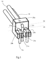
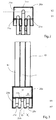
- FIGS. 1 to 3 is a smallest unit of a double-row cable plug 1 for direct connection of at least one multi-core cable of insulated individual lines 10 or for connection of a composite of insulated individual lines 10 with a conductor 10 a, which is surrounded by an insulating jacket shown.
- the cable connector 1 consists of an insulating body 2 of two integrally connected legs 20a, 20b.
- the one (first) leg 20a extends in a vertical direction V, while the other (second) leg 20b extends in the horizontal direction H.
- the insulating body 2 therefore has a western L-shaped leg arrangement of the two legs 20a, 20b.
- the extending in the vertical direction V leg 20a here shows three juxtaposed passage openings 21u, 21o, which are provided in the vertical direction V in two mutually spaced horizontal planes H1, H2.
- the horizontal planes H1 and H2 represent height-imaginary imaginary planes through the leg 20a which define the location of the passage openings (preferably the median planes through the passage openings).
- the extending in the horizontal direction H second leg 20b also shows three juxtaposed passage openings 21v, 21 h, which are provided in the horizontal direction H in two mutually spaced vertical planes V1, V2, which are also to be regarded as mid-planes through the openings.
- front and rear passage opening (s) 21v, 21h in the second leg 20b are designed as passage openings which are open on one side to the front leg edge 22. Further it can be seen that the passage openings 21u, 21o in the first leg 20a are formed as cylindrical peripherally closed passage openings.
- the two passage opening (s) 21 u in the lower vertical plane V1 of the two vertical plane V1, V2 in the first leg 20a are each aligned with one of the passage openings 21v in the front horizontal plane H2 of the two horizontal planes H1, H2 arranged in the second leg 20b ,
- the upper passage opening 21 o in the upper vertical plane V2 of the two vertical plane V1, V2 in the first leg 20a is arranged in alignment with the rear passage opening 21 h in the rear horizontal plane H2 of the two horizontal planes H1, H2 in the second leg 20b.
- the selected distance of the upper through opening 21 o of the upper vertical plane V2 to the upper side 23 b of the second leg 20 b along the surface of the insulating body is approximately equal to the distance of the front passage openings 21 v of the front horizontal plane H2 to the adjacent front side 23 a of the first leg 20 a along the surface of the Insulator 2.
- passage openings 21 u, 21 o and the passage openings 21 v, 21 h are arranged in the diagonal offset pattern in the respective legs 20 a, 20 b, in particular taking a wider embodiment into consideration, in which the unit shown here is the smallest Unit is visible and continues in the width direction so in the diagonal offset.
- the width B of the frontal openings 25v of the front passage openings 21v in the second leg 20b is slightly smaller than the diameter D of the cylindrical receiving area 25a of the passage openings 21v on the inlet side is, which is intended for the stripped end of the male stripped individual line. and preferably increases in the direction of the cylindrical receiving area or remains constant. It can also be seen that the width B of the end openings 25h of the rear passage openings 21h in the second leg 20b entry side is greater than the diameter D of the cylindrical receiving portion of the openings 21 h, which is determined for the stripped end of the male stripped individual line.
- the invention is not limited in its execution to the above-mentioned preferred embodiments. Rather, a number of variants is conceivable, which makes use of the illustrated solution even with fundamentally different types of use.
Landscapes
- Details Of Connecting Devices For Male And Female Coupling (AREA)
- Connector Housings Or Holding Contact Members (AREA)
Applications Claiming Priority (1)
| Application Number | Priority Date | Filing Date | Title |
|---|---|---|---|
| DE102015104551.6A DE102015104551B4 (de) | 2015-03-26 | 2015-03-26 | Mehrreihiger Kabelstecker |
Publications (2)
| Publication Number | Publication Date |
|---|---|
| EP3073579A1 true EP3073579A1 (fr) | 2016-09-28 |
| EP3073579B1 EP3073579B1 (fr) | 2018-06-13 |
Family
ID=53193104
Family Applications (1)
| Application Number | Title | Priority Date | Filing Date |
|---|---|---|---|
| EP16159731.5A Active EP3073579B1 (fr) | 2015-03-26 | 2016-03-10 | Connecteur de cables sur plusieurs rangs |
Country Status (2)
| Country | Link |
|---|---|
| EP (1) | EP3073579B1 (fr) |
| DE (2) | DE102015104551B4 (fr) |
Families Citing this family (1)
| Publication number | Priority date | Publication date | Assignee | Title |
|---|---|---|---|---|
| DE102021214894A1 (de) | 2021-12-22 | 2023-06-22 | Vitesco Technologies Germany Gmbh | Winkelsteckverbinder, Anordnung eines Winkelsteckverbinders an einer Leiterplatte und Verfahren zur Herstellung der Anordnung |
Citations (9)
| Publication number | Priority date | Publication date | Assignee | Title |
|---|---|---|---|---|
| GB398146A (en) | 1930-12-22 | 1933-09-07 | Philips Nv | Improvements in or relating to carriers for keeping conductors spaced apart in electrical apparatus |
| DE3240873A1 (de) | 1982-11-05 | 1984-05-10 | Blaupunkt-Werke Gmbh, 3200 Hildesheim | Drahthalterung fuer eine leiterplatte |
| FR2537349A1 (fr) | 1982-12-07 | 1984-06-08 | Bonhomme F R | Dispositif de connexion a contacts et procede de montage desdits contacts dans le dispositif |
| DE19614697C1 (de) | 1996-04-13 | 1997-08-28 | Provertha Steckverbinder Gmbh | Steckverbinder, insbesondere zur Kontaktierung einer Leiterplatte |
| US5938450A (en) | 1996-07-30 | 1999-08-17 | Nec Corporation | Connector having improved noise-shielding structure |
| JP2001210404A (ja) | 2000-01-31 | 2001-08-03 | Clarion Co Ltd | 同軸ケーブル用のコネクタ |
| EP1427065A1 (fr) * | 2002-12-04 | 2004-06-09 | Harada Industry Co., Ltd. | Dispositif de fiche pour des câbles d'antenne |
| DE10324259B4 (de) | 2003-05-28 | 2005-04-28 | Provertha Connectors Cables & | Steckverbinder und Transportschutzgehäuse |
| DE10359250B4 (de) * | 2003-12-17 | 2006-02-23 | Robert Virant | Steckverbinder, insbesondere zur Kontaktierung einer Leiterplatte |
Family Cites Families (1)
| Publication number | Priority date | Publication date | Assignee | Title |
|---|---|---|---|---|
| DE102012204002B4 (de) * | 2012-03-14 | 2024-11-21 | Zf Friedrichshafen Ag | Steckervorrichtung für eine Leiterplatte eines Steuergeräts für ein Fahrzeuggetriebe, Steuersystem für ein Fahrzeuggetriebe und Verfahren zum Montieren eines Steuersystems für ein Fahrzeuggetriebe |
-
2015
- 2015-03-26 DE DE102015104551.6A patent/DE102015104551B4/de active Active
- 2015-04-17 DE DE202015101917.3U patent/DE202015101917U1/de not_active Expired - Lifetime
-
2016
- 2016-03-10 EP EP16159731.5A patent/EP3073579B1/fr active Active
Patent Citations (9)
| Publication number | Priority date | Publication date | Assignee | Title |
|---|---|---|---|---|
| GB398146A (en) | 1930-12-22 | 1933-09-07 | Philips Nv | Improvements in or relating to carriers for keeping conductors spaced apart in electrical apparatus |
| DE3240873A1 (de) | 1982-11-05 | 1984-05-10 | Blaupunkt-Werke Gmbh, 3200 Hildesheim | Drahthalterung fuer eine leiterplatte |
| FR2537349A1 (fr) | 1982-12-07 | 1984-06-08 | Bonhomme F R | Dispositif de connexion a contacts et procede de montage desdits contacts dans le dispositif |
| DE19614697C1 (de) | 1996-04-13 | 1997-08-28 | Provertha Steckverbinder Gmbh | Steckverbinder, insbesondere zur Kontaktierung einer Leiterplatte |
| US5938450A (en) | 1996-07-30 | 1999-08-17 | Nec Corporation | Connector having improved noise-shielding structure |
| JP2001210404A (ja) | 2000-01-31 | 2001-08-03 | Clarion Co Ltd | 同軸ケーブル用のコネクタ |
| EP1427065A1 (fr) * | 2002-12-04 | 2004-06-09 | Harada Industry Co., Ltd. | Dispositif de fiche pour des câbles d'antenne |
| DE10324259B4 (de) | 2003-05-28 | 2005-04-28 | Provertha Connectors Cables & | Steckverbinder und Transportschutzgehäuse |
| DE10359250B4 (de) * | 2003-12-17 | 2006-02-23 | Robert Virant | Steckverbinder, insbesondere zur Kontaktierung einer Leiterplatte |
Also Published As
| Publication number | Publication date |
|---|---|
| DE102015104551B4 (de) | 2018-07-12 |
| EP3073579B1 (fr) | 2018-06-13 |
| DE202015101917U1 (de) | 2015-05-10 |
| DE102015104551A1 (de) | 2016-09-29 |
Similar Documents
| Publication | Publication Date | Title |
|---|---|---|
| EP1758206B1 (fr) | Possibilité de connexion verticale dans une barette à bornes ayant des étages décalés | |
| EP3381090B1 (fr) | Tulipe à contacts multiples | |
| EP4224635A1 (fr) | Borne de raccordement de conducteur | |
| EP3734771B1 (fr) | Ensemble comprenant un connecteur électrique et un élément fonctionnel | |
| EP3375048B1 (fr) | Contact à enficher | |
| DE8120543U1 (de) | Elektrischer Verbinder zum Anschließen an Vielleiter-Flachkabel | |
| EP3490075B1 (fr) | Ensemble composé de connecteur enfichable et d'élément de retenue ainsi que connecteur enfichable et élément de retenue correspondant | |
| EP3766136A1 (fr) | Connecteur de cartes de circuits imprimés | |
| DE2359425A1 (de) | Kabelklemme und zugehoerige verbindungseinheit | |
| EP0584506B1 (fr) | Reglette de bornes à connection électrique | |
| EP2583357B1 (fr) | Bloc de jonction | |
| DE102016110951C5 (de) | Sicherheitsprüfspitze | |
| EP3073579B1 (fr) | Connecteur de cables sur plusieurs rangs | |
| DE3005619C2 (de) | Elektrische Schraubanschlußklemme zur Verbindung von Einzeldrähten mit Leiterbahnen einer gedruckten Schaltungsplatte | |
| DE102020114330A1 (de) | Verbindungsdose zur Aufnahme von Anschlussklemmen | |
| EP3201994A1 (fr) | Barrette à broches | |
| DE1954997C3 (de) | Elektrische Steckvorrichtung | |
| DE2915679A1 (de) | Verbinder fuer flexible kabel | |
| WO2021064203A1 (fr) | Unité de raccordement dotée d'éléments d'actionnement et d'ouvertures de raccordement de conducteur agencés en deux rangées | |
| DE20021610U1 (de) | Aufnahmeteil für einen mehrpoligen Steckverbinder | |
| DE10107157C2 (de) | Elektrische Anschlussklemme | |
| DE1690249C (de) | Vorrichtung zum Anschließen von Strom- und Spannungszuführungsleitungen an einen Elektrizitätszähler | |
| DE2654502A1 (de) | Kontaktanordnung an isolierstoffteilen elektrischer bauelemente | |
| DE7312874U (de) | Schraubenlose Anschluß- oder Verbindungsklemme für elektrische Leitungen | |
| DE3110950A1 (de) | Mehrpoliger elektrischer stecker |
Legal Events
| Date | Code | Title | Description |
|---|---|---|---|
| PUAI | Public reference made under article 153(3) epc to a published international application that has entered the european phase |
Free format text: ORIGINAL CODE: 0009012 |
|
| AK | Designated contracting states |
Kind code of ref document: A1 Designated state(s): AL AT BE BG CH CY CZ DE DK EE ES FI FR GB GR HR HU IE IS IT LI LT LU LV MC MK MT NL NO PL PT RO RS SE SI SK SM TR |
|
| AX | Request for extension of the european patent |
Extension state: BA ME |
|
| STAA | Information on the status of an ep patent application or granted ep patent |
Free format text: STATUS: REQUEST FOR EXAMINATION WAS MADE |
|
| 17P | Request for examination filed |
Effective date: 20170327 |
|
| RBV | Designated contracting states (corrected) |
Designated state(s): AL AT BE BG CH CY CZ DE DK EE ES FI FR GB GR HR HU IE IS IT LI LT LU LV MC MK MT NL NO PL PT RO RS SE SI SK SM TR |
|
| GRAP | Despatch of communication of intention to grant a patent |
Free format text: ORIGINAL CODE: EPIDOSNIGR1 |
|
| STAA | Information on the status of an ep patent application or granted ep patent |
Free format text: STATUS: GRANT OF PATENT IS INTENDED |
|
| RIC1 | Information provided on ipc code assigned before grant |
Ipc: H01R 13/56 20060101AFI20180119BHEP Ipc: H01R 13/415 20060101ALI20180119BHEP Ipc: H01R 13/50 20060101ALI20180119BHEP Ipc: H01R 13/02 20060101ALI20180119BHEP |
|
| INTG | Intention to grant announced |
Effective date: 20180207 |
|
| GRAS | Grant fee paid |
Free format text: ORIGINAL CODE: EPIDOSNIGR3 |
|
| GRAA | (expected) grant |
Free format text: ORIGINAL CODE: 0009210 |
|
| STAA | Information on the status of an ep patent application or granted ep patent |
Free format text: STATUS: THE PATENT HAS BEEN GRANTED |
|
| AK | Designated contracting states |
Kind code of ref document: B1 Designated state(s): AL AT BE BG CH CY CZ DE DK EE ES FI FR GB GR HR HU IE IS IT LI LT LU LV MC MK MT NL NO PL PT RO RS SE SI SK SM TR |
|
| REG | Reference to a national code |
Ref country code: GB Ref legal event code: FG4D Free format text: NOT ENGLISH |
|
| REG | Reference to a national code |
Ref country code: CH Ref legal event code: EP Ref country code: AT Ref legal event code: REF Ref document number: 1009443 Country of ref document: AT Kind code of ref document: T Effective date: 20180615 |
|
| REG | Reference to a national code |
Ref country code: IE Ref legal event code: FG4D Free format text: LANGUAGE OF EP DOCUMENT: GERMAN |
|
| REG | Reference to a national code |
Ref country code: DE Ref legal event code: R096 Ref document number: 502016001209 Country of ref document: DE |
|
| REG | Reference to a national code |
Ref country code: NL Ref legal event code: MP Effective date: 20180613 |
|
| REG | Reference to a national code |
Ref country code: LT Ref legal event code: MG4D |
|
| PG25 | Lapsed in a contracting state [announced via postgrant information from national office to epo] |
Ref country code: LT Free format text: LAPSE BECAUSE OF FAILURE TO SUBMIT A TRANSLATION OF THE DESCRIPTION OR TO PAY THE FEE WITHIN THE PRESCRIBED TIME-LIMIT Effective date: 20180613 Ref country code: FI Free format text: LAPSE BECAUSE OF FAILURE TO SUBMIT A TRANSLATION OF THE DESCRIPTION OR TO PAY THE FEE WITHIN THE PRESCRIBED TIME-LIMIT Effective date: 20180613 Ref country code: NO Free format text: LAPSE BECAUSE OF FAILURE TO SUBMIT A TRANSLATION OF THE DESCRIPTION OR TO PAY THE FEE WITHIN THE PRESCRIBED TIME-LIMIT Effective date: 20180913 Ref country code: SE Free format text: LAPSE BECAUSE OF FAILURE TO SUBMIT A TRANSLATION OF THE DESCRIPTION OR TO PAY THE FEE WITHIN THE PRESCRIBED TIME-LIMIT Effective date: 20180613 Ref country code: BG Free format text: LAPSE BECAUSE OF FAILURE TO SUBMIT A TRANSLATION OF THE DESCRIPTION OR TO PAY THE FEE WITHIN THE PRESCRIBED TIME-LIMIT Effective date: 20180913 Ref country code: ES Free format text: LAPSE BECAUSE OF FAILURE TO SUBMIT A TRANSLATION OF THE DESCRIPTION OR TO PAY THE FEE WITHIN THE PRESCRIBED TIME-LIMIT Effective date: 20180613 Ref country code: CY Free format text: LAPSE BECAUSE OF FAILURE TO SUBMIT A TRANSLATION OF THE DESCRIPTION OR TO PAY THE FEE WITHIN THE PRESCRIBED TIME-LIMIT Effective date: 20180613 |
|
| PG25 | Lapsed in a contracting state [announced via postgrant information from national office to epo] |
Ref country code: RS Free format text: LAPSE BECAUSE OF FAILURE TO SUBMIT A TRANSLATION OF THE DESCRIPTION OR TO PAY THE FEE WITHIN THE PRESCRIBED TIME-LIMIT Effective date: 20180613 Ref country code: HR Free format text: LAPSE BECAUSE OF FAILURE TO SUBMIT A TRANSLATION OF THE DESCRIPTION OR TO PAY THE FEE WITHIN THE PRESCRIBED TIME-LIMIT Effective date: 20180613 Ref country code: GR Free format text: LAPSE BECAUSE OF FAILURE TO SUBMIT A TRANSLATION OF THE DESCRIPTION OR TO PAY THE FEE WITHIN THE PRESCRIBED TIME-LIMIT Effective date: 20180914 Ref country code: LV Free format text: LAPSE BECAUSE OF FAILURE TO SUBMIT A TRANSLATION OF THE DESCRIPTION OR TO PAY THE FEE WITHIN THE PRESCRIBED TIME-LIMIT Effective date: 20180613 |
|
| PG25 | Lapsed in a contracting state [announced via postgrant information from national office to epo] |
Ref country code: NL Free format text: LAPSE BECAUSE OF FAILURE TO SUBMIT A TRANSLATION OF THE DESCRIPTION OR TO PAY THE FEE WITHIN THE PRESCRIBED TIME-LIMIT Effective date: 20180613 |
|
| PG25 | Lapsed in a contracting state [announced via postgrant information from national office to epo] |
Ref country code: EE Free format text: LAPSE BECAUSE OF FAILURE TO SUBMIT A TRANSLATION OF THE DESCRIPTION OR TO PAY THE FEE WITHIN THE PRESCRIBED TIME-LIMIT Effective date: 20180613 Ref country code: IS Free format text: LAPSE BECAUSE OF FAILURE TO SUBMIT A TRANSLATION OF THE DESCRIPTION OR TO PAY THE FEE WITHIN THE PRESCRIBED TIME-LIMIT Effective date: 20181013 Ref country code: SK Free format text: LAPSE BECAUSE OF FAILURE TO SUBMIT A TRANSLATION OF THE DESCRIPTION OR TO PAY THE FEE WITHIN THE PRESCRIBED TIME-LIMIT Effective date: 20180613 Ref country code: RO Free format text: LAPSE BECAUSE OF FAILURE TO SUBMIT A TRANSLATION OF THE DESCRIPTION OR TO PAY THE FEE WITHIN THE PRESCRIBED TIME-LIMIT Effective date: 20180613 Ref country code: CZ Free format text: LAPSE BECAUSE OF FAILURE TO SUBMIT A TRANSLATION OF THE DESCRIPTION OR TO PAY THE FEE WITHIN THE PRESCRIBED TIME-LIMIT Effective date: 20180613 Ref country code: PL Free format text: LAPSE BECAUSE OF FAILURE TO SUBMIT A TRANSLATION OF THE DESCRIPTION OR TO PAY THE FEE WITHIN THE PRESCRIBED TIME-LIMIT Effective date: 20180613 |
|
| PG25 | Lapsed in a contracting state [announced via postgrant information from national office to epo] |
Ref country code: IT Free format text: LAPSE BECAUSE OF FAILURE TO SUBMIT A TRANSLATION OF THE DESCRIPTION OR TO PAY THE FEE WITHIN THE PRESCRIBED TIME-LIMIT Effective date: 20180613 Ref country code: SM Free format text: LAPSE BECAUSE OF FAILURE TO SUBMIT A TRANSLATION OF THE DESCRIPTION OR TO PAY THE FEE WITHIN THE PRESCRIBED TIME-LIMIT Effective date: 20180613 |
|
| REG | Reference to a national code |
Ref country code: DE Ref legal event code: R097 Ref document number: 502016001209 Country of ref document: DE |
|
| PLBE | No opposition filed within time limit |
Free format text: ORIGINAL CODE: 0009261 |
|
| STAA | Information on the status of an ep patent application or granted ep patent |
Free format text: STATUS: NO OPPOSITION FILED WITHIN TIME LIMIT |
|
| 26N | No opposition filed |
Effective date: 20190314 |
|
| PG25 | Lapsed in a contracting state [announced via postgrant information from national office to epo] |
Ref country code: SI Free format text: LAPSE BECAUSE OF FAILURE TO SUBMIT A TRANSLATION OF THE DESCRIPTION OR TO PAY THE FEE WITHIN THE PRESCRIBED TIME-LIMIT Effective date: 20180613 Ref country code: DK Free format text: LAPSE BECAUSE OF FAILURE TO SUBMIT A TRANSLATION OF THE DESCRIPTION OR TO PAY THE FEE WITHIN THE PRESCRIBED TIME-LIMIT Effective date: 20180613 |
|
| PG25 | Lapsed in a contracting state [announced via postgrant information from national office to epo] |
Ref country code: MC Free format text: LAPSE BECAUSE OF FAILURE TO SUBMIT A TRANSLATION OF THE DESCRIPTION OR TO PAY THE FEE WITHIN THE PRESCRIBED TIME-LIMIT Effective date: 20180613 |
|
| REG | Reference to a national code |
Ref country code: CH Ref legal event code: PL |
|
| PG25 | Lapsed in a contracting state [announced via postgrant information from national office to epo] |
Ref country code: LU Free format text: LAPSE BECAUSE OF NON-PAYMENT OF DUE FEES Effective date: 20190310 Ref country code: AL Free format text: LAPSE BECAUSE OF FAILURE TO SUBMIT A TRANSLATION OF THE DESCRIPTION OR TO PAY THE FEE WITHIN THE PRESCRIBED TIME-LIMIT Effective date: 20180613 |
|
| REG | Reference to a national code |
Ref country code: BE Ref legal event code: MM Effective date: 20190331 |
|
| PG25 | Lapsed in a contracting state [announced via postgrant information from national office to epo] |
Ref country code: LI Free format text: LAPSE BECAUSE OF NON-PAYMENT OF DUE FEES Effective date: 20190331 Ref country code: IE Free format text: LAPSE BECAUSE OF NON-PAYMENT OF DUE FEES Effective date: 20190310 Ref country code: CH Free format text: LAPSE BECAUSE OF NON-PAYMENT OF DUE FEES Effective date: 20190331 |
|
| PG25 | Lapsed in a contracting state [announced via postgrant information from national office to epo] |
Ref country code: BE Free format text: LAPSE BECAUSE OF NON-PAYMENT OF DUE FEES Effective date: 20190331 |
|
| PG25 | Lapsed in a contracting state [announced via postgrant information from national office to epo] |
Ref country code: TR Free format text: LAPSE BECAUSE OF FAILURE TO SUBMIT A TRANSLATION OF THE DESCRIPTION OR TO PAY THE FEE WITHIN THE PRESCRIBED TIME-LIMIT Effective date: 20180613 |
|
| PG25 | Lapsed in a contracting state [announced via postgrant information from national office to epo] |
Ref country code: MT Free format text: LAPSE BECAUSE OF FAILURE TO SUBMIT A TRANSLATION OF THE DESCRIPTION OR TO PAY THE FEE WITHIN THE PRESCRIBED TIME-LIMIT Effective date: 20180613 Ref country code: PT Free format text: LAPSE BECAUSE OF FAILURE TO SUBMIT A TRANSLATION OF THE DESCRIPTION OR TO PAY THE FEE WITHIN THE PRESCRIBED TIME-LIMIT Effective date: 20181015 |
|
| PG25 | Lapsed in a contracting state [announced via postgrant information from national office to epo] |
Ref country code: HU Free format text: LAPSE BECAUSE OF FAILURE TO SUBMIT A TRANSLATION OF THE DESCRIPTION OR TO PAY THE FEE WITHIN THE PRESCRIBED TIME-LIMIT; INVALID AB INITIO Effective date: 20160310 |
|
| REG | Reference to a national code |
Ref country code: AT Ref legal event code: MM01 Ref document number: 1009443 Country of ref document: AT Kind code of ref document: T Effective date: 20210310 |
|
| PG25 | Lapsed in a contracting state [announced via postgrant information from national office to epo] |
Ref country code: MK Free format text: LAPSE BECAUSE OF FAILURE TO SUBMIT A TRANSLATION OF THE DESCRIPTION OR TO PAY THE FEE WITHIN THE PRESCRIBED TIME-LIMIT Effective date: 20180613 |
|
| PG25 | Lapsed in a contracting state [announced via postgrant information from national office to epo] |
Ref country code: AT Free format text: LAPSE BECAUSE OF NON-PAYMENT OF DUE FEES Effective date: 20210310 |
|
| PGFP | Annual fee paid to national office [announced via postgrant information from national office to epo] |
Ref country code: DE Payment date: 20250526 Year of fee payment: 10 |
|
| PGFP | Annual fee paid to national office [announced via postgrant information from national office to epo] |
Ref country code: GB Payment date: 20260324 Year of fee payment: 11 |
|
| PGFP | Annual fee paid to national office [announced via postgrant information from national office to epo] |
Ref country code: FR Payment date: 20260320 Year of fee payment: 11 |