EP3073658A1 - Procédé de réception d'un groupe de pdcch, et dispositif de mtc - Google Patents
Procédé de réception d'un groupe de pdcch, et dispositif de mtc Download PDFInfo
- Publication number
- EP3073658A1 EP3073658A1 EP14863934.7A EP14863934A EP3073658A1 EP 3073658 A1 EP3073658 A1 EP 3073658A1 EP 14863934 A EP14863934 A EP 14863934A EP 3073658 A1 EP3073658 A1 EP 3073658A1
- Authority
- EP
- European Patent Office
- Prior art keywords
- pdcch
- bundle
- subframe
- subframes
- transmission
- Prior art date
- Legal status (The legal status is an assumption and is not a legal conclusion. Google has not performed a legal analysis and makes no representation as to the accuracy of the status listed.)
- Granted
Links
- 238000000034 method Methods 0.000 title claims abstract description 37
- 238000004891 communication Methods 0.000 claims abstract description 31
- 230000005540 biological transmission Effects 0.000 claims description 195
- 230000002776 aggregation Effects 0.000 claims description 132
- 238000004220 aggregation Methods 0.000 claims description 132
- 230000003247 decreasing effect Effects 0.000 claims description 10
- 239000010410 layer Substances 0.000 description 14
- 230000004044 response Effects 0.000 description 8
- 239000000969 carrier Substances 0.000 description 7
- 230000006870 function Effects 0.000 description 7
- 238000012544 monitoring process Methods 0.000 description 7
- 238000013468 resource allocation Methods 0.000 description 7
- 125000004122 cyclic group Chemical group 0.000 description 5
- 230000007774 longterm Effects 0.000 description 4
- 101000741965 Homo sapiens Inactive tyrosine-protein kinase PRAG1 Proteins 0.000 description 3
- 102100038659 Inactive tyrosine-protein kinase PRAG1 Human genes 0.000 description 3
- 230000004913 activation Effects 0.000 description 2
- 230000008859 change Effects 0.000 description 2
- 238000007796 conventional method Methods 0.000 description 2
- 238000010586 diagram Methods 0.000 description 2
- 239000002355 dual-layer Substances 0.000 description 2
- 230000003993 interaction Effects 0.000 description 2
- 238000013507 mapping Methods 0.000 description 2
- 230000008569 process Effects 0.000 description 2
- 230000008901 benefit Effects 0.000 description 1
- 230000001413 cellular effect Effects 0.000 description 1
- 230000003111 delayed effect Effects 0.000 description 1
- 239000011159 matrix material Substances 0.000 description 1
- 238000010295 mobile communication Methods 0.000 description 1
- 238000012986 modification Methods 0.000 description 1
- 230000004048 modification Effects 0.000 description 1
- 238000012545 processing Methods 0.000 description 1
- 230000003252 repetitive effect Effects 0.000 description 1
- 238000011160 research Methods 0.000 description 1
- XLYOFNOQVPJJNP-UHFFFAOYSA-N water Substances O XLYOFNOQVPJJNP-UHFFFAOYSA-N 0.000 description 1
Images







Classifications
-
- H—ELECTRICITY
- H04—ELECTRIC COMMUNICATION TECHNIQUE
- H04L—TRANSMISSION OF DIGITAL INFORMATION, e.g. TELEGRAPHIC COMMUNICATION
- H04L27/00—Modulated-carrier systems
- H04L27/26—Systems using multi-frequency codes
- H04L27/2601—Multicarrier modulation systems
- H04L27/2602—Signal structure
-
- H—ELECTRICITY
- H04—ELECTRIC COMMUNICATION TECHNIQUE
- H04L—TRANSMISSION OF DIGITAL INFORMATION, e.g. TELEGRAPHIC COMMUNICATION
- H04L5/00—Arrangements affording multiple use of the transmission path
- H04L5/003—Arrangements for allocating sub-channels of the transmission path
- H04L5/0053—Allocation of signalling, i.e. of overhead other than pilot signals
-
- H—ELECTRICITY
- H04—ELECTRIC COMMUNICATION TECHNIQUE
- H04L—TRANSMISSION OF DIGITAL INFORMATION, e.g. TELEGRAPHIC COMMUNICATION
- H04L5/00—Arrangements affording multiple use of the transmission path
- H04L5/003—Arrangements for allocating sub-channels of the transmission path
- H04L5/0078—Timing of allocation
- H04L5/0082—Timing of allocation at predetermined intervals
-
- H—ELECTRICITY
- H04—ELECTRIC COMMUNICATION TECHNIQUE
- H04W—WIRELESS COMMUNICATION NETWORKS
- H04W4/00—Services specially adapted for wireless communication networks; Facilities therefor
- H04W4/70—Services for machine-to-machine communication [M2M] or machine type communication [MTC]
-
- H—ELECTRICITY
- H04—ELECTRIC COMMUNICATION TECHNIQUE
- H04W—WIRELESS COMMUNICATION NETWORKS
- H04W72/00—Local resource management
- H04W72/04—Wireless resource allocation
- H04W72/044—Wireless resource allocation based on the type of the allocated resource
-
- H—ELECTRICITY
- H04—ELECTRIC COMMUNICATION TECHNIQUE
- H04W—WIRELESS COMMUNICATION NETWORKS
- H04W72/00—Local resource management
- H04W72/12—Wireless traffic scheduling
- H04W72/1263—Mapping of traffic onto schedule, e.g. scheduled allocation or multiplexing of flows
- H04W72/1273—Mapping of traffic onto schedule, e.g. scheduled allocation or multiplexing of flows of downlink data flows
-
- H—ELECTRICITY
- H04—ELECTRIC COMMUNICATION TECHNIQUE
- H04L—TRANSMISSION OF DIGITAL INFORMATION, e.g. TELEGRAPHIC COMMUNICATION
- H04L5/00—Arrangements affording multiple use of the transmission path
- H04L5/0001—Arrangements for dividing the transmission path
- H04L5/0003—Two-dimensional division
- H04L5/0005—Time-frequency
- H04L5/0007—Time-frequency the frequencies being orthogonal, e.g. OFDM(A) or DMT
- H04L5/001—Time-frequency the frequencies being orthogonal, e.g. OFDM(A) or DMT the frequencies being arranged in component carriers
-
- H—ELECTRICITY
- H04—ELECTRIC COMMUNICATION TECHNIQUE
- H04L—TRANSMISSION OF DIGITAL INFORMATION, e.g. TELEGRAPHIC COMMUNICATION
- H04L5/00—Arrangements affording multiple use of the transmission path
- H04L5/003—Arrangements for allocating sub-channels of the transmission path
- H04L5/0037—Inter-user or inter-terminal allocation
-
- H—ELECTRICITY
- H04—ELECTRIC COMMUNICATION TECHNIQUE
- H04L—TRANSMISSION OF DIGITAL INFORMATION, e.g. TELEGRAPHIC COMMUNICATION
- H04L5/00—Arrangements affording multiple use of the transmission path
- H04L5/003—Arrangements for allocating sub-channels of the transmission path
- H04L5/0058—Allocation criteria
- H04L5/006—Quality of the received signal, e.g. BER, SNR, water filling
Definitions
- the present invention relates to mobile communication.
- a first disclosure of the present specification allows a base station to be able to repetitively transmit a physical downlink shared channel (PDCCH) or a physical downlink shared channel (PDSCH) on several subframes (i.e., bundle transmission), when a machine type communication (MTC) device is located in a coverage extension region of the base station.
- PDCH physical downlink shared channel
- PDSCH physical downlink shared channel
- the specific duration may be N subframes in which the PDCCH bundle may be received, or a system frame duration.
- a repetition level related to a repetition number of the identical PDCCH may be decreased by one level, a period in which reception of the PDCCH bundle can start may be decreased by half.
- the number N of subframes in which the PDCCH bundle may be received varies depending on an aggregation level of the PDCCH.
- first' and 'second' are used for the purpose of explanation about various components, and the components are not limited to the terms 'first' and 'second'.
- the terms 'first' and 'second' are only used to distinguish one component from another component.
- a first component may be named as a second component without deviating from the scope of the present invention.
- the wireless communication system includes at least one base station (BS) 20.
- Each base station 20 provides a communication service to specific geographical areas (generally, referred to as cells) 20a, 20b, and 20c.
- the cell can be further divided into a plurality of areas (sectors).
- the UE generally belongs to one cell and the cell to which the UE belong is referred to as a serving cell.
- a base station that provides the communication service to the serving cell is referred to as a serving BS. Since the wireless communication system is a cellular system, another cell that neighbors to the serving cell is present. Another cell which neighbors to the serving cell is referred to a neighbor cell.
- a base station that provides the communication service to the neighbor cell is referred to as a neighbor BS.
- the serving cell and the neighbor cell are relatively decided based on the UE.
- a downlink means communication from the base station 20 to the UE1 10 and an uplink means communication from the UE 10 to the base station 20.
- a transmitter may be a part of the base station 20 and a receiver may be a part of the UE 10.
- the transmitter may be a part of the UE 10 and the receiver may be a part of the base station 20.
- the downlink transmission by the base station and the uplink transmission by the terminal may not be performed simultaneously.
- the uplink transmission and the downlink transmission are performed in different sub-frames.
- FIG. 2 shows a downlink radio frame structure according to FDD of 3rd generation partnership project (3GPP) long term evolution (LTE).
- 3GPP 3rd generation partnership project
- LTE long term evolution
- the radio frame of FIG. 2 may be found in the section 5 of 3GPP TS 36.211 V10.4.0 (2011-12) "Evolved Universal Terrestrial Radio Access (E-UTRA); Physical Channels and Modulation (Release 10) ".
- one slot may include a plurality of orthogonal frequency division multiplexing (OFDM) symbols.
- the number of OFDM symbols included in one slot may vary depending on a cyclic prefix (CP).
- One slot includes 7 OFDM symbols in case of a normal CP, and one slot includes 6 OFDM symbols in case of an extended CP.
- OFDM symbols since the 3GPP LTE uses orthogonal frequency division multiple access (OFDMA) in a downlink (DL), the OFDM symbol is only for expressing one symbol period in a time domain, and there is no limitation in a multiple access scheme or terminologies.
- the OFDM symbol may also be referred to as another terminology such as a single carrier frequency division multiple access (SC-FDMA) symbol, a symbol period, etc.
- SC-FDMA single carrier frequency division multiple access
- FIG. 3 illustrates the architecture of a downlink radio frame according to TDD in 3GPP LTE.
- Sub-frames having index #1 and index #6 are denoted special sub-frames, and include a DwPTS(Downlink Pilot Time Slot: DwPTS), a GP(Guard Period) and an UpPTS(Uplink Pilot Time Slot).
- the DwPTS is used for initial cell search, synchronization, or channel estimation in a terminal.
- the UpPTS is used for channel estimation in the base station and for establishing uplink transmission sync of the terminal.
- the GP is a period for removing interference that arises on uplink due to a multi-path delay of a downlink signal between uplink and downlink.
- a DL (downlink) sub-frame and a UL (Uplink) co-exist in one radio frame.
- Table 1 shows an example of configuration of a radio frame.
- UL-DL configuration Switch-point periodicity Subframe index 0 1 2 3 4 5 6 7 8 9 0 5 ms D S U U U D S U U U 1 5 ms D S U U D D S U U D 2 5 ms D S U D D D S U D D 3 10 ms D S U U U D D D D D D 4 10 ms D S U U D D D D D D 5 10 ms D S U D D D D D D D D 6 5 ms D S U U U U D S U U U D S U U D
- 'D' denotes a DL sub-frame
- 'U' a UL sub-frame
- 'S' a special sub-frame.
- FIG. 4 illustrates an example resource grid for one uplink or downlink slot in 3GPP LTE.
- Resource block is a resource allocation unit and includes a plurality of sub-carriers in one slot. For example, if one slot includes seven OFDM symbols in the time domain and the resource block includes 12 sub-carriers in the frequency domain, one resource block may include 7x12 resource elements (REs).
- REs resource elements
- the number of sub-carriers in one OFDM symbol may be one of 128, 256, 512, 1024, 1536, and 2048.
- the resource grid for one uplink slot shown in FIG. 4 may also apply to the resource grid for the downlink slot.
- FIG. 5 illustrates the architecture of a downlink sub-frame.
- one slot includes seven OFDM symbols, by way of example.
- the DL (downlink) sub-frame is split into a control region and a data region in the time domain.
- the control region includes up to first three OFDM symbols in the first slot of the sub-frame. However, the number of OFDM symbols included in the control region may be changed.
- a PDCCH (physical downlink control channel) and other control channels are allocated to the control region, and a PDSCH is allocated to the data region.
- the physical channels in 3GPP LTE may be classified into data channels such as PDSCH (physical downlink shared channel) and PUSCH (physical uplink shared channel) and control channels such as PDCCH (physical downlink control channel), PCFICH (physical control format indicator channel), PHICH (physical hybrid-ARQ indicator channel) and PUCCH (physical uplink control channel).
- data channels such as PDSCH (physical downlink shared channel) and PUSCH (physical uplink shared channel) and control channels
- PDCCH physical downlink control channel
- PCFICH physical control format indicator channel
- PHICH physical hybrid-ARQ indicator channel
- PUCCH physical uplink control channel
- the PCFICH transmitted in the first OFDM symbol of the sub-frame carries CIF (control format indicator) regarding the number (i.e., size of the control region) of OFDM symbols used for transmission of control channels in the sub-frame.
- the wireless device first receives the CIF on the PCFICH and then monitors the PDCCH.
- the PCFICH is transmitted through a fixed PCFICH resource in the sub-frame without using blind decoding.
- the PHICH carries an ACK (positive-acknowledgement)/NACK (negative-acknowledgement) signal for a UL HARQ (hybrid automatic repeat request).
- the ACK/NACK signal for UL (uplink) data on the PUSCH transmitted by the wireless device is sent on the PHICH.
- the PBCH (physical broadcast channel) is transmitted in the first four OFDM symbols in the second slot of the first sub-frame of the radio frame.
- the PBCH carries system information necessary for the wireless device to communicate with the base station, and the system information transmitted through the PBCH is denoted MIB (master information block).
- MIB master information block
- SIB system information block
- the PDCCH may carry activation of VoIP (voice over internet protocol) and a set of transmission power control commands for individual UEs in some UE group, resource allocation of an upper layer control message such as a random access response transmitted on the PDSCH, system information on DL-SCH, paging information on PCH, resource allocation information of UL-SCH (uplink shared channel), and resource allocation and transmission format of DL-SCH (downlink-shared channel).
- a plurality of PDCCHs may be sent in the control region, and the terminal may monitor the plurality of PDCCHs.
- the PDCCH is transmitted on one CCE (control channel element) or aggregation of some consecutive CCEs.
- the CCE is a logical allocation unit used for providing a coding rate per radio channel's state to the PDCCH.
- the CCE corresponds to a plurality of resource element groups. Depending on the relationship between the number of CCEs and coding rates provided by the CCEs, the format of the PDCCH and the possible number of PDCCHs are determined.
- the control information transmitted through the PDCCH is denoted downlink control information (DCI).
- DCI may include resource allocation of PDSCH (this is also referred to as DL (downlink) grant), resource allocation of PUSCH (this is also referred to as UL (uplink) grant), a set of transmission power control commands for individual UEs in some UE group, and/or activation of VoIP (Voice over Internet Protocol).
- SI-RNTI system information-RNTI
- RA-RNTI random access-RNTI
- blind decoding is used for detecting a PDCCH.
- the blind decoding is a scheme of identifying whether a PDCCH is its own control channel by demasking a desired identifier to the CRC (cyclic redundancy check) of a received PDCCH (this is referred to as candidate PDCCH) and checking a CRC error.
- the base station determines a PDCCH format according to the DCI to be sent to the wireless device, then adds a CRC to the DCI, and masks a unique identifier (this is referred to as RNTI (radio network temporary identifier) to the CRC depending on the owner or purpose of the PDCCH.
- RNTI radio network temporary identifier
- FIG. 6 illustrates an example of resource mapping of a PDCCH.
- RO denotes a reference signal of a 1 st antenna
- R1 denotes a reference signal of a 2 nd antenna
- R2 denotes a reference signal of a 3 rd antenna
- R3 denotes a reference signal of a 4 th antenna.
- a control region in a subframe includes a plurality of control channel elements (CCEs).
- the CCE is a logical allocation unit used to provide the PDCCH with a coding rate depending on a state of a radio channel, and corresponds to a plurality of resource element groups (REGs).
- the REG includes a plurality of resource elements (REs). According to the relationship between the number of CCEs and the coding rate provided by the CCEs, a PDCCH format and a possible PDCCH bit number are determined.
- a control channel consisting of one or more CCEs performs interleaving in unit of REG, and is mapped to a physical resource after performing cyclic shift based on a cell identifier (ID).
- ID cell identifier
- a UE cannot know about a specific position in a control region in which its PDCCH is transmitted and about a specific CCE aggregation or DCI format used for transmission.
- a plurality of PDCCHs can be transmitted in one subframe, and thus the UE monitors the plurality of PDCCHs in every subframe.
- monitoring is an operation of attempting PDCCH decoding by the UE according to a PDCCH format.
- the 3GPP LTE uses a search space to reduce an overhead of blind decoding.
- the search space can also be called a monitoring set of a CCE for the PDCCH.
- the UE monitors the PDCCH in the search space.
- Table 2 shows the number of PDCCH candidates monitored by a wireless device.
- Search space S (L) k Number M (L) of PDCCH candidates
- Type Aggregation level L Size [in CCEs] UE-specific 1 6 6 2 12 6 4 8 2 8 16 2 Common 4 16 4 8 16 2
- a size of the search space is determined by Table 2 above, and a start point of the search space is defined differently in the common search space and the UE-specific search space.
- a start point of the common search space is fixed irrespective of a subframe, a start point of the UE-specific search space may vary in every subframe according to a UE identifier (e.g., C-RNTI), a CCE aggregation level, and/or a slot number in a radio frame. If the start point of the UE-specific search space exists in the common search space, the UE-specific search space and the common search space may overlap with each other.
- a search space S (L) k is defined as a set of PDCCH candidates.
- a CCE corresponding to a PDCCH candidate m of the search space S (L) k is given by Equation 1 below.
- L Y k + m ′ mod ⁇ N CCE , j k / L ⁇ + i
- N CCE,K denotes the total number of CCEs that can be used for PDCCH transmission in a control region of a subframe k.
- the control region includes a set of CCEs numbered from 0 to N CCE,K -1.
- M (L) denotes the number of PDCCH candidates in a CCE aggregation level L of a given search space.
- a variable Y k is defined by Equation 2 below.
- Y k A ⁇ Y k ⁇ 1 mod D
- a search space and a DCI format used in monitoring are determined according to a transmission mode of the PDSCH.
- a search space and a DCI format used in monitoring are determined according to a transmission mode (TM) of the PDSCH.
- Table 3 shows an example of PDCCH monitoring for which the C-RNTI is configured.
- transmit Diversity MBSFN sub-frame port 7 as independent antenna port DCI format 2C Terminal specific 8 transmisison layers, ports 7-14 are used or port 7 or 8 is used as independent antenna port Transmission mode 10 DCI 1A Public service and terminal specific Non-MBSFN sub-frame: if the number of PBCH antenna ports is 1, port 0 is used as independent antenna port. Otherwise, transmit Diversity MBSFN sub-frame: port 7 as independent antenna port DCI format 2D Terminal specific 8 transmisison layers, ports 7-14 are used or port 7 or 8 is used as independent antenna port
- DCI format 2C DCI format 2C is used for resouce allocation for closed-loop SU-MIMO or MU-MIMO operation to 8 layers.
- DCI format 2D DCI format 2C is used for resouce allocation to 8 layers.
- DCI format 3 Used to transmit TPC command of PUCCH and PUSCH having 2 bit power adjustments
- DCI format 3A Used to transmit TPC command of PUCCH and PUSCH having 1 bit power adjustment
- DCI format 4 Used in PUSCH scheduling of uplink (UP) operated in multi-antenna port transmisison mode
- FIG. 8 illustrates the architecture of a UL sub-frame in 3GPP LTE.
- the uplink sub-frame may be separated into a control region and a data region in the frequency domain.
- the control region is allocated a PUCCH (physical uplink control channel) for transmission of uplink control information.
- the data region is allocated a PUSCH (physical uplink shared channel) for transmission of data (in some cases, control information may also be transmitted).
- the PUCCH for one user equipment is allocated in resource block (RB) pair in the sub-frame.
- the resource blocks in the resource block pair take up different sub-carriers in each of the first and second slots.
- the frequency occupied by the resource blocks in the resource block pair allocated to the PUCCH is varied with respect to a slot boundary. This is referred to as the RB pair allocated to the PUCCH having been frequency-hopped at the slot boundary.
- a frequency diversity gain may be obtained by transmitting uplink control information through different sub-carriers over time.
- a carrier aggregation system aggregates a plurality of component carriers (CCs).
- CCs component carriers
- a meaning of an existing cell is changed according to the above carrier aggregation.
- a cell may signify a combination of a downlink component carrier and an uplink component carrier or an independent downlink component carrier.
- the cell in the carrier aggregation may be classified into a primary cell, a secondary cell, and a serving cell.
- the primary cell signifies a cell operated in a primary frequency.
- the primary cell signifies a cell which UE performs an initial connection establishment procedure or a connection reestablishment procedure or a cell indcated as a primary cell in a handover procedure.
- the secondary cell signifies a cell opearting in a secondary frequency. Once the RRC connection is established, the secondary cell is used to provided an additonal radio resouce.
- the MTC device 100 is a wireless device for providing the MTC, and may be fixed or mobile.
- the MTC device is characterized in that a transmission data amount is small and uplink/downlink data transmission/reception occurs sometimes. Therefore, it is effective to decrease a unit cost of the MTC device and to decrease battery consumption according to a low data transmission rate.
- the MTC device is characterized of having a small mobility, and thus is characterized in that a channel environment does almost not change.
- the MTC device when the cell coverage is extended, if the BS transmits a PDSCH and a PDCCH including scheduling information for the PDSCH to the MTC device located in the coverage extension region as if it is transmitted to a normal UE, the MTC device has a difficulty in receiving this.
- the MTC device may receive a PDSCH bundle through several subframes and decode some or all of the PDSCH bundles, thereby increasing the decoding success rate.
- the MTC device located in the coverage extension region may transmit a PUCCH bundle through several subframes.
- the MTC device may transmit a PUSCH bundle through several subframes.
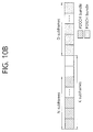
- a BS may transmit the PDCCH bundle in which an identical PDCCH is repeated on a plurality of (e.g., N) subframes for an MTC device located in a coverage extension region. Further, the BS may transmit the PDSCH bundle in which an identical PDSCH is repeated on a plurality of (e.g., D) subframes.
- the PDSCH bundle may be transmitted with a specific gap, i.e., G subframes later, after transmission of the PDCCH bundle is complete. That is, for example, if the PDCCH bundle transmission is complete on a subframe N-1, the PDSCH bundle may be transmitted on D subframes starting from a subframe N+G.
- the subframe position at which PDCCH bundle transmission starts may not be flexible as in the conventional case, and the PDCCH bundle transmission may start at a pre-agreed subframe position.
- the subframe position at which the PDCCH bundle transmission starts may be defined as a fixed value.
- the fixed value may be known to the MTC device through system information, for example, a master information block (MIB).
- MIB master information block
- the value N may be reported to the MTC device through the MIB.
- the value N may be reported to the MTC device through the MIB.
- PDCCH transmission for the MTC device located in the coverage extension region may start only through a subframe or SFN position corresponding to a multiple of 100 (e.g., 0, 100, 200, 300, ).
- the MTC device may attempt to receive the PDCCH through N subframes starting from the subframe or SFN location corresponding to the multiple of 100.
- the subframe position at which the PDCCH bundle transmission can start may vary depending on each MTC device. In this case, information on the subframe position at which the PDCCH bundle transmission can start may be known to the MTC device through a higher layer signal such as RRC.
- Subframes in which the PDCCH bundle or the PDSCH bundle are transmitted may be consecutive or non-consecutive to each other. In this case, it may be assumed that an MTC device knows at which subframe the bundling is achieved. In addition, although the number of subframes in which the PDCCH bundle or the PDSCH bundle is transmitted or a repetition number in the bundle may be set differently according to a coverage extension level required by the MTC device, it is assumed that the MTC device may know it through an SIB or other signals.
- a position of a subframe which can be used by the MTC device to receive the PDCCH bundle and the PDSCH bundle may be pre-defined or may be configured semi-statically.
- the MTC device may know the position of the subframe which can be used to receive the PDCCH bundle and the PDSCH bundle through an SIB or an RRC signal.
- FIG. 11 illustrates an example of changing a subframe pattern capable of transmitting a PDCCH bundle.
- a pattern of a subframe in which a PDCCH bundle and a PDSCH bundle can be received may be applied starting from a specific time, and may be used until a new subframe pattern is applied.
- the pattern of the subframe may be known to an MTC device through a DCI in a PDCCH.
- a time at which the MTC device applies the pattern to the new subframe may be various as follows.
- the MTC device may apply a subframe pattern acquired from a corresponding PDCCH starting from a subframe D+1.
- the MTC device may apply the subframe pattern acquired from the corresponding PDCCH starting from a subframe D+k (k >0).
- the method of applying the pattern of the subframe which can receive the PDCCH bundle and the PDSCH bundle may be used for multiplexing of a control channel/data channel. For example, a collision in PDCCH bundle transmission or PDSCH bundle transmission performed between MTC devices can be reduced by reporting a different subframe pattern to each MTC device. For another example, in PDCCH bundle transmission, bundle transmission subframe resources of several PDCCHs can be divided by reporting a different subframe pattern to the MTC device for each aggregation level or repetition level.
- the position of the subframe in which the PDCCH bundle and the PDSCH bundle can be transmitted may be set differently for each MTC device, and this may be reported to the MTC device, for example, through an RRC signal.
- the position of the subframe in which the PDCCH bundle and the PDSCH bundle can be transmitted may be reported to the MTC device by being set in unit of a specific time duration (a specific subframe duration or a specific radio frame duration). For example, if the position of the subframe in which the PDCCH bundle and the PDSCH bundle can be transmitted is reported in unit of 10 subframes, the position of the subframe is repetitively applied in every 10 subframes.
- a PDCCH repetition number (or level) in a PDCCH bundle may vary depending on which PDSCH is scheduled by the PDCCH or which RNTI is used in scrambling by the PDCCH.
- the PDCCH may be transmitted only one subframe, instead of being repeated on a plurality of subframes.
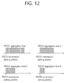
- a corresponding PDCCH repetition number that is, the number of subframes in which the PDCCH is transmitted, may be as follows.
- transmission may be achieved with a greater repetition number when a PDCCH uses a lower aggregation level.
- FIG. 13 illustrates an example in which a transmission start position varies depending on a PDCCH repetition number.
- a position of a subframe in which transmission of a PDCCH bundle and a PDSCH bundle starts can be determined in a simpler manner. This will be described below with reference to FIG. 14 .
- FIG. 14 illustrates an example of a position of a subframe in which transmission of each of a PDCCH bundle and a PDSCH bundle starts.
- a period (or interval) between subframes in which PDCCH bundle transmission can start may be equal to a period (or interval) between subframes in which PDSCH bundle transmission can start.
- the period/position of the default subframe may be used in the following situation.
- the period and/or offset value (or subframe position/pattern) of the subframe in which transmission of the PDCCH bundle on the CSS and/or the USS starts may be set differently for each MTC device, and corresponding values may differ for each C-RNTI value of the MTC device.
- the offset value for indicating the position of the subframe in which transmission of the PDCCH bundle starts may vary depending on the C-RNTI value of the MTC device. For example, if the period of the subframe in which transmission of the PDCCH bundle starts is P, the offset value may be set to (C-RNTI* ⁇ )mod P.
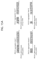
- FIG. 15a illustrates an example in which a PDSCH bundle transmission starting position is identical irrespective of a real PDCCH transmission number.
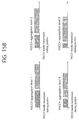
- FIG. 15b illustrates an example in which a PDSCH bundle transmission starting position varies depending on a real PDCCH transmission number.
- a PDSCH bundle transmission starting subframe position may be identical irrespective of the real PDCCH transmission number. That is, a difference between a PDCCH bundle transmission starting subframe position and the PDSCH bundle transmission starting subframe position may be identical irrespective of the real PDCCH transmission number.
- a PDCCH repetition number (i.e., repetition level, subframe number) may be less by 1/N-fold.
- the PDCCH bundle may be repetitively transmitted through D subframes, whereas if the aggregation level is 2, the PDCCH bundle may be repetitively transmitted through D/2 subframes.
- the PDCCH bundle may be transmitted through D/4 subframes and D/8 subframes, respectively.
- a PDCCH bundle and a PDSCH bundle may be transmitted in a different configuration according to a PDCCH aggregation level in one 'PDCCH repetition level'. This will be described below in detail with reference to FIG. 16 .
- FIG. 16 illustrates an example in which PDCCH bundle transmission is changed variously according to an aggregation level.
- a PDCCH repetition number is N when the aggregation level is 1 and if the PDCCH repetition number is N/2 when the aggregation level is 2, a PDCCH bundle with the aggregation level 1 may be transmitted across N consecutive subframes, and a PDCCH bundle with the aggregation level 2 may be transmitted only through a 'subframe n' for which a value of 'n mod 2' is 0 or 'subframes n' for which the value of 'n mod 2' is 1 among the N subframes.
- the following transmission method can be used to avoid a PDCCH bundle transmission resource collision of an MTC device in the presence of several MTC devices and to distribute positions of subframes in which the PDCCH bundle is transmitted.
- a subframe position at which real PDCCH bundle transmission starts may vary with an offset.
- the offset value may vary depending on the MTC device.
- the offset value may vary depending on an ID of the MTC device.
- FIG. 17 illustrates an example in which a PDCCH bundle transmission starting subframe position varies for each MTC device.
- an MTC device#1 may receive a PDCCH bundle through subframes for which a value of 'n mod 4' is 0 starting from a subframe 0, and an MTC device#2 may receive a PDCCH bundle through subframes for which a value of 'n mod 4' is 1 starting from a subframe 1.
- a subframe offset value to be used by the MTC device may vary depending on an ID of the MTC device. For example, an offset value to be used by a specific MTC device may be the same as 'MTC device ID mod M'.
- an offset value for determining a PDCCH bundle reception starting position may be determined according to a function using one or more of an ID of an MTC device, a PDCCH aggregation level, and a radio frame number. This is to evenly distribute positions of subframes in which MTC device-specific PDCCH bundle reception starts.
- FIG. 17 it is shown in FIG. 17 that PDCCH bundles for different MTC devices are distributed to different subframe regions.
- a plurality of subframe regions may be used for one MTC device.
- a search space of an MTC device is not a part of the subframe region but an entirety of the subframe region, one PDCCH bundle may be constructed of the part of the subframe region.
- a PDCCH bundle and a PDSCH bundle may be transmitted in a different configuration according to a PDCCH aggregation level in one 'PDCCH repetition level'. This will be described below with reference to FIG. 18 .
- FIG. 18 illustrates an example in which a region of subframes in which a PDCCH bundle can be transmitted varies depending on a PDCCH aggregation level.
- a PDCCH bundle is basically transmitted through consecutive subframes, while a position (or offset value) of a PDCCH bundle transmission starting subframe may vary depending on a PDCCH aggregation level. That is, when PDCCH bundles are transmitted to several MTC devices, each PDCCH bundle may have a transmission starting position which varies depending on an offset value for a specific subframe position.
- the offset value may vary depending on an aggregation level and/or an MTC device ID. As shown in FIG.
- a plurality of regions such as PDCCHs 1, 2, 3, and 4 may be present as a position of a subframe in which a PDCCH bundle can be transmitted, and a position of a subframe in which transmission of the PDCCH bundle can start may be distributed according to an offset.
- the offset value may differ for each MTC device.
- a range/candidate/set of the offset value may vary depending on the aggregation level.
- the number of regions in which the PDCCH bundle can be received may vary depending on an PDCCH aggregation level.
- a BS may select a specific region among a plurality of subframe regions.
- a subframe position at which real transmission can start may differ for each MTC device in not only PDCCH bundle but also PDSCH bundle or PUSCH bundle transmission. That is, the subframe position at which real transmission can start may vary depending on an offset value for a specific subframe position.
- the offset value may vary depending on an MTC device.
- the offset value may vary depending on an ID of the MTC device. More specifically, the offset value may be a value determined according to a function of'MTC device ID' and/or 'radio frame number'. This is to evenly distribute positions of subframes in which an MTC device-specific PDSCH bundle/PUSCH bundle is transmitted.
- a PDSCH transmission position may vary depending on a PDCCH transmission position. This will be described below with reference to FIG. 19 .
- PDSCH bundle transmission starts from a 'subframe K'
- PDSCH bundle transmission may start from a 'subframe K + offset'.
- an offset size may be equal to a PDSCH transmission subframe number.
- a period between subframes in which PDCCH transmission can start may be 2P.
- a period of a subframe in which PDCCH bundle transmission using a specific aggregation level can start may be two times a period of subframes in which PDCCH bundle transmission using an aggregation level which is two times the specific aggregation level can start.
- a start position of a CCE resource/CCE resources may be kept the same during a time of transmitting a PDCCH bundle 1 (every subframe in which the PDCCH bundle 1 is transmitted).
- the start position of the CCE resource/CCE resources may be kept the same during a time of transmitting a PDCCH bundle 2 (i.e., every subframe in which the PDCCH bundle 2 is transmitted).
- a value Y k which is a parameter for configuring a CCE resource constituting a PDCCH candidate may be allowed to be the same in a plurality of subframes in which one PDCCH bundle is transmitted. This is to avoid a collision of a CCE resource for transmission of a PDCCH candidate of different MTC devices during a PDCCH bundle transmission subframe and a collision of a USS resource and a CSS resource of the MTC device.
- this is to prevent the CSS for the MTC device located in the coverage extension region from colliding with a USS for the MTC device not located in the coverage extension region when it is assumed that a CSS for an MTC device not located in a coverage extension region is configured separately from the CSS for the MTC device located in the coverage extension region. Further, this is to prevent a collision of a CCE resource for PDCCH transmission achieved for different MTC UEs (a collision during a PDCCH bundle is transmitted).
- the PDCCH bundle transmission starting subframe index implies an index which is set to corresponding subframes, for example, in the presence of subframes in which PDCCH bundle transmission can start according to a specific period. Therefore, even for the same MTC device, the resource position of the PDCCH candidate / the starting position of resources / the CCE resource / the starting position of CCE resources may vary depending on the PDCCH bundle transmission starting position.
- the resource position of the PDCCH candidate / the starting position of resources / the CCE resource / the starting position of CCE resources may be determined in a cell-specific manner (i.e., differently for each cell). That is, Y -1 may be a value determined according to a cell ID.
- the resource position of the PDCCH candidate / the starting position of resources / the CCE resource / the starting position of CCE resources may not be changed for each subframe but be kept the same value during a specific duration (e.g., a PDCCH transmission duration, a system frame duration).
- a specific duration e.g., a PDCCH transmission duration, a system frame duration.
- the MTC device may assume that the resource position of the PDCCH candidate / the starting position of resources / the CCE resource / the starting position of CCE resources are not changed during a PDCCH bundle reception duration.
- a PDCCH of which an offset value is 1 is transmitted through subframes, i.e., a subframe n+1, a subframe n+5, a subframe n+9, ..., and the value Y k for determining the search space may also have the same value in corresponding subframes.
- a value Y -1 may vary with a specific pattern (e.g., a cell-specific pattern) according to a time (e.g., according to a radio frame).
- the value Y k may be a value which varies with a specific pattern (e.g., a cell-specific pattern) according to a time (e.g., according to a radio frame). In this case, it may be assumed that the value Y k is kept the same in a subframe region in which an identical PDCCH bundle is transmitted.
- the present specification proposes to restrict a CCE resource which can be used by the MTC device. That is, CCEs constituting a PDCCH candidate m for the MTC device may be restricted to be configured of only CCEs within a specific range.
- the present specification proposes to distinguish a PDCCH transmission resource for each PDCCH aggregation level in one subframe, in order to avoid a collision of the PDCCH transmission resource between MTC devices having different aggregation levels in one subframe.
- a value Y k for determining a CCE resource of a PDCCH candidate may be allowed to have a different value according to an aggregation level.
- a set of a value for the value Y k for determining the CCE resource of the PDCCH candidate may be allowed to be different for each aggregation level.
- FIG. 23a it is proposed that the CCE constituting the candidate m is used differently according to the PDCCH aggregation level.
- a set of a CCE index capable of constituting the candidate m is applied differently according to the PDCCH aggregation level. This will be described below with reference to FIG. 23 and FIG. 24 .
- FIG. 23a and FIG. 23b illustrate examples in which a set of a CCE index of a candidate m is determined differently according to a PDCCH aggregation level.
- a search space/PDCCH candidate resource/CCE resource used to transmit a PDCCH in one subframe may be identified according to a PDCCH aggregation level.
- the search space/PDCCH candidate resource/CCE resource used to transmit the PDCCH based on the aggregation level may differ for each MTC as shown in the example of FIG. 23b .
- the present specification proposes to divide a subframe transmitted for each aggregation level so that the CCE resource of the search space does not overlap for each aggregation level.
- an EPDCCH set on which the EPDCCH can be transmitted for each aggregation level of the EPDCCH may be identified.
- some EPDCCH aggregation levels may be transmitted only on an EPDCCH set 1, and some EPDCCH aggregation levels may be transmitted only on an EPDCCH set 2.
- FIG. 24 is a block diagram of a wireless communication system according to a disclosure of the present specification.
Landscapes
- Engineering & Computer Science (AREA)
- Signal Processing (AREA)
- Computer Networks & Wireless Communication (AREA)
- Mobile Radio Communication Systems (AREA)
Applications Claiming Priority (6)
| Application Number | Priority Date | Filing Date | Title |
|---|---|---|---|
| US201361907400P | 2013-11-22 | 2013-11-22 | |
| US201361910130P | 2013-11-29 | 2013-11-29 | |
| US201361914359P | 2013-12-10 | 2013-12-10 | |
| US201461930483P | 2014-01-23 | 2014-01-23 | |
| US201461932809P | 2014-01-29 | 2014-01-29 | |
| PCT/KR2014/011277 WO2015076619A1 (fr) | 2013-11-22 | 2014-11-21 | Procédé de réception d'un groupe de pdcch, et dispositif de mtc |
Publications (3)
| Publication Number | Publication Date |
|---|---|
| EP3073658A1 true EP3073658A1 (fr) | 2016-09-28 |
| EP3073658A4 EP3073658A4 (fr) | 2017-07-19 |
| EP3073658B1 EP3073658B1 (fr) | 2019-11-06 |
Family
ID=53179815
Family Applications (1)
| Application Number | Title | Priority Date | Filing Date |
|---|---|---|---|
| EP14863934.7A Not-in-force EP3073658B1 (fr) | 2013-11-22 | 2014-11-21 | Procédé de réception d'un groupe de pdcch, et dispositif de mtc |
Country Status (3)
| Country | Link |
|---|---|
| US (1) | US20160242203A1 (fr) |
| EP (1) | EP3073658B1 (fr) |
| WO (1) | WO2015076619A1 (fr) |
Families Citing this family (44)
| Publication number | Priority date | Publication date | Assignee | Title |
|---|---|---|---|---|
| WO2012011239A1 (fr) * | 2010-07-21 | 2012-01-26 | パナソニック株式会社 | Dispositif de station de base, dispositif de terminal, procédé de transmission et procédé de réception |
| CN110266433B (zh) * | 2014-01-10 | 2022-06-24 | 夏普株式会社 | 物理信道配置方法以及基站和用户设备 |
| CN110601804B (zh) * | 2014-01-27 | 2022-04-12 | 太阳专利托管公司 | 通信方法和用户设备 |
| US10225698B2 (en) | 2014-07-03 | 2019-03-05 | Cisco Technology, Inc. | System and method for providing message delivery and paging to a group of users in a network environment |
| US10462699B2 (en) | 2014-09-08 | 2019-10-29 | Cisco Technology, Inc. | System and method for internet protocol version-based multiple access point name support in a network environment |
| US9717068B2 (en) | 2014-09-09 | 2017-07-25 | Cisco Technology, Inc. | System and method for supporting cell updates within a small cell cluster for idle mobility in cell paging channel mode |
| US9730156B1 (en) | 2014-11-07 | 2017-08-08 | Cisco Technology, Inc. | System and method for providing power saving mode enhancements in a network environment |
| US9699725B1 (en) | 2014-11-07 | 2017-07-04 | Cisco Technology, Inc. | System and method for providing power saving mode enhancements in a network environment |
| US9843687B2 (en) | 2014-11-09 | 2017-12-12 | Cisco Technology, Inc. | System and method for radio aware traffic management based wireless authorization |
| US9629042B2 (en) | 2014-12-05 | 2017-04-18 | Cisco Technology, Inc. | System and method for providing collaborative neighbor management in a network environment |
| US9686798B1 (en) * | 2015-01-14 | 2017-06-20 | Cisco Technology, Inc. | System and method for providing collision-avoided physical downlink control channel resource allocation in a network environment |
| EP3244652A4 (fr) * | 2015-01-29 | 2018-01-17 | Huawei Technologies Co., Ltd. | Procédé d'envoi et de réception de canal et dispositif |
| US9621362B2 (en) | 2015-02-03 | 2017-04-11 | Cisco Technology, Inc. | System and method for providing policy charging and rules function discovery in a network environment |
| RU2678335C1 (ru) | 2015-02-06 | 2019-01-28 | Панасоник Интеллекчуал Проперти Корпорэйшн оф Америка | СПОСОБ БЕСПРОВОДНОЙ СВЯЗИ, eNodeB, И ОБОРУДОВАНИЕ ПОЛЬЗОВАТЕЛЯ |
| US10111216B2 (en) * | 2015-04-02 | 2018-10-23 | Qualcomm Incorporated | Reducing blind decoding in enhanced carrier aggregation |
| GB2537181A (en) | 2015-04-10 | 2016-10-12 | Nec Corp | Communication system |
| US10292176B2 (en) | 2015-07-16 | 2019-05-14 | Qualcomm Incorporated | Subframe availability for machine type communications (MTC) |
| WO2017075833A1 (fr) * | 2015-11-06 | 2017-05-11 | 华为技术有限公司 | Procédé de transmission d'informations, terminal, et station de base |
| JP2019054307A (ja) * | 2016-01-26 | 2019-04-04 | シャープ株式会社 | 基地局装置、端末装置および通信方法 |
| US20170318620A1 (en) | 2016-04-28 | 2017-11-02 | Mediatek Inc. | Connected Mode Discontinuous Reception for Narrow Band Internet of Things |
| US11025319B2 (en) * | 2016-05-10 | 2021-06-01 | Lg Electronics Inc. | Method for transmitting/receiving data signal between base station and terminal in wireless communication system and apparatus supporting same |
| US10917875B2 (en) * | 2016-06-06 | 2021-02-09 | Qualcomm Incorporated | Multicast and/or broadcast for enhanced machine type communications and/or narrowband internet-of-things |
| CN107733576A (zh) * | 2016-08-11 | 2018-02-23 | 株式会社Ntt都科摩 | 发送混合自动重复请求反馈信息的方法和用户设备 |
| JP6665351B2 (ja) * | 2016-11-02 | 2020-03-13 | テレフオンアクチーボラゲット エルエム エリクソン(パブル) | 無線通信ネットワークにおけるサーチスペースの監視 |
| PT3544347T (pt) * | 2016-12-19 | 2021-03-16 | Guangdong Oppo Mobile Telecommunications Corp Ltd | Método de transmissão de informações, dispositivo de rede e dispositivo terminal |
| US10225818B2 (en) * | 2017-02-22 | 2019-03-05 | Qualcomm Incorporated | Paging user equipments on a shared communication medium |
| WO2018187242A1 (fr) * | 2017-04-05 | 2018-10-11 | Intel IP Corporation | Taille de groupage reg et modèle dm-rs destiné à un canal de commande de liaison descendante physique |
| CN108811052B (zh) * | 2017-04-28 | 2021-05-14 | 电信科学技术研究院 | 一种下行控制信道检测接收方法、终端和网络侧设备 |
| EP3480977B1 (fr) | 2017-05-03 | 2022-07-06 | LG Electronics Inc. | Procédé d'émission ou de réception de signal dans un système de communication sans fil et appareil associé |
| US11799600B2 (en) * | 2017-05-03 | 2023-10-24 | Interdigital Patent Holdings, Inc. | Beam-based PDCCH transmission in NR |
| JP6878603B2 (ja) | 2017-06-09 | 2021-05-26 | エルジー エレクトロニクス インコーポレイティド | 無線通信システムにおいて下りリンク信号を受信又は送信する方法及びそのための装置 |
| US20210336680A1 (en) * | 2017-06-26 | 2021-10-28 | Nokia Technologies Oy | Physical Uplink Control Channel Power Control for Beam Diversity |
| US11025403B2 (en) | 2017-07-12 | 2021-06-01 | Qualcomm Incorporated | Frame structure dependent configuration of physical channels |
| KR102573235B1 (ko) * | 2017-08-11 | 2023-09-01 | 한국전자통신연구원 | 하향링크 제어 채널의 송수신 방법 및 이를 이용하는 장치 |
| US10812241B2 (en) * | 2017-09-11 | 2020-10-20 | Qualcomm Incorporated | Techniques and apparatuses for HARQ-ACK timeline indication and HARQ-ACK multiplexing and bundling in new radio |
| JP7007399B2 (ja) * | 2017-11-16 | 2022-01-24 | 株式会社Nttドコモ | 端末、無線通信方法、基地局及びシステム |
| EP3738237A1 (fr) | 2018-01-10 | 2020-11-18 | IDAC Holdings, Inc. | Procédés d'identification de ressources d'un nouveau canal physique de commande sur la liaison descendante radioélectrique ayant été préemptées par une communication à faible latence ultra-fiable |
| US11395277B2 (en) | 2018-01-12 | 2022-07-19 | Qualcomm Incorporated | Control channel mapping within search space for wireless systems |
| WO2019143164A1 (fr) * | 2018-01-21 | 2019-07-25 | 엘지전자 주식회사 | Procédé d'émission ou de réception de signal dans un système de communication sans fil et appareil à cet effet |
| CN110475345B (zh) * | 2018-05-10 | 2024-06-21 | 中兴通讯股份有限公司 | 数据传输的发送、接收方法及装置 |
| WO2020033647A1 (fr) | 2018-08-08 | 2020-02-13 | Idac Holdings, Inc. | Amélioration de fiabilité dans une communication de liaison descendante |
| EP3726904B1 (fr) * | 2018-08-10 | 2023-02-15 | LG Electronics Inc. | Procédé pour l'exécution d'une estimation de canal dans un système de communications sans fil, et appareil associé |
| US11251995B2 (en) | 2018-08-10 | 2022-02-15 | Lg Electronics Inc. | Method for performing channel estimation in wireless communication system and apparatus therefor |
| US12219579B2 (en) | 2020-02-07 | 2025-02-04 | Lg Electronics Inc. | Method and device for transmitting/receiving downlink control information in wireless communication system |
Family Cites Families (12)
| Publication number | Priority date | Publication date | Assignee | Title |
|---|---|---|---|---|
| JP2554677B2 (ja) * | 1987-11-17 | 1996-11-13 | 株式会社東芝 | 複合サイクル発電プラント |
| JPH01135021A (ja) * | 1987-11-20 | 1989-05-26 | Hitachi Ltd | 縮小投影露光装置 |
| US9131468B2 (en) * | 2011-11-08 | 2015-09-08 | Industrial Technology Research Institute | Method of handling resource allocation for MTC and related communication device |
| US9078253B2 (en) * | 2011-11-28 | 2015-07-07 | Samsung Electronics Co., Ltd. | Apparatus and method for machine-type communications |
| US9143984B2 (en) * | 2012-04-13 | 2015-09-22 | Intel Corporation | Mapping of enhanced physical downlink control channels in a wireless communication network |
| US9167585B2 (en) * | 2012-05-21 | 2015-10-20 | Samsung Electronics Co., Ltd. | Transmission mode and feedback designs to support MTC type devices in LTE |
| US9635644B2 (en) * | 2012-08-10 | 2017-04-25 | Qualcomm Incorporated | Downlink coverage enhancements |
| CN109327822B (zh) * | 2012-10-05 | 2022-10-25 | 交互数字专利控股公司 | 增强机器类型通信(mtc)设备覆盖的方法和装置 |
| KR102127393B1 (ko) * | 2013-01-14 | 2020-06-26 | 엘지전자 주식회사 | 하향링크 신호 수신 방법 및 사용자기기와 하향링크 신호 전송 방법 및 기지국 |
| CN104348580A (zh) * | 2013-08-06 | 2015-02-11 | 夏普株式会社 | 下行物理信道的发送和接收方法以及基站和用户设备 |
| WO2015046808A1 (fr) * | 2013-09-27 | 2015-04-02 | 주식회사 케이티 | Procédé d'amélioration du taux de réception d'un canal de commande en liaison descendante dans un terminal, et appareil associé |
| KR101919636B1 (ko) * | 2013-10-04 | 2018-11-20 | 주식회사 케이티 | 하향링크 제어 채널을 송수신하는 방법 및 그 장치 |
-
2014
- 2014-11-21 US US15/026,570 patent/US20160242203A1/en not_active Abandoned
- 2014-11-21 WO PCT/KR2014/011277 patent/WO2015076619A1/fr not_active Ceased
- 2014-11-21 EP EP14863934.7A patent/EP3073658B1/fr not_active Not-in-force
Also Published As
| Publication number | Publication date |
|---|---|
| EP3073658B1 (fr) | 2019-11-06 |
| EP3073658A4 (fr) | 2017-07-19 |
| WO2015076619A1 (fr) | 2015-05-28 |
| US20160242203A1 (en) | 2016-08-18 |
Similar Documents
| Publication | Publication Date | Title |
|---|---|---|
| EP3073658B1 (fr) | Procédé de réception d'un groupe de pdcch, et dispositif de mtc | |
| US10623967B2 (en) | Method and MTC device for performing random access procedure for coverage enhancement | |
| EP3086491B1 (fr) | Procédé et terminal pour recevoir un regroupement d'epdcch | |
| US10863320B2 (en) | Transmission/reception method for MTC apparatus | |
| US10560873B2 (en) | Reception method of MTC device | |
| US9923674B2 (en) | Method for transmitting and receiving uplink/downlink data with MTC device | |
| KR102058718B1 (ko) | 상향링크 제어 채널 전송 방법 및 이를 수행하는 사용자 장치 | |
| EP3091674B1 (fr) | Procédé et dispositif mtc d'exécution d'une procédure d'accès aléatoire conformément à une pluralité d'ensembles de paramètres | |
| US10159090B2 (en) | Method for transmitting, to MTC device, PDSCH including downlink data, and base station therefor | |
| EP3291474A1 (fr) | Procédé et appareil lc pour réception de canal de commande en liaison descendante | |
| EP3113388A1 (fr) | Procédé de surveillance d'un pdcch dans une communication semi-duplex en fdd et terminal associé | |
| EP3116156A1 (fr) | Procédé et appareil pour transmettre un canal de commande de liaison montante dans un système de communication sans fil | |
| EP2996296A1 (fr) | Procédé de communication prenant en considération le type de porteuse et appareil associé | |
| EP3300287B1 (fr) | Dispositif sans fil et procédé de réception de canal de commande de liaison descendante | |
| US10827505B2 (en) | Method for receiving downlink control channel by MTC device, and terminal | |
| EP3979548A1 (fr) | Procédé et dispositif d'émission ou de réception d'un signal sans fil dans un système de communication sans fil | |
| US11284383B2 (en) | Transmission/reception method for MTC apparatus |
Legal Events
| Date | Code | Title | Description |
|---|---|---|---|
| PUAI | Public reference made under article 153(3) epc to a published international application that has entered the european phase |
Free format text: ORIGINAL CODE: 0009012 |
|
| 17P | Request for examination filed |
Effective date: 20160412 |
|
| AK | Designated contracting states |
Kind code of ref document: A1 Designated state(s): AL AT BE BG CH CY CZ DE DK EE ES FI FR GB GR HR HU IE IS IT LI LT LU LV MC MK MT NL NO PL PT RO RS SE SI SK SM TR |
|
| AX | Request for extension of the european patent |
Extension state: BA ME |
|
| DAX | Request for extension of the european patent (deleted) | ||
| A4 | Supplementary search report drawn up and despatched |
Effective date: 20170616 |
|
| RIC1 | Information provided on ipc code assigned before grant |
Ipc: H04W 4/00 20090101ALI20170609BHEP Ipc: H04L 5/00 20060101ALI20170609BHEP Ipc: H04B 7/26 20060101ALI20170609BHEP Ipc: H04L 27/26 20060101ALI20170609BHEP Ipc: H04J 11/00 20060101AFI20170609BHEP |
|
| STAA | Information on the status of an ep patent application or granted ep patent |
Free format text: STATUS: EXAMINATION IS IN PROGRESS |
|
| 17Q | First examination report despatched |
Effective date: 20180912 |
|
| REG | Reference to a national code |
Ref country code: DE Ref legal event code: R079 Ref document number: 602014056542 Country of ref document: DE Free format text: PREVIOUS MAIN CLASS: H04J0011000000 Ipc: H04L0005000000 |
|
| GRAP | Despatch of communication of intention to grant a patent |
Free format text: ORIGINAL CODE: EPIDOSNIGR1 |
|
| STAA | Information on the status of an ep patent application or granted ep patent |
Free format text: STATUS: GRANT OF PATENT IS INTENDED |
|
| RIC1 | Information provided on ipc code assigned before grant |
Ipc: H04W 4/70 20180101ALI20190621BHEP Ipc: H04L 27/26 20060101ALI20190621BHEP Ipc: H04L 5/00 20060101AFI20190621BHEP |
|
| INTG | Intention to grant announced |
Effective date: 20190710 |
|
| GRAS | Grant fee paid |
Free format text: ORIGINAL CODE: EPIDOSNIGR3 |
|
| GRAA | (expected) grant |
Free format text: ORIGINAL CODE: 0009210 |
|
| STAA | Information on the status of an ep patent application or granted ep patent |
Free format text: STATUS: THE PATENT HAS BEEN GRANTED |
|
| AK | Designated contracting states |
Kind code of ref document: B1 Designated state(s): AL AT BE BG CH CY CZ DE DK EE ES FI FR GB GR HR HU IE IS IT LI LT LU LV MC MK MT NL NO PL PT RO RS SE SI SK SM TR |
|
| REG | Reference to a national code |
Ref country code: GB Ref legal event code: FG4D |
|
| REG | Reference to a national code |
Ref country code: CH Ref legal event code: EP Ref country code: AT Ref legal event code: REF Ref document number: 1200268 Country of ref document: AT Kind code of ref document: T Effective date: 20191115 |
|
| REG | Reference to a national code |
Ref country code: IE Ref legal event code: FG4D |
|
| REG | Reference to a national code |
Ref country code: DE Ref legal event code: R096 Ref document number: 602014056542 Country of ref document: DE |
|
| PGFP | Annual fee paid to national office [announced via postgrant information from national office to epo] |
Ref country code: DE Payment date: 20191128 Year of fee payment: 6 |
|
| REG | Reference to a national code |
Ref country code: NL Ref legal event code: MP Effective date: 20191106 |
|
| REG | Reference to a national code |
Ref country code: LT Ref legal event code: MG4D |
|
| PG25 | Lapsed in a contracting state [announced via postgrant information from national office to epo] |
Ref country code: LV Free format text: LAPSE BECAUSE OF FAILURE TO SUBMIT A TRANSLATION OF THE DESCRIPTION OR TO PAY THE FEE WITHIN THE PRESCRIBED TIME-LIMIT Effective date: 20191106 Ref country code: SE Free format text: LAPSE BECAUSE OF FAILURE TO SUBMIT A TRANSLATION OF THE DESCRIPTION OR TO PAY THE FEE WITHIN THE PRESCRIBED TIME-LIMIT Effective date: 20191106 Ref country code: PT Free format text: LAPSE BECAUSE OF FAILURE TO SUBMIT A TRANSLATION OF THE DESCRIPTION OR TO PAY THE FEE WITHIN THE PRESCRIBED TIME-LIMIT Effective date: 20200306 Ref country code: PL Free format text: LAPSE BECAUSE OF FAILURE TO SUBMIT A TRANSLATION OF THE DESCRIPTION OR TO PAY THE FEE WITHIN THE PRESCRIBED TIME-LIMIT Effective date: 20191106 Ref country code: NL Free format text: LAPSE BECAUSE OF FAILURE TO SUBMIT A TRANSLATION OF THE DESCRIPTION OR TO PAY THE FEE WITHIN THE PRESCRIBED TIME-LIMIT Effective date: 20191106 Ref country code: LT Free format text: LAPSE BECAUSE OF FAILURE TO SUBMIT A TRANSLATION OF THE DESCRIPTION OR TO PAY THE FEE WITHIN THE PRESCRIBED TIME-LIMIT Effective date: 20191106 Ref country code: FI Free format text: LAPSE BECAUSE OF FAILURE TO SUBMIT A TRANSLATION OF THE DESCRIPTION OR TO PAY THE FEE WITHIN THE PRESCRIBED TIME-LIMIT Effective date: 20191106 Ref country code: BG Free format text: LAPSE BECAUSE OF FAILURE TO SUBMIT A TRANSLATION OF THE DESCRIPTION OR TO PAY THE FEE WITHIN THE PRESCRIBED TIME-LIMIT Effective date: 20200206 Ref country code: NO Free format text: LAPSE BECAUSE OF FAILURE TO SUBMIT A TRANSLATION OF THE DESCRIPTION OR TO PAY THE FEE WITHIN THE PRESCRIBED TIME-LIMIT Effective date: 20200206 Ref country code: GR Free format text: LAPSE BECAUSE OF FAILURE TO SUBMIT A TRANSLATION OF THE DESCRIPTION OR TO PAY THE FEE WITHIN THE PRESCRIBED TIME-LIMIT Effective date: 20200207 |
|
| PG25 | Lapsed in a contracting state [announced via postgrant information from national office to epo] |
Ref country code: RS Free format text: LAPSE BECAUSE OF FAILURE TO SUBMIT A TRANSLATION OF THE DESCRIPTION OR TO PAY THE FEE WITHIN THE PRESCRIBED TIME-LIMIT Effective date: 20191106 Ref country code: IS Free format text: LAPSE BECAUSE OF FAILURE TO SUBMIT A TRANSLATION OF THE DESCRIPTION OR TO PAY THE FEE WITHIN THE PRESCRIBED TIME-LIMIT Effective date: 20200306 Ref country code: HR Free format text: LAPSE BECAUSE OF FAILURE TO SUBMIT A TRANSLATION OF THE DESCRIPTION OR TO PAY THE FEE WITHIN THE PRESCRIBED TIME-LIMIT Effective date: 20191106 |
|
| PG25 | Lapsed in a contracting state [announced via postgrant information from national office to epo] |
Ref country code: AL Free format text: LAPSE BECAUSE OF FAILURE TO SUBMIT A TRANSLATION OF THE DESCRIPTION OR TO PAY THE FEE WITHIN THE PRESCRIBED TIME-LIMIT Effective date: 20191106 |
|
| REG | Reference to a national code |
Ref country code: CH Ref legal event code: PL |
|
| PG25 | Lapsed in a contracting state [announced via postgrant information from national office to epo] |
Ref country code: EE Free format text: LAPSE BECAUSE OF FAILURE TO SUBMIT A TRANSLATION OF THE DESCRIPTION OR TO PAY THE FEE WITHIN THE PRESCRIBED TIME-LIMIT Effective date: 20191106 Ref country code: LI Free format text: LAPSE BECAUSE OF NON-PAYMENT OF DUE FEES Effective date: 20191130 Ref country code: DK Free format text: LAPSE BECAUSE OF FAILURE TO SUBMIT A TRANSLATION OF THE DESCRIPTION OR TO PAY THE FEE WITHIN THE PRESCRIBED TIME-LIMIT Effective date: 20191106 Ref country code: CH Free format text: LAPSE BECAUSE OF NON-PAYMENT OF DUE FEES Effective date: 20191130 Ref country code: ES Free format text: LAPSE BECAUSE OF FAILURE TO SUBMIT A TRANSLATION OF THE DESCRIPTION OR TO PAY THE FEE WITHIN THE PRESCRIBED TIME-LIMIT Effective date: 20191106 Ref country code: LU Free format text: LAPSE BECAUSE OF NON-PAYMENT OF DUE FEES Effective date: 20191121 Ref country code: RO Free format text: LAPSE BECAUSE OF FAILURE TO SUBMIT A TRANSLATION OF THE DESCRIPTION OR TO PAY THE FEE WITHIN THE PRESCRIBED TIME-LIMIT Effective date: 20191106 Ref country code: CZ Free format text: LAPSE BECAUSE OF FAILURE TO SUBMIT A TRANSLATION OF THE DESCRIPTION OR TO PAY THE FEE WITHIN THE PRESCRIBED TIME-LIMIT Effective date: 20191106 |
|
| REG | Reference to a national code |
Ref country code: DE Ref legal event code: R097 Ref document number: 602014056542 Country of ref document: DE |
|
| REG | Reference to a national code |
Ref country code: AT Ref legal event code: MK05 Ref document number: 1200268 Country of ref document: AT Kind code of ref document: T Effective date: 20191106 |
|
| REG | Reference to a national code |
Ref country code: BE Ref legal event code: MM Effective date: 20191130 |
|
| PG25 | Lapsed in a contracting state [announced via postgrant information from national office to epo] |
Ref country code: SM Free format text: LAPSE BECAUSE OF FAILURE TO SUBMIT A TRANSLATION OF THE DESCRIPTION OR TO PAY THE FEE WITHIN THE PRESCRIBED TIME-LIMIT Effective date: 20191106 Ref country code: SK Free format text: LAPSE BECAUSE OF FAILURE TO SUBMIT A TRANSLATION OF THE DESCRIPTION OR TO PAY THE FEE WITHIN THE PRESCRIBED TIME-LIMIT Effective date: 20191106 Ref country code: MC Free format text: LAPSE BECAUSE OF FAILURE TO SUBMIT A TRANSLATION OF THE DESCRIPTION OR TO PAY THE FEE WITHIN THE PRESCRIBED TIME-LIMIT Effective date: 20191106 |
|
| PLBE | No opposition filed within time limit |
Free format text: ORIGINAL CODE: 0009261 |
|
| STAA | Information on the status of an ep patent application or granted ep patent |
Free format text: STATUS: NO OPPOSITION FILED WITHIN TIME LIMIT |
|
| 26N | No opposition filed |
Effective date: 20200807 |
|
| GBPC | Gb: european patent ceased through non-payment of renewal fee |
Effective date: 20200206 |
|
| PG25 | Lapsed in a contracting state [announced via postgrant information from national office to epo] |
Ref country code: FR Free format text: LAPSE BECAUSE OF NON-PAYMENT OF DUE FEES Effective date: 20200106 Ref country code: IE Free format text: LAPSE BECAUSE OF NON-PAYMENT OF DUE FEES Effective date: 20191121 |
|
| PG25 | Lapsed in a contracting state [announced via postgrant information from national office to epo] |
Ref country code: SI Free format text: LAPSE BECAUSE OF FAILURE TO SUBMIT A TRANSLATION OF THE DESCRIPTION OR TO PAY THE FEE WITHIN THE PRESCRIBED TIME-LIMIT Effective date: 20191106 Ref country code: AT Free format text: LAPSE BECAUSE OF FAILURE TO SUBMIT A TRANSLATION OF THE DESCRIPTION OR TO PAY THE FEE WITHIN THE PRESCRIBED TIME-LIMIT Effective date: 20191106 Ref country code: BE Free format text: LAPSE BECAUSE OF NON-PAYMENT OF DUE FEES Effective date: 20191130 |
|
| PG25 | Lapsed in a contracting state [announced via postgrant information from national office to epo] |
Ref country code: GB Free format text: LAPSE BECAUSE OF NON-PAYMENT OF DUE FEES Effective date: 20200206 Ref country code: IT Free format text: LAPSE BECAUSE OF FAILURE TO SUBMIT A TRANSLATION OF THE DESCRIPTION OR TO PAY THE FEE WITHIN THE PRESCRIBED TIME-LIMIT Effective date: 20191106 |
|
| PG25 | Lapsed in a contracting state [announced via postgrant information from national office to epo] |
Ref country code: CY Free format text: LAPSE BECAUSE OF FAILURE TO SUBMIT A TRANSLATION OF THE DESCRIPTION OR TO PAY THE FEE WITHIN THE PRESCRIBED TIME-LIMIT Effective date: 20191106 |
|
| REG | Reference to a national code |
Ref country code: DE Ref legal event code: R119 Ref document number: 602014056542 Country of ref document: DE |
|
| PG25 | Lapsed in a contracting state [announced via postgrant information from national office to epo] |
Ref country code: MT Free format text: LAPSE BECAUSE OF FAILURE TO SUBMIT A TRANSLATION OF THE DESCRIPTION OR TO PAY THE FEE WITHIN THE PRESCRIBED TIME-LIMIT Effective date: 20191106 Ref country code: HU Free format text: LAPSE BECAUSE OF FAILURE TO SUBMIT A TRANSLATION OF THE DESCRIPTION OR TO PAY THE FEE WITHIN THE PRESCRIBED TIME-LIMIT; INVALID AB INITIO Effective date: 20141121 |
|
| PG25 | Lapsed in a contracting state [announced via postgrant information from national office to epo] |
Ref country code: DE Free format text: LAPSE BECAUSE OF NON-PAYMENT OF DUE FEES Effective date: 20210601 |
|
| PG25 | Lapsed in a contracting state [announced via postgrant information from national office to epo] |
Ref country code: TR Free format text: LAPSE BECAUSE OF FAILURE TO SUBMIT A TRANSLATION OF THE DESCRIPTION OR TO PAY THE FEE WITHIN THE PRESCRIBED TIME-LIMIT Effective date: 20191106 |
|
| PG25 | Lapsed in a contracting state [announced via postgrant information from national office to epo] |
Ref country code: MK Free format text: LAPSE BECAUSE OF FAILURE TO SUBMIT A TRANSLATION OF THE DESCRIPTION OR TO PAY THE FEE WITHIN THE PRESCRIBED TIME-LIMIT Effective date: 20191106 |