EP3073691A1 - Procédé, dispositif et système pour améliorer la qos - Google Patents
Procédé, dispositif et système pour améliorer la qos Download PDFInfo
- Publication number
- EP3073691A1 EP3073691A1 EP13899184.9A EP13899184A EP3073691A1 EP 3073691 A1 EP3073691 A1 EP 3073691A1 EP 13899184 A EP13899184 A EP 13899184A EP 3073691 A1 EP3073691 A1 EP 3073691A1
- Authority
- EP
- European Patent Office
- Prior art keywords
- user equipment
- address
- port number
- service port
- user
- Prior art date
- Legal status (The legal status is an assumption and is not a legal conclusion. Google has not performed a legal analysis and makes no representation as to the accuracy of the status listed.)
- Granted
Links
Images




Classifications
-
- H—ELECTRICITY
- H04—ELECTRIC COMMUNICATION TECHNIQUE
- H04L—TRANSMISSION OF DIGITAL INFORMATION, e.g. TELEGRAPHIC COMMUNICATION
- H04L65/00—Network arrangements, protocols or services for supporting real-time applications in data packet communication
- H04L65/80—Responding to QoS
-
- H—ELECTRICITY
- H04—ELECTRIC COMMUNICATION TECHNIQUE
- H04L—TRANSMISSION OF DIGITAL INFORMATION, e.g. TELEGRAPHIC COMMUNICATION
- H04L12/00—Data switching networks
- H04L12/02—Details
- H04L12/14—Charging, metering or billing arrangements specially adapted for data communications, e.g. authentication, authorisation and accounting [AAA] framework
- H04L12/1403—Architecture for metering, charging or billing
- H04L12/1407—Policy-and-charging control [PCC] architecture
-
- H—ELECTRICITY
- H04—ELECTRIC COMMUNICATION TECHNIQUE
- H04L—TRANSMISSION OF DIGITAL INFORMATION, e.g. TELEGRAPHIC COMMUNICATION
- H04L41/00—Arrangements for maintenance, administration or management of data switching networks, e.g. of packet switching networks
- H04L41/50—Network service management, e.g. ensuring proper service fulfilment according to agreements
- H04L41/5003—Managing SLA; Interaction between SLA and QoS
-
- H—ELECTRICITY
- H04—ELECTRIC COMMUNICATION TECHNIQUE
- H04L—TRANSMISSION OF DIGITAL INFORMATION, e.g. TELEGRAPHIC COMMUNICATION
- H04L61/00—Network arrangements, protocols or services for addressing or naming
- H04L61/50—Address allocation
- H04L61/5007—Internet protocol [IP] addresses
-
- H—ELECTRICITY
- H04—ELECTRIC COMMUNICATION TECHNIQUE
- H04L—TRANSMISSION OF DIGITAL INFORMATION, e.g. TELEGRAPHIC COMMUNICATION
- H04L65/00—Network arrangements, protocols or services for supporting real-time applications in data packet communication
- H04L65/10—Architectures or entities
- H04L65/1016—IP multimedia subsystem [IMS]
-
- H—ELECTRICITY
- H04—ELECTRIC COMMUNICATION TECHNIQUE
- H04L—TRANSMISSION OF DIGITAL INFORMATION, e.g. TELEGRAPHIC COMMUNICATION
- H04L65/00—Network arrangements, protocols or services for supporting real-time applications in data packet communication
- H04L65/1066—Session management
- H04L65/1069—Session establishment or de-establishment
-
- H—ELECTRICITY
- H04—ELECTRIC COMMUNICATION TECHNIQUE
- H04L—TRANSMISSION OF DIGITAL INFORMATION, e.g. TELEGRAPHIC COMMUNICATION
- H04L65/00—Network arrangements, protocols or services for supporting real-time applications in data packet communication
- H04L65/60—Network streaming of media packets
- H04L65/65—Network streaming protocols, e.g. real-time transport protocol [RTP] or real-time control protocol [RTCP]
-
- H—ELECTRICITY
- H04—ELECTRIC COMMUNICATION TECHNIQUE
- H04L—TRANSMISSION OF DIGITAL INFORMATION, e.g. TELEGRAPHIC COMMUNICATION
- H04L67/00—Network arrangements or protocols for supporting network services or applications
- H04L67/01—Protocols
- H04L67/02—Protocols based on web technology, e.g. hypertext transfer protocol [HTTP]
-
- H—ELECTRICITY
- H04—ELECTRIC COMMUNICATION TECHNIQUE
- H04L—TRANSMISSION OF DIGITAL INFORMATION, e.g. TELEGRAPHIC COMMUNICATION
- H04L69/00—Network arrangements, protocols or services independent of the application payload and not provided for in the other groups of this subclass
- H04L69/30—Definitions, standards or architectural aspects of layered protocol stacks
- H04L69/32—Architecture of open systems interconnection [OSI] 7-layer type protocol stacks, e.g. the interfaces between the data link level and the physical level
- H04L69/322—Intralayer communication protocols among peer entities or protocol data unit [PDU] definitions
- H04L69/329—Intralayer communication protocols among peer entities or protocol data unit [PDU] definitions in the application layer [OSI layer 7]
Definitions
- the present invention relates to the communications field, and in particular, to a QoS improvement method, apparatus, and system.
- a web real-time communication (Web Real-Time Communication, WebRTC for short) is a technology of performing real-time video and audio communication inside a browser, and the technology is based on a Web Hypertext Application Technology Working Group (Web Hypertext Application Technology Working Group, WHATWG for short) protocol, to achieve a real-time communication (Real-Time Communication, RTC for short) capability by providing a simple Java description language by using a browser.
- An ultimate objective of a WebRTC project is mainly to enable a Web developer to easily and quickly develop, based on a browser, abundant real-time multimedia applications, and the Web developer does not need to download or install any plug-in.
- the Web developer does not need to focus on a digital signal processing process of multimedia either, but only needs to write a simple Java language program.
- a real-time communication platform can be established among multiple Internet browsers, to form a desirable ecosystem between a developer and a browser vendor.
- each WebRtc application based on a mobile terminal includes a quality of service (Quality of Service, QoS for short) improvement service, which improves QoS (for example: bandwidth) of a WebRtc application of user equipment.
- QoS Quality of Service
- the user equipment A needs to collect information about Internet Protocol (Internet Protocol, IP for short) addresses and service port numbers of the both parties in the communication, then send a service acceleration request to a QoS decision network element to improve QoS of an audio and video service of a current user, and send the collected information about the IP addresses and the service port numbers of the both parties in the communication to the QoS decision network element.
- IP Internet Protocol
- the QoS decision network element forms a parameter by using the IP addresses and the service port numbers of the both parties in the communication, and sends an acceleration request to a policy and charging rule function entity (Policy and Charging Rule Function, PCRF for short), to separately improve QoS of the user equipment A and QoS of the user equipment B, thereby improving user experience of audio and video communication performed between the user equipment A and the user equipment B.
- Policy and Charging Rule Function Policy and Charging Rule Function
- the foregoing QoS improvement process of the WebRtc audio and video communications application in the prior art has the following problems: when user equipment A and user equipment B perform audio and video communication, if the user equipment A finds that user experience of the audio and video communication with the user equipment B is relatively poor, the user equipment A requests a QoS decision network element to perform QoS improvement.
- the user equipment A can send a QoS improvement request to the QoS decision network element only after collecting information about IP addresses and service port numbers of the both parties that perform audio and video communication.
- the user equipment is responsible for collecting the IP addresses and the service port numbers of the both parties in the communication. Therefore, burden on the user equipment is relatively heavy, and difficulty in using the current QoS improvement method by a user is increased.
- Embodiments of the present invention provide a QoS improvement method, apparatus, and system, where a network side acquires IP addresses and service port numbers of both parties of user equipments in audio and video communication, to perform QoS improvement.
- a QoS improvement method including: acquiring, by a WebRtc server, an IP address and a service port number of user equipment A, and an IP address and a service port number of user equipment B; and sending, by the WebRtc server, the IP address and the service port number of the user equipment A, and the IP address and the service port number of the user equipment B to a QoS decision network element, so that the QoS decision network element forms a parameter according to the IP address and the service port number of the user equipment A, and the IP address and the service port number of the user equipment B, and sends a QoS improvement request to a PCRF.
- the method includes: the acquiring, by a WebRtc server, an IP address and a service port number of user equipment A, and an IP address and a service port number of user equipment B includes: receiving, by the WebRtc server, call request signaling sent by the user equipment A to the user equipment B, where the call request signaling includes the IP address and the service port number of the user equipment A, and acquiring the IP address and the service port number of the user equipment A from the call request signaling; sending, by the WebRtc server, the call request signaling to the user equipment B; and receiving, by the WebRtc server, answer signaling returned by the user equipment B to the user equipment A, where the answer signaling includes the IP address and the service port number of the user equipment B, and acquiring the IP address and the service port number of the user equipment A from the answer signaling.
- the method includes: binding, by the WebRtc server, the IP address and the service port number of the user equipment A, and the IP address and the service port number of the user equipment B to a user identity of the user equipment A, and a user identity of the user equipment B respectively; receiving, by the WebRtc server, request signaling sent by the QoS decision network element, and requesting to acquire the IP address and the service port number of the user equipment A, and the IP address and the service port number of the user equipment B, where the request signaling includes the user identity of the user equipment A, and the user identity of
- the sending, by the WebRtc server, the IP address and the service port number of the user equipment A, and the IP address and the service port number of the user equipment B to a QoS decision network element specifically includes: after the receiving, by the WebRtc server, call request signaling sent by the user equipment A to the user equipment B, sending, by the WebRtc server, the IP address and the service port number of the user equipment A to the QoS decision network element; and after the receiving, by the WebRtc server, answer signaling returned by the user equipment B to the user equipment A, sending, by the WebRtc server, the IP address and the service port number of the user equipment B to the QoS decision network element.
- the sending, by the WebRtc server, the IP address and the service port number of the user equipment A, and the IP address and the service port number of the user equipment B to a QoS decision network element specifically includes:
- another QoS improvement method including: acquiring, by a WebRtc server, an IP address and a service port number of user equipment A, and an IP address and a service port number of user equipment B; and receiving, by the WebRtc server, request signaling from a QoS decision network element, and requesting to acquire the service port number of the user equipment A and the service port number of the user equipment B, where the request signaling includes the IP address of the user equipment A and the IP address of the user equipment B; and acquiring, by the WebRtc server, the service port number of the user equipment A and the service port number of the user equipment B according to the IP address of the user equipment A and the IP address of the user equipment B, and sending the service port number of the user equipment A and the service port number of the user equipment B to the QoS decision network element, so that the QoS decision network element forms a parameter according to the IP address and the service port number of the user equipment A, and the IP address and the service port number of the user equipment B
- the method includes: receiving, by the WebRtc server, call request signaling sent by the user equipment A to the user equipment B, where the call request signaling includes the IP address and the service port number of the user equipment A, and acquiring the IP address and the service port number of the user equipment A from the call request signaling; sending, by the WebRtc server, the call request signaling to the user equipment B; and receiving, by the WebRtc server, answer signaling returned by the user equipment B to the user equipment A, where the answer signaling includes the IP address and the service port number of the user equipment B
- another QoS improvement method including: receiving, by a QoS decision network element, an IP address and a service port number of user equipment A, and an IP address and a service port number of user equipment B that are sent by a WebRtc server; receiving, by the QoS decision network element, a service acceleration request sent by the user equipment A, and requesting to perform QoS improvement on a service between the user equipment A and the user equipment B; and forming, by the QoS decision network element, a parameter according to the IP address and the service port number of the user equipment A, and the IP address and the service port number of the user equipment B, and sending a QoS improvement request to a PCRF.
- the service acceleration request includes a user identity of the user equipment A, and a user identity of the user equipment B
- the method further includes: sending, by the QoS decision network element, request signaling to the WebRtc server, and requesting to acquire the IP address and the service port number of the user equipment A, and the IP address and the service port number of the user equipment B, where the request signaling includes the user identity of the user equipment A, and the user identity of the user equipment B; and the receiving, by a QoS decision network element, an IP address and a service port number of user equipment A, and an IP address and a service port number of user equipment B that are sent by a WebRtc server specifically includes: receiving, by the QoS decision network element, the IP address and the service port number of the user equipment A, and the IP address and the service port number of the user equipment B that are returned by the WebRtc server according to the user identity of the user equipment A, and the user identity of the user equipment B.
- the method further includes: when the user equipment A and the user equipment B are attached, acquiring, by the QoS decision network element, a user identity of the user equipment A and a user identity of the user equipment B that are sent by a mobile network; after the receiving, by a QoS decision network element, an IP address and a service port number of user equipment A, and an IP address and a service port number of user equipment B that are sent by a WebRtc server, the method further includes: binding, by the QoS decision network element, the IP address and the service port number of the user equipment A, and the IP address and the service port number of the user equipment B to the user identity of the user equipment A, and the user identity of the user equipment B respectively; and the receiving, by the QoS decision network element, a service acceleration request sent by the user equipment A, and the forming, by the QoS decision network element, a parameter according to the IP address and the service port number of the user equipment A, and the IP address and
- another QoS improvement method including: receiving, by a QoS decision network element, an IP address of user equipment A, and an IP address of user equipment B that are sent by a mobile network; receiving, by the QoS decision network element, a service acceleration request sent by the user equipment A, and requesting to perform QoS improvement on a service between the user equipment A and the user equipment B; sending, by the QoS decision network element, request signaling to a WebRtc server, and requesting to acquire a service port number of the user equipment A, and a service port number of the user equipment B, where the request signaling includes the IP address of the user equipment A, and the IP address of the user equipment B; receiving, by the QoS decision network element, the service port number of the user equipment A, and the service port number of the user equipment B that are sent by the WebRtc server; and forming, by the QoS decision network element, a parameter according to the IP address and the service port number of the user equipment A, and the IP
- the receiving, by a QoS decision network element, an IP address of user equipment A, and an IP address of user equipment B that are sent by a mobile network includes:
- a QoS improvement apparatus including: a receiving module, configured to receive an IP address and a service port number of user equipment A, and an IP address and a service port number of user equipment B; and a sending module, configured to send the IP address and the service port number of the user equipment A, and the IP address and the service port number of the user equipment B to a QoS decision network element, so that the QoS decision network element forms a parameter according to the IP address and the service port number of the user equipment A, and the IP address and the service port number of the user equipment B, and sends a QoS improvement request to a PCRF.
- the receiving module is specifically configured to receive call request signaling sent by the user equipment A to the user equipment B, where the call request signaling includes the IP address and the service port number of the user equipment A, and acquire the IP address and the service port number of the user equipment A from the call request signaling; the sending module is further configured to send the call request signaling to the user equipment B; and the receiving module is specifically configured to receive answer signaling returned by the user equipment B to the user equipment A, where the answer signaling includes the IP address and the service port number of the user equipment B, and acquire the IP address and the service port number of the user equipment B from the answer signaling.
- the apparatus further includes: a processing module, configured to: after the receiving module receives the IP address and the service port number of the user equipment A, and the IP address and the service port number of the user equipment B, bind the received IP address and service port number of the user equipment A, and the received IP address and service port number of the user equipment B to a user identity of the user equipment A corresponding to the received IP address and service port number of the user equipment A, and a user identity of the user equipment B corresponding to the received IP address and service port number of the user equipment B respectively; the receiving module is further configured to receive request signaling sent by the QoS decision network element, and request to acquire the IP address and the service port number of the user equipment A, and the IP address and the service port number of the user equipment B, where the request signaling includes the user identity of the user equipment A, and the user identity of the user equipment B; and the sending module being configured to send the IP address and the service port
- the sending module being configured to send the IP address and the service port number of the user equipment A, and the IP address and the service port number of the user equipment B to a QoS decision network element specifically includes: the sending module being configured to: after the receiving module receives the call request signaling sent by the user equipment A to the user equipment B, send the IP address and the service port number of the user equipment A to the QoS decision network element; and after the receiving module receives the answer signaling returned by the user equipment B to the user equipment A, send the IP address and the service port number of the user equipment B to the QoS decision network element.
- the sending module being configured to send the IP address and the service port number of the user equipment A, and the IP address and the service port number of the user equipment B to a QoS decision network element specifically includes: the sending module being configured to: after the receiving module receives the answer signaling returned by the user equipment B to the user equipment A, send the IP address and the service port number of the user equipment A, and the IP address and the service port number of the user equipment B to the QoS decision network element.
- another QoS improvement apparatus including: a receiving module, configured to receive an IP address and a service port number of user equipment A, and an IP address and a service port number of user equipment B; and receive request signaling from a QoS decision network element, and request to acquire the service port number of the user equipment A, and the service port number of the user equipment B, where the request signaling includes the IP address of the user equipment A, and the IP address of the user equipment B; and a sending module, configured to: acquire the service port number of the user equipment A and the service port number of the user equipment B according to the IP address of the user equipment A and the IP address of the user equipment B, and send the service port number of the user equipment A and the service port number of the user equipment B to the QoS decision network element, so that the QoS decision network element forms a parameter according to the IP address and the service port number of the user equipment A, and the IP address and the service port number of the user equipment B, and sends a QoS improvement request to
- the receiving module is specifically configured to receive call request signaling sent by the user equipment A to the user equipment B, where the call request signaling includes the IP address and the service port number of the user equipment A, and acquire the IP address and the service port number of the user equipment A from the call request signaling; and receive answer signaling returned by the user equipment B to the user equipment A, where the answer signaling includes the IP address and the service port number of the user equipment B, and acquire the IP address and the service port number of the user equipment B from the answer signaling; and the sending module is further configured to: after the receiving module receives the call request signaling sent by the user equipment A to the user equipment B, send the call request signaling to the user equipment B.
- another QoS improvement apparatus including: a receiving module, configured to receive an IP address and a service port number of user equipment A, and an IP address and a service port number of user equipment B that are sent by a WebRtc server; and receive a service acceleration request sent by the user equipment A; and a sending module, configured to form a parameter according to the IP address and the service port number of the user equipment A, and the IP address and the service port number of the user equipment B, and send a QoS improvement request to a PCRF.
- the service acceleration request includes a user identity of the user equipment A, and a user identity of the user equipment B
- the sending apparatus is further configured to send request signaling to the WebRtc server, and request to acquire the IP address and the service port number of the user equipment A, and the IP address and the service port number of the user equipment B, where the request signaling includes the user identity of the user equipment A and the user identity of the user equipment B
- the receiving module being configured to receive an IP address and a service port number of user equipment A, and an IP address and a service port number of user equipment B that are sent by a WebRtc server specifically includes: the receiving module being configured to receive the IP address and the service port number of the user equipment A, and the IP address and the service port number of the user equipment B that are returned by the WebRtc server according to the user identity of the user equipment A, and the user identity of the user equipment B.
- the receiving module is further configured to: when the user equipment A and the user equipment B are attached, receive a user identity of the user equipment A, and a user identity of the user equipment B that are sent by a mobile network element; a processing module is configured to bind the IP address and the service port number of the user equipment A, and the IP address and the service port number of the user equipment B to the user identity of the user equipment A, and the user identity of the user equipment B respectively; and the receiving module being configured to receive a service acceleration request sent by the user equipment A, and the sending module being configured to form a parameter according to the IP address and the service port number of the user equipment A, and the IP address and the service port number of the user equipment B, and send a QoS improvement request to a PCRF include: the receiving module being configured to receive a service acceleration request sent by the user equipment A, where the service acceleration request includes the user identity of the user equipment A, and the user identity of the user equipment B; and the sending module being configured to obtain
- another QoS improvement apparatus including: a receiving module, configured to receive an IP address of user equipment A, and an IP address of user equipment B that are sent by a mobile network; receive a service acceleration request sent by the user equipment A; and receive a service port number of the user equipment A, and a service port number of the user equipment B that are sent by a WebRtc server; and a sending module, configured to send request signaling to the WebRtc server, and request to acquire the service port number of the user equipment A, and the service port number of the user equipment B, where the request signaling includes the IP address of the user equipment A, and the IP address of the user equipment B; and form a parameter according to the IP address and the service port number of the user equipment A, and the IP address and the service port number of the user equipment B, and send a QoS improvement request to a PCRF.
- the receiving module being configured to receive an IP address of user equipment A, and an IP address of user equipment B that are sent by a mobile network includes: the receiving module being configured to: when the user equipment A is attached, receive the IP address and a user identity of the user equipment A that are sent by the mobile network; and when the user equipment B is attached, receive the IP address and a user identity of the user equipment B that are sent by the mobile network; and when the service acceleration request sent by the user equipment A that the receiving module is configured to receive includes the user identity of the user equipment A, and the user identity of the user equipment B, before the sending module is configured to send the request signaling to the WebRtc server, the apparatus further includes: a query module, configured to obtain the IP address of the user equipment A, and the IP address of the user equipment B by means of query according to the user identity of the user equipment A, and the user identity of the user equipment B.
- a QoS improvement system including: a WebRtc server, and a QoS decision network element, where the WebRtc server is configured to receive an IP address and a service port number of user equipment A, and an IP address and a service port number of user equipment B; and send the IP address and the service port number of the user equipment A, and the IP address and the service port number of the user equipment B to the QoS decision network element; and the QoS decision network element is configured to receive the IP address and the service port number of the user equipment A, and the IP address and the service port number of the user equipment B that are sent by the WebRtc server; receive a service acceleration request sent by the user equipment A; and form a parameter according to the IP address and the service port number of the user equipment A, and the IP address and the service port number of the user equipment B, and send a QoS improvement request to a PCRF.
- the WebRtc server is configured to receive an IP address and a service port number of user equipment A, and an IP address and a
- the WebRtc server is specifically configured to receive call request signaling sent by the user equipment A to the user equipment B, where the call request signaling includes the IP address and the service port number of the user equipment A, and acquire the IP address and the service port number of the user equipment A from the call request signaling; the WebRtc server is further configured to: after receiving the call request signaling sent by the user equipment A to the user equipment B, send the call request signaling to the user equipment B; and the WebRtc server is specifically configured to receive answer signaling returned by the user equipment B to the user equipment A, where the answer signaling includes the IP address and the service port number of the user equipment B, and acquire the IP address and the service port number of the user equipment B from the answer signaling.
- the WebRtc server is further configured to: after receiving the IP address and the service port number of the user equipment A, and the IP address and the service port number of the user equipment B, bind the received IP address and service port number of the user equipment A, and the received IP address and service port number of the user equipment B to a user identity of the user equipment A corresponding to the received IP address and service port number of the user equipment A, and a user identity of the user equipment B corresponding to the received IP address and service port number of the user equipment B respectively; the QoS decision network element is specifically configured to receive a service acceleration request sent by the user equipment A, where the service acceleration request includes the user identity of the user equipment A, and the user identity of the user equipment B; and send request signaling to the WebRtc server, and request to acquire the IP address and the service port number of the user equipment A, and the IP address and the service port number of the user equipment B, where the request signaling
- the WebRtc server being configured to send the IP address and the service port number of the user equipment A, and the IP address and the service port number of the user equipment B to the QoS decision network element specifically includes:
- the WebRtc server being configured to send the IP address and the service port number of the user equipment A, and the IP address and the service port number of the user equipment B to the QoS decision network element specifically includes:
- another QoS improvement system including: a WebRtc server, a QoS decision network element, user equipment A, and user equipment B, where the WebRtc server is configured to receive an IP address and a service port number of the user equipment A, and an IP address and a service port number of the user equipment B; receive request signaling from the QoS decision network element, and request to acquire the service port number of the user equipment A, and the service port number of the user equipment B, where the request signaling includes the IP address of the user equipment A, and the IP address of the user equipment B; and acquire the service port number of the user equipment A, and the service port number of the user equipment B according to the IP address of the user equipment A, and the IP address of the user equipment B, and send the service port number of the user equipment A, and the service port number of the user equipment B to the QoS decision network element; and the QoS decision network element is configured to receive the IP address of the user equipment A, and the IP address of the user equipment B
- the WebRtc server is specifically configured to receive call request signaling sent by the user equipment A to the user equipment B, where the call request signaling includes the IP address and the service port number of the user equipment A, and acquire the IP address and the service port number of the user equipment A from the call request signaling; the WebRtc server is further configured to: after the receiving module receives the call request signaling sent by the user equipment A to the user equipment B, send the call request signaling to the user equipment B; and the WebRtc server is specifically configured to receive answer signaling returned by the user equipment B to the user equipment A, where the answer signaling includes the IP address and the service port number of the user equipment B, and acquire the IP address and the service port number of the user equipment B from the answer signaling.
- the QoS decision network element being configured to receive the IP address of the user equipment A, and the IP address of the user equipment B that are sent by a mobile network includes: the QoS decision network element being configured to: when the user equipment A is attached, receive the IP address and a user identity of the user equipment A that are sent by the mobile network; and when the user equipment B is attached, receive the IP address and a user identity of the user equipment B that are sent by the mobile network; and when the service acceleration request sent by the user equipment A that the QoS decision network element is configured to receive includes the user identity of the user equipment A, and the user identity of the user equipment B, before the QoS decision network element is configured to send the request signaling to the WebRtc server, the QoS decision network element being configured to receive the IP address of the user equipment A, and the IP address of the user equipment B that are sent by a mobile network further includes: the QoS decision network element
- a network side acquires IP addresses and service port numbers of both parties of user equipments that perform audio and video communication, so that a previous manner in which a single party of user equipment collects IP addresses and service port numbers of both parties of user equipments that perform audio and video communication is changed, which lightens burden on the user equipment during QoS improvement, and reduces difficulty in using the current QoS improvement method by the user equipment.
- UMTS Universal Mobile Telecommunications System
- LTE Long term evolution
- LTE-A Long Term Evolution advanced
- WiMAX Worldwide Interoperability for Microwave Access
- UMB Ultra-Mobile Broadband
- FIG. 1 is a schematic diagram of a network architecture on which embodiments of the present invention are based. It should be understood that, the network architecture shown in FIG. 1 is a preferred application architecture of the embodiments of the present invention, but the embodiments of the present invention may be further based on another network architecture, which is not limited in the embodiments of the present invention.
- the WebRtc server may connect both parties of the user equipments after the user equipments log in, and provide an audio and video communications service to the both parties of the user equipments.
- the QoS decision network element may receive IP addresses and service port numbers of the both parties of the user equipments, and after the user equipments initiate a service acceleration request, send the IP addresses and the service port numbers of the both parties of the users to the PCRF by using a packet data network gateway (Packet Data Network Gateway, PDN Gateway for short), and request to perform QoS improvement.
- a packet data network gateway Packet Data Network Gateway, PDN Gateway for short
- the QoS decision network element may be an open platform (Open Platform), or may be a service delivery platform (Service Delivery Platform, SDP for short), or may be an application programming interface gateway (Application Programming Interface Gateway, API GW for short), which is not limited in the embodiments of the present invention.
- Open Platform Open Platform
- SDP Service Delivery Platform
- API GW Application Programming Interface Gateway
- FIG. 2 is a schematic flowchart of a QoS improvement method according to Embodiment 1 of the present invention.
- the method may be performed by any suitable apparatus, for example, a WebRtc server, but the present invention is not limited thereto.
- the QoS improvement method in this embodiment may include the following steps:
- a WebRtc server acquires an IP address and a service port number of user equipment A, and an IP address and a service port number of user equipment B, and sends the IP address and the service port number of the user equipment A, and the IP address and the service port number of the user equipment B to a QoS decision network element, so that a manner in which the user equipment A collects and connects the IP addresses and the service port numbers of the both parties in the prior art is changed, which lightens burden on the user equipment A, and reduces difficulty in using the current QoS improvement method by a user.
- the method includes:
- the user identity may include at least one of the following: a user equipment account number or mobile station international integrated service digital network number (Mobile Station international Integrated Service Digital Network number, MSISDN for short) information of user equipment.
- a user equipment account number or mobile station international integrated service digital network number (Mobile Station international Integrated Service Digital Network number, MSISDN for short) information of user equipment.
- MSISDN Mobile Station international Integrated Service Digital Network number
- Step b The WebRtc server receives request signaling sent by the QoS decision network element, and requests to acquire the IP address and the service port number of the user equipment A, and the IP address and the service port number of the user equipment B, where the request signaling includes the user identity of the user equipment A, and the user identity of the user equipment B.
- Step c The WebRtc obtains the IP address and the service port number of the user equipment A, and the IP address and the service port number of the user equipment B according to the user identity of the user equipment A, and the user identity of the user equipment B that are in the request signaling.
- that the WebRtc server sends the IP address and the service port number of the user equipment A, and the IP address and the service port number of the user equipment B to a QoS decision network element may specifically include: after the WebRtc server receives the call request signaling sent by the user equipment A to the user equipment B, the WebRtc server sends the IP address and the service port number of the user equipment A to the QoS decision network element; and after the WebRtc server receives the answer signaling returned by the user equipment B to the user equipment A, the WebRtc server sends the IP address and the service port number of the user equipment B to the QoS decision network element.
- that the WebRtc server sends the IP address and the service port number of the user equipment A, and the IP address and the service port number of the user equipment B to the QoS decision network element may specifically include: after the WebRtc server receives the answer signaling returned by the user equipment B to the user equipment A, the WebRtc server sends the IP address and the service port number of the user equipment A, and the IP address and the service port number of the user equipment B to the QoS decision network element.
- FIG. 3 is a schematic flowchart of a QoS improvement method according to Embodiment 2 of the present invention.
- the method may be performed by any suitable apparatus, for example, a QoS decision network element, but the present invention is not limited thereto.
- this embodiment may be combined with Embodiment 1 of the present invention.
- the QoS improvement method provided in this embodiment may include the following steps:
- a QoS decision network element receives an IP address and a service port number of user equipment A, and an IP address and a service port number of user equipment B that are sent by a WebRtc server, so that a manner in which the user equipment A collects and connects the IP addresses and the service port numbers of the both parties in the prior art is changed, which lightens burden on the user equipment A, and reduces difficulty in using the current QoS improvement method by a user.
- step 301 is performed after step 302.
- the service acceleration request in step 302 includes a user identity of the user equipment A, and a user identity of the user equipment B; after step 302, this embodiment further includes: the QoS decision network element sends request signaling to the WebRtc server, and requests to acquire the IP address and the service port number of the user equipment A, and the IP address and the service port number of the user equipment B, where the request signaling includes the user identity of the user equipment A, and the user identity of the user equipment B; and step 301 specifically includes: the QoS decision network element receives the IP address and the service port number of the user equipment A, and the IP address and the service port number of the user equipment B that are returned by the WebRtc server according to the user identity of the user equipment A, and the user identity of the user equipment B.
- step 301 is performed before step 302.
- This embodiment further includes: when the user equipments are attached, the QoS decision network element acquires user identities of the user equipments that are sent by a mobile network element (for example, the user identities include MSISDN information of the user equipments, which is sent by the mobile network element to the QoS decision network element when the user equipments are attached, but the present invention is not limited thereto); and the QoS decision network element binds the IP address and the service port number of the user equipment A, and the IP address and the service port number of the user equipment B to the user identity of the user equipment A, and the user identity of the user equipment B respectively; and step 302 and step 303 include: the QoS decision network element receives a service acceleration request sent by the user equipment A, where the service acceleration request includes the user identity of the user equipment A, and the user identity of the user equipment B; and the QoS decision network element obtains the IP address and the service port number of the user equipment A, and the IP address and
- FIG. 4 is a schematic flowchart of a QoS improvement method according to Embodiment 3 of the present invention.
- This embodiment is a specific embodiment of Embodiment 1 of the present invention and Embodiment 2 of the present invention.
- a WebRtc server acquires an IP address and a service port number of user equipment A, and an IP address and a service port number of user equipment B, and when receiving request signaling sent by a QoS decision network element to the WebRtc server, the WebRtc server sends the IP address and the service port number of the user equipment A, and the IP address and the service port number of the user equipment B that are acquired to the QoS decision network element.
- the QoS improvement method in this embodiment includes the following steps:
- the WebRtc server invokes an interface of the QoS decision network element to register an IP address of the WebRtc server with the QoS decision network element, so that in a subsequent interaction process, the QoS decision network element is connected to the WebRtc server; an effect of this step is to enable the WebRtc server to establish a connection to the QoS decision network element; therefore, this step is performed before the WebRtc server interacts with the QoS decision network element, and this step is not limited to a step first performed.
- this embodiment For definitions of related steps in subsequent embodiments, reference may be made to this embodiment.
- Step 402 User equipment A logs in to the WebRtc server, and the WebRtc server acquires a user identity of the user equipment A.
- the user equipment A When the user equipment A logs in to the WebRtc server, the user equipment A establishes a persistent connection to the WebRtc server, where the persistent connection may identify the user equipment A, and subsequently, all information sent by the user equipment A to the WebRtc server is transmitted from the persistent connection, where the WebRtc server may identify that all the information transmitted from the persistent connection is related information of the user equipment A. If there is a need, the WebRtc may store these pieces of information together.
- the user identity includes a user equipment account number, and MSISDN information.
- the WebRtc server allocates an ID (peerID) to the user equipment A, and binds the peerID to the user identity of the user equipment A.
- the peerID is an end ID of a signaling sending end or receiving end based on a WebRtc protocol.
- Step 403 User equipment B logs in to the WebRtc server, and the WebRtc server acquires a user identity of the user equipment B.
- a login process of the user equipment A that is, the WebRtc server establishes a persistent connection to the user equipment B, allocates a peerID, and binds the peerID to the user identity of the user equipment B.
- Step 404 The WebRtc server receives call request signaling initiated by the user equipment A, and requests to connect to the user equipment B.
- the call request signaling includes information about an IP address and a service port number of the user equipment A and a peerID of a requested end: the user equipment B.
- the call request signaling may be sent to the WebRtc server by means of the persistent connection established in step 302, and the WebRtc server identifies that the call request signaling is from the user equipment A.
- the WebRtc server extracts the information about the IP address and the service port number of the user equipment A from the call request signaling, and binds the information to the user identity of the user equipment A. According to the step, a correspondence may be formed between the user identity, and the IP address and the service port number of the user equipment.
- Step 405 The WebRtc server sends the call request signaling of the user equipment A to the user equipment B.
- the WebRtc server may send the call request signaling to the user equipment B according to the peerID of the user equipment B that is included in the call request signaling received in step 404.
- Step 406 The WebRtc server receives answer signaling returned by the user equipment B.
- the answer signaling includes the information about the IP address and the service port number of the user equipment B, and the peer ID of the user equipment A, and the WebRtc server acquires the information about the IP address and the service port number of the user equipment B, and binds the information to the user identity of the user equipment B and stores the information and the user identity of the user equipment B (for the process, reference may be made to step 404).
- Step 407 The WebRtc server sends the answer signaling of the user equipment B to the user equipment A, to complete establishment of audio and video communication.
- the WebRtc server may send the answer signaling to the user equipment A according to the peerID of the user equipment A that is included in the answer signaling received in step 406.
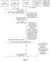
- Step 408 The user equipment A initiates a service acceleration request to the QoS decision network element.
- the service acceleration request includes the user identity of the user equipment A, and the user identity of the user equipment B.
- an acceleration application programming interface Application Programming Interface, API for short
- an acceleration application programming interface Application Programming Interface, API for short
- Step 409 The QoS decision network element sends request signaling to the WebRtc server, and requests to acquire the IP address and the service port number of the user equipment A, and the IP address and the service port number of the user equipment B, where the request signaling includes the user identity of the user equipment A, and the user identity of the user equipment B.
- Step 410 The WebRtc server sends information about an IP and a port number of the user equipment A, and information about the IP address and the service port number of the user equipment B to the QoS decision network element.
- the WebRtc server queries the IP address and the service port number of the user equipment A, and the IP address and the service port number of the user equipment B according to the correspondence, established in step 404 and step 406, between the user identity, and the IP address and the service port number of the user equipment, and sends the IP address and the service port number of the user equipment A, and the IP address and the service port number of the user equipment B to the QoS decision network element.
- Step 411 The QoS decision network element forms a parameter according to the IP address and the service port number of the user equipment A, and the IP address and the service port number of the user equipment B, and sends a QoS improvement request to a PCRF.
- the QoS decision network element may use the IP address and the service port number of the user equipment A as a source address and a source port number, and use the IP address and the service port number of the user equipment B as a destination address and a destination port number, form a parameter and send a request to the PCRF, to perform QoS improvement on the user equipment A.
- the QoS decision network element uses the IP address and the service port number of the user equipment B as a source address and a source port number, uses the IP address and the service port number of the user equipment A as a destination address and a destination port number, forms a parameter and sends a request to the PCRF, to perform QoS improvement on the user equipment B.
- Step 413 The QoS decision network element server returns a QoS improvement result to the user equipment A, to complete QoS improvement.
- a WebRtc server acquires an IP address and a service port number of user equipment A, and an IP address and a service port number of user equipment B, and when receiving request signaling sent by a QoS decision network element to the WebRtc server, sends the IP address and the service port number of the user equipment A, and the IP address and the service port number of the user equipment B to the QoS decision network element, so that a manner in which the user equipment A collects and connects the IP addresses and the service port numbers of the both parties in the prior art is changed, which lightens burden on the user equipment A, reduces difficulty in using the current QoS improvement method by a user, and improves user friendliness.
- FIG. 5 is a schematic flowchart of a QoS improvement method according to Embodiment 4 of the present invention.
- This embodiment is a specific embodiment of Embodiment 1 of the present invention and Embodiment 2 of the present invention.
- a WebRtc server After acquiring an IP address and a service port number of user equipment A, and an IP address and a service port number of user equipment B, a WebRtc server sends the IP address and the service port number of the user equipment A, and the IP address and the service port number of the user equipment B to a QoS decision network element, and the QoS decision network element stores the IP address and the service port number of the user equipment A, and the IP address and the service port number of the user equipment B, so as to perform QoS improvement.
- the QoS improvement method in this embodiment includes the following steps:
- step 404 in Embodiment 3 of the present invention Specifically, reference may be made to step 404 in Embodiment 3 of the present invention.
- Step 505 The WebRtc server sends an IP address and a service port number of the user equipment A that are in the call request signaling to the QoS decision network element.
- the QoS decision network element receives the IP address and the service port number of the user equipment A, and binds the IP address and the service port number of the user equipment A to the user identity of the user equipment A.
- the user identity of the user equipment A is sent by a mobile network to the QoS decision network element when the user equipment A is attached to the mobile network.
- Step 506 The WebRtc server sends the call request signaling of the user equipment A to the user equipment B.
- Step 507 The WebRtc server receives answer signaling sent by the user equipment B.
- step 406 in Embodiment 3 of the present invention Specifically, reference may be made to step 406 in Embodiment 3 of the present invention.
- Step 508 The WebRtc server sends an IP address and a service port number of the user equipment B that are in the answer signaling to the QoS decision network element.
- step 505 and step 508 may be combined and performed, that is, after the WebRtc server acquires the IP address and the service port number of the user equipment A in step 505, the IP address and the service port number of the user equipment A may be buffered to the WebRtc server, and sent to the QoS decision network element together with the IP address and the service port number of the user equipment B that are acquired by the WebRtc server subsequently in step 508, and the IP address and the service port number of the user equipment A and the IP address and the service port number of the user equipment B are bound to a corresponding user identity of the user equipment A, and a corresponding user identity of the user equipment B that are in the QoS decision network element respectively.
- Step 509 The WebRtc server sends the answer signaling of the user equipment B to the user equipment A, to complete establishment of audio and video communication.
- Step 510 The user equipment A initiates a service acceleration request, requests to perform acceleration on a service between the user equipment A and the user equipment B, and invokes an acceleration API of the QoS decision network element.
- the service acceleration request includes the user identity of the user equipment A, and the user identity of the user equipment B.
- Step 511 The QoS decision network element queries the IP address and the service port number of the user equipment A, and the IP address and the service port number of the user equipment B in a local database according to the user identity of the user equipment A, and the user identity of the user equipment B, uses the IP address and the service port number of the user equipment A as a source address and a source port number, uses the IP address and the service port number of the user equipment B as a destination address and a destination port number, forms a parameter and sends a request to a PCRF, to perform QoS improvement on the user equipment A.
- Step 512 The QoS decision network element uses the IP address and the service port number of the user equipment B as a source address and a source port number, uses the IP address and the service port number of the user equipment A as a destination address and a destination port number, forms a parameter and sends a request to the PCRF, to perform QoS improvement on the user equipment B.
- Step 513 The QoS decision network element server returns a QoS improvement result to the user equipment A, to complete QoS improvement.
- a WebRtc server may actively send the IP address and the service port number of the user equipment A, and the IP address and the service port number of the user equipment B to a QoS decision network element, and the QoS decision network element stores the IP address and the service port number of the user equipment A, and the IP address and the service port number of the user equipment B, so as to perform QoS improvement, so that a manner in which the user equipment A collects and connects the IP addresses and the service port numbers of the both parties in the prior art is changed, which lightens burden on the user equipment A, reduces difficulty in using the current QoS improvement method by a user, and improves user friendliness.
- FIG. 6 is a schematic flowchart of a QoS improvement method according to Embodiment 5 of the present invention.
- the method may be performed by any suitable apparatus, for example, a WebRtc server, but the present invention is not limited thereto.
- the QoS improvement method in this embodiment may include the following steps:
- a WebRtc server acquires a service port number of user equipment A, and a service port number of user equipment B, and sends the service port number of the user equipment A, and the service port number of the user equipment B to a QoS decision network element, so as to perform QoS improvement in combination with an IP address of the user equipment A and an IP address of the user equipment B that are in the QoS decision network element, so that a manner in which the user equipment A collects and connects the IP addresses and the service port numbers of the both parties in the prior art is changed, which lightens burden on the user equipment A, and reduces difficulty in using the current QoS improvement method by a user.
- the WebRtc server receives call request signaling sent by the user equipment A to the user equipment B, where the call request signaling includes the IP address and the service port number of the user equipment A, and acquires the IP address and the service port number of the user equipment A from the call request signaling; the WebRtc server sends the call request signaling to the user equipment B; and the WebRtc server receives answer signaling returned by the user equipment B to the user equipment A, where the answer signaling includes the IP address and the service port number of the user equipment B, and acquires the IP address and the service port number of the user equipment B from the answer signaling.
- FIG. 7 is a schematic flowchart of a QoS improvement method according to Embodiment 6 of the present invention.
- the method may be performed by any suitable apparatus, for example, a QoS decision network element, but the present invention is not limited thereto.
- this embodiment may be combined with Embodiment 5 of the present invention.
- the QoS improvement method provided in this embodiment may include the following steps:
- a QoS decision network element receives an IP address of user equipment A, and an IP address of user equipment B that are sent by a mobile network, and receives a service port number of the user equipment A, and a service port number of the user equipment B that are sent by a WebRtc, so as to perform QoS improvement, so that a manner in which the user equipment A collects and connects the IP addresses and the service port numbers of the both parties in the prior art is changed, which lightens burden on the user equipment A, and reduces difficulty in using the current QoS improvement method by a user.
- FIG. 8 is a schematic flowchart of a QoS improvement method according to Embodiment 7 of the present invention.
- This embodiment is a specific embodiment of Embodiment 5 of the present invention and Embodiment 6 of the present invention.
- a WebRtc server acquires a service port number of user equipment A, and a service port number of user equipment B, and sends the service port number of the user equipment A, and the service port number of the user equipment B to a QoS decision network element, so as to perform QoS improvement in combination with an IP address of the user equipment A, and an IP address of the user equipment B that are sent by a mobile network element and received by the QoS decision network element.
- the QoS improvement method in this embodiment includes the following steps:
- the service acceleration request includes the user identity of the user equipment A, and the user identity of the user equipment B.
- the QoS decision network element when the user equipment A and the user equipment B are attached, the QoS decision network element receives the user identity and the IP address of the user equipment A, and the user identity and the IP address of the user equipment B that are from the mobile network; therefore, in this step, after receiving the service acceleration request, the QoS decision network element queries the IP address of the user equipment A, and the IP address of the user equipment B according to the user identity of the user equipment A, and the user identity of the user equipment B that are in the service acceleration request.
- Step 809 The QoS decision network element sends request signaling to the WebRtc server, and requests to acquire the service port number of the user equipment A, and the service port number of the user equipment B, where the request signaling includes the IP address of the user equipment A, and the IP address of the user equipment B.
- Step 810 The WebRtc server sends the service port number of the user equipment A, and the service port number of the user equipment B to the QoS decision network element.
- the WebRtc server queries the service port number of the user equipment A, and the service port number of the user equipment B according to the IP address of the user equipment A, and the IP address of the user equipment B that are sent by the QoS decision network element, and sends the service port number of the user equipment A, and the service port number of the user equipment B to the QoS decision network element.
- step 811 to step 813 reference may be made to step 411 to step 413 in Embodiment 3 of the present invention.
- a WebRtc server acquires a service port number of user equipment A, and a service port number of user equipment B, and sends the service port number of the user equipment A, and the service port number of the user equipment B to a QoS decision network element, so as to perform QoS improvement in combination with an IP address of the user equipment A and an IP address of the user equipment B that are sent by a mobile network element and received by the QoS decision network element, so that a manner in which the user equipment A collects and connects the IP addresses and the service port numbers of the both parties in the prior art is changed, which lightens burden on the user equipment A, reduces difficulty in using the current QoS improvement method by a user, and improves user friendliness.
- FIG. 9 is a schematic block diagram of a QoS improvement apparatus 900 according to Embodiment 8 of the present invention.
- the QoS improvement apparatus may be a WebRtc server, but this embodiment of the present invention is not limited thereto.
- the QoS improvement apparatus provided in this embodiment of the present invention includes:
- the QoS improvement apparatus in this embodiment of the present invention receives an IP address and a service port number of user equipment A, and an IP address and a service port number of user equipment B, and sends the IP address and the service port number of the user equipment A, and the IP address and the service port number of the user equipment B to a QoS decision network element, so that a manner in which the user equipment A collects and connects the IP addresses and the service port numbers of the both parties in the prior art is changed, which lightens burden on the user equipment A, and reduces difficulty in using the current QoS improvement method by a user.
- the receiving module 901 is specifically configured to receive call request signaling sent by the user equipment A to the user equipment B, where the call request signaling includes the IP address and the service port number of the user equipment A, and acquire the IP address and the service port number of the user equipment A from the call request signaling; the sending module 902 is further configured to send the call request signaling to the user equipment B; and the receiving module 901 is specifically configured to receive answer signaling returned by the user equipment B to the user equipment A, where the answer signaling includes the IP address and the service port number of the user equipment B, and acquire the IP address and the service port number of the user equipment B from the answer signaling.
- the apparatus includes a processing module 903, where the processing module is configured to: after the receiving module receives the IP address and the service port number of the user equipment A, and the IP address and the service port number of the user equipment B, bind the received IP address and service port number of the user equipment A, and the received IP address and service port number of the user equipment B to a user identity of the user equipment A corresponding to the received IP address and service port number of the user equipment A, and a user identity of the user equipment B corresponding to the received IP address and service port number of the user equipment B respectively; the receiving module 901 is further configured to receive request signaling sent by the QoS decision network element, and request to acquire the IP addresses and the service port numbers of the both parties of the user equipments, where the request signaling includes the user identities of the both parties of the user equipments; and the sending module 902 being configured to send the IP address and the service port number of the user equipment A, and the IP address and the service port number of the user equipment B to a QoS decision network element is specifically: sending
- the sending module 902 is specifically configured to: after the receiving module 901 receives the call request signaling sent by the user equipment A to the user equipment B, send the IP address and the service port number of the user equipment A to the QoS decision network element; and after the receiving module 901 receives the answer signaling returned by the user equipment B to the user equipment A, send the IP address and the service port number of the user equipment B to the QoS decision network element.
- the sending module 902 is specifically configured to: after the receiving module 901 receives the answer signaling returned by the user equipment B to the user equipment A, send the IP address and the service port number of the user equipment A, and the IP address and the service port number of the user equipment B to the QoS decision network element.
- FIG. 10 is a schematic block diagram of another QoS improvement apparatus 1000 according to Embodiment 9 of the present invention.
- the QoS improvement apparatus may be a QoS decision network element, but this embodiment of the present invention is not limited thereto.
- the QoS improvement apparatus provided in this embodiment may be combined with the QoS improvement apparatus provided in Embodiment 8 of the present invention.
- the QoS improvement apparatus may include:
- the QoS improvement apparatus in this embodiment of the present invention receives an IP address and a service port number of user equipment A, and an IP address and a service port number of user equipment B that are sent by a WebRtc server, so that a manner in which the user equipment A collects and connects the IP addresses and the service port numbers of the both parties in the prior art is changed, which lightens burden on the user equipment A, and reduces difficulty in using the current QoS improvement method by a user.
- the service acceleration request includes a user identity of the user equipment A, and a user identity of the user equipment B
- the sending apparatus 1002 is further configured to send request signaling to the WebRtc server, and request to acquire the IP address and the service port number of the user equipment A, and the IP address and the service port number of the user equipment B, where the request signaling includes the user identity of the user equipment A, and the user identity of the user equipment B
- the receiving module 1001 being configured to receive an IP address and a service port number of user equipment A, and an IP address and a service port number of user equipment B that are sent by a WebRtc server specifically includes: the receiving module 1001 being configured to receive the IP address and the service port number of the user equipment A, and the IP address and the service port number of the user equipment B that are returned by the WebRtc server according to the user identity of the user equipment A, and the user identity of the user equipment B.
- FIG. 11 is a schematic block diagram of another QoS improvement apparatus according to Embodiment 10 of the present invention.
- the QoS improvement apparatus may be a WebRtc server, but this embodiment of the present invention is not limited thereto.
- the QoS improvement apparatus provided in this embodiment of the present invention includes:
- the receiving module 1101 is specifically configured to receive call request signaling sent by the user equipment A to the user equipment B, where the call request signaling includes the IP address and the service port number of the user equipment A, and acquire the IP address and the service port number of the user equipment A from the call request signaling; and receive answer signaling returned by the user equipment B to the user equipment A, where the answer signaling includes the IP address and the service port number of the user equipment B, and acquire the IP address and the service port number of the user equipment B from the answer signaling; and the sending module 1102 is further configured to: after the receiving module 1101 receives the call request signaling sent by the user equipment A to the user equipment B, send the call request signaling to the user equipment B.
- the QoS improvement apparatus in this embodiment of the present invention receives a service port number of user equipment A, and a service port number of user equipment B, and sends the service port number of the user equipment A, and the service port number of the user equipment B to a QoS decision network element, so as to perform QoS improvement in combination with an IP address of the user equipment A and an IP address of the user equipment B that are in the QoS decision network element, so that a manner in which the user equipment A collects and connects the IP addresses and the service port numbers of the both parties in the prior art is changed, which lightens burden on the user equipment A, reduces difficulty in using the current QoS improvement method by a user, and improves user friendliness.
- FIG. 12 is a schematic block diagram of a QoS improvement apparatus according to Embodiment 11 of the present invention.
- the QoS improvement apparatus may be a QoS decision network element, but this embodiment of the present invention is not limited thereto.
- this embodiment of the present invention is not limited thereto.
- the QoS improvement apparatus includes:
- a query module 1203 configured to obtain the IP address of the user equipment A, and the IP address of the user
- the QoS improvement apparatus in this embodiment of the present invention receives an IP address of user equipment A, and an IP address of user equipment B that are sent by a mobile network, so as to perform QoS improvement in combination with a service port number of the user equipment A, and a service port number of the user equipment B that are sent by a WebRtc server, so that a manner in which the user equipment A collects and connects the IP addresses and the service port numbers of the both parties in the prior art is changed, which lightens burden on the user equipment A, reduces difficulty in using the current QoS improvement method by a user, and improves user friendliness.
- FIG. 13 is a schematic block diagram of a QoS improvement apparatus according to Embodiment 12 of the present invention.
- the QoS improvement apparatus may be a WebRtc server, but this embodiment of the present invention is not limited thereto.
- the QoS improvement apparatus provided in this embodiment includes:
- the QoS improvement apparatus in this embodiment of the present invention receives an IP address and a service port number of user equipment A, and an IP address and a service port number of user equipment B, and sends the IP address and the service port number of the user equipment A, and the IP address and the service port number of the user equipment B to a QoS decision network element, so that a manner in which the user equipment A collects and connects the IP addresses and the service port numbers of the both parties in the prior art is changed, which lightens burden on the user equipment A, reduces difficulty in using the current QoS improvement method by a user, and improves user friendliness.
- the receiver 1301 is specifically configured to receive call request signaling sent by the user equipment A to the user equipment B, where the call request signaling includes the IP address and the service port number of the user equipment A, and acquire the IP address and the service port number of the user equipment A from the call request signaling; the transmitter 1302 is further configured to send the call request signaling to the user equipment B; and the receiver 1301 is specifically configured to receive answer signaling returned by the user equipment B to the user equipment A, where the answer signaling includes the IP address and the service port number of the user equipment B, and acquire the IP address and the service port number of the user equipment B from the answer signaling.
- the apparatus includes a processor 1303, where the processor 1303 is configured to: after the receiving module receives the IP address and the service port number of the user equipment A, and the IP address and the service port number of the user equipment B, bind the received IP address and service port number of the user equipment A, and the received IP address and service port number of the user equipment B to a user identity of the user equipment A corresponding to the received IP address and service port number of the user equipment A, and a user identity of the user equipment B corresponding to the received IP address and service port number of the user equipment B respectively; the receiver 1301 is further configured to receive request signaling sent by the QoS decision network element, and request to acquire the IP addresses and the service port numbers of the both parties of the user equipments, where the request signaling includes the user identities of the both parties of the user equipments; and the transmitter 1302 being configured to send the IP address and the service port number of the user equipment A, and the IP address and the service port number of the user equipment B to a QoS decision network element is specifically: sending, according to the
- the transmitter 1302 is specifically configured to: after the receiver 1301 receives the call request signaling sent by the user equipment A to the user equipment B, send the IP address and the service port number of the user equipment A to the QoS decision network element; and after the receiver 1301 receives the answer signaling returned by the user equipment B to the user equipment A, send the IP address and the service port number of the user equipment B to the QoS decision network element.
- the transmitter 1302 is specifically configured to: after the receiver 1301 receives the answer signaling returned by the user equipment B to the user equipment A, send the IP address and the service port number of the user equipment A, and the IP address and the service port number of the user equipment B to the QoS decision network element.
- the apparatus provided in Embodiment 12 of the present invention may be a central processing unit (Central Processing Unit, "CPU” for short), and may also be another general purpose processor, a digital signal processor (DSP), an application specific integrated circuit (ASIC), a field programmable gate array (FPGA) or another programmable logic device, a discrete gate or a transistor logic device, a discrete hardware component, or the like.
- the general purpose processor may be a microprocessor or the processor may also be any conventional processor.
- the foregoing steps may be completed by using an integrated logic circuit of hardware or an instruction in a software form in the apparatus provided in Embodiment 12 of the present invention, and in combination with the steps of the methods disclosed in the embodiments of the present invention, may be directly embodied as being performed and completed by a hardware processor, or performed and completed by using a combination of hardware and software modules in a processor.
- the software module may be located in a storage medium that is mature in the art, such as a random access memory, a flash memory, a read-only memory, a programmable read-only memory or an electrically erasable programmable memory, or a register.
- the storage medium is located in a memory.
- the apparatus provided in Embodiment 12 of the present invention reads information in a memory, and completes the steps of the foregoing methods in combination with hardware of the apparatus. Details are not described herein again to avoid repetition.
- FIG. 14 is a schematic block diagram of another QoS improvement apparatus according to Embodiment 13 of the present invention.
- the QoS improvement apparatus may be a QoS decision network element, but this embodiment of the present invention is not limited thereto.
- the QoS improvement apparatus provided in this embodiment and the QoS improvement apparatus provided in Embodiment 12 of the present invention reference may be made to each other.
- the QoS improvement apparatus may include:
- the QoS improvement apparatus receives an IP address and a service port number of user equipment A, and an IP address and a service port number of user equipment B that are sent by a WebRtc server, so that a manner in which the user equipment A collects and connects the IP addresses and the service port numbers of the both parties in the prior art is changed, which lightens burden on the user equipment A, reduces difficulty in using the current QoS improvement method by a user, and improves user friendliness.
- the service acceleration request includes a user identity of the user equipment A, and a user identity of the user equipment B
- the transmitter 1402 is further configured to send request signaling to the WebRtc server, and request to acquire the IP address and the service port number of the user equipment A, and the IP address and the service port number of the user equipment B, where the request signaling includes the user identity of the user equipment A, and the user identity of the user equipment B
- the receiver 1401 being configured to receive an IP address and a service port number of user equipment A, and an IP address and a service port number of user equipment B that are sent by a WebRtc server specifically includes: the receiver 1401 being configured to receive the IP address and the service port number of the user equipment A, and the IP address and the service port number of the user equipment B that are returned by the WebRtc server according to the user identity of the user equipment A, and the user identity of the user equipment B.
- the apparatus provided in Embodiment 13 of the present invention may be a central processing unit (Central Processing Unit, "CPU” for short), and may also be another general purpose processor, a digital signal processor (DSP), an application specific integrated circuit (ASIC), a field programmable gate array (FPGA) or another programmable logic device, a discrete gate or a transistor logic device, a discrete hardware component, or the like.
- the general purpose processor may be a microprocessor or the processor may also be any conventional processor.
- the foregoing steps may be completed by using an integrated logic circuit of hardware or an instruction in a software form in the apparatus provided in Embodiment 13 of the present invention, and in combination with the steps of the methods disclosed in the embodiments of the present invention, may be directly embodied as being performed and completed by a hardware processor, or performed and completed by using a combination of hardware and software modules in a processor.
- the software module may be located in a storage medium that is mature in the art, such as a random access memory, a flash memory, a read-only memory, a programmable read-only memory or an electrically erasable programmable memory, or a register.
- the storage medium is located in a memory.
- the apparatus provided in Embodiment 13 of the present invention reads information in a memory, and completes the steps of the foregoing methods in combination with hardware of the apparatus. Details are not described herein again to avoid repetition.
- FIG. 15 is a schematic block diagram of another QoS improvement apparatus according to Embodiment 14 of the present invention.
- the QoS improvement apparatus may be a WebRtc server, but this embodiment of the present invention is not limited thereto.
- the QoS improvement apparatus provided in this embodiment of the present invention includes:
- the receiver 1501 is specifically configured to receive call request signaling sent by the user equipment A to the user equipment B, where the call request signaling includes the IP address and the service port number of the user equipment A, and acquire the IP address and the service port number of the user equipment A from the call request signaling; and receive answer signaling returned by the user equipment B to the user equipment A, where the answer signaling includes the IP address and the service port number of the user equipment B, and acquire the IP address and the service port number of the user equipment B from the answer signaling; and the transmitter 1502 is further configured to: after the receiving module 1101 receives the call request signaling sent by the user equipment A to the user equipment B, send the call request signaling to the user equipment B.
- the QoS improvement apparatus in this embodiment of the present invention acquires a service port number of user equipment A, and a service port number of user equipment B, and sends the service port number of the user equipment A, and the service port number of the user equipment B to a QoS decision network element, so as to perform QoS improvement in combination with an IP address of the user equipment A and an IP address of the user equipment B that are in the QoS decision network element, so that a manner in which the user equipment A collects and connects the IP addresses and the service port numbers of the both parties in the prior art is changed, which lightens burden on the user equipment A, and reduces difficulty in using the current QoS improvement method by a user.
- the apparatus provided in Embodiment 14 of the present invention may be a central processing unit (Central Processing Unit, "CPU” for short), and may also be another general purpose processor, a digital signal processor (DSP), an application specific integrated circuit (ASIC), a field programmable gate array (FPGA) or another programmable logic device, a discrete gate or a transistor logic device, a discrete hardware component, or the like.
- the general purpose processor may be a microprocessor or the processor may also be any conventional processor.
- the foregoing steps may be completed by using an integrated logic circuit of hardware or an instruction in a software form in the apparatus provided in Embodiment 14 of the present invention, and in combination with the steps of the methods disclosed in the embodiments of the present invention, may be directly embodied as being performed and completed by a hardware processor, or performed and completed by using a combination of hardware and software modules in a processor.
- the software module may be located in a storage medium that is mature in the art, such as a random access memory, a flash memory, a read-only memory, a programmable read-only memory or an electrically erasable programmable memory, or a register.
- the storage medium is located in a memory.
- the apparatus provided in Embodiment 14 of the present invention reads information in a memory, and completes the steps of the foregoing methods in combination with hardware of the apparatus. Details are not described herein again to avoid repetition.
- FIG. 16 is a schematic block diagram of a QoS improvement apparatus according to Embodiment 15 of the present invention.
- the QoS improvement apparatus may be a QoS decision network element, but this embodiment of the present invention is not limited thereto.
- this embodiment of the present invention is not limited thereto.
- the QoS improvement apparatus includes:
- the QoS improvement apparatus in this embodiment of the present invention receives an IP address of user equipment A, and an IP address of user equipment B that are sent by a mobile network, so as to perform QoS improvement in combination with a service port number of the user equipment A, and a service port number of the user equipment B that are sent by a WebRtc server, so that a manner in which the user equipment A collects and connects the IP addresses and the service port numbers of the both parties in the prior art is changed, which lightens burden on the user equipment A, and reduces difficulty in using the current QoS improvement method by a user.
- the apparatus provided in Embodiment 15 of the present invention may be a central processing unit (Central Processing Unit, "CPU” for short), and may also be another general purpose processor, a digital signal processor (DSP), an application specific integrated circuit (ASIC), a field programmable gate array (FPGA) or another programmable logic device, a discrete gate or a transistor logic device, a discrete hardware component, or the like.
- the general purpose processor may be a microprocessor or the processor may also be any conventional processor.
- the foregoing steps may be completed by using an integrated logic circuit of hardware or an instruction in a software form in the apparatus provided in Embodiment 15 of the present invention, and in combination with the steps of the methods disclosed in the embodiments of the present invention, may be directly embodied as being performed and completed by a hardware processor, or performed and completed by using a combination of hardware and software modules in a processor.
- the software module may be located in a storage medium that is mature in the art, such as a random access memory, a flash memory, a read-only memory, a programmable read-only memory or an electrically erasable programmable memory, or a register.
- the storage medium is located in a memory.
- the apparatus provided in Embodiment 15 of the present invention reads information in a memory, and completes the steps of the foregoing methods in combination with hardware of the apparatus. Details are not described herein again to avoid repetition.
- FIG. 17 is a schematic structural diagram of a QoS improvement system according to Embodiment 16 of the present invention.
- the QoS improvement system may include a WebRtc server and a QoS decision network element, but this embodiment of the present invention is not limited thereto.
- the QoS improvement system provided in this embodiment of the present invention includes:
- the functions of the WebRtc servers in Embodiments 1, 3 and 4 of the present invention may be implemented by the WebRtc server 1701 in the QoS improvement system provided in this embodiment; and the functions of the QoS decision network elements in Embodiments 2, 3 and 4 of the present invention may be implemented by the QoS decision network element 1702 in the QoS improvement system provided in this embodiment.
- the WebRtc server 1701 is specifically configured to receive call request signaling sent by the user equipment A to the user equipment B, where the call request signaling includes the IP address and the service port number of the user equipment A, and acquire the IP address and the service port number of the user equipment A from the call request signaling; the WebRtc server 1701 is further configured to: after receiving the call request signaling sent by the user equipment A to the user equipment B, send the call request signaling to the user equipment B; and the WebRtc server 1701 is specifically configured to receive answer signaling returned by the user equipment B to the user equipment A, where the answer signaling includes the IP address and the service port number of the user equipment B, and acquire the IP address and the service port number of the user equipment B from the answer signaling.
- the WebRtc server 1701 is further configured to: after receiving the IP address and the service port number of the user equipment A, and the IP address and the service port number of the user equipment B, bind the received IP address and service port number of the user equipment A, and the received IP address and service port number of the user equipment B to a user identity of the user equipment A corresponding to the received IP address and service port number of the user equipment A, and a user identity of the user equipment B corresponding to the received IP address and service port number of the user equipment B respectively; the QoS decision network element 1702 is specifically configured to receive a service acceleration request sent by the user equipment A, where the service acceleration request includes the user identity of the user equipment A, and the user identity of the user equipment B; and send request signaling to the WebRtc server 1701, and request to acquire the IP address and the service port number of the user equipment A, and the IP address and the service port number of the user equipment B, where the request signaling includes the user identity of the user equipment A, and the user identity of the user equipment B
- the WebRtc server 1701 being configured to send the IP address and the service port number of the user equipment A, and the IP address and the service port number of the user equipment B to the QoS decision network element specifically includes: the WebRtc server 1701 being configured to: after receiving the call request signaling sent by the user equipment A to the user equipment B, send the IP address and the service port number of the user equipment A to the QoS decision network element 1702; and after receiving the answer signaling returned by the user equipment B to the user equipment A, send the IP address and the service port number of the user equipment B to the QoS decision network element.
- the WebRtc server 1701 being configured to send the IP address and the service port number of the user equipment A, and the IP address and the service port number of the user equipment B to the QoS decision network element 1702 specifically includes: the WebRtc server 1701 being configured to: after receiving the answer signaling returned by the user equipment B to the user equipment A, send the IP address and the service port number of the user equipment A, and the IP address and the service port number of the user equipment B to the QoS decision network element 1702.
- a WebRtc server acquires an IP address and a service port number of user equipment A, and an IP address and a service port number of user equipment B, and sends the IP address and the service port number of the user equipment A, and the IP address and the service port number of the user equipment B to a QoS decision network element, so that a manner in which the user equipment A collects and connects the IP addresses and the service port numbers of the both parties in the prior art is changed, which lightens burden on the user equipment A, and reduces difficulty in using the current QoS improvement method by a user.
- FIG. 18 is a schematic structural diagram of a QoS improvement system according to Embodiment 17 of the present invention.
- the QoS improvement system may include a WebRtc server and a QoS decision network element, but this embodiment of the present invention is not limited thereto.
- the QoS improvement system provided in this embodiment of the present invention includes:
- the WebRtc server 1801 is specifically configured to receive call request signaling sent by the user equipment A to the user equipment B, where the call request signaling includes the IP address and the service port number of the user equipment A, and acquire the IP address and the service port number of the user equipment A from the call request signaling; the WebRtc server 1801 is further configured to: after the receiving module receives the call request signaling sent by the user equipment A to the user equipment B, send the call request signaling to the user equipment B; and the WebRtc server 1801 is specifically configured to receive answer signaling returned by the user equipment B to the user equipment A, where the answer signaling includes the IP address and the service port number of the user equipment B, and acquire the IP address and the service port number of the user equipment B from the answer signaling.
- the QoS decision network element 1802 being configured to receive the IP address of the user equipment A, and the IP address of the user equipment B that are sent by a mobile network includes: the QoS decision network element 1802 being configured to: when the user equipment A is attached, receive the IP address and a user identity of the user equipment A that are sent by the mobile network; and when the user equipment B is attached, receive the IP address and a user identity of the user equipment B that are sent by the mobile network; and when the service acceleration request sent by the user equipment A that the QoS decision network element 1802 is configured to receive includes the user identity of the user equipment A, and the user identity of the user equipment B, before the QoS decision network element 1802 is configured to send the request signaling to the WebRtc server, the QoS decision network element 1802 being configured to receive the IP address of the user equipment A, and the IP address of the user equipment B that are sent by a mobile network further includes: the QoS decision network element 1802 being configured to obtain the IP address of the user equipment A, and
- the functions of the WebRtc servers in Embodiments 5 and 7 of the present invention may be implemented by the WebRtc server 1801 in the QoS improvement system provided in this embodiment; and the functions of the QoS decision network elements in Embodiments 6 and 7 of the present invention may be implemented by the QoS decision network element 1802 in the QoS improvement system provided in this embodiment.
- a WebRtc server acquires a service port number of user equipment A, and a service port number of user equipment B, and sends the service port number of the user equipment A, and the service port number of the user equipment B to a QoS decision network element, so as to perform QoS improvement in combination with an IP address of the user equipment A and an IP address of the user equipment B that are in the QoS decision network element, so that a manner in which the user equipment A collects and connects the IP addresses and the service port numbers of the both parties in the prior art is changed, which lightens burden on the user equipment A.
- the disclosed system, apparatus, and method may be implemented in other manners.
- the described apparatus embodiment is merely exemplary.
- the unit division is merely logical function division and may be other division in actual implementation.
- a plurality of units or components may be combined or integrated into another system, or some features may be ignored or not performed.
- the displayed or discussed mutual couplings or direct couplings or communication connections may be implemented through some interfaces.
- the indirect couplings or communication connections between the apparatuses or units may be implemented in electronic, mechanical, or other forms.
- the units described as separate parts may or may not be physically separate, and parts displayed as units may or may not be physical units, may be located in one position, or may be distributed on a plurality of network units. A part or all of the units may be selected according to actual needs to achieve the objectives of the solutions of the embodiments of the present invention.
- functional units in the embodiments of the present invention may be integrated into one processing unit, or each of the units may exist alone physically, or two or more units are integrated into one unit.
- the integrated unit may be implemented in a form of hardware, or may be implemented in a form of a software functional unit.
- the integrated unit When the integrated unit is implemented in the form of a software functional unit and sold or used as an independent product, the integrated unit may be stored in a computer-readable storage medium. Based on such an understanding, the technical solutions of the present invention essentially, or the part contributing to the prior art, or all or a part of the technical solutions may be implemented in the form of a software product.
- the software product is stored in a storage medium and includes several instructions for instructing a computer device (which may be a personal computer, a server, or a network device) to perform all or a part of the steps of the methods described in the embodiments of the present invention.
- the foregoing storage medium includes: any medium that can store program code, such as a USB flash drive, a removable hard disk, a read-only memory (Read-Only Memory, ROM for short), a random access memory (Random Access Memory, RAM for short), a magnetic disk, or an optical disc.
- program code such as a USB flash drive, a removable hard disk, a read-only memory (Read-Only Memory, ROM for short), a random access memory (Random Access Memory, RAM for short), a magnetic disk, or an optical disc.
Landscapes
- Engineering & Computer Science (AREA)
- Computer Networks & Wireless Communication (AREA)
- Signal Processing (AREA)
- Multimedia (AREA)
- Business, Economics & Management (AREA)
- General Business, Economics & Management (AREA)
- Computer Security & Cryptography (AREA)
- Telephonic Communication Services (AREA)
- Data Exchanges In Wide-Area Networks (AREA)
Applications Claiming Priority (1)
| Application Number | Priority Date | Filing Date | Title |
|---|---|---|---|
| PCT/CN2013/089179 WO2015085531A1 (fr) | 2013-12-12 | 2013-12-12 | Procédé, dispositif et système pour améliorer la qos |
Publications (3)
| Publication Number | Publication Date |
|---|---|
| EP3073691A1 true EP3073691A1 (fr) | 2016-09-28 |
| EP3073691A4 EP3073691A4 (fr) | 2016-11-30 |
| EP3073691B1 EP3073691B1 (fr) | 2020-09-16 |
Family
ID=53370490
Family Applications (1)
| Application Number | Title | Priority Date | Filing Date |
|---|---|---|---|
| EP13899184.9A Active EP3073691B1 (fr) | 2013-12-12 | 2013-12-12 | Procédé et dispositif pour améliorer la qos |
Country Status (4)
| Country | Link |
|---|---|
| US (1) | US10129320B2 (fr) |
| EP (1) | EP3073691B1 (fr) |
| CN (1) | CN105814853B (fr) |
| WO (1) | WO2015085531A1 (fr) |
Families Citing this family (3)
| Publication number | Priority date | Publication date | Assignee | Title |
|---|---|---|---|---|
| FR3022093A1 (fr) | 2014-06-10 | 2015-12-11 | Orange | Procede d'etablissement d'une session webrtc |
| CN108418789B (zh) * | 2018-01-22 | 2021-09-17 | 网宿科技股份有限公司 | 一种基于WebRTC的通信系统及其通信方法、信令服务器 |
| EP3766277B1 (fr) * | 2018-03-12 | 2024-06-26 | Privilege Wireless Llc | Procédé de mesure de la qualité de service dans un réseau de communication sans fil |
Family Cites Families (13)
| Publication number | Priority date | Publication date | Assignee | Title |
|---|---|---|---|---|
| JP4449901B2 (ja) * | 2003-04-09 | 2010-04-14 | 日本電気株式会社 | 無線ネットワーク制御装置及びそれに用いるQoS制御方法 |
| CN101009631A (zh) * | 2006-01-24 | 2007-08-01 | 华为技术有限公司 | 一种QoS控制方法和系统 |
| KR101685471B1 (ko) * | 2011-04-18 | 2016-12-20 | 닛본 덴끼 가부시끼가이샤 | 단말, 제어 디바이스, 통신 방법, 통신 시스템, 통신 모듈, 프로그램을 기록한 컴퓨터 판독 가능한 기록 매체, 및 정보 처리 디바이스 |
| CN102905390B (zh) * | 2011-07-26 | 2017-12-01 | 中兴通讯股份有限公司 | 会话关联方法、装置和系统 |
| CN103037449B (zh) * | 2011-10-10 | 2018-01-19 | 中兴通讯股份有限公司 | 一种更新服务质量的方法及系统 |
| CN102904930B (zh) * | 2012-09-17 | 2016-01-20 | 中兴通讯股份有限公司 | 内容和网络联动的双重加速方法及系统 |
| US9282046B1 (en) * | 2012-11-15 | 2016-03-08 | Qlogic, Corporation | Smoothing FIFO and methods thereof |
| US9668166B2 (en) * | 2013-02-05 | 2017-05-30 | Qualcomm Incorporated | Quality of service for web client based sessions |
| EP2947825A4 (fr) * | 2013-03-08 | 2016-02-17 | Huawei Device Co Ltd | Procédé de communication vidéo, terminal domestique et serveur domestique |
| US9917849B2 (en) * | 2013-05-01 | 2018-03-13 | Fortinet, Inc. | Security system for physical or virtual environments |
| US9288686B2 (en) * | 2013-10-17 | 2016-03-15 | Telefonaktiebolaget L M Ericsson (Publ) | Topology discovery based on SCTP/X2 snooping |
| US10320676B2 (en) * | 2014-02-28 | 2019-06-11 | Cisco Technology, Inc. | Smarter policy decisions based on metadata in data flows |
| WO2015199462A1 (fr) * | 2014-06-27 | 2015-12-30 | Samsung Electronics Co., Ltd. | Procédé et appareil pour fournir une qualité de service pour une communication en temps réel reposant sur le web |
-
2013
- 2013-12-12 EP EP13899184.9A patent/EP3073691B1/fr active Active
- 2013-12-12 CN CN201380081517.1A patent/CN105814853B/zh active Active
- 2013-12-12 WO PCT/CN2013/089179 patent/WO2015085531A1/fr not_active Ceased
-
2016
- 2016-06-08 US US15/176,844 patent/US10129320B2/en active Active
Also Published As
| Publication number | Publication date |
|---|---|
| US10129320B2 (en) | 2018-11-13 |
| EP3073691B1 (fr) | 2020-09-16 |
| CN105814853A (zh) | 2016-07-27 |
| CN105814853B (zh) | 2019-10-25 |
| US20160285946A1 (en) | 2016-09-29 |
| WO2015085531A1 (fr) | 2015-06-18 |
| EP3073691A4 (fr) | 2016-11-30 |
Similar Documents
| Publication | Publication Date | Title |
|---|---|---|
| US10250646B2 (en) | Method and device for establishing channel | |
| WO2020103523A1 (fr) | Procédé de sélection de tranche de réseau, dispositif de réseau et terminal | |
| CN103888539B (zh) | P2p缓存的引导方法、装置及p2p缓存系统 | |
| US20150085865A1 (en) | Method and system for dynamically allocating services for subscribers data traffic | |
| EP3089422A1 (fr) | Procédé, appareil, et système de distribution de contenu | |
| CN111092842B (zh) | 一种信息处理方法、服务器、网元及存储介质 | |
| CN114080056A (zh) | 一种会话更新方法、终端和网络侧设备 | |
| CN110392069B (zh) | Cdn业务调度处理方法及cdn服务器 | |
| CN104854841A (zh) | 应用服务器、终端设备、网络能力调用系统及方法 | |
| US10129320B2 (en) | QoS improvement method, apparatus, and system | |
| US10631145B1 (en) | Dynamic provision of application related sponsored data connectivity | |
| US10700879B2 (en) | Charging method and device, access device, service quality control method and device | |
| US10581979B2 (en) | Information transmission method and apparatus | |
| CN111050355A (zh) | 动态调整移动终端Qos的方法、装置及系统 | |
| CN109309907B (zh) | 用于流量计费的方法、装置及其相关设备 | |
| US10205659B2 (en) | Information transmission using direct HPCRF communications | |
| CN104917742B (zh) | 一种信息传送方法及装置 | |
| CN113423078B (zh) | 应用程序网络分片选择方法、应用服务器及pcf | |
| CN106878352A (zh) | 一种实现远程访问的方法、AllJoyn网关代理、云服务器及移动设备 | |
| CN103188167A (zh) | 业务质量保障方法、装置和系统 | |
| CN121842767A (zh) | 多模态业务协同通信方法、装置、电子设备及存储介质 | |
| KR20240045981A (ko) | 무선 통신 시스템에서 sfc 서비스 익스포저 기능을 제공하기 위한 장치 및 방법 | |
| KR20070028461A (ko) | 통신 네트워크에서 서비스 품질 관리를 위한 메커니즘 | |
| CN104995893A (zh) | 一种数据处理方法、设备和系统 | |
| CN108667879A (zh) | 数据业务会话绑定方法和路由设备及系统 |
Legal Events
| Date | Code | Title | Description |
|---|---|---|---|
| PUAI | Public reference made under article 153(3) epc to a published international application that has entered the european phase |
Free format text: ORIGINAL CODE: 0009012 |
|
| 17P | Request for examination filed |
Effective date: 20160620 |
|
| AK | Designated contracting states |
Kind code of ref document: A1 Designated state(s): AL AT BE BG CH CY CZ DE DK EE ES FI FR GB GR HR HU IE IS IT LI LT LU LV MC MK MT NL NO PL PT RO RS SE SI SK SM TR |
|
| AX | Request for extension of the european patent |
Extension state: BA ME |
|
| A4 | Supplementary search report drawn up and despatched |
Effective date: 20161031 |
|
| RIC1 | Information provided on ipc code assigned before grant |
Ipc: H04L 12/917 20130101AFI20161025BHEP Ipc: H04L 29/06 20060101ALI20161025BHEP |
|
| DAX | Request for extension of the european patent (deleted) | ||
| STAA | Information on the status of an ep patent application or granted ep patent |
Free format text: STATUS: EXAMINATION IS IN PROGRESS |
|
| 17Q | First examination report despatched |
Effective date: 20180117 |
|
| GRAP | Despatch of communication of intention to grant a patent |
Free format text: ORIGINAL CODE: EPIDOSNIGR1 |
|
| STAA | Information on the status of an ep patent application or granted ep patent |
Free format text: STATUS: GRANT OF PATENT IS INTENDED |
|
| INTG | Intention to grant announced |
Effective date: 20200528 |
|
| GRAS | Grant fee paid |
Free format text: ORIGINAL CODE: EPIDOSNIGR3 |
|
| GRAA | (expected) grant |
Free format text: ORIGINAL CODE: 0009210 |
|
| STAA | Information on the status of an ep patent application or granted ep patent |
Free format text: STATUS: THE PATENT HAS BEEN GRANTED |
|
| AK | Designated contracting states |
Kind code of ref document: B1 Designated state(s): AL AT BE BG CH CY CZ DE DK EE ES FI FR GB GR HR HU IE IS IT LI LT LU LV MC MK MT NL NO PL PT RO RS SE SI SK SM TR |
|
| REG | Reference to a national code |
Ref country code: GB Ref legal event code: FG4D |
|
| REG | Reference to a national code |
Ref country code: CH Ref legal event code: EP |
|
| REG | Reference to a national code |
Ref country code: DE Ref legal event code: R096 Ref document number: 602013072673 Country of ref document: DE |
|
| REG | Reference to a national code |
Ref country code: IE Ref legal event code: FG4D |
|
| REG | Reference to a national code |
Ref country code: AT Ref legal event code: REF Ref document number: 1315162 Country of ref document: AT Kind code of ref document: T Effective date: 20201015 |
|
| PG25 | Lapsed in a contracting state [announced via postgrant information from national office to epo] |
Ref country code: BG Free format text: LAPSE BECAUSE OF FAILURE TO SUBMIT A TRANSLATION OF THE DESCRIPTION OR TO PAY THE FEE WITHIN THE PRESCRIBED TIME-LIMIT Effective date: 20201216 Ref country code: NO Free format text: LAPSE BECAUSE OF FAILURE TO SUBMIT A TRANSLATION OF THE DESCRIPTION OR TO PAY THE FEE WITHIN THE PRESCRIBED TIME-LIMIT Effective date: 20201216 Ref country code: GR Free format text: LAPSE BECAUSE OF FAILURE TO SUBMIT A TRANSLATION OF THE DESCRIPTION OR TO PAY THE FEE WITHIN THE PRESCRIBED TIME-LIMIT Effective date: 20201217 Ref country code: HR Free format text: LAPSE BECAUSE OF FAILURE TO SUBMIT A TRANSLATION OF THE DESCRIPTION OR TO PAY THE FEE WITHIN THE PRESCRIBED TIME-LIMIT Effective date: 20200916 Ref country code: SE Free format text: LAPSE BECAUSE OF FAILURE TO SUBMIT A TRANSLATION OF THE DESCRIPTION OR TO PAY THE FEE WITHIN THE PRESCRIBED TIME-LIMIT Effective date: 20200916 Ref country code: FI Free format text: LAPSE BECAUSE OF FAILURE TO SUBMIT A TRANSLATION OF THE DESCRIPTION OR TO PAY THE FEE WITHIN THE PRESCRIBED TIME-LIMIT Effective date: 20200916 |
|
| REG | Reference to a national code |
Ref country code: AT Ref legal event code: MK05 Ref document number: 1315162 Country of ref document: AT Kind code of ref document: T Effective date: 20200916 |
|
| REG | Reference to a national code |
Ref country code: NL Ref legal event code: MP Effective date: 20200916 |
|
| PG25 | Lapsed in a contracting state [announced via postgrant information from national office to epo] |
Ref country code: LV Free format text: LAPSE BECAUSE OF FAILURE TO SUBMIT A TRANSLATION OF THE DESCRIPTION OR TO PAY THE FEE WITHIN THE PRESCRIBED TIME-LIMIT Effective date: 20200916 Ref country code: RS Free format text: LAPSE BECAUSE OF FAILURE TO SUBMIT A TRANSLATION OF THE DESCRIPTION OR TO PAY THE FEE WITHIN THE PRESCRIBED TIME-LIMIT Effective date: 20200916 |
|
| REG | Reference to a national code |
Ref country code: LT Ref legal event code: MG4D |
|
| PG25 | Lapsed in a contracting state [announced via postgrant information from national office to epo] |
Ref country code: CZ Free format text: LAPSE BECAUSE OF FAILURE TO SUBMIT A TRANSLATION OF THE DESCRIPTION OR TO PAY THE FEE WITHIN THE PRESCRIBED TIME-LIMIT Effective date: 20200916 Ref country code: EE Free format text: LAPSE BECAUSE OF FAILURE TO SUBMIT A TRANSLATION OF THE DESCRIPTION OR TO PAY THE FEE WITHIN THE PRESCRIBED TIME-LIMIT Effective date: 20200916 Ref country code: LT Free format text: LAPSE BECAUSE OF FAILURE TO SUBMIT A TRANSLATION OF THE DESCRIPTION OR TO PAY THE FEE WITHIN THE PRESCRIBED TIME-LIMIT Effective date: 20200916 Ref country code: NL Free format text: LAPSE BECAUSE OF FAILURE TO SUBMIT A TRANSLATION OF THE DESCRIPTION OR TO PAY THE FEE WITHIN THE PRESCRIBED TIME-LIMIT Effective date: 20200916 Ref country code: PT Free format text: LAPSE BECAUSE OF FAILURE TO SUBMIT A TRANSLATION OF THE DESCRIPTION OR TO PAY THE FEE WITHIN THE PRESCRIBED TIME-LIMIT Effective date: 20210118 Ref country code: RO Free format text: LAPSE BECAUSE OF FAILURE TO SUBMIT A TRANSLATION OF THE DESCRIPTION OR TO PAY THE FEE WITHIN THE PRESCRIBED TIME-LIMIT Effective date: 20200916 Ref country code: SM Free format text: LAPSE BECAUSE OF FAILURE TO SUBMIT A TRANSLATION OF THE DESCRIPTION OR TO PAY THE FEE WITHIN THE PRESCRIBED TIME-LIMIT Effective date: 20200916 |
|
| PG25 | Lapsed in a contracting state [announced via postgrant information from national office to epo] |
Ref country code: PL Free format text: LAPSE BECAUSE OF FAILURE TO SUBMIT A TRANSLATION OF THE DESCRIPTION OR TO PAY THE FEE WITHIN THE PRESCRIBED TIME-LIMIT Effective date: 20200916 Ref country code: IS Free format text: LAPSE BECAUSE OF FAILURE TO SUBMIT A TRANSLATION OF THE DESCRIPTION OR TO PAY THE FEE WITHIN THE PRESCRIBED TIME-LIMIT Effective date: 20210116 Ref country code: AT Free format text: LAPSE BECAUSE OF FAILURE TO SUBMIT A TRANSLATION OF THE DESCRIPTION OR TO PAY THE FEE WITHIN THE PRESCRIBED TIME-LIMIT Effective date: 20200916 Ref country code: AL Free format text: LAPSE BECAUSE OF FAILURE TO SUBMIT A TRANSLATION OF THE DESCRIPTION OR TO PAY THE FEE WITHIN THE PRESCRIBED TIME-LIMIT Effective date: 20200916 Ref country code: ES Free format text: LAPSE BECAUSE OF FAILURE TO SUBMIT A TRANSLATION OF THE DESCRIPTION OR TO PAY THE FEE WITHIN THE PRESCRIBED TIME-LIMIT Effective date: 20200916 |
|
| REG | Reference to a national code |
Ref country code: DE Ref legal event code: R097 Ref document number: 602013072673 Country of ref document: DE |
|
| PG25 | Lapsed in a contracting state [announced via postgrant information from national office to epo] |
Ref country code: SK Free format text: LAPSE BECAUSE OF FAILURE TO SUBMIT A TRANSLATION OF THE DESCRIPTION OR TO PAY THE FEE WITHIN THE PRESCRIBED TIME-LIMIT Effective date: 20200916 |
|
| REG | Reference to a national code |
Ref country code: DE Ref legal event code: R119 Ref document number: 602013072673 Country of ref document: DE |
|
| PLBE | No opposition filed within time limit |
Free format text: ORIGINAL CODE: 0009261 |
|
| STAA | Information on the status of an ep patent application or granted ep patent |
Free format text: STATUS: NO OPPOSITION FILED WITHIN TIME LIMIT |
|
| REG | Reference to a national code |
Ref country code: CH Ref legal event code: PL |
|
| 26N | No opposition filed |
Effective date: 20210617 |
|
| PG25 | Lapsed in a contracting state [announced via postgrant information from national office to epo] |
Ref country code: SI Free format text: LAPSE BECAUSE OF FAILURE TO SUBMIT A TRANSLATION OF THE DESCRIPTION OR TO PAY THE FEE WITHIN THE PRESCRIBED TIME-LIMIT Effective date: 20200916 Ref country code: DK Free format text: LAPSE BECAUSE OF FAILURE TO SUBMIT A TRANSLATION OF THE DESCRIPTION OR TO PAY THE FEE WITHIN THE PRESCRIBED TIME-LIMIT Effective date: 20200916 Ref country code: MC Free format text: LAPSE BECAUSE OF FAILURE TO SUBMIT A TRANSLATION OF THE DESCRIPTION OR TO PAY THE FEE WITHIN THE PRESCRIBED TIME-LIMIT Effective date: 20200916 |
|
| REG | Reference to a national code |
Ref country code: BE Ref legal event code: MM Effective date: 20201231 |
|
| PG25 | Lapsed in a contracting state [announced via postgrant information from national office to epo] |
Ref country code: IE Free format text: LAPSE BECAUSE OF NON-PAYMENT OF DUE FEES Effective date: 20201212 Ref country code: IT Free format text: LAPSE BECAUSE OF FAILURE TO SUBMIT A TRANSLATION OF THE DESCRIPTION OR TO PAY THE FEE WITHIN THE PRESCRIBED TIME-LIMIT Effective date: 20200916 Ref country code: FR Free format text: LAPSE BECAUSE OF NON-PAYMENT OF DUE FEES Effective date: 20201231 Ref country code: LU Free format text: LAPSE BECAUSE OF NON-PAYMENT OF DUE FEES Effective date: 20201212 |
|
| PG25 | Lapsed in a contracting state [announced via postgrant information from national office to epo] |
Ref country code: LI Free format text: LAPSE BECAUSE OF NON-PAYMENT OF DUE FEES Effective date: 20201231 Ref country code: CH Free format text: LAPSE BECAUSE OF NON-PAYMENT OF DUE FEES Effective date: 20201231 Ref country code: DE Free format text: LAPSE BECAUSE OF NON-PAYMENT OF DUE FEES Effective date: 20210701 |
|
| PG25 | Lapsed in a contracting state [announced via postgrant information from national office to epo] |
Ref country code: TR Free format text: LAPSE BECAUSE OF FAILURE TO SUBMIT A TRANSLATION OF THE DESCRIPTION OR TO PAY THE FEE WITHIN THE PRESCRIBED TIME-LIMIT Effective date: 20200916 Ref country code: MT Free format text: LAPSE BECAUSE OF FAILURE TO SUBMIT A TRANSLATION OF THE DESCRIPTION OR TO PAY THE FEE WITHIN THE PRESCRIBED TIME-LIMIT Effective date: 20200916 Ref country code: CY Free format text: LAPSE BECAUSE OF FAILURE TO SUBMIT A TRANSLATION OF THE DESCRIPTION OR TO PAY THE FEE WITHIN THE PRESCRIBED TIME-LIMIT Effective date: 20200916 |
|
| PG25 | Lapsed in a contracting state [announced via postgrant information from national office to epo] |
Ref country code: MK Free format text: LAPSE BECAUSE OF FAILURE TO SUBMIT A TRANSLATION OF THE DESCRIPTION OR TO PAY THE FEE WITHIN THE PRESCRIBED TIME-LIMIT Effective date: 20200916 |
|
| PG25 | Lapsed in a contracting state [announced via postgrant information from national office to epo] |
Ref country code: BE Free format text: LAPSE BECAUSE OF NON-PAYMENT OF DUE FEES Effective date: 20201231 |
|
| PGFP | Annual fee paid to national office [announced via postgrant information from national office to epo] |
Ref country code: GB Payment date: 20241031 Year of fee payment: 12 |