EP3073763B1 - Dispositif de haut-parleur - Google Patents
Dispositif de haut-parleur Download PDFInfo
- Publication number
- EP3073763B1 EP3073763B1 EP15743795.5A EP15743795A EP3073763B1 EP 3073763 B1 EP3073763 B1 EP 3073763B1 EP 15743795 A EP15743795 A EP 15743795A EP 3073763 B1 EP3073763 B1 EP 3073763B1
- Authority
- EP
- European Patent Office
- Prior art keywords
- magnetic
- sub
- plate
- speaker device
- coil bobbin
- Prior art date
- Legal status (The legal status is an assumption and is not a legal conclusion. Google has not performed a legal analysis and makes no representation as to the accuracy of the status listed.)
- Active
Links
Images














Classifications
-
- H—ELECTRICITY
- H04—ELECTRIC COMMUNICATION TECHNIQUE
- H04R—LOUDSPEAKERS, MICROPHONES, GRAMOPHONE PICK-UPS OR LIKE ACOUSTIC ELECTROMECHANICAL TRANSDUCERS; ELECTRIC HEARING AIDS; PUBLIC ADDRESS SYSTEMS
- H04R9/00—Transducers of moving-coil, moving-strip, or moving-wire type
- H04R9/02—Details
- H04R9/025—Magnetic circuit
- H04R9/027—Air gaps using a magnetic fluid
-
- H—ELECTRICITY
- H04—ELECTRIC COMMUNICATION TECHNIQUE
- H04R—LOUDSPEAKERS, MICROPHONES, GRAMOPHONE PICK-UPS OR LIKE ACOUSTIC ELECTROMECHANICAL TRANSDUCERS; ELECTRIC HEARING AIDS; PUBLIC ADDRESS SYSTEMS
- H04R7/00—Diaphragms for electromechanical transducers; Cones
- H04R7/02—Diaphragms for electromechanical transducers; Cones characterised by the construction
- H04R7/12—Non-planar diaphragms or cones
-
- H—ELECTRICITY
- H04—ELECTRIC COMMUNICATION TECHNIQUE
- H04R—LOUDSPEAKERS, MICROPHONES, GRAMOPHONE PICK-UPS OR LIKE ACOUSTIC ELECTROMECHANICAL TRANSDUCERS; ELECTRIC HEARING AIDS; PUBLIC ADDRESS SYSTEMS
- H04R9/00—Transducers of moving-coil, moving-strip, or moving-wire type
- H04R9/06—Loudspeakers
Definitions
- the present technology relates to a technical field that regards to a speaker device in which a magnetic gap is filled with a magnetic fluid.
- a speaker device in which a yoke having an annular magnet and a center pole portion and a plate made of a magnetic material are included, and a voice coil wound around a coil bobbin is held by a magnetic gap formed between the center pole portion and the plate.
- the voice coil when the voice coil is energized, the coil bobbin changes (moves) in an axial direction of the center pole portion, and audio is output.
- a speaker device which is similar to the above-described speaker device, provided with an annular and elastic damper.
- an inner circumferential portion of the damper is connected to an outer circumferential surface of a coil bobbin, and an outer circumferential portion of the damper is connected to a frame that functions as a casing.
- the damper has a function of holding a voice coil in a magnetic gap without touching a plate when the coil bobbin is changed.
- the damper accounts for a certain weight ratio of the whole speaker device.
- the presence of the damper increases a weight of the speaker device and causes suppression of change of the coil bobbin and decrease in acoustic conversion efficiency.
- the weight ratio of the damper to the whole speaker device is set to about 15% to 20%.
- a speaker device disclosed in Patent Document 1 has a configuration in which a magnetic gap at a position where a voice coil is present is filled with a magnetic fluid.
- a speaker device disclosed in Patent Document 2 has a configuration in which a sub-magnetic circuit is included in addition to a main magnetic circuit, a sub-magnetic gap is formed in the sub-magnetic circuit, and the sub-magnetic gap is filled with a magnetic fluid to support a voice coil.
- WO 96/13960 discloses a loudspeaker in which an air gap between a voice call form and a magnetic system is filled with a magnetic fluid; the magnetic fluid is restrained within means formed on the voice coil form.
- an object of the technology is to overcome the above-mentioned problems to improve acoustic conversion efficiency and ensure a stable signal reproduction operation.
- a speaker device includes: a magnet having a central axis; a yoke having a central axis, the central axis of the yoke being identical to the central axis of the magnet, the magnet being attached to the yoke; a main plate attached to the magnet; at least one sub-plate attached to the magnet and positioned to be separated from the main plate in an axial direction of the central axis; a coil bobbin formed in a tubular shape and changeable in the axial direction; a voice coil wound around an outer circumferential surface of the coil bobbin, at least a portion of the voice coil being disposed in a main magnetic gap formed between the main plate and the yoke; a vibration plate having an inner circumferential portion connected to the coil bobbin, and vibrating according to a change of the coil bobbin; and a magnetic fluid filling at least one sub-magnetic gap formed between the sub-plate and the yoke, and a through-
- the magnetic fluid flows between the sub-plate and the yoke through the through-hole.
- a magnetic gradient is formed to change a magnetic force with respect to the magnetic fluid by changing a magnetic flux density in the axial direction.
- a magnetic gradient is formed to change a magnetic force with respect to the magnetic fluid by changing a magnetic flux density in a circumferential direction of the central axis.
- the through-hole is formed at a position allowing a flow of the magnetic fluid between the sub-plate and the yoke in a variation range of the coil bobbin in the axial direction.
- the magnetic fluid flows between the sub-plate and the yoke through the through-hole irrespective of a changed location of the coil bobbin in the axial direction.
- a plurality of through-holes is formed to be separated from one another in a circumferential direction of the coil bobbin, and positions of the plurality of through-holes are shifted in the axial direction.
- the magnetic fluid flows between the sub-plate and the yoke through any one of the through-holes when the coil bobbin is changed in the axial direction.
- the through-hole has a slit shape extending in the axial direction of the coil bobbin, and a plurality of through-holes is formed to be separated from one another in a circumferential direction of the coil bobbin, and positions of the plurality of through-holes are shifted in the axial direction.
- the magnetic fluid flows between the sub-plate and the yoke through any one of the through-holes when the coil bobbin is changed in the axial direction.
- the sub-magnetic gap is positioned on a side of the vibration plate from the main magnetic gap, a support ring is attached to an inner circumferential portion of the sub-plate, and at least a portion of the support ring is positioned inside the inner circumferential surface of the sub-plate.
- the support ring corresponds to a magnetic substance.
- a saturated magnetic flux of the magnetic fluid is set to 30 mT to 40 mT, and a viscosity of the magnetic fluid is set to 300 cp or less.
- a magnetic flux change unit forming the magnetic gradient in the axial direction is provided in the sub-plate or the yoke.
- the magnetic gradient is easily formed in the axial direction of the yoke.
- a distal end portion of the yoke is caused to protrude from the sub-plate in the axial direction, and the distal end portion is provided as the magnetic flux change unit.
- an inclined plane inclined in the axial direction is formed on a surface of the sub-plate or the yoke, and a portion on which the inclined plane is formed is provided as the magnetic flux change unit.
- a curved surface is formed on a surface of the sub-plate or the yoke, and a portion on which the curved surface is formed is provided as the magnetic flux change unit.
- a magnetic flux change unit forming the magnetic gradient in the axial direction is provided in the sub-plate and the yoke.
- the magnetic gradient is easily formed in the axial direction of the yoke, and a degree of freedom becomes high with respect to change of a magnetic flux density.
- an inclined plane inclined in the axial direction is formed on respective surfaces of the sub-plate and the yoke, and respective portions on which the inclined plane is formed are provided as the magnetic flux change unit.
- a curved surface is formed on a surface of the sub-plate or the yoke, and a portion on which the curved surface is formed is provided as the magnetic flux change unit.
- the speaker device in the eighteenth place, it is desirable that a plurality of lead wires connected to the voice coil is provided, and the plurality of lead wires is symmetrically disposed about a central axis of the coil bobbin.
- the speaker device in the nineteenth place, it is desirable that a plurality of lead wires connected to the voice coil, and at least one connecting wire connected to the coil bobbin are provided, and the plurality of lead wires and the connecting wire are symmetrically disposed about the central axis.
- a magnetic fluid flows between a sub-plate and a yoke through a through-hole, and thus it is possible to improve acoustic conversion efficiency and ensure a stable signal reproduction operation.
- FIG. 1 A description will be given of a detailed configuration of a speaker device 1 according to a first embodiment using Fig. 1 .
- upward, downward, forward, backward, leftward, and rightward directions are indicated by setting a direction in which the speaker device 1 is headed as the forward direction.
- Fig. 1 is an enlarged cross-sectional view of the speaker device 1 according to the first embodiment.
- the speaker device 1 has a frame 2 that functions as a casing.
- the speaker device 1 is a woofer that outputs a lower register.
- the frame 2 has a tubular-shaped portion 3 formed in a substantially cylindrical shape, an attaching portion 4 that projects outward from a front edge of the tubular-shaped portion 3, and a connecting portion 5 that projects inward from a rear edge of the tubular-shaped portion 3.
- a plurality of communication holes 3a, 3a, ... separated from one another at equal intervals in a circumferential direction is formed in the tubular-shaped portion 3.
- Terminals 6 and 6 are attached to the tubular-shaped portion 3 at positions opposite to each other at 180° in the circumferential direction.
- the terminal 6 is provided as a junction for connection to an amplifier (not illustrated), and has a terminal portion 6a.
- a sub-plate 22 made of a magnetic material is attached to a rear surface of the connecting portion 5 of the frame 2.
- the sub-plate 22 is formed in a substantially toric shape having a thin thickness.
- Magnets 8 and 8 formed in toric shapes and separated from each other in a front-rear direction are disposed in a rear of the sub-plate 22.
- a front magnet 8 is attached to a rear surface of the sub-plate 22, and a main plate 7 made of a magnetic material is attached to between the magnets 8 and 8.
- the main plate 7 is formed in a substantially toric shape having a thin thickness.
- a yoke 9 is attached to a rear surface of a rear magnet 8.
- the yoke 9 is formed by integrally forming a disc-shaped base surface portion 10 and a center pole portion 11 protruding forward from a center portion of the base surface portion 10.
- the center pole portion 11 is formed in a columnar shape. Referring to the yoke 9, a front surface of the base surface portion 10 is attached to the rear surface of the rear magnet 8.
- the main plate 7, the sub-plate 22, the magnets 8 and 8, and the yoke 9 are combined with one another while central axes thereof are identical to one another.
- a front surface of the center pole portion 11 is disposed on the same surface as a front surface of the sub-plate 22, and a space between the sub-plate 22 and the center pole portion 11 is formed as a sub-magnetic gap 21.
- a space between the main plate 7 and the center pole portion 11 is formed as a main magnetic gap 13.
- a coil bobbin 14 is disposed on an outer circumferential side of the center pole portion 11 of the yoke 9 in a state in which the coil bobbin 14 is changeable (movable) in the front-rear direction, that is, an axial direction of the center pole portion 11.
- the coil bobbin 14 is formed in a cylindrical shape, and a voice coil 15 is wound around an outer circumferential surface in a rear end portion of the coil bobbin 14.
- through-holes 14a, 14a, ... separated from one another at equal intervals in a circumferential direction are formed in the coil bobbin 14.
- a portion of the voice coil 15 is positioned in the main magnetic gap 13.
- a portion of the coil bobbin 14 is positioned in the sub-magnetic gap 21, and another portion of the coil bobbin 14 is positioned in the main magnetic gap 13.
- a first magnetic circuit is configured by the main plate 7, the rear magnet 8, the base surface portion 10 of the yoke 9, and the center pole portion 11 of the yoke 9, and a second magnetic circuit is configured by the main plate 7, the front magnet 8, the sub-plate 22, and the center pole portion 11 of the yoke 9.
- the sub-magnetic gap 21 is filled with a magnetic fluid 16.
- the coil bobbin 14 is changeable (movable) in the axial direction by an action of the magnetic fluid 16.
- the magnetic fluid 16 is formed by dispersing particles of a magnetic substance in water or oil using a surfactant.
- Both end portions of the voice coil 15 are connected to the terminals 6 and 6 by lead wires 17 and 17.
- the lead wires 17 and 17 are attached to the coil bobbin 14 while being symmetrically disposed about a central axis P of the coil bobbin 14 (see Fig. 2 ).
- the lead wires 17 and 17 are disposed in linear shapes.
- An arbitrary number of lead wires 17 may be provided when a plurality of lead wires 17 is provided, and three or more lead wires 17 may be provided.
- An annular vibration plate 18 is disposed on a front end side of the frame 2. Referring to the vibration plate 18, an outer circumferential edge is attached to the attaching portion 4 of the frame 2, and an inner circumferential edge is attached to a front end portion of the coil bobbin 14 (see Fig. 1 ) . Therefore, the vibration plate 18 is vibrated using an outer circumferential portion as a fulcrum according to change of the coil bobbin 14 in the axial direction.
- a center cap 19 is attached to an inner circumferential portion of the vibration plate 18, and the coil bobbin 14 is blocked from a front side by the center cap 19.
- Fig. 3A is a conceptual diagram illustrating the magnetic circuits of the speaker device 1
- Fig. 3B is a conceptual diagram illustrating the magnetic flux distribution of the speaker device 1.
- the first magnetic circuit is configured by a path of the main plate 7, the rear magnet 8, the base surface portion 10 of the yoke 9, the center pole portion 11 of the yoke 9, and the main magnetic gap 13.
- the second magnetic circuit is configured by a path of the main plate 7, the front magnet 8, the sub-plate 22, the sub-magnetic gap 21, the center pole portion 11 of the yoke 9, and the main magnetic gap 13.
- a magnetic flux density of the main magnetic gap 13 is increased by configuring two magnetic circuits when compared to a case in which one magnetic circuit is configured.
- two magnetic circuits are suitable.
- the number of magnetic circuits is not restricted to two, and another number of magnetic circuits may be provided.
- Fig. 3B magnetic flux density distributions of the main magnetic gap 13 and the sub-magnetic gap 21 in each magnetic circuit are illustrated in Fig. 3B .
- Measurement locations shown in Fig. 3B indicate respective locations in the axial direction (front-rear direction) of the center pole portion 11 including the main magnetic gap 13 and the sub-magnetic gap 21.
- a value Pm of the magnetic flux density corresponds to a peak value in the main magnetic gap 13.
- a value Ps of the magnetic flux density corresponds to a peak value in the sub-magnetic gap 21.
- the value Ps of the sub-magnetic gap 21 has an opposite polarity to that of the value Pm of the magnetic flux density of the main magnetic gap 13, and an absolute value of the value Pm of the magnetic flux density is larger than an absolute value of the value Ps of the magnetic flux density.
- Fig. 4B is a conceptual diagram of a magnetic circuit including a magnetic gap
- Fig. 4A is a diagram illustrating a magnetic flux density distribution of a magnetic gap portion.
- a case is considered in which the magnetic circuit is formed by a path of the plate 7, the magnetic gap 21, the center pole portion 11 of the yoke 9, the base surface portion 10 of the yoke 9, and the magnet 8.
- the magnetic gap 21 is filled with the magnetic fluid 16, and the portion of the coil bobbin 14 is positioned in the magnetic gap 21.
- a magnetic flux density is high near the plate 7 and near the center pole portion 11 on both end sides, and the magnetic flux density is constant in other portions .
- the magnetic fluid 16 is attracted to both sides at which the magnetic flux density is high.
- the nonmagnetic coil bobbin 14 is centered on a center portion of the plate 7 and the center pole portion 11.
- the coil bobbin 14 may linearly vibrate in the axial direction (vertical direction in the figure).
- a wire of the voice coil 15 has a configuration in which an insulating film 34 and a fusion film 35 are provided on an outer circumference of a conducting wire 33.
- a cross-sectional shape of the voice coil 15 is set to a round shape 36 ( Fig. 6A ), a rectangular shape 37 ( Fig. 6B ), a ribbon shape 38 ( Fig. 6C ), and the like, and a diameter of the voice coil 15 is set to about 0.05 mm to 0.5 mm.
- Figs. 7A to 7C illustrate a state in which the wire of the voice coil 15 is wound around the coil bobbin 14.
- Fig. 7A illustrates a voice coil 15A formed by winding a wire of the round shape 36 around the coil bobbin 14.
- Fig. 7B illustrates a voice coil 15B formed by winding a wire of the rectangular shape 37 around the coil bobbin 14.
- Fig. 7C illustrates a voice coil 15C formed by winding a wire of the ribbon shape 38 around the coil bobbin 14.
- the wire of the voice coil 15 is wound around the coil bobbin 14 more than once, and thus unevenness is formed on a surface side thereof depending on diameters and shapes of the wire.
- the voice coil 15 is present inside the magnetic fluid 16, there is concern that the magnetic fluid 16 may be scattered in an amplitude direction due to the unevenness when the voice coil 15 vibrates. For this reason, the amount of the filled magnetic fluid 16 may be reduced, and stable centering of the coil bobbin 14 may be disrupted.
- abnormal noise may be generated when the magnetic fluid 16 is agitated due to motion of the voice coil 15, and signal generation sound may be distorted.
- the voice coil 15, around which the coil bobbin 14 is wound is positioned in the main magnetic gap 13 which is not filled with the magnetic fluid 16, and the sub-magnetic gap 21, in which a portion of the coil bobbin 14 is positioned, is filled with the magnetic fluid 16.
- the sub-magnetic gap 21 is filled with the magnetic fluid 16, and the coil bobbin 14 is held at this position.
- the coil bobbin 14 corresponds to a thin foil-like material (aluminum, polyimide film, and the like), and a surface thereof is smoothly finished. Thus, there is no unevenness. For this reason, even when the coil bobbin 14 vibrates, there is no action for scattering the magnetic fluid 16, and the amount of the filled magnetic fluid 16 is rarely reduced.
- the through-holes 14a, 14a, ... are formed in the coil bobbin 14.
- the through-holes 14a, 14a, ... are positioned in the sub-magnetic gap 21 in which the magnetic fluid 16 is present.
- the magnetic fluid 16 flows between the sub-plate 22 and the center pole portion 11 of the yoke 9 through the through-holes 14a, 14a, ..., and thus the magnetic fluid 16 filling the sub-magnetic gap 21 is not separated into an internal part and an external part by the coil bobbin 14. Therefore, excellent fluidity of the magnetic fluid 16 may be ensured, and thus accuracy of centering of the coil bobbin 14 may be improved, distortion of an input may be sufficiently reduced, and a stable signal reproduction operation may be ensured.
- speaker devices of a second embodiment to a fifteenth embodiment correspond to an F-type magnetic circuit mode (F-type).
- the speaker devices of the ninth embodiment to the fifteenth embodiment correspond to a P-type magnetic circuit mode (P-type).
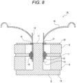
- a speaker device 1A of the second embodiment will be described with reference to Fig. 8 .
- a main magnetic gap 13 is filled with a magnetic fluid 16 in the speaker device 1A of the second embodiment.
- stability of a vibration operation of a coil bobbin 14 increases when compared to an embodiment in which one magnetic gap is filled with the magnetic fluid 16.
- a speaker device 1B of the third embodiment will be described with reference to Fig. 9 .
- one magnetic circuit is provided in the speaker device 1B of the third embodiment. That is, a magnetic circuit is formed on a front side of a support frame 41 made of a nonmagnetic material.
- a yoke 9 is configured only by a center pole portion 11 (this description is applied to a speaker device 1C to a speaker device 1G described below) .
- the speaker device 1B is similar to the above description in that two magnetic gaps corresponding to a main magnetic gap 13 and a sub-magnetic gap 21 are included inside the magnetic circuit, and the sub-magnetic gap 21 is filled with a magnetic fluid 16.
- the speaker device 1B has only one magnet 8.
- the speaker device 1B has a simple structure, and may be miniaturized.
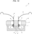
- the speaker device 1C of the fourth embodiment will be described with reference to Fig. 10 .
- a main magnetic gap 13 is filled with a magnetic fluid 16 in the speaker device 1C of the fourth embodiment.
- stability of a vibration operation of a coil bobbin 14 increases when compared to an embodiment in which one magnetic gap is filled with the magnetic fluid 16.
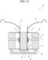
- the speaker device 1D of the fifth embodiment will be described with reference to Fig. 11 .
- a sub-magnetic gap 23 is provided in addition to a sub-magnetic gap 21 in the speaker device 1D of the fifth embodiment.
- the sub-magnetic gap 23 is formed between a sub-plate 24 and a yoke 9.
- the sub-magnetic gap 21 and the sub-magnetic gap 23 are formed on opposite sides of a voice coil 15, and a coil bobbin 14 is supported in the sub-magnetic gap 21 and the sub-magnetic gap 23.
- the coil bobbin 14 is more stably centered.
- the speaker device 1E of the sixth example will be described with reference to Fig. 12 .
- a sub-magnetic gap 21 is not filled with a magnetic fluid 16, and a main magnetic gap 13 is filled with the magnetic fluid 16 in the speaker device 1E of the sixth example.
- stability of a vibration operation of a coil bobbin 14 increases when compared to an embodiment in which one magnetic gap is filled with the magnetic fluid 16.
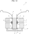
- the speaker device 1F of the seventh embodiment will be described with reference to Fig. 13 .
- a main magnetic gap 13 is filled with a magnetic fluid 16 in the speaker device 1F of the seventh embodiment. In this way, stability of a vibration operation of a coil bobbin 14 further increases.
- the speaker device 1G of the eighth example will be described with reference to Fig. 14 .
- positions of a sub-magnetic gap 21 and a main magnetic gap 13 are switched in the speaker device 1G of the eighth example. Then, a main plate 7 is attached to a front surface of a magnet 8, and a sub-plate 24 is attached to a rear surface of the magnet 8. A sub-magnetic gap 23 is filled with a magnetic fluid 16.
- the speaker device 1G has only one magnet 8. Thus, the speaker device 1G has a simple structure, and may be miniaturized.
- the speaker device 1H of the ninth embodiment will be described with reference to Fig. 15 .
- the speaker device 1H has magnets 8X and 8X, a yoke 9X, and a sub-plate 22X.
- a center portion of the yoke 9X is attached to a rear surface of a rear magnet 8X.
- the yoke 9X has a disc-shaped base surface portion 10X and a circumferential surface portion 11X that protrudes forward from an outer circumferential portion of the base surface portion 10X.
- the circumferential surface portion 11X includes a cylindrical portion 11a, a front flange portion 11b that projects inward from a front end portion of the cylindrical portion 11a, and a rear flange portion 11c that projects inward from a center portion of the cylindrical portion 11a in a front-rear direction.
- the magnets 8X and 8X are formed in disc shapes, and a main plate 7X made of a magnetic material is attached to a front surface of the rear magnet 8X.
- the main plate 7X is formed substantially in a disc shape having a thin thickness.
- a front magnet 8X is attached to a front surface of the main plate 7X.
- a sub-plate 22X made of a magnetic material is attached to a front surface of the front magnet 8X.
- the sub-plate 22X is formed substantially in a disc shape having a thin thickness .
- the main plate 7X, the sub-plate 22X, the magnets 8X and 8X, and the base surface portion 10X of the yoke 9X are combined with one another while central axes thereof are identical to one another.
- a space is formed between the main plate 7X and the rear flange portion 11c of the yoke 9X, and this space is formed as a main magnetic gap 13X.
- a space is formed between the sub-plate 22X and the front flange portion 11b of the yoke 9X, and this space is formed as a sub-magnetic gap 21X.
- a coil bobbin 14 is disposed on an outer circumferential side of the sub-plate 22X and the main plate 7X in a state in which the coil bobbin 14 is changeable (movable) in the front-rear direction. At least a portion of a voice coil 15 wound around the coil bobbin 14 is positioned in the main magnetic gap 13X, and respective portions of the coil bobbin 14 are positioned in the main magnetic gap 13X and the sub-magnetic gap 21X.
- a first magnetic circuit is configured by the main plate 7X, the rear flange portion 11c of the yoke 9X, the cylindrical portion 11a of the yoke 9X, the base surface portion 10X of the yoke 9X, and the rear magnet 8X.
- a second magnetic circuit is configured by the main plate 7X, the rear flange portion 11c of the yoke 9X, the cylindrical portion 11a of the yoke 9X, the front flange portion 11b of the yoke 9X, the sub-plate 22X, and the front magnet 8X.
- the sub-magnetic gap 21X is filled with a magnetic fluid 16.
- the voice coil 15 is positioned in the main magnetic gap 13X, and the sub-magnetic gap 21X is filled with a magnetic fluid 16.
- the magnetic fluid 16 is rarely scattered, and the amount of the filled magnetic fluid 16 rarely decreases. Further, a stable centering state of the coil bobbin 14 may be ensured.
- the speaker device 1I of the tenth embodiment will be described with reference to Fig. 16 .
- a main magnetic gap 13X is filled with a magnetic fluid 16 in the present embodiment.
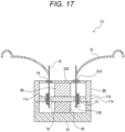
- the speaker device 1J of the eleventh embodiment will be described with reference to Fig. 17 .
- one magnetic circuit is provided in the present embodiment. That is, a columnar member 42 corresponding to a nonmagnetic material is attached to a front side of a center portion of a support frame 41. Further, a yoke 9X is attached to the front side of the support frame 41, and a main plate 7X is attached to a front side of the columnar member 42.
- a magnetic circuit is configured by including one magnet 8X, and thus cost is reduced.
- the speaker device 1K of the twelfth embodiment will be described with reference to Fig. 18 .
- a main magnetic gap 13X is filled with a magnetic fluid 16 in the present embodiment.
- the speaker device 1L of the thirteenth embodiment will be described with reference to Fig. 19 .
- one magnetic gap is added as a sub-magnetic gap 23, and the sub-magnetic gap 23 is filled with a magnetic fluid 16 in the present embodiment.
- a sub-plate 24 is attached to a front side of a support frame 41, and the sub-magnetic gap 23 is formed between the sub-plate 24 and a yoke 9X.
- a sub-magnetic gap 21X and the sub-magnetic gap 23 are filled with magnetic fluids 16 and 16, respectively.
- a coil bobbin 14 is more stably centered.
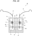
- the speaker device 1M of the fourteenth example will be described with reference to Fig. 20 .
- a sub-magnetic gap 21X is not filled with a magnetic fluid 16, and a main magnetic gap 13X is filled with the magnetic fluid 16 in the present example.
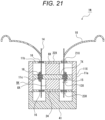
- the speaker device 1N of the fifteenth embodiment will be described with reference to Fig. 21 .
- a main magnetic gap 13X is filled with a magnetic fluid 16 in the present embodiment.
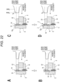
- Fig. 22A illustrates a case in which no gradient of a magnetic flux density is present in an amplitude direction of the sub-magnetic gap 21.
- a magnetic flux density distribution is nearly symmetric in the amplitude direction.
- Fig. 22B when the coil bobbin 14 changes in an X direction, the magnetic fluid 16 is easily scattered to the outside.
- a magnetic flux density distribution of the sub-magnetic gap 21 is asymmetric in the amplitude direction, and has a characteristic in that a gradient Ta is included as illustrated in Fig. 22C .
- a magnetic flux density is high near the inclined plane 12a, and the scattered magnetic fluid 16 is pulled to a side of the magnetic gap 21. Therefore, as illustrated in Fig. 22D , a return z is generated and pulled to the sub-magnetic gap 21, and scattering is suppressed.
- the magnetic flux change unit according to the modified examples illustrated below is formed in the sub-plate 22 or the center pole portion 11 of the yoke 19.
- description will be given of only different portions of the sub-plate 22 or the center pole portion 11.
- the same reference numeral as that of a similar portion in the speaker device 1 will be applied, and a description thereof will be omitted.
- a front end portion of a center pole portion 11A is positioned in a state in which the front end portion protrudes forward from a sub-plate 22, and the front end portion of the center pole portion 11A is provided as a magnetic flux change unit 12A according to a first modified example.
- the magnetic flux change unit 12A is formed in a shape, a diameter of which decreases toward a front side, and an outer circumferential surface thereof is set as an inclined plane 12a.
- a front end portion of a center pole portion 11B is positioned in a state in which the front end portion protrudes forward from a sub-plate 22, and the front end portion of the center pole portion 11B is provided as a magnetic flux change unit 12B according to a second modified example.
- the magnetic flux change unit 12B is formed in a shape, a diameter of which decreases toward a front side, and an outer circumferential surface thereof is set as a curved surface 12b.
- a front surface of a center pole portion 11 is positioned between a front surface and a rear surface of a sub-plate 22. Therefore, a portion on a front end side of the sub-plate 22 is positioned on a front side from the front surface of the center pole portion 11, and the portion on the front end side of the sub-plate 22 is provided as a magnetic flux change unit 12C according to a third modified example.
- a front surface of a center pole portion 11 is positioned between a front surface and a rear surface of a sub-plate 22D. Therefore, a portion on a front end side of the sub-plate 22D is positioned on a front side from the front surface of the center pole portion 11, and the portion on the front end side of the sub-plate 22D is provided as a magnetic flux change unit 12D according to a fourth modified example.
- the magnetic flux change unit 12D is formed in a shape, a diameter of which decreases toward a front side, and an inner circumferential surface thereof is set as an inclined plane 12d that is displaced outward toward a front side.
- a front surface of a center pole portion 11 is positioned between a front surface and a rear surface of a sub-plate 22E. Therefore, a portion on a front end side of the sub-plate 22E is positioned on a front side from the front surface of the center pole portion 11, and the portion on the front end side of the sub-plate 22E is provided as a magnetic flux change unit 12E according to a fifth modified example.
- the magnetic flux change unit 12E is formed in a shape, a diameter of which decreases toward a front side, and an inner circumferential surface thereof is set as a curved surface 12e that is displaced outward toward a front side.
- a sixth modified example is configured by combining a center pole portion 11A with a sub-plate 22D.
- a front surface of the center pole portion 11A is positioned on the same plane as a front surface of the sub-plate 22D, and a magnetic flux change unit 12A and a magnetic flux change unit 12D are included.
- a seventh modified example is configured by combining a center pole portion 11B with a sub-plate 22E.
- a front surface of the center pole portion 11B is positioned on the same plane as a front surface of the sub-plate 22E, and a magnetic flux change unit 12B and a magnetic flux change unit 12E are included.
- a magnetic gradient may be easily formed after ensuring simplicity of a shape of the center pole portion 11A or the sub-plate 22D.
- a magnetic gradient may be easily formed after ensuring simplicity of a shape of the center pole portion 11B or the sub-plate 22E.
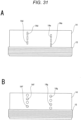
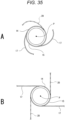
- Figs. 25A and 25B illustrate a cross-sectional structure of the sub-plate 22, the sub-magnetic gap 21, and the center pole portion 11.
- Fig. 25A illustrates a case in which there is no magnetic force gradient in the circumferential direction.
- the center pole portion 11 is located at a center position, and the sub-magnetic gap 21 and the sub-plate 22 are located around the center pole portion 11.
- Fig. 25B illustrates a case in which a magnetic force gradient is generated.
- magnetic flux change units 22a, 22a, and 22a are formed in the sub-plate 22.
- Fig. 26 is a graph illustrating a magnetic flux density of the sub-magnetic gap 21 in the circumferential direction.
- magnetic gradients (inclined portions) Sa, Sa, ... are formed by the magnetic flux change units 22a, 22a, and 22a, and magnetic forces are smaller than those of other portions.
- the magnetic gradient Sa indicates a change in magnetic flux density in which, even though a magnetic force is present, the magnetic force decreases toward a portion close to a center of the magnetic flux change unit 22a in the circumferential direction.
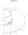
- the magnetic flux change units 22a, 22a, and 22a of the sub-plate 22 have functions of forming the magnetic gradients Sa, Sa, ... that change magnetic forces with respect to the magnetic fluid 16 by changing the magnetic flux density of the sub-magnetic gap 21 in the circumferential direction. Therefore, the magnetic fluid 16 filling the sub-magnetic gap 21 is held in a portion in which a magnetic flux density is high, and gaps 21a, 21a, and 21a in which the magnetic fluid 16 is not present are formed between the outer circumferential surface of the center pole portion 11 and the inner circumferential surface of the sub-plate 22 in the portions in which the magnetic flux change units 22a, 22a, and 22a are formed, respectively (see Fig. 27 ).
- the magnetic flux change unit 12 (12A, 12B, ...) is formed in the center pole portion 11 of the yoke 9.
- the magnetic flux change unit 12 of the center pole portion 11 has a function of forming a magnetic gradient Ta that changes a magnetic force with respect to the magnetic fluid 16 by changing a magnetic flux density in the axial direction, that is, a direction in which the coil bobbin 14 changes (see Figs. 22A to 22D ).
- a minimum value Samin of a magnetic flux density in the circumferential direction is larger than a value Tamid (see Fig. 22C ) corresponding to half a maximum value Tamax (see Fig. 22C ) of the magnetic flux density in the axial direction.
- portions 16a, 16a, ... of the magnetic fluid 16 to be likely to be scattered in the axial direction or the circumferential direction are pulled to the sub-magnetic gap 21 from the gaps 21a, 21a, and 21a corresponding to portions having magnetic forces in which the magnetic gradients Sa, Sa, ... are formed, and scattering is suppressed.
- the magnetic flux change unit according to the modified examples illustrated below is formed in the sub-plate or the center pole portion of the yoke.
- description will be given of only different portions of the sub-plate 22 or the center pole portion 11.
- the same reference numeral as that of a similar portion in the speaker device 1 will be applied, and a description thereof will be omitted.
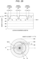
- Fig. 28 for example, six depressions separated from one another at equal intervals in a circumferential direction are formed on an inner circumferential surface of a sub-plate 22A, and the respective depressions are formed as magnetic flux change units 22a, 22a, ... according to a first modified example.
- the respective magnetic flux change units 22a, 22a, ... are formed while extending in a front-rear direction.
- An arbitrary number of magnetic flux change units 22a may be provided. Five or fewer magnetic flux change units 22a may be provided or seven or more magnetic flux change units 22a may be provided.
- a cross-sectional shape of each magnetic flux change unit 22a perpendicular to an axial direction is formed in a substantially semicircular shape.
- the cross-sectional shape may be formed in another shape such as a triangular shape, a quadrangular shape, and the like.
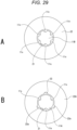
- Fig. 29A for example, six depressions separated from one another at equal intervals in a circumferential direction are formed on an outer circumferential surface of a center pole portion 11B, and the respective depressions are formed as magnetic flux change units 11x, 11x, ... according to a second modified example.
- the respective magnetic flux change units 11x, 11x, ... are formed while extending in a front-rear direction. Any magnetic flux change unit is not formed in a sub-plate 22.
- An arbitrary number of magnetic flux change units 11x may be provided. Five or fewer magnetic flux change units 11x may be provided or seven or more magnetic flux change units 11x may be provided.
- a cross-sectional shape of each magnetic flux change unit 11x perpendicular to an axial direction is formed in a substantially semicircular shape.
- the cross-sectional shape may be formed in another shape such as a triangular shape, a quadrangular shape, and the like.
- a third modified example is configured by combining the sub-plate 22A with the center pole portion 11A.
- the third modified example includes magnetic flux change units 22a, 22a, and 22a formed to be separated from one another at equal intervals in a circumferential direction, and magnetic flux change units 11x, 11x, and 11x formed to be separated from one another at equal intervals in the circumferential direction.
- the magnetic flux change units 22a, 22a, and 22a and the magnetic flux change units 11x, 11x, and 11x are alternately positioned in the circumferential direction.
- An arbitrary number of magnetic flux change units 22a and an arbitrary number of magnetic flux change units 11x may be provided. Two or fewer magnetic flux change units 22a and two or fewer magnetic flux change units 11x may be provided. In addition, four or more magnetic flux change units 22a and four or more magnetic flux change units 11x may be provided.
- a cross-sectional shape of each of the magnetic flux change unit 22a and the magnetic flux change unit 11x perpendicular to an axial direction is formed in a substantially semicircular shape.
- the cross-sectional shape may be formed in another shape such as a triangular shape, a quadrangular shape, and the like.
- the magnetic flux change units 22a, 22a, ... or a plurality of magnetic flux change units 11x, 11x, ... are symmetric.
- an excellent magnetic balance may be ensured, and the coil bobbin 14 may be smoothly displaced.
- depressions extending in the axial direction are formed as the magnetic flux change units 22a, 22a, ... and the magnetic flux change units 11x, 11x, ....
- the magnetic flux change units 11x, 11x, ... and the magnetic flux change units 11x, 11x, ... may be easily formed, and miniaturization of the speaker device 1 may be attempted without increase in an external diameter of the speaker device 1.
- the through-holes 14a, 14a, ... formed in the coil bobbin 14 are preferably formed at positions that allow a flow of the magnetic fluid 16 between the sub-plate 22 and the center pole portion 11 in a range of a variation in the axial direction toward the coil bobbin 14.
- the allowing positions refer to positions at which the through-holes 14a, 14a, ... are present at positions at which the magnetic fluid 16 is present at all times even when the coil bobbin 14 changes in the axial direction.
- the magnetic fluid 16 flows between the sub-plate 22 and the center pole portion 11 of the yoke 9 through the through-hole 14a. Therefore, excellent fluidity of the magnetic fluid 16 may be ensured, and thus accuracy of centering of the coil bobbin 14 may be improved, distortion of an input may be sufficiently reduced, and a stable signal reproduction operation may be ensured.
- Shapes of the through-holes 14a, 14a, ... may correspond to a shape such as a round shape, an angular, a slit shape, a curved slit shape, and the like.
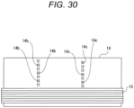
- a plurality of through-holes 14b, 14b, ... separated from one another at equal intervals and a plurality of through-holes 14c, 14c, ... separated from one another at equal intervals are positioned in an axial direction of a coil bobbin 14, and the through-holes 14b, 14b, ... are formed to be shifted from the through-holes 14c, 14c, ... in the axial direction.
- the through-holes 14b, 14b, ... and the through-holes 14c, 14c, ... are formed in rectangular shapes.
- the through-holes 14b, 14b, ... are formed to be shifted from the through-holes 14c, 14c, ... in the axial direction, at least one of the through-holes 14b, 14b, ... or the through-holes 14c, 14c, ... is located at a position at which the magnetic fluid 16 is present, and thus the magnetic fluid 16 more easily flows.
- a plurality of through-holes 14d, 14d, ... separated from one another at equal intervals and a plurality of through-holes 14e, 14e, ... separated from one another at equal intervals are positioned in an axial direction of a coil bobbin 14, the through-holes 14d, 14d, ... are formed to be shifted from the through-holes 14e, 14e, ... in the axial direction, and the through-holes 14d, 14d, ... and the through-holes 14e, 14e, ... are formed in slit shapes that extend in the axial direction.
- the through-holes 14d, 14d, ... and the through-holes 14e, 14e, ... are formed in the slit shapes that extend in the axial direction, and thus a magnetic fluid 16 more easily flows through either the through-holes 14d, 14d, ... or the through-holes 14e, 14e, ... when the coil bobbin 14 is changed in the axial direction.
- a plurality of through-holes 14f, 14f, ... separated from one another at equal intervals and a plurality of through-holes 14g, 14g, ... separated from one another at equal intervals are positioned in an axial direction of a coil bobbin 14, the through-holes 14f, 14f, ... are formed to be shifted from the through-holes 14g, 14g, ... in the axial direction, and the through-holes 14f, 14f, ... and the through-holes 14g, 14g, ... are formed in circular shapes.
- a magnetic fluid 16 easily flows through either the through-holes 14f, 14f, ... or the through-holes 14g, 14g, ....
- the through-holes 14f, 14f, ... and the through-holes 14g, 14g, ... are formed in the circular shapes, stress concentration rarely occurs at opening edges of the through-holes 14f, 14f, ... and the through-holes 14g, 14g, ..., and a high rigidity of the coil bobbin 14 may be ensured.
- Fig. 32A is a conceptual diagram illustrating a configuration of the speaker device 1 on which the support ring 25 is not installed
- Fig. 32B is a conceptual diagram illustrating a configuration of the speaker device 1 on which the support ring 25 is installed.
- the coil bobbin 14 When the coil bobbin 14 is installed in assembly of the speaker device 1, the coil bobbin 14 is installed by being inserted into the sub-plate 22 from a front side of the speaker device 1.
- a radius of a center portion of the sub-plate 22 is larger than an outer circumference (external diameter) of the voice coil 15. In this way, the voice coil 15 may smoothly pass through the sub-magnetic gap 21 which is formed on an inner circumferential side of the sub-plate 22.
- the sub-magnetic gap 21 may be made small by attaching the support ring 25 to an inner circumferential portion of the sub-plate 22 after the coil bobbin 14 is inserted into the center hole of the sub-plate 22.
- the support ring 25 is preferably made of a magnetic material.
- a value of a magnetic flux density of the sub-magnetic gap 21 may be increased to a peak value 40 (see Fig. 33 ).
- a peak value 39 illustrated in Fig. 33 is a value of a magnetic flux density of the main magnetic gap 13.
- the support ring 25 may be made of a nonmagnetic material. In this case, even though there is no effect that a magnetic flux density is increased, stability of centering effect of the coil bobbin 14 may be improved, and the amount of the filled magnetic fluid 16 may be reduced.
- the both end portions of the voice coil 15 are connected to the terminals 6 and 6 by the lead wires 17 and 17, respectively (see Fig. 2 ) .
- the lead wires 17 and 17 are attached to the coil bobbin 14 while being symmetrically disposed about the central axis P of the coil bobbin 14.
- the lead wires 17 and 17 are disposed in linear shapes.
- An arbitrary number of lead wires 17 may be provided when a plurality of lead wires 17 is provided, and three or more lead wires 17 may be provided.
- two lead wires 17 and 17 are attached to a coil bobbin 14 while being symmetrically disposed about a central axis P of the coil bobbin 14 with respect to the coil bobbin 14, and the lead wires 17 and 17 are disposed in curved shapes.
- Three or more lead wires 17 may be disposed when the lead wires 17 are symmetrically disposed about the central axis P of the coil bobbin 14.
- two lead wires 17 and 17 and one connecting wire 20 are attached to a coil bobbin 14 while being disposed at equal angles (symmetrically) about a central axis P of the coil bobbin 14 with respect to the coil bobbin 14, and the lead wires 17 and 17 and the connecting wire 20 are disposedin linear shapes .
- the connecting wire 20 is formed using the same material as that of the lead wire 17, and both ends of the connecting wire 20 are attached to a frame 2 and the coil bobbin 14, respectively.
- the connecting wire 20 may have a function of supplying current to a voice coil 15.
- two lead wires 17 and 17 and one connecting wire 20 are attached to a coil bobbin 14 while being disposed at equal angles (symmetrically) about a central axis P of the coil bobbin 14 with respect to the coil bobbin 14, and the lead wires 17 and 17 and the connecting wire 20 are disposed in curved shapes.
- the connecting wire 20 is formed using the same material as that of the lead wire 17, and both ends of the connecting wire 20 are attached to a frame 2 and the coil bobbin 14, respectively.
- the connecting wire 20 may have a function of supplying current to a voice coil 15.
- two lead wires 17 and 17 and two connecting wires 20 and 20 are attached to a coil bobbin 14 while being disposed at equal angles about a central axis P of the coil bobbin 14 with respect to the coil bobbin 14, and the lead wires 17 and 17 and the connecting wires 20 and 20 are disposed in linear shapes.
- the connecting wire 20 is formed using the same material as that of the lead wire 17, and both ends of the connecting wire 20 are attached to a frame 2 and the coil bobbin 14, respectively.
- the connecting wire 20 may have a function of supplying current to a voice coil 15.
- three or more connecting wires 20 may be disposed when the connecting wires 20 and the lead wires 17 and 17 are symmetrically disposed about the central axis P of the coil bobbin 14 with respect to the coil bobbin 14.
- two lead wires 17 and 17 and two connecting wires 20 and 20 are attached to a coil bobbin 14 while being disposed at equal angles about a central axis P of the coil bobbin 14 with respect to the coil bobbin 14, and the lead wires 17 and 17 and the connecting wires 20 and 20 are disposed in curved shapes.
- the connecting wire 20 is formed using the same material as that of the lead wire 17, and both ends of the connecting wire 20 are attached to a frame 2 and the coil bobbin 14, respectively.
- the connecting wire 20 may have a function of supplying current to a voice coil 15.
- three or more connecting wires 20 may be disposed when the connecting wires 20 and the lead wires 17 and 17 are symmetrically disposed about the central axis P of the coil bobbin 14 with respect to the coil bobbin 14.
- the sub-magnetic gap 21 and the main magnetic gap 13 are formed, and the sub-magnetic gap 21 is filled with the magnetic fluid 16 to hold the coil bobbin 14.
- the through-hole 14a is formed in the coil bobbin 14.
- the magnetic fluid 16 easily flows in the sub-magnetic gap 21, agitation thereof is suppressed, and centering effect that holds the coil bobbin 14 in a center position inside the sub-magnetic gap 21 is stable. Further, it is possible to attempt improvement in acoustic conversion efficiency and improvement in sound quality.
- a magnetic gradient is formed to change a magnetic force with respect to the magnetic fluid 16 by changing a magnetic flux density in the circumferential direction of the center pole portion 11.
- the magnetic fluid 16 is not scattered from the sub-magnetic gap 21, and the amount of the magnetic fluid 16 filling the sub-magnetic gap 21 is not reduced.
- the magnetic fluid 16 is not agitated, and thus it is possible to attempt improvement in acoustic conversion efficiency and improvement in sound quality.
- a magnetic gradient that changes a magnetic force with respect to the magnetic fluid 16 by changing a magnetic flux density is formed in the axial direction of the center pole portion 11.
- a minimum value Samin of a magnetic flux density in the circumferential direction is larger than a value corresponding to half a maximum value Tamax of the magnetic flux density in the axial direction.
- a saturated magnetic flux of the magnetic fluid 16 is set to 30 mT to 40 mT, and a viscosity of the magnetic fluid 16 is set to 300 cp or less.
- the magnetic flux change units 22a, 22a, ... or the magnetic flux change units 11x, 11x, ..., which form a magnetic gradient in the circumferential direction of the center pole portion 11, are formed on the inner circumferential surface of the sub-plates 22 and 22A or the outer circumferential surface of the center pole portions 11A and 11B, structures of the sub-plates 22 and 22A and the center pole portions 11A and 11B are not complicated, and it is possible to attempt improvement in acoustic conversion efficiency and improvement in sound quality after ensuring simplified structures.
- the magnetic flux change units 12, 12A, and 12B or the magnetic flux change units 12C, 12D, and 12E, which form magnetic gradients in the axial direction of the center pole portions 11, 11A, and 11B, are formed on the sub-plates 22, 22D, and 22E or in the center pole portions 11, 11A, and 11B, structures of the sub-plates 22, 22D, and 22E or the center pole portions 11, 11A, and 11B are not complicated, and it is possible to attempt improvement in acoustic conversion efficiency and improvement in sound quality after ensuring simplified structures.
- the magnetic flux change units 12, 12A, 12B, 12C, 12D, and 12E are provided by causing distal end portions of the center pole portions 11, 11A, and 11B to protrude in the axial direction from the sub-plate 22 or disposing the front surface of the center pole portion 11 on rear sides of the front surfaces of the sub-plates 22, 22D, and 22E, the magnetic flux change units 12, 12A, 12B, 12C, 12D, and 12E may be easily provided.
- the main magnetic gap 13 is preferably positioned on a side of the vibration plate 18 from the sub-magnetic gap 21.
- the voice coil 15 is positioned on a side of the vibration plate 18.
- the sub-magnetic gap 21 may not be made large to prepare for assembly (insertion) of the coil bobbin 14, and improvement in magnetic flux density may be attempted.
Landscapes
- Engineering & Computer Science (AREA)
- Physics & Mathematics (AREA)
- Acoustics & Sound (AREA)
- Signal Processing (AREA)
- Multimedia (AREA)
- Audible-Bandwidth Dynamoelectric Transducers Other Than Pickups (AREA)
Claims (13)
- Dispositif haut-parleur (1), comprenant :un aimant (8) pourvu d'un axe central ;une culasse (9) pourvue d'un axe central, l'axe central de la culasse étant identique à l'axe central de l'aimant, l'aimant (8) étant fixé à la culasse (9) ;une plaque principale (7) fixée à l'aimant ;au moins une sous-plaque (22) fixée à l'aimant, positionnée pour être séparée de la plaque principale dans une direction axiale de l'axe central et pourvue d'un trou central défini par une surface circonférentielle intérieure ;une armature de bobine (14) dotée d'une forme tubulaire et mobile dans la direction axiale de l'axe central ;une bobine mobile (15) enroulée autour d'une surface circonférentielle extérieure de l'armature de bobine (14), au moins une partie de la bobine mobile (15) étant placée dans un entrefer magnétique principal (13) ménagé entre la plaque principale (7) et la culasse (9) ;une plaque vibrante (18) pourvue d'une partie circonférentielle intérieure reliée à l'armature de bobine (14), et vibrant en fonction d'un mouvement de l'armature de bobine (14) ; etun fluide magnétique (16) remplissant au moins un sous-entrefer magnétique (21) ménagé entre la sous-plaque (22) et la culasse (9),l'armature de bobine (14) et la bobine mobile (15) étant situées à l'intérieur du trou central de la sous-plaque (22),un trou traversant (14a) positionné dans le sous-entrefer magnétique (21) rempli du fluide magnétique (16) étant ménagé dans l'armature de bobine (14),caractérisé en ce que :le sous-entrefer magnétique (21) est positionné de telle manière que la plaque vibrante (18) et le sous-entrefer magnétique (21) se trouvent d'un même côté de l'entrefer magnétique principal (13),une bague de support (25) est fixée à une partie de la surface circonférentielle intérieure de la sous-plaque (22), etau moins une partie de la bague de support (25) est positionnée à l'intérieur de la surface circonférentielle intérieure de la sous-plaque (22).
- Dispositif haut-parleur selon la revendication 1, dans lequel la bague de support est formée d'une substance magnétique.
- Dispositif haut-parleur selon la revendication 1, dans lequel un gradient magnétique est formé pour faire varier une force magnétique par rapport au fluide magnétique en faisant varier une densité de flux magnétique dans la direction axiale.
- Dispositif haut-parleur selon la revendication 1, dans lequel un gradient magnétique est formé pour faire varier une force magnétique par rapport au fluide magnétique en faisant varier une densité de flux magnétique dans une direction circonférentielle de l'axe central.
- Dispositif haut-parleur selon la revendication 1,dans lequel une pluralité de trous traversants sont ménagés de manière à être séparés les uns des autres dans une direction circonférentielle de l'armature de bobine, etles positions de la pluralité de trous traversants sont décalées dans la direction axiale.
- Dispositif haut-parleur selon la revendication 1,dans lequel le trou traversant prend la forme d'une fente s'étendant dans la direction axiale de l'armature de bobine, et une pluralité de trous traversants sont ménagés de manière à être séparés les uns des autres dans une direction circonférentielle de l'armature de bobine, etles positions de la pluralité de trous traversants sont décalées dans la direction axiale.
- Dispositif haut-parleur selon la revendication 4, dans lequel une unité de variation de flux magnétique formant le gradient magnétique dans la direction axiale est contenue dans la sous-plaque ou la culasse.
- Dispositif haut-parleur selon la revendication 7, dans lequel une partie extrémité distale de la culasse est amenée à faire saillie de la sous-plaque dans la direction axiale, et la partie extrémité distale joue le rôle de l'unité de variation de flux magnétique.
- Dispositif haut-parleur selon la revendication 7, dans lequel un plan incliné, qui est incliné dans la direction axiale, est formé sur une surface de la sous-plaque ou de la culasse, et une partie sur laquelle est formé le plan incliné joue le rôle de l'unité de variation de flux magnétique.
- Dispositif haut-parleur selon la revendication 7, dans lequel une surface incurvée est formée sur une surface de la sous-plaque ou de la culasse, et une partie sur laquelle est formée la surface incurvée joue le rôle de l'unité de variation de flux magnétique.
- Dispositif haut-parleur selon la revendication 4, dans lequel une unité de variation de flux magnétique formant le gradient magnétique dans la direction axiale est contenue dans la sous-plaque et la culasse.
- Dispositif haut-parleur selon la revendication 11, dans lequel un plan incliné, qui est incliné dans la direction axiale, est formé sur des surfaces respectives de la sous-plaque et de la culasse, et des parties respectives sur lesquelles est formé le plan incliné jouent le rôle de l'unité de variation de flux magnétique.
- Dispositif haut-parleur selon la revendication 11, dans lequel une surface incurvée est formée sur une surface de la sous-plaque ou de la culasse, et une partie sur laquelle est formée la surface incurvée joue le rôle de l'unité de variation de flux magnétique.
Applications Claiming Priority (2)
| Application Number | Priority Date | Filing Date | Title |
|---|---|---|---|
| JP2014013523 | 2014-01-28 | ||
| PCT/JP2015/050914 WO2015115191A1 (fr) | 2014-01-28 | 2015-01-15 | Dispositif de haut-parleur |
Publications (3)
| Publication Number | Publication Date |
|---|---|
| EP3073763A1 EP3073763A1 (fr) | 2016-09-28 |
| EP3073763A4 EP3073763A4 (fr) | 2017-11-22 |
| EP3073763B1 true EP3073763B1 (fr) | 2023-06-07 |
Family
ID=53756768
Family Applications (1)
| Application Number | Title | Priority Date | Filing Date |
|---|---|---|---|
| EP15743795.5A Active EP3073763B1 (fr) | 2014-01-28 | 2015-01-15 | Dispositif de haut-parleur |
Country Status (5)
| Country | Link |
|---|---|
| US (1) | US10111007B2 (fr) |
| EP (1) | EP3073763B1 (fr) |
| JP (1) | JP6497324B2 (fr) |
| CN (1) | CN105850152B (fr) |
| WO (1) | WO2015115191A1 (fr) |
Families Citing this family (8)
| Publication number | Priority date | Publication date | Assignee | Title |
|---|---|---|---|---|
| KR102452632B1 (ko) | 2015-08-17 | 2022-10-07 | 삼성전자주식회사 | 운동 보조 장치 및 그 제어 방법 |
| KR20170114471A (ko) | 2016-04-05 | 2017-10-16 | 엘지디스플레이 주식회사 | 유기발광 표시 장치 |
| KR102663406B1 (ko) | 2016-04-04 | 2024-05-14 | 엘지디스플레이 주식회사 | 패널 진동형 음향 발생 액츄에이터 및 그를 포함하는 양면 표시 장치 |
| US10129646B2 (en) * | 2016-03-28 | 2018-11-13 | Lg Display Co., Ltd. | Panel vibration type sound generating display device |
| KR101704517B1 (ko) | 2016-03-28 | 2017-02-09 | 엘지디스플레이 주식회사 | 패널 진동형 음향 발생 표시 장치 |
| CN110235452B (zh) | 2017-02-06 | 2021-12-24 | 索尼公司 | 扬声器振动板和扬声器装置 |
| GB201907610D0 (en) * | 2019-05-29 | 2019-07-10 | Pss Belgium Nv | Loudspeaker |
| JP7849512B2 (ja) * | 2023-12-06 | 2026-04-21 | ゴーアテック インコーポレイテッド | 放音装置、放音モジュール及び電子機器 |
Citations (1)
| Publication number | Priority date | Publication date | Assignee | Title |
|---|---|---|---|---|
| EP1274275A1 (fr) * | 2001-02-13 | 2003-01-08 | Matsushita Electric Industrial Co., Ltd. | Haut-parleur |
Family Cites Families (9)
| Publication number | Priority date | Publication date | Assignee | Title |
|---|---|---|---|---|
| JPS5942691U (ja) * | 1982-09-10 | 1984-03-19 | パイオニア株式会社 | スピ−カ用磁気回路 |
| JPS5948197U (ja) * | 1982-09-21 | 1984-03-30 | 松下電器産業株式会社 | スピ−カ |
| DK171729B1 (da) * | 1994-11-01 | 1997-04-14 | Dan Kristoffersen | Elektrodynamisk højttaler med væskeophængt bevægeligt system |
| EP1420610A4 (fr) | 2001-07-23 | 2006-06-28 | Toshio Chikama | Protection magnetique de bobine de lecture de haut-parleur |
| US7006654B2 (en) * | 2003-02-07 | 2006-02-28 | Step Technologies, Inc. | Push-pull electromagnetic transducer with increased Xmax |
| US6865282B2 (en) * | 2003-05-01 | 2005-03-08 | Richard L. Weisman | Loudspeaker suspension for achieving very long excursion |
| JP2008118331A (ja) | 2006-11-02 | 2008-05-22 | Matsushita Electric Ind Co Ltd | スピーカ |
| US8009857B2 (en) * | 2007-02-15 | 2011-08-30 | Wisdom Audio Corp. | Induction motor for loudspeaker |
| JP5751090B2 (ja) | 2011-08-22 | 2015-07-22 | ソニー株式会社 | スピーカー装置 |
-
2015
- 2015-01-15 EP EP15743795.5A patent/EP3073763B1/fr active Active
- 2015-01-15 US US15/106,964 patent/US10111007B2/en active Active
- 2015-01-15 WO PCT/JP2015/050914 patent/WO2015115191A1/fr not_active Ceased
- 2015-01-15 CN CN201580003241.4A patent/CN105850152B/zh active Active
- 2015-01-15 JP JP2015559862A patent/JP6497324B2/ja active Active
Patent Citations (1)
| Publication number | Priority date | Publication date | Assignee | Title |
|---|---|---|---|---|
| EP1274275A1 (fr) * | 2001-02-13 | 2003-01-08 | Matsushita Electric Industrial Co., Ltd. | Haut-parleur |
Also Published As
| Publication number | Publication date |
|---|---|
| CN105850152B (zh) | 2019-11-01 |
| EP3073763A1 (fr) | 2016-09-28 |
| JPWO2015115191A1 (ja) | 2017-03-23 |
| CN105850152A (zh) | 2016-08-10 |
| WO2015115191A1 (fr) | 2015-08-06 |
| EP3073763A4 (fr) | 2017-11-22 |
| JP6497324B2 (ja) | 2019-04-10 |
| US20160345102A1 (en) | 2016-11-24 |
| US10111007B2 (en) | 2018-10-23 |
Similar Documents
| Publication | Publication Date | Title |
|---|---|---|
| EP3073763B1 (fr) | Dispositif de haut-parleur | |
| JP5751090B2 (ja) | スピーカー装置 | |
| CN106878884B (zh) | 多磁体扬声器 | |
| US9036839B2 (en) | Multi-way coaxial loudspeaker with magnetic cylinder | |
| CN102740197B (zh) | 扬声器磁体组件 | |
| US9100733B2 (en) | Multi-way coaxial loudspeaker with internal magnet motor and permanent magnet cylinder | |
| CN102740195B (zh) | 具有通道的扬声器磁体 | |
| JP6572453B2 (ja) | スピーカ装置 | |
| US20140056466A1 (en) | Loudspeaker driver with dual electromagnet assemblies | |
| US20200169797A1 (en) | Audio speaker with a voice coil assembly and a method of manufacturing the speaker | |
| CN110881161B (zh) | 扬声器及电子设备 | |
| CN112154675A (zh) | 具有多磁体结构的高效扬声器 | |
| JP2006005852A (ja) | スピーカー装置 | |
| JP4946765B2 (ja) | スピーカユニット | |
| US11350216B2 (en) | Speaker diaphragm and speaker apparatus | |
| JP2020150472A (ja) | スピーカユニット、電子機器および移動体装置 | |
| WO2013190811A1 (fr) | Dispositif de haut-parleur et dispositif équipé d'un haut-parleur | |
| JPWO2017104124A1 (ja) | 電気音響変換器 | |
| JP2019161325A (ja) | 電気音響変換器、移動体、および電子機器 | |
| JP2003179995A (ja) | スピーカの磁気回路 | |
| EP3952337A1 (fr) | Haut-parleur et procédé de fabrication de celui-ci | |
| WO2017104125A1 (fr) | Transducteur électro-acoustique | |
| JP2014003690A (ja) | スピーカ |
Legal Events
| Date | Code | Title | Description |
|---|---|---|---|
| PUAI | Public reference made under article 153(3) epc to a published international application that has entered the european phase |
Free format text: ORIGINAL CODE: 0009012 |
|
| 17P | Request for examination filed |
Effective date: 20160621 |
|
| AK | Designated contracting states |
Kind code of ref document: A1 Designated state(s): AL AT BE BG CH CY CZ DE DK EE ES FI FR GB GR HR HU IE IS IT LI LT LU LV MC MK MT NL NO PL PT RO RS SE SI SK SM TR |
|
| AX | Request for extension of the european patent |
Extension state: BA ME |
|
| DAX | Request for extension of the european patent (deleted) | ||
| A4 | Supplementary search report drawn up and despatched |
Effective date: 20171020 |
|
| RIC1 | Information provided on ipc code assigned before grant |
Ipc: H04R 9/02 20060101AFI20171016BHEP Ipc: H04R 9/04 20060101ALI20171016BHEP |
|
| STAA | Information on the status of an ep patent application or granted ep patent |
Free format text: STATUS: EXAMINATION IS IN PROGRESS |
|
| 17Q | First examination report despatched |
Effective date: 20210208 |
|
| RAP3 | Party data changed (applicant data changed or rights of an application transferred) |
Owner name: SONY GROUP CORPORATION |
|
| GRAP | Despatch of communication of intention to grant a patent |
Free format text: ORIGINAL CODE: EPIDOSNIGR1 |
|
| STAA | Information on the status of an ep patent application or granted ep patent |
Free format text: STATUS: GRANT OF PATENT IS INTENDED |
|
| INTG | Intention to grant announced |
Effective date: 20230109 |
|
| GRAS | Grant fee paid |
Free format text: ORIGINAL CODE: EPIDOSNIGR3 |
|
| GRAA | (expected) grant |
Free format text: ORIGINAL CODE: 0009210 |
|
| STAA | Information on the status of an ep patent application or granted ep patent |
Free format text: STATUS: THE PATENT HAS BEEN GRANTED |
|
| AK | Designated contracting states |
Kind code of ref document: B1 Designated state(s): AL AT BE BG CH CY CZ DE DK EE ES FI FR GB GR HR HU IE IS IT LI LT LU LV MC MK MT NL NO PL PT RO RS SE SI SK SM TR |
|
| REG | Reference to a national code |
Ref country code: GB Ref legal event code: FG4D |
|
| REG | Reference to a national code |
Ref country code: CH Ref legal event code: EP Ref country code: AT Ref legal event code: REF Ref document number: 1578273 Country of ref document: AT Kind code of ref document: T Effective date: 20230615 |
|
| REG | Reference to a national code |
Ref country code: DE Ref legal event code: R096 Ref document number: 602015083882 Country of ref document: DE |
|
| REG | Reference to a national code |
Ref country code: LT Ref legal event code: MG9D |
|
| REG | Reference to a national code |
Ref country code: NL Ref legal event code: MP Effective date: 20230607 |
|
| PG25 | Lapsed in a contracting state [announced via postgrant information from national office to epo] |
Ref country code: SE Free format text: LAPSE BECAUSE OF FAILURE TO SUBMIT A TRANSLATION OF THE DESCRIPTION OR TO PAY THE FEE WITHIN THE PRESCRIBED TIME-LIMIT Effective date: 20230607 Ref country code: NO Free format text: LAPSE BECAUSE OF FAILURE TO SUBMIT A TRANSLATION OF THE DESCRIPTION OR TO PAY THE FEE WITHIN THE PRESCRIBED TIME-LIMIT Effective date: 20230907 Ref country code: ES Free format text: LAPSE BECAUSE OF FAILURE TO SUBMIT A TRANSLATION OF THE DESCRIPTION OR TO PAY THE FEE WITHIN THE PRESCRIBED TIME-LIMIT Effective date: 20230607 |
|
| REG | Reference to a national code |
Ref country code: AT Ref legal event code: MK05 Ref document number: 1578273 Country of ref document: AT Kind code of ref document: T Effective date: 20230607 |
|
| PG25 | Lapsed in a contracting state [announced via postgrant information from national office to epo] |
Ref country code: RS Free format text: LAPSE BECAUSE OF FAILURE TO SUBMIT A TRANSLATION OF THE DESCRIPTION OR TO PAY THE FEE WITHIN THE PRESCRIBED TIME-LIMIT Effective date: 20230607 Ref country code: NL Free format text: LAPSE BECAUSE OF FAILURE TO SUBMIT A TRANSLATION OF THE DESCRIPTION OR TO PAY THE FEE WITHIN THE PRESCRIBED TIME-LIMIT Effective date: 20230607 Ref country code: LV Free format text: LAPSE BECAUSE OF FAILURE TO SUBMIT A TRANSLATION OF THE DESCRIPTION OR TO PAY THE FEE WITHIN THE PRESCRIBED TIME-LIMIT Effective date: 20230607 Ref country code: LT Free format text: LAPSE BECAUSE OF FAILURE TO SUBMIT A TRANSLATION OF THE DESCRIPTION OR TO PAY THE FEE WITHIN THE PRESCRIBED TIME-LIMIT Effective date: 20230607 Ref country code: HR Free format text: LAPSE BECAUSE OF FAILURE TO SUBMIT A TRANSLATION OF THE DESCRIPTION OR TO PAY THE FEE WITHIN THE PRESCRIBED TIME-LIMIT Effective date: 20230607 Ref country code: GR Free format text: LAPSE BECAUSE OF FAILURE TO SUBMIT A TRANSLATION OF THE DESCRIPTION OR TO PAY THE FEE WITHIN THE PRESCRIBED TIME-LIMIT Effective date: 20230908 |
|
| PG25 | Lapsed in a contracting state [announced via postgrant information from national office to epo] |
Ref country code: FI Free format text: LAPSE BECAUSE OF FAILURE TO SUBMIT A TRANSLATION OF THE DESCRIPTION OR TO PAY THE FEE WITHIN THE PRESCRIBED TIME-LIMIT Effective date: 20230607 |
|
| PG25 | Lapsed in a contracting state [announced via postgrant information from national office to epo] |
Ref country code: SK Free format text: LAPSE BECAUSE OF FAILURE TO SUBMIT A TRANSLATION OF THE DESCRIPTION OR TO PAY THE FEE WITHIN THE PRESCRIBED TIME-LIMIT Effective date: 20230607 |
|
| PG25 | Lapsed in a contracting state [announced via postgrant information from national office to epo] |
Ref country code: IS Free format text: LAPSE BECAUSE OF FAILURE TO SUBMIT A TRANSLATION OF THE DESCRIPTION OR TO PAY THE FEE WITHIN THE PRESCRIBED TIME-LIMIT Effective date: 20231007 |
|
| PG25 | Lapsed in a contracting state [announced via postgrant information from national office to epo] |
Ref country code: SM Free format text: LAPSE BECAUSE OF FAILURE TO SUBMIT A TRANSLATION OF THE DESCRIPTION OR TO PAY THE FEE WITHIN THE PRESCRIBED TIME-LIMIT Effective date: 20230607 Ref country code: SK Free format text: LAPSE BECAUSE OF FAILURE TO SUBMIT A TRANSLATION OF THE DESCRIPTION OR TO PAY THE FEE WITHIN THE PRESCRIBED TIME-LIMIT Effective date: 20230607 Ref country code: RO Free format text: LAPSE BECAUSE OF FAILURE TO SUBMIT A TRANSLATION OF THE DESCRIPTION OR TO PAY THE FEE WITHIN THE PRESCRIBED TIME-LIMIT Effective date: 20230607 Ref country code: PT Free format text: LAPSE BECAUSE OF FAILURE TO SUBMIT A TRANSLATION OF THE DESCRIPTION OR TO PAY THE FEE WITHIN THE PRESCRIBED TIME-LIMIT Effective date: 20231009 Ref country code: IS Free format text: LAPSE BECAUSE OF FAILURE TO SUBMIT A TRANSLATION OF THE DESCRIPTION OR TO PAY THE FEE WITHIN THE PRESCRIBED TIME-LIMIT Effective date: 20231007 Ref country code: EE Free format text: LAPSE BECAUSE OF FAILURE TO SUBMIT A TRANSLATION OF THE DESCRIPTION OR TO PAY THE FEE WITHIN THE PRESCRIBED TIME-LIMIT Effective date: 20230607 Ref country code: CZ Free format text: LAPSE BECAUSE OF FAILURE TO SUBMIT A TRANSLATION OF THE DESCRIPTION OR TO PAY THE FEE WITHIN THE PRESCRIBED TIME-LIMIT Effective date: 20230607 Ref country code: AT Free format text: LAPSE BECAUSE OF FAILURE TO SUBMIT A TRANSLATION OF THE DESCRIPTION OR TO PAY THE FEE WITHIN THE PRESCRIBED TIME-LIMIT Effective date: 20230607 |
|
| PGFP | Annual fee paid to national office [announced via postgrant information from national office to epo] |
Ref country code: FR Payment date: 20231219 Year of fee payment: 10 |
|
| PG25 | Lapsed in a contracting state [announced via postgrant information from national office to epo] |
Ref country code: PL Free format text: LAPSE BECAUSE OF FAILURE TO SUBMIT A TRANSLATION OF THE DESCRIPTION OR TO PAY THE FEE WITHIN THE PRESCRIBED TIME-LIMIT Effective date: 20230607 |
|
| REG | Reference to a national code |
Ref country code: DE Ref legal event code: R097 Ref document number: 602015083882 Country of ref document: DE |
|
| PLBE | No opposition filed within time limit |
Free format text: ORIGINAL CODE: 0009261 |
|
| STAA | Information on the status of an ep patent application or granted ep patent |
Free format text: STATUS: NO OPPOSITION FILED WITHIN TIME LIMIT |
|
| PG25 | Lapsed in a contracting state [announced via postgrant information from national office to epo] |
Ref country code: DK Free format text: LAPSE BECAUSE OF FAILURE TO SUBMIT A TRANSLATION OF THE DESCRIPTION OR TO PAY THE FEE WITHIN THE PRESCRIBED TIME-LIMIT Effective date: 20230607 |
|
| PG25 | Lapsed in a contracting state [announced via postgrant information from national office to epo] |
Ref country code: SI Free format text: LAPSE BECAUSE OF FAILURE TO SUBMIT A TRANSLATION OF THE DESCRIPTION OR TO PAY THE FEE WITHIN THE PRESCRIBED TIME-LIMIT Effective date: 20230607 |
|
| 26N | No opposition filed |
Effective date: 20240308 |
|
| PG25 | Lapsed in a contracting state [announced via postgrant information from national office to epo] |
Ref country code: SI Free format text: LAPSE BECAUSE OF FAILURE TO SUBMIT A TRANSLATION OF THE DESCRIPTION OR TO PAY THE FEE WITHIN THE PRESCRIBED TIME-LIMIT Effective date: 20230607 Ref country code: IT Free format text: LAPSE BECAUSE OF FAILURE TO SUBMIT A TRANSLATION OF THE DESCRIPTION OR TO PAY THE FEE WITHIN THE PRESCRIBED TIME-LIMIT Effective date: 20230607 |
|
| PG25 | Lapsed in a contracting state [announced via postgrant information from national office to epo] |
Ref country code: MC Free format text: LAPSE BECAUSE OF FAILURE TO SUBMIT A TRANSLATION OF THE DESCRIPTION OR TO PAY THE FEE WITHIN THE PRESCRIBED TIME-LIMIT Effective date: 20230607 |
|
| PG25 | Lapsed in a contracting state [announced via postgrant information from national office to epo] |
Ref country code: MC Free format text: LAPSE BECAUSE OF FAILURE TO SUBMIT A TRANSLATION OF THE DESCRIPTION OR TO PAY THE FEE WITHIN THE PRESCRIBED TIME-LIMIT Effective date: 20230607 |
|
| REG | Reference to a national code |
Ref country code: CH Ref legal event code: PL |
|
| PG25 | Lapsed in a contracting state [announced via postgrant information from national office to epo] |
Ref country code: LU Free format text: LAPSE BECAUSE OF NON-PAYMENT OF DUE FEES Effective date: 20240115 |
|
| PG25 | Lapsed in a contracting state [announced via postgrant information from national office to epo] |
Ref country code: LU Free format text: LAPSE BECAUSE OF NON-PAYMENT OF DUE FEES Effective date: 20240115 |
|
| PG25 | Lapsed in a contracting state [announced via postgrant information from national office to epo] |
Ref country code: BE Free format text: LAPSE BECAUSE OF NON-PAYMENT OF DUE FEES Effective date: 20240131 |
|
| PG25 | Lapsed in a contracting state [announced via postgrant information from national office to epo] |
Ref country code: CH Free format text: LAPSE BECAUSE OF NON-PAYMENT OF DUE FEES Effective date: 20240131 |
|
| PG25 | Lapsed in a contracting state [announced via postgrant information from national office to epo] |
Ref country code: CH Free format text: LAPSE BECAUSE OF NON-PAYMENT OF DUE FEES Effective date: 20240131 Ref country code: BE Free format text: LAPSE BECAUSE OF NON-PAYMENT OF DUE FEES Effective date: 20240131 |
|
| REG | Reference to a national code |
Ref country code: BE Ref legal event code: MM Effective date: 20240131 |
|
| PG25 | Lapsed in a contracting state [announced via postgrant information from national office to epo] |
Ref country code: BG Free format text: LAPSE BECAUSE OF FAILURE TO SUBMIT A TRANSLATION OF THE DESCRIPTION OR TO PAY THE FEE WITHIN THE PRESCRIBED TIME-LIMIT Effective date: 20230607 |
|
| PG25 | Lapsed in a contracting state [announced via postgrant information from national office to epo] |
Ref country code: BG Free format text: LAPSE BECAUSE OF FAILURE TO SUBMIT A TRANSLATION OF THE DESCRIPTION OR TO PAY THE FEE WITHIN THE PRESCRIBED TIME-LIMIT Effective date: 20230607 |
|
| PGFP | Annual fee paid to national office [announced via postgrant information from national office to epo] |
Ref country code: GB Payment date: 20241219 Year of fee payment: 11 |
|
| PG25 | Lapsed in a contracting state [announced via postgrant information from national office to epo] |
Ref country code: IE Free format text: LAPSE BECAUSE OF NON-PAYMENT OF DUE FEES Effective date: 20240115 |
|
| PG25 | Lapsed in a contracting state [announced via postgrant information from national office to epo] |
Ref country code: IE Free format text: LAPSE BECAUSE OF NON-PAYMENT OF DUE FEES Effective date: 20240115 |
|
| PGFP | Annual fee paid to national office [announced via postgrant information from national office to epo] |
Ref country code: DE Payment date: 20241218 Year of fee payment: 11 |
|
| PG25 | Lapsed in a contracting state [announced via postgrant information from national office to epo] |
Ref country code: CY Free format text: LAPSE BECAUSE OF FAILURE TO SUBMIT A TRANSLATION OF THE DESCRIPTION OR TO PAY THE FEE WITHIN THE PRESCRIBED TIME-LIMIT; INVALID AB INITIO Effective date: 20150115 |
|
| PG25 | Lapsed in a contracting state [announced via postgrant information from national office to epo] |
Ref country code: HU Free format text: LAPSE BECAUSE OF FAILURE TO SUBMIT A TRANSLATION OF THE DESCRIPTION OR TO PAY THE FEE WITHIN THE PRESCRIBED TIME-LIMIT; INVALID AB INITIO Effective date: 20150115 |
|
| PG25 | Lapsed in a contracting state [announced via postgrant information from national office to epo] |
Ref country code: FR Free format text: LAPSE BECAUSE OF NON-PAYMENT OF DUE FEES Effective date: 20250131 |
|
| PG25 | Lapsed in a contracting state [announced via postgrant information from national office to epo] |
Ref country code: TR Free format text: LAPSE BECAUSE OF FAILURE TO SUBMIT A TRANSLATION OF THE DESCRIPTION OR TO PAY THE FEE WITHIN THE PRESCRIBED TIME-LIMIT Effective date: 20230607 |