EP3074294B1 - Platte eines elektrischen schalters und lenksäule eines fahrzeugs - Google Patents
Platte eines elektrischen schalters und lenksäule eines fahrzeugs Download PDFInfo
- Publication number
- EP3074294B1 EP3074294B1 EP14806010.6A EP14806010A EP3074294B1 EP 3074294 B1 EP3074294 B1 EP 3074294B1 EP 14806010 A EP14806010 A EP 14806010A EP 3074294 B1 EP3074294 B1 EP 3074294B1
- Authority
- EP
- European Patent Office
- Prior art keywords
- plate
- steering column
- rotation locking
- locking elements
- rotation
- Prior art date
- Legal status (The legal status is an assumption and is not a legal conclusion. Google has not performed a legal analysis and makes no representation as to the accuracy of the status listed.)
- Active
Links
Images


Classifications
-
- B—PERFORMING OPERATIONS; TRANSPORTING
- B62—LAND VEHICLES FOR TRAVELLING OTHERWISE THAN ON RAILS
- B62D—MOTOR VEHICLES; TRAILERS
- B62D1/00—Steering controls, i.e. means for initiating a change of direction of the vehicle
- B62D1/02—Steering controls, i.e. means for initiating a change of direction of the vehicle vehicle-mounted
- B62D1/16—Steering columns
Definitions
- the invention relates to the attachment of an electrical switch plate on a steering column of a vehicle, especially automobile. More specifically, according to the invention, such a plate comprises a plurality of anti-rotation locking elements of the plate relative to the steering column.
- Such a switch is generally in the form of a housing mounted on the steering column of the vehicle.
- the housing comprises on its rear face a plate having an axially split shaft in which the steering column is inserted and which is then fixed on the column by means of a clamping collar.
- EP1 319 573 A discloses a module for attachment to a steering column of a vehicle by means of a fastener forming such a clamp.
- a known solution consists in adding an anti-rotation locking element to the plate and arranging on the steering column a cutout arranged to receive said element.
- Such an element is in the form of a portion of material of the plate projecting in a direction parallel to the axis of the drum.
- the object of the invention is to propose an electric switch plate and a steering column comprising reliable rotational locking means which make the connection between the platen and the column both stable, rigid and robust while providing user comfort for the driver of the vehicle.
- the invention firstly relates to a plate intended to be mounted on a steering column of a vehicle, said plate comprising a plate of which extends orthogonally a split shaft axially able to be clamped around said steering column, said plate being remarkable in that it comprises a plurality of anti-rotation locking elements, preferably two elements, each arranged to cooperate by embedding with a cutout of the steering column.
- the anti-rotation locking elements project into the barrel parallel to its axis.
- the plate comprises two anti-rotation locking elements
- the two anti-rotation locking elements are diametrically opposed relative to the axis of the drum.
- the symmetrical arrangement of anti-rotation locking elements makes it possible in particular to make the connection between the plate and the steering column stable and comfortable for the operator of the vehicle steering wheel.
- the anti-rotation locking elements comprise at least one portion made of a deformable material, preferably a plastic material, and arranged to be deformed during the embedment of the anti-rotation locking element in the blank corresponding of the steering column.
- a deformable portion makes it possible to make the connection between the plate and the steering column is thus both solid and reliable while securely locking the plate in rotation relative to the steering column.
- said portion comprises at least one rib extending parallel to the axis of the barrel.
- a rib is easy to make and compress by matting.
- the rib extends over the length of the anti-rotation locking element so as to allow a solid integral embedding of the anti-rotation locking element in the corresponding cutout of the steering column.
- the anti-rotation locking elements are derived from the material of the plate, the plate then being easy to manufacture.
- the invention also relates to a steering column comprising a plurality of cutouts, preferably two cutouts, each arranged to receive by embedding an anti-rotation locking element of a plate as presented above.
- each of the cuts is U-shaped whose ends are beveled to facilitate insertion and allow the matting of the corresponding anti-rotation locking element of the plate.
- the invention also relates to an assembly formed of a plate and a steering column as presented above, the anti-rotation locking elements of the plate being embedded in the corresponding cuts of the steering column.
- the invention likewise relates to a vehicle comprising an assembly as presented above.
- the invention finally relates to a method of mounting an assembly as presented above, said method being remarkable in that it comprises a step of inserting force by embedding anti-rotation locking elements of the plate in the cuts corresponding of the steering column.
- in force is meant that, the width of the anti-rotation locking elements being greater than or equal to the width of the cuts, it is necessary to exert an embedding force of the anti-rotation locking elements in their respective cuts.
- the embodiment described is more particularly related to an implementation of the plate according to the invention to a steering column of a vehicle, particularly in the automotive field.
- any implementation in a different context, in order to provide a rotational locking function of a plate on a support such as an arm, is also covered by the present invention.
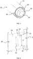
- the figure 1 illustrates a non-limiting embodiment of a plate 1 according to the invention.
- Platen 1 is shown only schematically in this appended figure. It is preferably a plate of an electrical switch (not shown).
- the plate 1 can be made of any suitable known material. Preferably, the plate 1 is made by plastic molding.
- the plate 1 can support active members of the electrical switch, including electrically conductive blades.
- the plate 1 is formed of a plate 1a but can of course be the subject of any variant adapted to the constraints of the electrical switch.
- the plate 1 comprises a shaft 2 extending orthogonally to the plate 1a along an axis X which makes it possible to fix the plate 1 on a steering column 20 (with reference to FIG. figure 5 ).
- the barrel 2 is axially slit orthogonal to the plate 1a.
- the internal diameter of the slit drum 2 at rest is adapted to be engaged around the steering column 20 of the vehicle (not shown) and then clamped on said column 20 with the aid of a clamp 3 and a screw and nut system 4.
- any other clamping means could be used.
- the plate 1 comprises, inside the barrel 2, a first annular element 5 of axis X and a second annular element 6 of axis X.
- the second annular element 6 of smaller diameter than the first annular element 5 defines an opening 7 arranged to receive a portion (not shown) of the steering column 20.
- the first annular element 5 extends from the plate 1a and comprises two support portions 8 projecting inside the barrel 2 parallel to the axis X.
- the plate 1 comprises in this example two diametrically opposite anti-rotation locking elements disposed inside the barrel 2.
- Each of the two anti-rotation locking elements 10 is in the form of a portion of material from the plate 1 which extends projecting parallel to the axis X of the barrel 2 between one of the support portions 8 and the barrel 2 from the annular element 5.
- the anti-rotation locking elements 10 are each arranged to cooperate by fitting with a cutout 30 of the steering column 20 (with reference to FIGS. Figures 5 and 6 ) as explained below.
- a plurality of anti-rotation locking elements 10 is provided on the plate 1 in order to lock it in rotation with respect to column 20.
- the cross section of the anti-rotation locking elements 10 is substantially in the form of an arc of a curvature whose value is of the order of that of the cutout 30 of the steering column 20 in order to allow a solid embedding.
- the anti-rotation locking elements 10 are made during the molding of the plate 1 in a manner known to those skilled in the art.
- the anti-rotation locking elements 10 may be attached to the plate 1.
- each anti-rotation locking element 10 comprises a portion made of a deformable plastic material, for example of PA6GF30 type known to those skilled in the art, so as to be deformed by matting when it is embedded in the corresponding cutout 30 of the steering column 20.
- a deformable plastic material for example of PA6GF30 type known to those skilled in the art
- said portion comprises a rib 12 configured to deform by matting during the force-embedding of the anti-rotation locking element 10 in the corresponding cutout 30 of the steering column 20.
- the width L1 of the anti-rotation locking element 10 at rest (ie before embedding) with the rib 12 is thus greater than or equal to the width L2 of the corresponding cutout 30 of the steering column 20.
- the width L2 of the blank 30 may be of the order of 12 mm and the width L1 of the anti-rotation locking element 10 at rest may be 12.225 mm, the rib 12 having a thickness of, for example, 0.225 mm.
- an anti-locking element rotation may comprise more than one portion made of a deformable material to allow it to be embedded in the corresponding cutout.
- these ribs 12 may be of a different thickness, for example smaller than 12.225 mm so as to avoid having to exert too much embedding force.
- the steering column 20 comprises two cutouts 30 each arranged to receive by embedding an anti-rotation locking element 10 of the plate 1.
- each of the cutouts 30 is U-shaped, the ends 32 of which are bevelled in order to facilitate the insertion and to allow the corresponding anti-rotation blocking element 10 of the plate 1 to be matted.
- the anti-rotation blocking elements 10 are first positioned opposite the corresponding cutouts 30 of the steering column 20.
- each of the anti-rotation locking elements 10 of the plate 1 is inserted into the corresponding cutout 30 of the steering column 20, the beveled ends 32 of the cuts facilitating the insertion and the embedding and the ribs. 12 deforming during embedding to securely hold the anti-rotation locking elements 10 embedded in the cutouts 30.
- the barrel 2 is tightened around the steering column 20 by means of the clamping means 3 and 4.
- anti-rotation locking elements 10 and cutouts 30 of different shapes taking into account the structure of the plate 1 and / or the structure of the column of direction 20.
- the present invention is not limited to the examples described above and is capable of numerous variants accessible to those skilled in the art.
- shape and dimensions of the plate 1, the barrel 3, anti-rotation locking elements 10, the steering column 20 and the cutouts 30 as shown in the figures so as to illustrate an exemplary embodiment of FIG. the invention can not be interpreted as limiting.
Landscapes
- Engineering & Computer Science (AREA)
- Chemical & Material Sciences (AREA)
- Combustion & Propulsion (AREA)
- Transportation (AREA)
- Mechanical Engineering (AREA)
- Steering Controls (AREA)
Claims (9)
- Platte, die dazu bestimmt ist, auf eine Lenksäule (20) eines Fahrzeugs montiert zu sein, wobei die Platte (1) eine Tafel (1a) umfasst, von der sich orthogonal ein Schaft (2), der axial gespaltet ist, erstreckt, der auf die Lenksäule (20) montiert werden kann, wobei die Platte (1) eine Mehrzahl von Drehschutzblockierungselementen (10) umfasst, die jeweils eingerichtet sind, um durch Einlassen mit einem Ausschnitt (30) der Lenksäule (20) zusammenzuwirken, dadurch gekennzeichnet, dass die Platte (1) zwei Drehschutzblockierungselemente (10) umfasst, wobei die zwei Drehschutzblockierungselemente (10) in Bezug auf die Achse (X) des Schafts (2) einander diametral gegenüber liegen.
- Platte nach dem vorhergehenden Anspruch, dadurch gekennzeichnet, dass sich die Drehschutzblockierungselemente (10) in dem Inneren des Schafts (2) parallel zu seiner Achse (X) vorragend erstrecken.
- Platte nach einem der vorhergehenden Ansprüche, dadurch gekennzeichnet, dass die Drehschutzblockierungselemente (10) mindestens einen Abschnitt umfassen, der aus einem verformbaren Material hergestellt und eingerichtet ist, um bei dem Einlassen des Drehschutzblockierungselements (10) in dem entsprechenden Ausschnitt (30) der Lenksäule (20) verformt zu werden.
- Platte nach dem vorhergehenden Anspruch, dadurch gekennzeichnet, dass der Abschnitt eine Rippe (12) umfasst, die sich parallel zu der Achse (X) des Schafts (2) erstreckt.
- Platte nach einem der vorhergehenden Ansprüche, dadurch gekennzeichnet, dass die Drehschutzblockierungselemente (10) aus einem Stück mit der Platte (1) bestehen.
- Lenksäule, dadurch gekennzeichnet, dass sie eine Vielzahl von Ausschnitten (30) umfasst, die jeweils eingerichtet sind, um durch Einlassen ein Drehschutzblockierungselement (10) einer Platte (1) nach einem der vorhergehenden Ansprüche aufzunehmen.
- Lenksäule nach dem vorhergehenden Anspruch, dadurch gekennzeichnet, dass jeder der Ausschnitte (30) die Form eines U hat, dessen Enden (32) abgeschrägt sind, um das Einsetzen zu erleichtern und das Verstemmen des entsprechenden Drehschutzblockierungselements (10) der Platte (1) zu erlauben.
- Baugruppe, die aus einer Platte (1) nach einem der Ansprüche 1 bis 5 und einer Lenksäule nach einem der Ansprüche 6 und 7 gebildet ist, dadurch gekennzeichnet, dass die Drehschutzblockierungselemente (10) der Platte (1) in die entsprechenden Ausschnitte (30) der Lenksäule (20) eingelassen sind.
- Verfahren zur Montage einer Baugruppe nach Anspruch 8, Verfahren dadurch gekennzeichnet, dass es einen Schritt des Einsetzens unter Kraftanwendung durch Einlassen der Drehschutzblockierungselemente (10) der Platte (1) in die entsprechenden Ausschnitte (30) der Lenksäule (20) umfasst.
Applications Claiming Priority (2)
| Application Number | Priority Date | Filing Date | Title |
|---|---|---|---|
| FR1361477A FR3013301B1 (fr) | 2013-11-21 | 2013-11-21 | Platine de commutateur electrique et colonne de direction d'un vehicule |
| PCT/FR2014/052810 WO2015075344A1 (fr) | 2013-11-21 | 2014-11-05 | Platine de commutateur electrique et colonne de direction d'un vehicule |
Publications (2)
| Publication Number | Publication Date |
|---|---|
| EP3074294A1 EP3074294A1 (de) | 2016-10-05 |
| EP3074294B1 true EP3074294B1 (de) | 2018-10-24 |
Family
ID=50102017
Family Applications (1)
| Application Number | Title | Priority Date | Filing Date |
|---|---|---|---|
| EP14806010.6A Active EP3074294B1 (de) | 2013-11-21 | 2014-11-05 | Platte eines elektrischen schalters und lenksäule eines fahrzeugs |
Country Status (4)
| Country | Link |
|---|---|
| EP (1) | EP3074294B1 (de) |
| CN (1) | CN105745137B (de) |
| FR (1) | FR3013301B1 (de) |
| WO (1) | WO2015075344A1 (de) |
Families Citing this family (1)
| Publication number | Priority date | Publication date | Assignee | Title |
|---|---|---|---|---|
| FR3144798A1 (fr) * | 2023-01-06 | 2024-07-12 | Psa Automobiles Sa | Dispositif d’aide à la solidarisation d’un boîtier de commande à une colonne de direction d’un véhicule |
Family Cites Families (6)
| Publication number | Priority date | Publication date | Assignee | Title |
|---|---|---|---|---|
| JPS58110336A (ja) * | 1981-12-24 | 1983-06-30 | Nissan Motor Co Ltd | スイツチボツクスの取付構造 |
| FR2702016B1 (fr) * | 1993-02-24 | 1995-07-07 | Ecia Equip Composants Ind Auto | Dispositif d'immobilisation temporaire de deux organes montes deplacables l'un dans l'autre, d'un ensemble de colonne de direction de vehicule automobile. |
| FR2833553B1 (fr) * | 2001-12-13 | 2004-03-05 | Valeo Electronique | Module pour haut de colonne de direction et ensemble muni de ce module |
| DE102004045876B4 (de) * | 2004-09-20 | 2006-07-06 | Delphi Technologies, Inc., Troy | Befestigungseinrichtung für ein Lenkstockmodul eines Kraftfahrzeuges |
| FR2950850B1 (fr) * | 2009-10-02 | 2012-01-13 | Renault Sa | Systeme de fixation d'un module pour haut de colonne de direction. |
| JP2012131420A (ja) * | 2010-12-22 | 2012-07-12 | Jtekt Corp | 車両用操舵装置 |
-
2013
- 2013-11-21 FR FR1361477A patent/FR3013301B1/fr active Active
-
2014
- 2014-11-05 CN CN201480063505.0A patent/CN105745137B/zh not_active Expired - Fee Related
- 2014-11-05 EP EP14806010.6A patent/EP3074294B1/de active Active
- 2014-11-05 WO PCT/FR2014/052810 patent/WO2015075344A1/fr not_active Ceased
Non-Patent Citations (1)
| Title |
|---|
| None * |
Also Published As
| Publication number | Publication date |
|---|---|
| WO2015075344A1 (fr) | 2015-05-28 |
| EP3074294A1 (de) | 2016-10-05 |
| CN105745137B (zh) | 2019-04-09 |
| FR3013301B1 (fr) | 2017-02-17 |
| CN105745137A (zh) | 2016-07-06 |
| FR3013301A1 (fr) | 2015-05-22 |
Similar Documents
| Publication | Publication Date | Title |
|---|---|---|
| FR2781259A1 (fr) | Cylindre hydraulique | |
| EP0276613A1 (de) | Kupplungsausrücklager, insbesondere für Kraftfahrzeug | |
| EP3206259B1 (de) | Elektroschaltgerät mit einer druckverbindungsklemme, die in einem gehäuse aus zwei teilen montiert ist, die nach der einschubrichtung eines elektrischen leiters in die verbindungsklemme zusammengebaut sind | |
| EP3074294B1 (de) | Platte eines elektrischen schalters und lenksäule eines fahrzeugs | |
| EP1963688B1 (de) | Anordnung zur zusammensetzung zweier teile durch schraubbefestigung über ein schrauben-muttern-system | |
| EP0149935A2 (de) | Vorrichtung zur abnehmbaren Befestigung einer Zierblende auf einem Fahrzeugrad und Montage mit Hilfe dieser Vorrichtung | |
| EP3658790B1 (de) | Mutterkäfigsystem mit einem mutterkäfig und einem träger, auf dem der käfig montiert werden soll | |
| EP4028292B1 (de) | Kurbelzapfen, kugelgelenk und entsprechendes scheibenwischerbetätigungsgestängesystem und verfahren zu dessen zusammenbau | |
| FR2956910A1 (fr) | Pedale pour vehicule comportant un patin rapporte sur l'ame de la pedale et patin correspondant | |
| EP1060555A1 (de) | Rotor mit zwischenliegenden dauermagneten für wechselstromgenerator für kraftfahrzeuge | |
| FR2928982A1 (fr) | Piece de frottement et ensemble support de pieces de frottement pour un assemblage de deux elements | |
| FR2952879A1 (fr) | Essuie-glace equipe d'une cale de montage. | |
| EP3375675B1 (de) | Abdeckung, verbindungsvorrichtung für die montage eines scheibenwischerblatts auf einem entsprechenden scheibenwischerarm, und entsprechendes scheibenwischsystem | |
| FR3117430A1 (fr) | Dispositif d’accrochage de boucle de ceinture de sécurité | |
| EP2665629B1 (de) | Scheibenwischervorrichtung für kraftfahrzeuge | |
| FR3013274A1 (fr) | Fixation d'une platine sur une colonne | |
| FR3056948B1 (fr) | Bloc de commande electrique pour garniture de portiere | |
| EP4051909B1 (de) | Motorträger und heizung-, lüftung- und/oder klimatisierungsgerät für automobiles fahrzeug | |
| EP3233586B1 (de) | Diebstahlsicherung für eine lenksäule | |
| WO2025141217A1 (fr) | Groupe moto-ventilateur notamment pour véhicule automobile | |
| WO2023208726A1 (fr) | Ensemble de connexion d'un système d'essuyage | |
| WO2025141227A1 (fr) | Groupe moto-ventilateur notamment pour véhicule automobile | |
| FR2715617A1 (fr) | Projecteur de véhicule, comportant des moyens perfectionnés de montage d'un correcteur de l'inclinaison du réflecteur. | |
| FR3034476A1 (fr) | Plaque de matage perfectionnee pour assemblage par vis | |
| EP1704335A1 (de) | Anordnung zur schraubbefestigung eines einrichtungselements an einem hohlkörper |
Legal Events
| Date | Code | Title | Description |
|---|---|---|---|
| PUAI | Public reference made under article 153(3) epc to a published international application that has entered the european phase |
Free format text: ORIGINAL CODE: 0009012 |
|
| 17P | Request for examination filed |
Effective date: 20160614 |
|
| AK | Designated contracting states |
Kind code of ref document: A1 Designated state(s): AL AT BE BG CH CY CZ DE DK EE ES FI FR GB GR HR HU IE IS IT LI LT LU LV MC MK MT NL NO PL PT RO RS SE SI SK SM TR |
|
| AX | Request for extension of the european patent |
Extension state: BA ME |
|
| DAX | Request for extension of the european patent (deleted) | ||
| RAP1 | Party data changed (applicant data changed or rights of an application transferred) |
Owner name: PSA AUTOMOBILES SA |
|
| GRAP | Despatch of communication of intention to grant a patent |
Free format text: ORIGINAL CODE: EPIDOSNIGR1 |
|
| INTG | Intention to grant announced |
Effective date: 20180531 |
|
| GRAS | Grant fee paid |
Free format text: ORIGINAL CODE: EPIDOSNIGR3 |
|
| GRAA | (expected) grant |
Free format text: ORIGINAL CODE: 0009210 |
|
| AK | Designated contracting states |
Kind code of ref document: B1 Designated state(s): AL AT BE BG CH CY CZ DE DK EE ES FI FR GB GR HR HU IE IS IT LI LT LU LV MC MK MT NL NO PL PT RO RS SE SI SK SM TR |
|
| REG | Reference to a national code |
Ref country code: CH Ref legal event code: EP |
|
| REG | Reference to a national code |
Ref country code: IE Ref legal event code: FG4D Free format text: LANGUAGE OF EP DOCUMENT: FRENCH |
|
| REG | Reference to a national code |
Ref country code: AT Ref legal event code: REF Ref document number: 1056328 Country of ref document: AT Kind code of ref document: T Effective date: 20181115 |
|
| REG | Reference to a national code |
Ref country code: DE Ref legal event code: R096 Ref document number: 602014034766 Country of ref document: DE |
|
| REG | Reference to a national code |
Ref country code: NL Ref legal event code: MP Effective date: 20181024 |
|
| REG | Reference to a national code |
Ref country code: LT Ref legal event code: MG4D |
|
| REG | Reference to a national code |
Ref country code: AT Ref legal event code: MK05 Ref document number: 1056328 Country of ref document: AT Kind code of ref document: T Effective date: 20181024 |
|
| PG25 | Lapsed in a contracting state [announced via postgrant information from national office to epo] |
Ref country code: NL Free format text: LAPSE BECAUSE OF FAILURE TO SUBMIT A TRANSLATION OF THE DESCRIPTION OR TO PAY THE FEE WITHIN THE PRESCRIBED TIME-LIMIT Effective date: 20181024 |
|
| PG25 | Lapsed in a contracting state [announced via postgrant information from national office to epo] |
Ref country code: ES Free format text: LAPSE BECAUSE OF FAILURE TO SUBMIT A TRANSLATION OF THE DESCRIPTION OR TO PAY THE FEE WITHIN THE PRESCRIBED TIME-LIMIT Effective date: 20181024 Ref country code: LV Free format text: LAPSE BECAUSE OF FAILURE TO SUBMIT A TRANSLATION OF THE DESCRIPTION OR TO PAY THE FEE WITHIN THE PRESCRIBED TIME-LIMIT Effective date: 20181024 Ref country code: AT Free format text: LAPSE BECAUSE OF FAILURE TO SUBMIT A TRANSLATION OF THE DESCRIPTION OR TO PAY THE FEE WITHIN THE PRESCRIBED TIME-LIMIT Effective date: 20181024 Ref country code: FI Free format text: LAPSE BECAUSE OF FAILURE TO SUBMIT A TRANSLATION OF THE DESCRIPTION OR TO PAY THE FEE WITHIN THE PRESCRIBED TIME-LIMIT Effective date: 20181024 Ref country code: IS Free format text: LAPSE BECAUSE OF FAILURE TO SUBMIT A TRANSLATION OF THE DESCRIPTION OR TO PAY THE FEE WITHIN THE PRESCRIBED TIME-LIMIT Effective date: 20190224 Ref country code: NO Free format text: LAPSE BECAUSE OF FAILURE TO SUBMIT A TRANSLATION OF THE DESCRIPTION OR TO PAY THE FEE WITHIN THE PRESCRIBED TIME-LIMIT Effective date: 20190124 Ref country code: HR Free format text: LAPSE BECAUSE OF FAILURE TO SUBMIT A TRANSLATION OF THE DESCRIPTION OR TO PAY THE FEE WITHIN THE PRESCRIBED TIME-LIMIT Effective date: 20181024 Ref country code: PL Free format text: LAPSE BECAUSE OF FAILURE TO SUBMIT A TRANSLATION OF THE DESCRIPTION OR TO PAY THE FEE WITHIN THE PRESCRIBED TIME-LIMIT Effective date: 20181024 Ref country code: BG Free format text: LAPSE BECAUSE OF FAILURE TO SUBMIT A TRANSLATION OF THE DESCRIPTION OR TO PAY THE FEE WITHIN THE PRESCRIBED TIME-LIMIT Effective date: 20190124 Ref country code: LT Free format text: LAPSE BECAUSE OF FAILURE TO SUBMIT A TRANSLATION OF THE DESCRIPTION OR TO PAY THE FEE WITHIN THE PRESCRIBED TIME-LIMIT Effective date: 20181024 |
|
| PG25 | Lapsed in a contracting state [announced via postgrant information from national office to epo] |
Ref country code: RS Free format text: LAPSE BECAUSE OF FAILURE TO SUBMIT A TRANSLATION OF THE DESCRIPTION OR TO PAY THE FEE WITHIN THE PRESCRIBED TIME-LIMIT Effective date: 20181024 Ref country code: SE Free format text: LAPSE BECAUSE OF FAILURE TO SUBMIT A TRANSLATION OF THE DESCRIPTION OR TO PAY THE FEE WITHIN THE PRESCRIBED TIME-LIMIT Effective date: 20181024 Ref country code: GR Free format text: LAPSE BECAUSE OF FAILURE TO SUBMIT A TRANSLATION OF THE DESCRIPTION OR TO PAY THE FEE WITHIN THE PRESCRIBED TIME-LIMIT Effective date: 20190125 Ref country code: PT Free format text: LAPSE BECAUSE OF FAILURE TO SUBMIT A TRANSLATION OF THE DESCRIPTION OR TO PAY THE FEE WITHIN THE PRESCRIBED TIME-LIMIT Effective date: 20190224 Ref country code: AL Free format text: LAPSE BECAUSE OF FAILURE TO SUBMIT A TRANSLATION OF THE DESCRIPTION OR TO PAY THE FEE WITHIN THE PRESCRIBED TIME-LIMIT Effective date: 20181024 |
|
| REG | Reference to a national code |
Ref country code: DE Ref legal event code: R084 Ref document number: 602014034766 Country of ref document: DE |
|
| REG | Reference to a national code |
Ref country code: CH Ref legal event code: PL |
|
| REG | Reference to a national code |
Ref country code: GB Ref legal event code: 746 Effective date: 20190618 |
|
| REG | Reference to a national code |
Ref country code: DE Ref legal event code: R097 Ref document number: 602014034766 Country of ref document: DE |
|
| PG25 | Lapsed in a contracting state [announced via postgrant information from national office to epo] |
Ref country code: LU Free format text: LAPSE BECAUSE OF NON-PAYMENT OF DUE FEES Effective date: 20181105 Ref country code: CZ Free format text: LAPSE BECAUSE OF FAILURE TO SUBMIT A TRANSLATION OF THE DESCRIPTION OR TO PAY THE FEE WITHIN THE PRESCRIBED TIME-LIMIT Effective date: 20181024 Ref country code: IT Free format text: LAPSE BECAUSE OF FAILURE TO SUBMIT A TRANSLATION OF THE DESCRIPTION OR TO PAY THE FEE WITHIN THE PRESCRIBED TIME-LIMIT Effective date: 20181024 Ref country code: DK Free format text: LAPSE BECAUSE OF FAILURE TO SUBMIT A TRANSLATION OF THE DESCRIPTION OR TO PAY THE FEE WITHIN THE PRESCRIBED TIME-LIMIT Effective date: 20181024 |
|
| REG | Reference to a national code |
Ref country code: BE Ref legal event code: MM Effective date: 20181130 |
|
| REG | Reference to a national code |
Ref country code: IE Ref legal event code: MM4A |
|
| PG25 | Lapsed in a contracting state [announced via postgrant information from national office to epo] |
Ref country code: RO Free format text: LAPSE BECAUSE OF FAILURE TO SUBMIT A TRANSLATION OF THE DESCRIPTION OR TO PAY THE FEE WITHIN THE PRESCRIBED TIME-LIMIT Effective date: 20181024 Ref country code: SK Free format text: LAPSE BECAUSE OF FAILURE TO SUBMIT A TRANSLATION OF THE DESCRIPTION OR TO PAY THE FEE WITHIN THE PRESCRIBED TIME-LIMIT Effective date: 20181024 Ref country code: SM Free format text: LAPSE BECAUSE OF FAILURE TO SUBMIT A TRANSLATION OF THE DESCRIPTION OR TO PAY THE FEE WITHIN THE PRESCRIBED TIME-LIMIT Effective date: 20181024 Ref country code: CH Free format text: LAPSE BECAUSE OF NON-PAYMENT OF DUE FEES Effective date: 20181130 Ref country code: EE Free format text: LAPSE BECAUSE OF FAILURE TO SUBMIT A TRANSLATION OF THE DESCRIPTION OR TO PAY THE FEE WITHIN THE PRESCRIBED TIME-LIMIT Effective date: 20181024 Ref country code: LI Free format text: LAPSE BECAUSE OF NON-PAYMENT OF DUE FEES Effective date: 20181130 Ref country code: MC Free format text: LAPSE BECAUSE OF FAILURE TO SUBMIT A TRANSLATION OF THE DESCRIPTION OR TO PAY THE FEE WITHIN THE PRESCRIBED TIME-LIMIT Effective date: 20181024 |
|
| PLBE | No opposition filed within time limit |
Free format text: ORIGINAL CODE: 0009261 |
|
| STAA | Information on the status of an ep patent application or granted ep patent |
Free format text: STATUS: NO OPPOSITION FILED WITHIN TIME LIMIT |
|
| 26N | No opposition filed |
Effective date: 20190725 |
|
| PG25 | Lapsed in a contracting state [announced via postgrant information from national office to epo] |
Ref country code: IE Free format text: LAPSE BECAUSE OF NON-PAYMENT OF DUE FEES Effective date: 20181105 Ref country code: SI Free format text: LAPSE BECAUSE OF FAILURE TO SUBMIT A TRANSLATION OF THE DESCRIPTION OR TO PAY THE FEE WITHIN THE PRESCRIBED TIME-LIMIT Effective date: 20181024 |
|
| PG25 | Lapsed in a contracting state [announced via postgrant information from national office to epo] |
Ref country code: BE Free format text: LAPSE BECAUSE OF NON-PAYMENT OF DUE FEES Effective date: 20181130 |
|
| PG25 | Lapsed in a contracting state [announced via postgrant information from national office to epo] |
Ref country code: MT Free format text: LAPSE BECAUSE OF FAILURE TO SUBMIT A TRANSLATION OF THE DESCRIPTION OR TO PAY THE FEE WITHIN THE PRESCRIBED TIME-LIMIT Effective date: 20181024 |
|
| PG25 | Lapsed in a contracting state [announced via postgrant information from national office to epo] |
Ref country code: TR Free format text: LAPSE BECAUSE OF FAILURE TO SUBMIT A TRANSLATION OF THE DESCRIPTION OR TO PAY THE FEE WITHIN THE PRESCRIBED TIME-LIMIT Effective date: 20181024 |
|
| PG25 | Lapsed in a contracting state [announced via postgrant information from national office to epo] |
Ref country code: MK Free format text: LAPSE BECAUSE OF NON-PAYMENT OF DUE FEES Effective date: 20181024 Ref country code: HU Free format text: LAPSE BECAUSE OF FAILURE TO SUBMIT A TRANSLATION OF THE DESCRIPTION OR TO PAY THE FEE WITHIN THE PRESCRIBED TIME-LIMIT; INVALID AB INITIO Effective date: 20141105 Ref country code: CY Free format text: LAPSE BECAUSE OF FAILURE TO SUBMIT A TRANSLATION OF THE DESCRIPTION OR TO PAY THE FEE WITHIN THE PRESCRIBED TIME-LIMIT Effective date: 20181024 |
|
| REG | Reference to a national code |
Ref country code: DE Ref legal event code: R081 Ref document number: 602014034766 Country of ref document: DE Owner name: STELLANTIS AUTO SAS, FR Free format text: FORMER OWNER: PSA AUTOMOBILES SA, POISSY, FR |
|
| PGFP | Annual fee paid to national office [announced via postgrant information from national office to epo] |
Ref country code: DE Payment date: 20251022 Year of fee payment: 12 |
|
| PGFP | Annual fee paid to national office [announced via postgrant information from national office to epo] |
Ref country code: GB Payment date: 20251022 Year of fee payment: 12 |
|
| PGFP | Annual fee paid to national office [announced via postgrant information from national office to epo] |
Ref country code: FR Payment date: 20251022 Year of fee payment: 12 |