EP3074687B1 - Apparatus and method for applying protective sheeting of polymer material to a pipeline - Google Patents
Apparatus and method for applying protective sheeting of polymer material to a pipeline Download PDFInfo
- Publication number
- EP3074687B1 EP3074687B1 EP14828295.7A EP14828295A EP3074687B1 EP 3074687 B1 EP3074687 B1 EP 3074687B1 EP 14828295 A EP14828295 A EP 14828295A EP 3074687 B1 EP3074687 B1 EP 3074687B1
- Authority
- EP
- European Patent Office
- Prior art keywords
- pipeline
- guide system
- cutback
- around
- hose
- Prior art date
- Legal status (The legal status is an assumption and is not a legal conclusion. Google has not performed a legal analysis and makes no representation as to the accuracy of the status listed.)
- Active
Links
Images


Classifications
-
- B—PERFORMING OPERATIONS; TRANSPORTING
- B29—WORKING OF PLASTICS; WORKING OF SUBSTANCES IN A PLASTIC STATE IN GENERAL
- B29C—SHAPING OR JOINING OF PLASTICS; SHAPING OF MATERIAL IN A PLASTIC STATE, NOT OTHERWISE PROVIDED FOR; AFTER-TREATMENT OF THE SHAPED PRODUCTS, e.g. REPAIRING
- B29C63/00—Lining or sheathing, i.e. applying preformed layers or sheathings of plastics; Apparatus therefor
- B29C63/02—Lining or sheathing, i.e. applying preformed layers or sheathings of plastics; Apparatus therefor using sheet or web-like material
- B29C63/04—Lining or sheathing, i.e. applying preformed layers or sheathings of plastics; Apparatus therefor using sheet or web-like material by folding, winding, bending or the like
- B29C63/06—Lining or sheathing, i.e. applying preformed layers or sheathings of plastics; Apparatus therefor using sheet or web-like material by folding, winding, bending or the like around tubular articles
-
- B—PERFORMING OPERATIONS; TRANSPORTING
- B29—WORKING OF PLASTICS; WORKING OF SUBSTANCES IN A PLASTIC STATE IN GENERAL
- B29C—SHAPING OR JOINING OF PLASTICS; SHAPING OF MATERIAL IN A PLASTIC STATE, NOT OTHERWISE PROVIDED FOR; AFTER-TREATMENT OF THE SHAPED PRODUCTS, e.g. REPAIRING
- B29C48/00—Extrusion moulding, i.e. expressing the moulding material through a die or nozzle which imparts the desired form; Apparatus therefor
- B29C48/15—Extrusion moulding, i.e. expressing the moulding material through a die or nozzle which imparts the desired form; Apparatus therefor incorporating preformed parts or layers, e.g. extrusion moulding around inserts
- B29C48/151—Coating hollow articles
-
- B—PERFORMING OPERATIONS; TRANSPORTING
- B29—WORKING OF PLASTICS; WORKING OF SUBSTANCES IN A PLASTIC STATE IN GENERAL
- B29C—SHAPING OR JOINING OF PLASTICS; SHAPING OF MATERIAL IN A PLASTIC STATE, NOT OTHERWISE PROVIDED FOR; AFTER-TREATMENT OF THE SHAPED PRODUCTS, e.g. REPAIRING
- B29C48/00—Extrusion moulding, i.e. expressing the moulding material through a die or nozzle which imparts the desired form; Apparatus therefor
- B29C48/25—Component parts, details or accessories; Auxiliary operations
- B29C48/266—Means for allowing relative movements between the apparatus parts, e.g. for twisting the extruded article or for moving the die along a surface to be coated
-
- B—PERFORMING OPERATIONS; TRANSPORTING
- B29—WORKING OF PLASTICS; WORKING OF SUBSTANCES IN A PLASTIC STATE IN GENERAL
- B29C—SHAPING OR JOINING OF PLASTICS; SHAPING OF MATERIAL IN A PLASTIC STATE, NOT OTHERWISE PROVIDED FOR; AFTER-TREATMENT OF THE SHAPED PRODUCTS, e.g. REPAIRING
- B29C63/00—Lining or sheathing, i.e. applying preformed layers or sheathings of plastics; Apparatus therefor
- B29C63/02—Lining or sheathing, i.e. applying preformed layers or sheathings of plastics; Apparatus therefor using sheet or web-like material
- B29C63/024—Lining or sheathing, i.e. applying preformed layers or sheathings of plastics; Apparatus therefor using sheet or web-like material the sheet or web-like material being supported by a moving carriage
-
- B—PERFORMING OPERATIONS; TRANSPORTING
- B29—WORKING OF PLASTICS; WORKING OF SUBSTANCES IN A PLASTIC STATE IN GENERAL
- B29C—SHAPING OR JOINING OF PLASTICS; SHAPING OF MATERIAL IN A PLASTIC STATE, NOT OTHERWISE PROVIDED FOR; AFTER-TREATMENT OF THE SHAPED PRODUCTS, e.g. REPAIRING
- B29C65/00—Joining or sealing of preformed parts, e.g. welding of plastics materials; Apparatus therefor
- B29C65/02—Joining or sealing of preformed parts, e.g. welding of plastics materials; Apparatus therefor by heating, with or without pressure
- B29C65/022—Particular heating or welding methods not otherwise provided for
- B29C65/028—Particular heating or welding methods not otherwise provided for making use of inherent heat, i.e. the heat for the joining comes from the moulding process of one of the parts to be joined
-
- B—PERFORMING OPERATIONS; TRANSPORTING
- B29—WORKING OF PLASTICS; WORKING OF SUBSTANCES IN A PLASTIC STATE IN GENERAL
- B29C—SHAPING OR JOINING OF PLASTICS; SHAPING OF MATERIAL IN A PLASTIC STATE, NOT OTHERWISE PROVIDED FOR; AFTER-TREATMENT OF THE SHAPED PRODUCTS, e.g. REPAIRING
- B29C66/00—General aspects of processes or apparatus for joining preformed parts
- B29C66/01—General aspects dealing with the joint area or with the area to be joined
- B29C66/02—Preparation of the material, in the area to be joined, prior to joining or welding
- B29C66/024—Thermal pre-treatments
- B29C66/0242—Heating, or preheating, e.g. drying
-
- B—PERFORMING OPERATIONS; TRANSPORTING
- B29—WORKING OF PLASTICS; WORKING OF SUBSTANCES IN A PLASTIC STATE IN GENERAL
- B29C—SHAPING OR JOINING OF PLASTICS; SHAPING OF MATERIAL IN A PLASTIC STATE, NOT OTHERWISE PROVIDED FOR; AFTER-TREATMENT OF THE SHAPED PRODUCTS, e.g. REPAIRING
- B29C66/00—General aspects of processes or apparatus for joining preformed parts
- B29C66/01—General aspects dealing with the joint area or with the area to be joined
- B29C66/05—Particular design of joint configurations
- B29C66/10—Particular design of joint configurations particular design of the joint cross-sections
- B29C66/11—Joint cross-sections comprising a single joint-segment, i.e. one of the parts to be joined comprising a single joint-segment in the joint cross-section
- B29C66/112—Single lapped joints
- B29C66/1122—Single lap to lap joints, i.e. overlap joints
-
- B—PERFORMING OPERATIONS; TRANSPORTING
- B29—WORKING OF PLASTICS; WORKING OF SUBSTANCES IN A PLASTIC STATE IN GENERAL
- B29C—SHAPING OR JOINING OF PLASTICS; SHAPING OF MATERIAL IN A PLASTIC STATE, NOT OTHERWISE PROVIDED FOR; AFTER-TREATMENT OF THE SHAPED PRODUCTS, e.g. REPAIRING
- B29C66/00—General aspects of processes or apparatus for joining preformed parts
- B29C66/01—General aspects dealing with the joint area or with the area to be joined
- B29C66/05—Particular design of joint configurations
- B29C66/10—Particular design of joint configurations particular design of the joint cross-sections
- B29C66/12—Joint cross-sections combining only two joint-segments; Tongue and groove joints; Tenon and mortise joints; Stepped joint cross-sections
- B29C66/128—Stepped joint cross-sections
- B29C66/1282—Stepped joint cross-sections comprising at least one overlap joint-segment
- B29C66/12821—Stepped joint cross-sections comprising at least one overlap joint-segment comprising at least two overlap joint-segments
-
- B—PERFORMING OPERATIONS; TRANSPORTING
- B29—WORKING OF PLASTICS; WORKING OF SUBSTANCES IN A PLASTIC STATE IN GENERAL
- B29C—SHAPING OR JOINING OF PLASTICS; SHAPING OF MATERIAL IN A PLASTIC STATE, NOT OTHERWISE PROVIDED FOR; AFTER-TREATMENT OF THE SHAPED PRODUCTS, e.g. REPAIRING
- B29C66/00—General aspects of processes or apparatus for joining preformed parts
- B29C66/01—General aspects dealing with the joint area or with the area to be joined
- B29C66/05—Particular design of joint configurations
- B29C66/10—Particular design of joint configurations particular design of the joint cross-sections
- B29C66/12—Joint cross-sections combining only two joint-segments; Tongue and groove joints; Tenon and mortise joints; Stepped joint cross-sections
- B29C66/128—Stepped joint cross-sections
- B29C66/1286—Stepped joint cross-sections comprising at least one bevelled joint-segment
-
- B—PERFORMING OPERATIONS; TRANSPORTING
- B29—WORKING OF PLASTICS; WORKING OF SUBSTANCES IN A PLASTIC STATE IN GENERAL
- B29C—SHAPING OR JOINING OF PLASTICS; SHAPING OF MATERIAL IN A PLASTIC STATE, NOT OTHERWISE PROVIDED FOR; AFTER-TREATMENT OF THE SHAPED PRODUCTS, e.g. REPAIRING
- B29C66/00—General aspects of processes or apparatus for joining preformed parts
- B29C66/50—General aspects of joining tubular articles; General aspects of joining long products, i.e. bars or profiled elements; General aspects of joining single elements to tubular articles, hollow articles or bars; General aspects of joining several hollow-preforms to form hollow or tubular articles
- B29C66/51—Joining tubular articles, profiled elements or bars; Joining single elements to tubular articles, hollow articles or bars; Joining several hollow-preforms to form hollow or tubular articles
- B29C66/53—Joining single elements to tubular articles, hollow articles or bars
- B29C66/532—Joining single elements to the wall of tubular articles, hollow articles or bars
- B29C66/5326—Joining single elements to the wall of tubular articles, hollow articles or bars said single elements being substantially flat
-
- B—PERFORMING OPERATIONS; TRANSPORTING
- B29—WORKING OF PLASTICS; WORKING OF SUBSTANCES IN A PLASTIC STATE IN GENERAL
- B29C—SHAPING OR JOINING OF PLASTICS; SHAPING OF MATERIAL IN A PLASTIC STATE, NOT OTHERWISE PROVIDED FOR; AFTER-TREATMENT OF THE SHAPED PRODUCTS, e.g. REPAIRING
- B29C66/00—General aspects of processes or apparatus for joining preformed parts
- B29C66/50—General aspects of joining tubular articles; General aspects of joining long products, i.e. bars or profiled elements; General aspects of joining single elements to tubular articles, hollow articles or bars; General aspects of joining several hollow-preforms to form hollow or tubular articles
- B29C66/65—General aspects of joining tubular articles; General aspects of joining long products, i.e. bars or profiled elements; General aspects of joining single elements to tubular articles, hollow articles or bars; General aspects of joining several hollow-preforms to form hollow or tubular articles with a relative motion between the article and the welding tool
- B29C66/652—General aspects of joining tubular articles; General aspects of joining long products, i.e. bars or profiled elements; General aspects of joining single elements to tubular articles, hollow articles or bars; General aspects of joining several hollow-preforms to form hollow or tubular articles with a relative motion between the article and the welding tool moving the welding tool around the fixed article
-
- B—PERFORMING OPERATIONS; TRANSPORTING
- B29—WORKING OF PLASTICS; WORKING OF SUBSTANCES IN A PLASTIC STATE IN GENERAL
- B29C—SHAPING OR JOINING OF PLASTICS; SHAPING OF MATERIAL IN A PLASTIC STATE, NOT OTHERWISE PROVIDED FOR; AFTER-TREATMENT OF THE SHAPED PRODUCTS, e.g. REPAIRING
- B29C66/00—General aspects of processes or apparatus for joining preformed parts
- B29C66/70—General aspects of processes or apparatus for joining preformed parts characterised by the composition, physical properties or the structure of the material of the parts to be joined; Joining with non-plastics material
- B29C66/72—General aspects of processes or apparatus for joining preformed parts characterised by the composition, physical properties or the structure of the material of the parts to be joined; Joining with non-plastics material characterised by the structure of the material of the parts to be joined
- B29C66/723—General aspects of processes or apparatus for joining preformed parts characterised by the composition, physical properties or the structure of the material of the parts to be joined; Joining with non-plastics material characterised by the structure of the material of the parts to be joined being multi-layered
- B29C66/7232—General aspects of processes or apparatus for joining preformed parts characterised by the composition, physical properties or the structure of the material of the parts to be joined; Joining with non-plastics material characterised by the structure of the material of the parts to be joined being multi-layered comprising a non-plastics layer
- B29C66/72321—General aspects of processes or apparatus for joining preformed parts characterised by the composition, physical properties or the structure of the material of the parts to be joined; Joining with non-plastics material characterised by the structure of the material of the parts to be joined being multi-layered comprising a non-plastics layer consisting of metals or their alloys
-
- B—PERFORMING OPERATIONS; TRANSPORTING
- B29—WORKING OF PLASTICS; WORKING OF SUBSTANCES IN A PLASTIC STATE IN GENERAL
- B29C—SHAPING OR JOINING OF PLASTICS; SHAPING OF MATERIAL IN A PLASTIC STATE, NOT OTHERWISE PROVIDED FOR; AFTER-TREATMENT OF THE SHAPED PRODUCTS, e.g. REPAIRING
- B29C66/00—General aspects of processes or apparatus for joining preformed parts
- B29C66/70—General aspects of processes or apparatus for joining preformed parts characterised by the composition, physical properties or the structure of the material of the parts to be joined; Joining with non-plastics material
- B29C66/74—Joining plastics material to non-plastics material
- B29C66/742—Joining plastics material to non-plastics material to metals or their alloys
-
- B—PERFORMING OPERATIONS; TRANSPORTING
- B29—WORKING OF PLASTICS; WORKING OF SUBSTANCES IN A PLASTIC STATE IN GENERAL
- B29C—SHAPING OR JOINING OF PLASTICS; SHAPING OF MATERIAL IN A PLASTIC STATE, NOT OTHERWISE PROVIDED FOR; AFTER-TREATMENT OF THE SHAPED PRODUCTS, e.g. REPAIRING
- B29C66/00—General aspects of processes or apparatus for joining preformed parts
- B29C66/80—General aspects of machine operations or constructions and parts thereof
- B29C66/83—General aspects of machine operations or constructions and parts thereof characterised by the movement of the joining or pressing tools
- B29C66/836—Moving relative to and tangentially to the parts to be joined, e.g. transversely to the displacement of the parts to be joined, e.g. using a X-Y table
- B29C66/8362—Rollers, cylinders or drums moving relative to and tangentially to the parts to be joined
-
- F—MECHANICAL ENGINEERING; LIGHTING; HEATING; WEAPONS; BLASTING
- F16—ENGINEERING ELEMENTS AND UNITS; GENERAL MEASURES FOR PRODUCING AND MAINTAINING EFFECTIVE FUNCTIONING OF MACHINES OR INSTALLATIONS; THERMAL INSULATION IN GENERAL
- F16L—PIPES; JOINTS OR FITTINGS FOR PIPES; SUPPORTS FOR PIPES, CABLES OR PROTECTIVE TUBING; MEANS FOR THERMAL INSULATION IN GENERAL
- F16L1/00—Laying or reclaiming pipes; Repairing or joining pipes on or under water
- F16L1/12—Laying or reclaiming pipes on or under water
- F16L1/20—Accessories therefor, e.g. floats or weights
- F16L1/202—Accessories therefor, e.g. floats or weights fixed on or to vessels
- F16L1/207—Pipe handling apparatus
-
- F—MECHANICAL ENGINEERING; LIGHTING; HEATING; WEAPONS; BLASTING
- F16—ENGINEERING ELEMENTS AND UNITS; GENERAL MEASURES FOR PRODUCING AND MAINTAINING EFFECTIVE FUNCTIONING OF MACHINES OR INSTALLATIONS; THERMAL INSULATION IN GENERAL
- F16L—PIPES; JOINTS OR FITTINGS FOR PIPES; SUPPORTS FOR PIPES, CABLES OR PROTECTIVE TUBING; MEANS FOR THERMAL INSULATION IN GENERAL
- F16L13/00—Non-disconnectable pipe joints, e.g. soldered, adhesive, or caulked joints
- F16L13/02—Welded joints
- F16L13/0254—Welded joints the pipes having an internal or external coating
- F16L13/0272—Welded joints the pipes having an internal or external coating having an external coating
-
- F—MECHANICAL ENGINEERING; LIGHTING; HEATING; WEAPONS; BLASTING
- F16—ENGINEERING ELEMENTS AND UNITS; GENERAL MEASURES FOR PRODUCING AND MAINTAINING EFFECTIVE FUNCTIONING OF MACHINES OR INSTALLATIONS; THERMAL INSULATION IN GENERAL
- F16L—PIPES; JOINTS OR FITTINGS FOR PIPES; SUPPORTS FOR PIPES, CABLES OR PROTECTIVE TUBING; MEANS FOR THERMAL INSULATION IN GENERAL
- F16L58/00—Protection of pipes or pipe fittings against corrosion or incrustation
- F16L58/18—Protection of pipes or pipe fittings against corrosion or incrustation specially adapted for pipe fittings
- F16L58/181—Protection of pipes or pipe fittings against corrosion or incrustation specially adapted for pipe fittings for non-disconnectable pipe joints
-
- B—PERFORMING OPERATIONS; TRANSPORTING
- B29—WORKING OF PLASTICS; WORKING OF SUBSTANCES IN A PLASTIC STATE IN GENERAL
- B29C—SHAPING OR JOINING OF PLASTICS; SHAPING OF MATERIAL IN A PLASTIC STATE, NOT OTHERWISE PROVIDED FOR; AFTER-TREATMENT OF THE SHAPED PRODUCTS, e.g. REPAIRING
- B29C48/00—Extrusion moulding, i.e. expressing the moulding material through a die or nozzle which imparts the desired form; Apparatus therefor
- B29C48/03—Extrusion moulding, i.e. expressing the moulding material through a die or nozzle which imparts the desired form; Apparatus therefor characterised by the shape of the extruded material at extrusion
- B29C48/09—Articles with cross-sections having partially or fully enclosed cavities, e.g. pipes or channels
-
- B—PERFORMING OPERATIONS; TRANSPORTING
- B29—WORKING OF PLASTICS; WORKING OF SUBSTANCES IN A PLASTIC STATE IN GENERAL
- B29C—SHAPING OR JOINING OF PLASTICS; SHAPING OF MATERIAL IN A PLASTIC STATE, NOT OTHERWISE PROVIDED FOR; AFTER-TREATMENT OF THE SHAPED PRODUCTS, e.g. REPAIRING
- B29C66/00—General aspects of processes or apparatus for joining preformed parts
- B29C66/70—General aspects of processes or apparatus for joining preformed parts characterised by the composition, physical properties or the structure of the material of the parts to be joined; Joining with non-plastics material
- B29C66/71—General aspects of processes or apparatus for joining preformed parts characterised by the composition, physical properties or the structure of the material of the parts to be joined; Joining with non-plastics material characterised by the composition of the plastics material of the parts to be joined
-
- B—PERFORMING OPERATIONS; TRANSPORTING
- B29—WORKING OF PLASTICS; WORKING OF SUBSTANCES IN A PLASTIC STATE IN GENERAL
- B29C—SHAPING OR JOINING OF PLASTICS; SHAPING OF MATERIAL IN A PLASTIC STATE, NOT OTHERWISE PROVIDED FOR; AFTER-TREATMENT OF THE SHAPED PRODUCTS, e.g. REPAIRING
- B29C66/00—General aspects of processes or apparatus for joining preformed parts
- B29C66/70—General aspects of processes or apparatus for joining preformed parts characterised by the composition, physical properties or the structure of the material of the parts to be joined; Joining with non-plastics material
- B29C66/73—General aspects of processes or apparatus for joining preformed parts characterised by the composition, physical properties or the structure of the material of the parts to be joined; Joining with non-plastics material characterised by the intensive physical properties of the material of the parts to be joined, by the optical properties of the material of the parts to be joined, by the extensive physical properties of the parts to be joined, by the state of the material of the parts to be joined or by the material of the parts to be joined being a thermoplastic or a thermoset
- B29C66/739—General aspects of processes or apparatus for joining preformed parts characterised by the composition, physical properties or the structure of the material of the parts to be joined; Joining with non-plastics material characterised by the intensive physical properties of the material of the parts to be joined, by the optical properties of the material of the parts to be joined, by the extensive physical properties of the parts to be joined, by the state of the material of the parts to be joined or by the material of the parts to be joined being a thermoplastic or a thermoset characterised by the material of the parts to be joined being a thermoplastic or a thermoset
- B29C66/7392—General aspects of processes or apparatus for joining preformed parts characterised by the composition, physical properties or the structure of the material of the parts to be joined; Joining with non-plastics material characterised by the intensive physical properties of the material of the parts to be joined, by the optical properties of the material of the parts to be joined, by the extensive physical properties of the parts to be joined, by the state of the material of the parts to be joined or by the material of the parts to be joined being a thermoplastic or a thermoset characterised by the material of the parts to be joined being a thermoplastic or a thermoset characterised by the material of at least one of the parts being a thermoplastic
-
- B—PERFORMING OPERATIONS; TRANSPORTING
- B29—WORKING OF PLASTICS; WORKING OF SUBSTANCES IN A PLASTIC STATE IN GENERAL
- B29K—INDEXING SCHEME ASSOCIATED WITH SUBCLASSES B29B, B29C OR B29D, RELATING TO MOULDING MATERIALS OR TO MATERIALS FOR MOULDS, REINFORCEMENTS, FILLERS OR PREFORMED PARTS, e.g. INSERTS
- B29K2023/00—Use of polyalkenes or derivatives thereof as moulding material
- B29K2023/04—Polymers of ethylene
- B29K2023/06—PE, i.e. polyethylene
-
- B—PERFORMING OPERATIONS; TRANSPORTING
- B29—WORKING OF PLASTICS; WORKING OF SUBSTANCES IN A PLASTIC STATE IN GENERAL
- B29K—INDEXING SCHEME ASSOCIATED WITH SUBCLASSES B29B, B29C OR B29D, RELATING TO MOULDING MATERIALS OR TO MATERIALS FOR MOULDS, REINFORCEMENTS, FILLERS OR PREFORMED PARTS, e.g. INSERTS
- B29K2023/00—Use of polyalkenes or derivatives thereof as moulding material
- B29K2023/10—Polymers of propylene
- B29K2023/12—PP, i.e. polypropylene
-
- B—PERFORMING OPERATIONS; TRANSPORTING
- B29—WORKING OF PLASTICS; WORKING OF SUBSTANCES IN A PLASTIC STATE IN GENERAL
- B29K—INDEXING SCHEME ASSOCIATED WITH SUBCLASSES B29B, B29C OR B29D, RELATING TO MOULDING MATERIALS OR TO MATERIALS FOR MOULDS, REINFORCEMENTS, FILLERS OR PREFORMED PARTS, e.g. INSERTS
- B29K2705/00—Use of metals, their alloys or their compounds, for preformed parts, e.g. for inserts
-
- B—PERFORMING OPERATIONS; TRANSPORTING
- B29—WORKING OF PLASTICS; WORKING OF SUBSTANCES IN A PLASTIC STATE IN GENERAL
- B29L—INDEXING SCHEME ASSOCIATED WITH SUBCLASS B29C, RELATING TO PARTICULAR ARTICLES
- B29L2023/00—Tubular articles
- B29L2023/22—Tubes or pipes, i.e. rigid
Definitions
- the present invention relates to an apparatus for applying protective sheeting of polymer material to a pipeline, in particular around a cutback on a substantially vertical pipeline.
- the apparatus according to the present invention is used on a pipeline construction line, in particular for constructing underwater pipelines for laying on the bed of a body of water, and to which the following description refers purely by way of example.
- Underwater pipelines are normally constructed by joining the facing free ends of adjacent pipes aligned along a longitudinal axis to define a cutback; and winding protective sheeting about the cutback.
- Pipelines in fact, are composed of pipes joined to one another to cover distances of hundreds of kilometres.
- the pipes are of normally 12-metre standard length and of relatively large diameter ranging from 0.2 to 1.5 metres.
- Each pipe comprises a metal cylinder; and a polymer coating for protecting the metal cylinder.
- the opposite ends of each pipe have no coating, so the metal cylinders can be welded to one another.
- the pipes may be joined at land-based installations, or on laying vessels which normally also provide for laying the pipeline as it is constructed.
- the joining operation comprises welding the metal cylinders together, normally with a number of weld passes; and coating the cutback.
- Welding forms an annular weld bead projecting between the adjacent metal cylinders.
- the cutback extends astride the annular weld bead, along an uncoated portion.
- the cutback is substantially defined by the free ends of the pipes, extends axially between two end portions of the coating, and must be covered with protective sheeting to prevent corrosion.
- One known field joint coating method is to apply protective sheeting to the cutback as it is extruded.
- various apparatuses have been made known in this particular field of technology.
- the Applicant in particular, has developed a number of techniques based on the principles expounded in Patents EP 2,100,068 and EP 2,535,168 and Patent Application EP 2,535,639 .
- Other significant documentation includes EP 1,985,909 , EP 1,998,903 , EP 2,181,832 , EP 2,477,796 and EP 2,477,758 .
- the above documents relate to apparatuses for applying protecting sheeting to a cutback using an extruder die mounted on a guide and movable along an annular path around the longitudinal axis of the pipeline to extrude and simultaneously apply the protective sheeting to the pipeline.
- an apparatus for applying protective sheeting of polymer material around a cutback on a pipeline comprising a frame located close to a pipeline extending along a longitudinal axis; a manipulator fitted to the frame and comprising a guide system movable between a rest position at a distance from the pipeline, and a work position in which the guide system is fitted around the pipeline; and an extrusion die movable selectively along the guide system and around the pipeline to supply and apply protective sheeting around the cutback on the pipeline.
- the protective sheeting can thus be applied using an extrusion die which rotates about the pipeline on a guide system fitted around the pipeline. Once the protective sheeting is applied, the guide system is withdrawn a good distance from the pipeline into a safe position, as the pipeline is moved forward to feed the next cutback to the apparatus, and/or to prevent interfering with any preliminary work carried out on the cutback by other apparatuses prior to applying the protective sheeting.
- the guide system comprises a number of spacers which, in the work position, are positioned contacting the pipeline to centre the guide system around the pipeline, and are designed to permit axial movement of the guide system with respect to the pipeline.
- the pipeline is fed forward in steps and, because of its size and mass, is difficult to stop in a precise position ensuring the cutbacks, at each step, are located in the exact same position with respect to the guide system.
- the guide system as opposed to gripping the pipeline, forms a coupling enabling it to move along the pipeline.
- the spacers are divided into two axially spaced groups, each comprising at least three spacers arranged around the longitudinal axis.
- the groups of spacers are spaced apart by a distance greater than the width of the cutback.
- each spacer comprises a roller designed to contact the pipeline and assist axial movement between the guide system and the pipeline.
- the manipulator is movable selectively with respect to the frame to axially adjust the position of the guide system with respect to the cutback on the pipeline.
- the guide system comprises at least one sensor to determine the axial position of the guide system with respect to the cutback.
- the characteristic conformation of the cutback enables the axial position of the guide system with respect to the cutback to be determined using a sensor.
- the sensor supplies signals comparable with reference values to adjust the axial position of the guide system.
- the manipulator comprises an articulated system for moving the guide system between the work position and the rest position; and a universal joint to connect the articulated system to the guide system and permit angular movement of the guide system with respect to the articulated system when the guide system is positioned contacting the pipeline, in the work position.
- the freedom of movement allowed by the universal joint thus allows the guide system to align perfectly with the pipeline at the final stage in connection to the pipeline.
- the manipulator serves to move the system between a work position and a rest position, to determine the axial position of the guide system, and to prevent the guide system, in the work position, from rotating about the pipeline.
- the apparatus comprises an extrusion device which is fitted to the guide system, and is connected by a hose to the extrusion die to permit relative movement between the extrusion die and the extrusion device.
- the extrusion device and extrusion die are thus relatively close to each other, with no need to move the extrusion device around the pipeline.
- the apparatus comprises a winder for winding and unwinding the hose according to the position of the extrusion die with respect to the guide system.
- the hose is controlled and guided to prevent it from forming tight bends and becoming crushed, thus cutting off all or part of the soft material supply to the extrusion die.
- the winder comprises a reel which rotates about a rotation axis to wind and unwind the hose according to the position of the extrusion die with respect to the guide system.
- Controlling the hose comprises seating it inside assigned seats, in which it does not interfere with other parts of the apparatus.
- the apparatus comprises a rotary hydraulic joint having a rotating portion that rotates about the rotation axis and is connected to the hose, and a fixed part connected rigidly to the outlet of the extrusion device.
- the reel and the rotating portion of the rotary hydraulic joint are powered to rotate both ways around the rotation axis.
- This provides for synchronizing movement with the movement of the extrusion die around the pipeline.
- the apparatus comprises a plastifying device; and a further hose for connecting the plastifying device to the extrusion device and allowing relative movement between the plastifying device and the extrusion device.
- the plastifying device is preferably mounted on the articulated system.
- the plastifying device is mounted on the manipulator.
- a further object of the present invention is to provide a highly efficient work station for applying protective sheeting to a cutback on a pipeline.
- a work station for applying protective sheeting to a cutback on a pipeline comprising an apparatus as claimed for applying protective sheeting around a cutback on a pipeline; and at least one further apparatus for performing operations preliminary to application of the protective sheeting; the further apparatus and the apparatus being fitted successively about the pipeline and about the cutback.
- a further object of the present invention is to provide a method of applying protective sheeting of polymer material about a cutback on a pipeline.
- a method of applying protective sheeting of polymer material around a cutback on a pipeline comprising the steps of selectively setting a guide system by means of a manipulator fitted to a frame to a work position, in which the guide system is fitted around a pipeline extending along a longitudinal axis, and a rest position, in which the guide system is relatively distant from the pipeline; and moving an extrusion die, guided by the guide system, around the pipeline to supply and apply protective sheeting around a cutback on the pipeline.
- the guide system does not interfere with the pipeline as it is moved forward, or with any other work carried out on the cutback.
- the method comprises centring the guide system around the pipeline by means of spacers; and axially adjusting the position of the guide system with respect to the cutback.
- Centring the guide system around the pipeline is an important, highly precise operation, to ensure constant clearance of the extrusion die as it travels around the pipeline. Equally important is the axial position of the guide system, to ensure a given position of the protective sheeting with respect to the cutback.
- the method comprises moving the guide system by means of an articulated system; and axially adjusting the position of the articulated system to axially adjust the position of the guide system with respect to the cutback on the pipeline.
- the method comprises determining the axial position of the guide system with respect to the cutback.
- a closed-loop system can be formed to position the guide system axially.
- the method comprises the step of supporting the guide system in the work position by means of an articulated system connected to the guide system by a universal joint, so as to centre and align the guide system on and with the pipeline.
- the guide system when being fitted around the pipeline, the guide system must be free to orient itself parallel to the pipeline.
- the method comprises transferring the soft polymer material from an extrusion device, mounted on the guide system, to the extrusion die by means of a hose, so as to allow relative movement between the extrusion die and the extrusion device.
- the hose allows the extrusion die to move freely with respect to the extrusion device.
- the method comprises winding and unwinding the hose according to the position of the extrusion die along the guide system.
- the hose allows freedom of movement, it is best to control its position to prevent it from bending and/or getting into unfavourable or interference positions.
- the method comprises transferring the soft polymer material from a plastifying device to the extrusion device by means of a further hose designed to connect the plastifying device to the extrusion device and to allow relative movement between the plastifying device and the extrusion device.
- the plastifying process involves feeding the polymer material, in the form of solid granules, to the plastifying device, and this operation is preferably performed relatively far from the pipeline.
- Number 1 in Figures 1 and 2 indicates as a whole a pipeline extending along a longitudinal axis A1.
- pipeline 1 comprises two pipes 2 aligned along longitudinal axis A1.
- Each pipe 2 comprises a metal cylinder 3; and a polymer coating 4, normally of polyethylene or polypropylene, contacting and for corrosion-proofing metal cylinder 3.
- Each pipe 2 has two opposite free ends 5 (only one of which is shown in Figure 1 ) with no coating 4, which has a bevel 6 at each free end 5.
- Two consecutive pipes 2 aligned along longitudinal axis A1 are positioned with their free ends 5 contacting, and are welded, possibly with a number of weld passes, to form an annular weld bead 7 between pipes 2.
- the two welded pipes 2 define a cutback 8, which extends along longitudinal axis A1, between the two consecutive bevels 6 of coatings 4, and comprises annular weld bead 7.
- Joining pipes 2 forms pipeline 1.
- 'pipeline 1' is also intended to mean the pipeline as it is being constructed, and even only comprising, for example, two joined pipes 2.
- joining pipes 2 also comprises forming a covering seamlessly connecting existing coatings 4. This comprises applying protective sheeting 9 around cutback 8 and two end portions 10 of coatings 4; and causing the protective sheeting 9 to adhere to cutback 8 and end portions 10 of coatings 4.
- Applying protective sheeting 9 normally involves preparing the surfaces of cutback 8 and end portions 10 to improve adhesion of protective sheeting 9.
- Which surface-preparation work comprises cleaning, e.g. grit-blasting, and heating, e.g. induction heating, cutback 8.
- Protective sheeting 9 is 1-7 mm thick and made of a polymer, preferably polyolefins, and preferably CMPE or CMPP.
- Protective sheeting 9 is wider than cutback 8 (measured along longitudinal axis A1), so as to overlap respective end portions 10 of coatings 4, and is long enough to cover the perimeter of cutback 8 and to overlap the end portions of protective sheeting 9.
- Protective sheeting 9 is extruded as it is applied around pipeline 1.
- Number 20 in Figure 3 indicates an apparatus for applying protective sheeting 9 to pipeline 1.
- Pipeline 1 so formed is suitable for various applications, such as, for example, underwater piping hydrocarbons.
- the joining process described to construct pipeline 1 may be carried out at land-based installations, or on laying vessels, such as laying vessel 11 in Figure 4 .
- Laying vessel 11 is designed to construct and lay pipeline 1 on the bed 12 of a body of water 13.
- Vessel 11 comprises a floating structure 14; and a J-laying rig 15 for assembling and laying pipeline 1. Though shown upright, J-laying rig 15 may be tilted at an angle of up to 30° to the vertical when laying pipeline 1.
- Laying rig 15 comprises a top portion 16 where pipeline 1 is assembled; an intermediate portion 17 where a tensioning device (not shown) is operated; and a bottom portion 18 housing a work station 19 where pipeline 1 is stopped, and protective sheeting 9 is applied by an apparatus 20 ( Figure 3 ).
- apparatus 20 is designed to apply protective sheeting 9 ( Figures 1, 2 and 3 ) to cutbacks 8 fed successively into work station 19 as pipeline 1 is fed forward in steps.
- Apparatus 20 as a whole is designed to perform work cycles, each of which comprises plastifying the polymer material of which protective sheeting 9 ( Figures 1, 2 and 3 ) is made; engaging pipeline 1, around cutback 8 ( Figure 3 ); and extruding and simultaneously applying protective sheeting 9 ( Figures 1, 2 and 3 ) around cutback 8 on pipeline 1.
- apparatus 20 is designed to move into a work position, in which it is fitted around pipeline 1 ( Figure 7 ), and a rest position ( Figure 5 ), in which the whole of apparatus 20 is positioned at a distance from pipeline 1.
- Constructing pipeline 1 comprises feeding pipeline 1 in steps in a direction D1 parallel to longitudinal axis A1, which is substantially vertical or at any rate tilted sharply to the horizontal; and fitting apparatus 20 ( Figure 7 ) around pipeline 1, at cutback 8.
- 'axial' refers to longitudinal axis A1.
- apparatus 20 comprises :
- Frame 21 is straight and serves to support manipulator 23 slidably in a direction D2 which, in the example shown, but not necessarily, is parallel to D1 and to longitudinal axis A1. That is, pipeline 1 and frame 21 can practically never be perfectly parallel.
- frame 21 is mounted on a rocking platform 21a, which is movable with respect to J-laying rig 15 ( Figure 4 ) so as to remain horizontal regardless of the tilt angle of the J-laying rig ( Figure 4 ).
- Extrusion line 22 comprises a plastifying device 25, an extrusion device 26, and an extrusion die 27.
- plastifying device 25 is connected to extrusion device 26 by a hose 28, so plastifying device 25 and extrusion device 26 can be located on parts movable with respect to each other.
- extrusion die 27 and extrusion device 26 are connected by a hose 29, so extrusion die and extrusion device 26 can be mounted on parts movable with respect to each other.
- Plastifying device 25 is preferably a screw type, and comprises an inlet 30 for receiving solid polymer material; and an outlet 31 for feeding soft polymer material along hose 28 to extrusion device 26.
- Extrusion device 26 comprises a preferably cylindrical tank 32 having an inlet 33 for receiving soft polymer material from hose 28, and an outlet 34 for feeding soft polymer material along hose 29 to extrusion die 27.
- Extrusion device 26 comprises a piston 35 designed to expel the soft polymer material rapidly from tank 32.
- Extrusion die 27 substantially comprises an extrusion outlet 36 with a cross section designed to form the exact cross section shape and size of protective sheeting 9 ( Figures 1, 2 and 3 ); and a cavity (not shown) for guiding the soft polymer material to extrusion outlet 36.
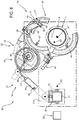
- Manipulator 23 comprises a guide system 37 designed to guide extrusion die 27 along an annular path; an articulated mechanism 38 for moving guide system 37 selectively between a work position around pipeline 1 ( Figure 7 ), and a rest position relatively distant from pipeline 1 ( Figure 5 ); and a slide 39 mounted on frame 21 and movable selectively along frame 21 in direction D2.
- guide system 37 comprises :
- supporting structure 40 is connected to articulated system 38 by a universal joint 50 and two actuators 51 and 52.
- supporting structure 40 supports extrusion device 26 ( Figure 7 ) and winder 46, which comprises a rotary joint 53 and a reel 54 which rotates about a rotation axis A2.
- Rotary joint 53 and reel 54 are aligned along rotation axis A2.
- Rotary joint 53 comprises a fixed part connected to extrusion device 26; and a rotating portion integral with reel 54 and communicating with hose 29. Rotation of reel 54 about rotation axis A2 is powered, reversible, and coordinated with the movement of carriage 47.
- Reel 54 substantially comprises an annular seat 55 designed to wind at most one turn of hose 29, and which is coplanar with guide 41 and movable guide 43.
- guides 41 and 42 are arc-shaped and extend to an angle of over 180°; and movable guides 43 and 44 are complementary to respective guides 41 and 42, and so extend to an angle of less than 180°.
- Movable guides 43 and 44 open sufficiently to insert pipeline 1 between guides 41, 42 and movable guides 43, 44.
- guide 41 and movable guide 43 define an outer annular seat 56 designed to house hose 29.
- guides 41 and 42 and movable guides 43 and 44 define respective inner annular seats 57.
- Guide 42 and movable guide 44 support an annular rack 58, and a housing 59 for electric cables not shown in the attached drawings.
- carriage 47 comprises two facing, annular-sector-shaped plates 60; bars 61 connecting facing plates 60; rollers 62 which engage and are guided by inner annular seats 57 ( Figure 3 ); a pinion 63 which meshes with annular rack 58; an actuator 64 for activating pinion 63; and a control device 65.
- Extrusion die 27, roller 48, and lateral heaters 49 are mounted on carriage 47, between plates 60, so as to be movable selectively to and from pipeline 1 ( Figures 6 and 7 ).
- Extrusion die 27 is connected to a rotary joint 66 connectable to hose 29 ( Figure 8 ).
- guide system 37 is fitted around pipeline 1, and is centred with respect to pipeline 1 by spacers 67 allowing axial movement (in direction D1 parallel to longitudinal axis A1) of guide system 37 with respect to pipeline 1.
- Each spacer 67 preferably comprises a wheel with its axis crosswise to longitudinal axis A1. At least one of spacers 67 comprises a sensor 68 for determining the movement of guide system 37 with respect to pipeline 1 in direction D1.
- carriage 47 comprises a sensor 69 for identifying a reference such as, for example, annular weld bead 7.
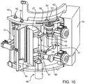
- Control system 24 ( Figures 6 and 7 ), control device 65 ( Figure 10 ), and sensor 69 provide for checking the correct axial position of guide system 37 along pipeline 1. If positioned wrongly, guide system 37 is moved along longitudinal axis A1 and centred with respect to cutback 8. Guide system 37 is preferably moved by moving the whole of manipulator 23 with respect to frame 21 in direction D2 by means of an actuator 70 ( Figure 7 ).
- the articulated system is operated by actuators (not shown) designed to determine the position of guide system 37 in a plane perpendicular to direction D2.
- actuators not shown
- work station 19 in addition to apparatus 20 for applying protective sheeting 9, work station 19 also comprises a cleaning apparatus 71 and a heating apparatus 72.
- Cleaning apparatus 71 comprises a manipulator 73; and an applicator 74 comprising two shells 75 for selectively closing applicator 74 around cutback 8.
- Heating apparatus 72 comprises a manipulator 76; and an applicator 77 comprising two shells 78 for selectively closing applicator 77 around cutback 8.
- Manipulators 73, 76 and shells 75, 78 provide for grit-blasting and induction heating in rapid succession, so as to prepare cutback 8 to adhere to protective sheeting 9 ( Figure 1 ).
- apparatus 20 is positioned well away from pipeline 1, so as not to interfere with apparatuses 71 and 72.
- plastifying device 25 is fed with polymer granules, and plastifies and transfers the material to tank 32 of extrusion device 26.
- manipulator 23 moves guide system 37, with movable guides 43 and 44 open, up to pipeline 1, to position guides 41, 42 and movable guides 43, 44 around pipeline 1.
- movable guides 43 and 44 are then closed to connect apparatus 20 to pipeline 1.
- actuators 51 and 52 are deactivated to allow universal joint 50 to move freely.
- guide system 37 centres automatically with respect to pipeline 1, by being freely orientable with respect to articulated system 38 supporting it.
- guide system 37 is positioned axially with respect to cutback 8, if necessary, so that the position of carriage 47 allows protective sheeting 9 to be positioned fairly accurately over the end portions of coatings 4.
- Extruding and applying protective sheeting 9 involve rotating carriage 47 over 360° around pipeline 1.
- the carriage is rotated 390° around pipeline 1 to achieve a wide overlap of the opposite ends of protective sheeting 9.
- lateral heaters 49 heat end portions 10 ( Figures 1, 2 and 3 ), and roller 48 presses protective sheeting 9 against pipeline 1 to ensure it adheres firmly to pipeline 1, and to prevent the formation of air bubbles.
- carriage 47 is restored to its starting position, by reversing it along the same path travelled to apply protective sheeting 9; during which movement, protective sheeting 9 may optionally be rolled further.
- hose 29 is guided by guide system 37 and winder 46.
- carriage 47 and extrusion die 27 are located on the opposite side to winder 46.
- hose 29 is housed inside outer annular seat 56, and is gathered inside annular seat 55 by powered reel 54 rotating clockwise about rotation axis A2, together with rotary hydraulic joint 53.
- carriage 47 is located at the point closest to winder 46, and hose 29 is wound almost completely around reel 54.
- carriage 47 is close to its limit position. To allow carriage 47 to reach this position, winder 46 has released most of the hose in time with the travel of carriage 47.
- Winder 46 tracks the reverse travel of carriage 47 to return carriage 47 and hose 29 to the configuration shown in Figure 11 .
- the apparatus, work station and method in the Claims also apply to substantially horizontal assembly lines on laying vessels equipped with S-laying ramps.
Landscapes
- Engineering & Computer Science (AREA)
- Mechanical Engineering (AREA)
- General Engineering & Computer Science (AREA)
- Manufacturing & Machinery (AREA)
- Physics & Mathematics (AREA)
- Thermal Sciences (AREA)
- Extrusion Moulding Of Plastics Or The Like (AREA)
- Lining Or Joining Of Plastics Or The Like (AREA)
- Shaping Of Tube Ends By Bending Or Straightening (AREA)
- Protection Of Pipes Against Damage, Friction, And Corrosion (AREA)
Applications Claiming Priority (2)
| Application Number | Priority Date | Filing Date | Title |
|---|---|---|---|
| IT002004A ITMI20132004A1 (it) | 2013-11-29 | 2013-11-29 | Apparecchiatura, stazione di lavoro e metodo per applicare un foglio protettivo di materiale polimerico a una tubazione e programma per elaboratore per attuare il metodo |
| PCT/IB2014/066430 WO2015079423A1 (en) | 2013-11-29 | 2014-11-28 | Apparatus, work station and method for applying protective sheeting of polymer material to a pipeline, and computer program for implementing the method |
Publications (2)
| Publication Number | Publication Date |
|---|---|
| EP3074687A1 EP3074687A1 (en) | 2016-10-05 |
| EP3074687B1 true EP3074687B1 (en) | 2018-07-18 |
Family
ID=49958566
Family Applications (1)
| Application Number | Title | Priority Date | Filing Date |
|---|---|---|---|
| EP14828295.7A Active EP3074687B1 (en) | 2013-11-29 | 2014-11-28 | Apparatus and method for applying protective sheeting of polymer material to a pipeline |
Country Status (8)
| Country | Link |
|---|---|
| US (1) | US10836097B2 (it) |
| EP (1) | EP3074687B1 (it) |
| AU (1) | AU2014356075B2 (it) |
| BR (1) | BR112016012143B1 (it) |
| CY (1) | CY1121463T1 (it) |
| IT (1) | ITMI20132004A1 (it) |
| RU (1) | RU2669096C1 (it) |
| WO (1) | WO2015079423A1 (it) |
Families Citing this family (3)
| Publication number | Priority date | Publication date | Assignee | Title |
|---|---|---|---|---|
| JP6353077B2 (ja) * | 2014-04-18 | 2018-07-04 | 華為技術有限公司Huawei Technologies Co.,Ltd. | リソース割り当て方法、リソースコンテンション方法、および関連する装置 |
| GB2581469A (en) * | 2018-11-16 | 2020-08-26 | Pipeline Technique Ltd | Tape winding apparatus and method |
| IL265226B (en) * | 2019-03-07 | 2020-11-30 | Azari Liron | An auxiliary winding device |
Family Cites Families (41)
| Publication number | Priority date | Publication date | Assignee | Title |
|---|---|---|---|---|
| US1969947A (en) * | 1931-02-28 | 1934-08-14 | Paraffine Co Inc | Pipe wrapping machine |
| GB987473A (en) * | 1961-06-22 | 1965-03-31 | Svenska Metallverken Ab | A method of producing insulated pipes |
| GB1054989A (it) * | 1964-09-17 | 1900-01-01 | ||
| US3547731A (en) * | 1968-02-12 | 1970-12-15 | Stuart Steel Protection Corp | Portable joint wrapper for pipelines |
| US3586582A (en) * | 1968-10-14 | 1971-06-22 | Crane Packing Co | Tape position control |
| US3660890A (en) * | 1969-07-28 | 1972-05-09 | Johns Manville | Method for jacketing cylindrical articles |
| US3671362A (en) * | 1970-03-30 | 1972-06-20 | Inland Systems Inc | Wall covering applicator |
| US3755039A (en) * | 1971-04-26 | 1973-08-28 | Johns Manville | Method of slitting and jacketing cylindrical bodies |
| US3984906A (en) * | 1974-05-10 | 1976-10-12 | The Dow Chemical Company | Sheet wrapper |
| US4007705A (en) * | 1974-12-20 | 1977-02-15 | Dnd Corporation | Apparatus for treating a cylindrical object |
| US4061513A (en) * | 1976-12-20 | 1977-12-06 | Danielson Carl G | Wrapping apparatus for pipeline joints |
| US4096017A (en) * | 1977-02-18 | 1978-06-20 | H. C. Price Co. | Method and article for forming field joints on pipe coated with thermoplastic material |
| US4113545A (en) * | 1977-07-29 | 1978-09-12 | Stuart Steel Protection Corporation | Pipe joint wrapping machine |
| IT1212747B (it) * | 1983-06-03 | 1989-11-30 | Ates Componenti Elettron | Attrezzatura per il rivestimento e taglio a filo di una pellicola plastica protettica delle fette di silicio per la lappatura finale. |
| US4574023A (en) * | 1984-01-26 | 1986-03-04 | Raychem Corporation | Apparatus and method for applying sleeves to pipe |
| US5118374A (en) * | 1990-09-26 | 1992-06-02 | Evans Rotork, Inc. | Method and apparatus for wrapping a laminate |
| EP0630316B1 (en) * | 1992-03-09 | 1998-01-07 | N.V. Raychem S.A. | Method for applying material to an elongate substrate |
| US5273611A (en) * | 1992-05-04 | 1993-12-28 | Sig-A-Rap | Apparatus for applying a continuous film to a pipeline |
| US5792308A (en) * | 1996-02-01 | 1998-08-11 | Compensating Tension Controls, Inc. | Apparatus for applying an adhesive coated tape on a core mounted on a mandrel |
| US6059319A (en) * | 1998-04-21 | 2000-05-09 | Floatec Corporation | Apparatus for forming field joints on plastic coated pipe |
| IT1304396B1 (it) * | 1998-11-25 | 2001-03-15 | Socotherm S R L | Metodo per la protezione anticorrosiva in campo dei giunti disaldatura e/o delle zone di rivestimento danneggiate di tubazioni |
| US6626376B1 (en) * | 2001-06-14 | 2003-09-30 | Airtech Spray Systems, Inc. | Spray coating device |
| DE10339067B4 (de) * | 2003-08-26 | 2005-08-18 | Daimlerchrysler Ag | Verfahren und Vorrichtung zum automatisierten Applizieren von Lackfolie auf Karosserieteile |
| JP2005349830A (ja) * | 2004-06-09 | 2005-12-22 | Reifenhaeuser Gmbh & Co Mas Fab | チューブ状フィルムの押出機構で用いられるターニングバーを用いた分岐装置 |
| CN101094958A (zh) * | 2004-10-12 | 2007-12-26 | 3M创新有限公司 | 压膜车及压膜方法 |
| ITGE20060031A1 (it) | 2006-03-08 | 2007-09-09 | Socotherm S P A | Metodo di rivestimento anticorrosione e termoisolante di corpi tubolari e di condotte di trasporto di fluidi ed apparato per l'attuazione di tale metodo. |
| BRPI0711496A2 (pt) * | 2006-06-05 | 2012-02-14 | 3M Innovative Properties Co | métodos para revestimento de uma junta de tubulação |
| ITMI20062402A1 (it) | 2006-12-14 | 2008-06-15 | Saipem Spa | Metodo e apparecchiatura di giunzione di spezzoni di tubo per realizzare tubazioni sottomarine e natante di posa di tubazioni sottomarine comprendente tale apparecchiatura |
| ITMI20070414A1 (it) * | 2007-03-02 | 2008-09-03 | Saipem Spa | Metodo e apparecchiatura per realizzare uno strato protettivo attorno ad una porzione anulare di giunzione fra spezzoni di tubo atti a realizzare una tubazione subacquea e natante di posa di tubazioni subacquee comprendente tale apparecchiatura |
| ES2363612T3 (es) | 2007-04-25 | 2011-08-10 | Oy Kwh Pipe Ab | Método y aparato para revestir tuberías. |
| EP2181832B1 (en) * | 2008-10-29 | 2012-06-27 | Oy KWH Pipe AB | Method and apparatus for coating pipes and pipe sections |
| EP2298455A1 (en) | 2009-09-17 | 2011-03-23 | Borealis AG | Method of coating pipes or pipe sections |
| EP2298531A1 (en) | 2009-09-17 | 2011-03-23 | Oy KWH Pipe AB | Apparatus and method for coating pipes or pipe sections |
| SE535040C2 (sv) * | 2010-04-22 | 2012-03-20 | Pronova Ab | Förfarande och anordning för tillverkning av ett sammanhängande påsformigt förpackningsämne |
| WO2011137161A1 (en) * | 2010-04-27 | 2011-11-03 | Subsea Services International, Inc. | Pipe joint coating |
| EP2535639A1 (de) | 2011-06-17 | 2012-12-19 | Jordan Reflektoren GmbH & Co.KG | Leuchten-Reflektor sowie Vorrichtung zu dessen Herstellung |
| ITMI20111104A1 (it) * | 2011-06-17 | 2012-12-18 | Saipem Spa | Metodo e apparecchiatura per applicare un foglio protettivo di materiale polimerico a una tubazione |
| NL2008206C2 (en) * | 2012-01-31 | 2013-08-01 | Bluemarine Offshore Yard Service B V | Device and method for the coating of a surface area of a gap in the coating of a pipeline. |
| US9555578B2 (en) * | 2012-11-30 | 2017-01-31 | The Boeing Company | Transfer system and method for applying a film material to an elongate member |
| DE102013102984B4 (de) * | 2013-03-22 | 2015-01-22 | Leonhard Kurz Stiftung & Co. Kg | Folienprägeeinrichtung |
| ITMI20131739A1 (it) * | 2013-10-17 | 2015-04-18 | Saipem Spa | Rullo e metodo per comprimere un foglio protettivo di materiale polimerico attorno una tubazione |
-
2013
- 2013-11-29 IT IT002004A patent/ITMI20132004A1/it unknown
-
2014
- 2014-11-28 WO PCT/IB2014/066430 patent/WO2015079423A1/en not_active Ceased
- 2014-11-28 US US15/039,787 patent/US10836097B2/en active Active
- 2014-11-28 EP EP14828295.7A patent/EP3074687B1/en active Active
- 2014-11-28 AU AU2014356075A patent/AU2014356075B2/en active Active
- 2014-11-28 BR BR112016012143-0A patent/BR112016012143B1/pt active IP Right Grant
- 2014-11-28 RU RU2016125762A patent/RU2669096C1/ru active
-
2018
- 2018-10-05 CY CY20181101028T patent/CY1121463T1/el unknown
Non-Patent Citations (1)
| Title |
|---|
| None * |
Also Published As
| Publication number | Publication date |
|---|---|
| AU2014356075B2 (en) | 2019-01-17 |
| BR112016012143A2 (pt) | 2017-08-08 |
| BR112016012143B1 (pt) | 2021-01-05 |
| US10836097B2 (en) | 2020-11-17 |
| US20170001365A1 (en) | 2017-01-05 |
| AU2014356075A1 (en) | 2016-06-30 |
| RU2669096C1 (ru) | 2018-10-08 |
| CY1121463T1 (el) | 2020-05-29 |
| WO2015079423A1 (en) | 2015-06-04 |
| ITMI20132004A1 (it) | 2015-05-30 |
| EP3074687A1 (en) | 2016-10-05 |
Similar Documents
| Publication | Publication Date | Title |
|---|---|---|
| EP2535168B2 (en) | Method and device for applying protective sheeting of polymer material to a pipeline | |
| EP2535629B1 (en) | Pipe-joining method and apparatus for producing underwater pipelines, and underwater-pipeline-laying vessel comprising such an apparatus | |
| RU2637954C2 (ru) | Машина для очистки секции трубопровода | |
| EP3074687B1 (en) | Apparatus and method for applying protective sheeting of polymer material to a pipeline | |
| EP2903799B1 (en) | Method, device and work station for applying protective sheeting of polymer material to a pipeline, and computer program for implementing such a method | |
| US10688517B2 (en) | Apparatus and method for coating pipelines | |
| EP3847003B1 (en) | Machine and method for making a protective joint about an annular junction portion of a pipeline | |
| EP3870374B1 (en) | Flame coating machine and method | |
| CN120165332A (zh) | 一种老旧电缆自动修复机器人以及修复方法 |
Legal Events
| Date | Code | Title | Description |
|---|---|---|---|
| PUAI | Public reference made under article 153(3) epc to a published international application that has entered the european phase |
Free format text: ORIGINAL CODE: 0009012 |
|
| 17P | Request for examination filed |
Effective date: 20160525 |
|
| AK | Designated contracting states |
Kind code of ref document: A1 Designated state(s): AL AT BE BG CH CY CZ DE DK EE ES FI FR GB GR HR HU IE IS IT LI LT LU LV MC MK MT NL NO PL PT RO RS SE SI SK SM TR |
|
| AX | Request for extension of the european patent |
Extension state: BA ME |
|
| DAX | Request for extension of the european patent (deleted) | ||
| REG | Reference to a national code |
Ref country code: DE Ref legal event code: R079 Ref document number: 602014028855 Country of ref document: DE Free format text: PREVIOUS MAIN CLASS: F16L0058100000 Ipc: B29C0063060000 |
|
| RIC1 | Information provided on ipc code assigned before grant |
Ipc: B29C 63/06 20060101AFI20171218BHEP Ipc: B29C 47/02 20060101ALI20171218BHEP Ipc: F16L 13/02 20060101ALI20171218BHEP Ipc: F16L 58/18 20060101ALI20171218BHEP Ipc: B05B 13/04 20060101ALN20171218BHEP Ipc: F16L 1/20 20060101ALI20171218BHEP |
|
| GRAP | Despatch of communication of intention to grant a patent |
Free format text: ORIGINAL CODE: EPIDOSNIGR1 |
|
| INTG | Intention to grant announced |
Effective date: 20180202 |
|
| GRAS | Grant fee paid |
Free format text: ORIGINAL CODE: EPIDOSNIGR3 |
|
| GRAA | (expected) grant |
Free format text: ORIGINAL CODE: 0009210 |
|
| AK | Designated contracting states |
Kind code of ref document: B1 Designated state(s): AL AT BE BG CH CY CZ DE DK EE ES FI FR GB GR HR HU IE IS IT LI LT LU LV MC MK MT NL NO PL PT RO RS SE SI SK SM TR |
|
| REG | Reference to a national code |
Ref country code: GB Ref legal event code: FG4D |
|
| REG | Reference to a national code |
Ref country code: CH Ref legal event code: EP |
|
| REG | Reference to a national code |
Ref country code: IE Ref legal event code: FG4D |
|
| REG | Reference to a national code |
Ref country code: DE Ref legal event code: R096 Ref document number: 602014028855 Country of ref document: DE |
|
| REG | Reference to a national code |
Ref country code: AT Ref legal event code: REF Ref document number: 1018889 Country of ref document: AT Kind code of ref document: T Effective date: 20180815 |
|
| REG | Reference to a national code |
Ref country code: NL Ref legal event code: FP |
|
| REG | Reference to a national code |
Ref country code: NO Ref legal event code: T2 Effective date: 20180718 |
|
| REG | Reference to a national code |
Ref country code: LT Ref legal event code: MG4D |
|
| REG | Reference to a national code |
Ref country code: AT Ref legal event code: MK05 Ref document number: 1018889 Country of ref document: AT Kind code of ref document: T Effective date: 20180718 |
|
| PG25 | Lapsed in a contracting state [announced via postgrant information from national office to epo] |
Ref country code: RS Free format text: LAPSE BECAUSE OF FAILURE TO SUBMIT A TRANSLATION OF THE DESCRIPTION OR TO PAY THE FEE WITHIN THE PRESCRIBED TIME-LIMIT Effective date: 20180718 Ref country code: LT Free format text: LAPSE BECAUSE OF FAILURE TO SUBMIT A TRANSLATION OF THE DESCRIPTION OR TO PAY THE FEE WITHIN THE PRESCRIBED TIME-LIMIT Effective date: 20180718 Ref country code: BG Free format text: LAPSE BECAUSE OF FAILURE TO SUBMIT A TRANSLATION OF THE DESCRIPTION OR TO PAY THE FEE WITHIN THE PRESCRIBED TIME-LIMIT Effective date: 20181018 Ref country code: IS Free format text: LAPSE BECAUSE OF FAILURE TO SUBMIT A TRANSLATION OF THE DESCRIPTION OR TO PAY THE FEE WITHIN THE PRESCRIBED TIME-LIMIT Effective date: 20181118 Ref country code: AT Free format text: LAPSE BECAUSE OF FAILURE TO SUBMIT A TRANSLATION OF THE DESCRIPTION OR TO PAY THE FEE WITHIN THE PRESCRIBED TIME-LIMIT Effective date: 20180718 Ref country code: SE Free format text: LAPSE BECAUSE OF FAILURE TO SUBMIT A TRANSLATION OF THE DESCRIPTION OR TO PAY THE FEE WITHIN THE PRESCRIBED TIME-LIMIT Effective date: 20180718 Ref country code: PL Free format text: LAPSE BECAUSE OF FAILURE TO SUBMIT A TRANSLATION OF THE DESCRIPTION OR TO PAY THE FEE WITHIN THE PRESCRIBED TIME-LIMIT Effective date: 20180718 |
|
| PG25 | Lapsed in a contracting state [announced via postgrant information from national office to epo] |
Ref country code: HR Free format text: LAPSE BECAUSE OF FAILURE TO SUBMIT A TRANSLATION OF THE DESCRIPTION OR TO PAY THE FEE WITHIN THE PRESCRIBED TIME-LIMIT Effective date: 20180718 Ref country code: LV Free format text: LAPSE BECAUSE OF FAILURE TO SUBMIT A TRANSLATION OF THE DESCRIPTION OR TO PAY THE FEE WITHIN THE PRESCRIBED TIME-LIMIT Effective date: 20180718 Ref country code: AL Free format text: LAPSE BECAUSE OF FAILURE TO SUBMIT A TRANSLATION OF THE DESCRIPTION OR TO PAY THE FEE WITHIN THE PRESCRIBED TIME-LIMIT Effective date: 20180718 |
|
| REG | Reference to a national code |
Ref country code: GR Ref legal event code: EP Ref document number: 20180402783 Country of ref document: GR Effective date: 20190225 |
|
| REG | Reference to a national code |
Ref country code: DE Ref legal event code: R097 Ref document number: 602014028855 Country of ref document: DE |
|
| PG25 | Lapsed in a contracting state [announced via postgrant information from national office to epo] |
Ref country code: CZ Free format text: LAPSE BECAUSE OF FAILURE TO SUBMIT A TRANSLATION OF THE DESCRIPTION OR TO PAY THE FEE WITHIN THE PRESCRIBED TIME-LIMIT Effective date: 20180718 Ref country code: ES Free format text: LAPSE BECAUSE OF FAILURE TO SUBMIT A TRANSLATION OF THE DESCRIPTION OR TO PAY THE FEE WITHIN THE PRESCRIBED TIME-LIMIT Effective date: 20180718 Ref country code: EE Free format text: LAPSE BECAUSE OF FAILURE TO SUBMIT A TRANSLATION OF THE DESCRIPTION OR TO PAY THE FEE WITHIN THE PRESCRIBED TIME-LIMIT Effective date: 20180718 Ref country code: RO Free format text: LAPSE BECAUSE OF FAILURE TO SUBMIT A TRANSLATION OF THE DESCRIPTION OR TO PAY THE FEE WITHIN THE PRESCRIBED TIME-LIMIT Effective date: 20180718 |
|
| PLBE | No opposition filed within time limit |
Free format text: ORIGINAL CODE: 0009261 |
|
| STAA | Information on the status of an ep patent application or granted ep patent |
Free format text: STATUS: NO OPPOSITION FILED WITHIN TIME LIMIT |
|
| PG25 | Lapsed in a contracting state [announced via postgrant information from national office to epo] |
Ref country code: DK Free format text: LAPSE BECAUSE OF FAILURE TO SUBMIT A TRANSLATION OF THE DESCRIPTION OR TO PAY THE FEE WITHIN THE PRESCRIBED TIME-LIMIT Effective date: 20180718 Ref country code: SM Free format text: LAPSE BECAUSE OF FAILURE TO SUBMIT A TRANSLATION OF THE DESCRIPTION OR TO PAY THE FEE WITHIN THE PRESCRIBED TIME-LIMIT Effective date: 20180718 Ref country code: SK Free format text: LAPSE BECAUSE OF FAILURE TO SUBMIT A TRANSLATION OF THE DESCRIPTION OR TO PAY THE FEE WITHIN THE PRESCRIBED TIME-LIMIT Effective date: 20180718 |
|
| REG | Reference to a national code |
Ref country code: DE Ref legal event code: R119 Ref document number: 602014028855 Country of ref document: DE |
|
| 26N | No opposition filed |
Effective date: 20190423 |
|
| REG | Reference to a national code |
Ref country code: CH Ref legal event code: PL |
|
| PG25 | Lapsed in a contracting state [announced via postgrant information from national office to epo] |
Ref country code: LU Free format text: LAPSE BECAUSE OF NON-PAYMENT OF DUE FEES Effective date: 20181128 Ref country code: MC Free format text: LAPSE BECAUSE OF FAILURE TO SUBMIT A TRANSLATION OF THE DESCRIPTION OR TO PAY THE FEE WITHIN THE PRESCRIBED TIME-LIMIT Effective date: 20180718 |
|
| REG | Reference to a national code |
Ref country code: BE Ref legal event code: MM Effective date: 20181130 |
|
| REG | Reference to a national code |
Ref country code: IE Ref legal event code: MM4A |
|
| PG25 | Lapsed in a contracting state [announced via postgrant information from national office to epo] |
Ref country code: CH Free format text: LAPSE BECAUSE OF NON-PAYMENT OF DUE FEES Effective date: 20181130 Ref country code: SI Free format text: LAPSE BECAUSE OF FAILURE TO SUBMIT A TRANSLATION OF THE DESCRIPTION OR TO PAY THE FEE WITHIN THE PRESCRIBED TIME-LIMIT Effective date: 20180718 Ref country code: LI Free format text: LAPSE BECAUSE OF NON-PAYMENT OF DUE FEES Effective date: 20181130 |
|
| PG25 | Lapsed in a contracting state [announced via postgrant information from national office to epo] |
Ref country code: IE Free format text: LAPSE BECAUSE OF NON-PAYMENT OF DUE FEES Effective date: 20181128 Ref country code: DE Free format text: LAPSE BECAUSE OF NON-PAYMENT OF DUE FEES Effective date: 20190601 |
|
| PG25 | Lapsed in a contracting state [announced via postgrant information from national office to epo] |
Ref country code: BE Free format text: LAPSE BECAUSE OF NON-PAYMENT OF DUE FEES Effective date: 20181130 |
|
| PG25 | Lapsed in a contracting state [announced via postgrant information from national office to epo] |
Ref country code: MT Free format text: LAPSE BECAUSE OF NON-PAYMENT OF DUE FEES Effective date: 20181128 |
|
| PG25 | Lapsed in a contracting state [announced via postgrant information from national office to epo] |
Ref country code: TR Free format text: LAPSE BECAUSE OF FAILURE TO SUBMIT A TRANSLATION OF THE DESCRIPTION OR TO PAY THE FEE WITHIN THE PRESCRIBED TIME-LIMIT Effective date: 20180718 |
|
| PG25 | Lapsed in a contracting state [announced via postgrant information from national office to epo] |
Ref country code: PT Free format text: LAPSE BECAUSE OF FAILURE TO SUBMIT A TRANSLATION OF THE DESCRIPTION OR TO PAY THE FEE WITHIN THE PRESCRIBED TIME-LIMIT Effective date: 20180718 |
|
| PG25 | Lapsed in a contracting state [announced via postgrant information from national office to epo] |
Ref country code: MK Free format text: LAPSE BECAUSE OF NON-PAYMENT OF DUE FEES Effective date: 20180718 Ref country code: HU Free format text: LAPSE BECAUSE OF FAILURE TO SUBMIT A TRANSLATION OF THE DESCRIPTION OR TO PAY THE FEE WITHIN THE PRESCRIBED TIME-LIMIT; INVALID AB INITIO Effective date: 20141128 |
|
| P01 | Opt-out of the competence of the unified patent court (upc) registered |
Effective date: 20230420 |
|
| P02 | Opt-out of the competence of the unified patent court (upc) changed |
Effective date: 20231116 |
|
| PGFP | Annual fee paid to national office [announced via postgrant information from national office to epo] |
Ref country code: NL Payment date: 20251124 Year of fee payment: 12 |
|
| PGFP | Annual fee paid to national office [announced via postgrant information from national office to epo] |
Ref country code: GB Payment date: 20251125 Year of fee payment: 12 |
|
| PGFP | Annual fee paid to national office [announced via postgrant information from national office to epo] |
Ref country code: NO Payment date: 20251120 Year of fee payment: 12 |
|
| PGFP | Annual fee paid to national office [announced via postgrant information from national office to epo] |
Ref country code: IT Payment date: 20251121 Year of fee payment: 12 Ref country code: FI Payment date: 20251124 Year of fee payment: 12 |
|
| PGFP | Annual fee paid to national office [announced via postgrant information from national office to epo] |
Ref country code: FR Payment date: 20251124 Year of fee payment: 12 |
|
| PGFP | Annual fee paid to national office [announced via postgrant information from national office to epo] |
Ref country code: GR Payment date: 20251118 Year of fee payment: 12 |
|
| PGFP | Annual fee paid to national office [announced via postgrant information from national office to epo] |
Ref country code: CY Payment date: 20251118 Year of fee payment: 12 |