EP3074709B1 - Mikrokanal-wärmetauscher mit dualem arbeitszyklus - Google Patents
Mikrokanal-wärmetauscher mit dualem arbeitszyklus Download PDFInfo
- Publication number
- EP3074709B1 EP3074709B1 EP14784394.0A EP14784394A EP3074709B1 EP 3074709 B1 EP3074709 B1 EP 3074709B1 EP 14784394 A EP14784394 A EP 14784394A EP 3074709 B1 EP3074709 B1 EP 3074709B1
- Authority
- EP
- European Patent Office
- Prior art keywords
- tube
- tube bank
- bank
- heat exchanger
- flattened
- Prior art date
- Legal status (The legal status is an assumption and is not a legal conclusion. Google has not performed a legal analysis and makes no representation as to the accuracy of the status listed.)
- Active
Links
Images


Classifications
-
- F—MECHANICAL ENGINEERING; LIGHTING; HEATING; WEAPONS; BLASTING
- F28—HEAT EXCHANGE IN GENERAL
- F28D—HEAT-EXCHANGE APPARATUS, NOT PROVIDED FOR IN ANOTHER SUBCLASS, IN WHICH THE HEAT-EXCHANGE MEDIA DO NOT COME INTO DIRECT CONTACT
- F28D7/00—Heat-exchange apparatus having stationary tubular conduit assemblies for both heat-exchange media, the media being in contact with different sides of a conduit wall
- F28D7/0066—Multi-circuit heat-exchangers, e.g. integrating different heat exchange sections in the same unit or heat-exchangers for more than two fluids
- F28D7/0083—Multi-circuit heat-exchangers, e.g. integrating different heat exchange sections in the same unit or heat-exchangers for more than two fluids with units having particular arrangement relative to a supplementary heat exchange medium, e.g. with interleaved units or with adjacent units arranged in common flow of supplementary heat exchange medium
- F28D7/0091—Multi-circuit heat-exchangers, e.g. integrating different heat exchange sections in the same unit or heat-exchangers for more than two fluids with units having particular arrangement relative to a supplementary heat exchange medium, e.g. with interleaved units or with adjacent units arranged in common flow of supplementary heat exchange medium the supplementary medium flowing in series through the units
-
- F—MECHANICAL ENGINEERING; LIGHTING; HEATING; WEAPONS; BLASTING
- F28—HEAT EXCHANGE IN GENERAL
- F28D—HEAT-EXCHANGE APPARATUS, NOT PROVIDED FOR IN ANOTHER SUBCLASS, IN WHICH THE HEAT-EXCHANGE MEDIA DO NOT COME INTO DIRECT CONTACT
- F28D1/00—Heat-exchange apparatus having stationary conduit assemblies for one heat-exchange medium only, the media being in contact with different sides of the conduit wall, in which the other heat-exchange medium is a large body of fluid, e.g. domestic or motor car radiators
- F28D1/02—Heat-exchange apparatus having stationary conduit assemblies for one heat-exchange medium only, the media being in contact with different sides of the conduit wall, in which the other heat-exchange medium is a large body of fluid, e.g. domestic or motor car radiators with heat-exchange conduits immersed in the body of fluid
- F28D1/04—Heat-exchange apparatus having stationary conduit assemblies for one heat-exchange medium only, the media being in contact with different sides of the conduit wall, in which the other heat-exchange medium is a large body of fluid, e.g. domestic or motor car radiators with heat-exchange conduits immersed in the body of fluid with tubular conduits
- F28D1/0408—Multi-circuit heat exchangers, e.g. integrating different heat exchange sections in the same unit or heat exchangers for more than two fluids
- F28D1/0426—Multi-circuit heat exchangers, e.g. integrating different heat exchange sections in the same unit or heat exchangers for more than two fluids with units having particular arrangement relative to the large body of fluid, e.g. with interleaved units or with adjacent heat exchange units in common air flow or with units extending at an angle to each other or with units arranged around a central element
- F28D1/0435—Combination of units extending one behind the other
-
- F—MECHANICAL ENGINEERING; LIGHTING; HEATING; WEAPONS; BLASTING
- F25—REFRIGERATION OR COOLING; COMBINED HEATING AND REFRIGERATION SYSTEMS; HEAT PUMP SYSTEMS; MANUFACTURE OR STORAGE OF ICE; LIQUEFACTION SOLIDIFICATION OF GASES
- F25B—REFRIGERATION MACHINES, PLANTS OR SYSTEMS; COMBINED HEATING AND REFRIGERATION SYSTEMS; HEAT PUMP SYSTEMS
- F25B39/00—Evaporators; Condensers
-
- F—MECHANICAL ENGINEERING; LIGHTING; HEATING; WEAPONS; BLASTING
- F28—HEAT EXCHANGE IN GENERAL
- F28D—HEAT-EXCHANGE APPARATUS, NOT PROVIDED FOR IN ANOTHER SUBCLASS, IN WHICH THE HEAT-EXCHANGE MEDIA DO NOT COME INTO DIRECT CONTACT
- F28D1/00—Heat-exchange apparatus having stationary conduit assemblies for one heat-exchange medium only, the media being in contact with different sides of the conduit wall, in which the other heat-exchange medium is a large body of fluid, e.g. domestic or motor car radiators
- F28D1/02—Heat-exchange apparatus having stationary conduit assemblies for one heat-exchange medium only, the media being in contact with different sides of the conduit wall, in which the other heat-exchange medium is a large body of fluid, e.g. domestic or motor car radiators with heat-exchange conduits immersed in the body of fluid
- F28D1/04—Heat-exchange apparatus having stationary conduit assemblies for one heat-exchange medium only, the media being in contact with different sides of the conduit wall, in which the other heat-exchange medium is a large body of fluid, e.g. domestic or motor car radiators with heat-exchange conduits immersed in the body of fluid with tubular conduits
- F28D1/053—Heat-exchange apparatus having stationary conduit assemblies for one heat-exchange medium only, the media being in contact with different sides of the conduit wall, in which the other heat-exchange medium is a large body of fluid, e.g. domestic or motor car radiators with heat-exchange conduits immersed in the body of fluid with tubular conduits the conduits being straight
- F28D1/0535—Heat-exchange apparatus having stationary conduit assemblies for one heat-exchange medium only, the media being in contact with different sides of the conduit wall, in which the other heat-exchange medium is a large body of fluid, e.g. domestic or motor car radiators with heat-exchange conduits immersed in the body of fluid with tubular conduits the conduits being straight the conduits having a non-circular cross-section
- F28D1/05366—Assemblies of conduits connected to common headers, e.g. core type radiators
- F28D1/05391—Assemblies of conduits connected to common headers, e.g. core type radiators with multiple rows of conduits or with multi-channel conduits combined with a particular flow pattern, e.g. multi-row multi-stage radiators
-
- F—MECHANICAL ENGINEERING; LIGHTING; HEATING; WEAPONS; BLASTING
- F28—HEAT EXCHANGE IN GENERAL
- F28F—DETAILS OF HEAT-EXCHANGE AND HEAT-TRANSFER APPARATUS, OF GENERAL APPLICATION
- F28F1/00—Tubular elements; Assemblies of tubular elements
- F28F1/10—Tubular elements and assemblies thereof with means for increasing heat-transfer area, e.g. with fins, with projections, with recesses
- F28F1/12—Tubular elements and assemblies thereof with means for increasing heat-transfer area, e.g. with fins, with projections, with recesses the means being only outside the tubular element
- F28F1/126—Tubular elements and assemblies thereof with means for increasing heat-transfer area, e.g. with fins, with projections, with recesses the means being only outside the tubular element consisting of zig-zag shaped fins
-
- F—MECHANICAL ENGINEERING; LIGHTING; HEATING; WEAPONS; BLASTING
- F25—REFRIGERATION OR COOLING; COMBINED HEATING AND REFRIGERATION SYSTEMS; HEAT PUMP SYSTEMS; MANUFACTURE OR STORAGE OF ICE; LIQUEFACTION SOLIDIFICATION OF GASES
- F25B—REFRIGERATION MACHINES, PLANTS OR SYSTEMS; COMBINED HEATING AND REFRIGERATION SYSTEMS; HEAT PUMP SYSTEMS
- F25B39/00—Evaporators; Condensers
- F25B39/02—Evaporators
-
- F—MECHANICAL ENGINEERING; LIGHTING; HEATING; WEAPONS; BLASTING
- F25—REFRIGERATION OR COOLING; COMBINED HEATING AND REFRIGERATION SYSTEMS; HEAT PUMP SYSTEMS; MANUFACTURE OR STORAGE OF ICE; LIQUEFACTION SOLIDIFICATION OF GASES
- F25B—REFRIGERATION MACHINES, PLANTS OR SYSTEMS; COMBINED HEATING AND REFRIGERATION SYSTEMS; HEAT PUMP SYSTEMS
- F25B39/00—Evaporators; Condensers
- F25B39/04—Condensers
-
- F—MECHANICAL ENGINEERING; LIGHTING; HEATING; WEAPONS; BLASTING
- F25—REFRIGERATION OR COOLING; COMBINED HEATING AND REFRIGERATION SYSTEMS; HEAT PUMP SYSTEMS; MANUFACTURE OR STORAGE OF ICE; LIQUEFACTION SOLIDIFICATION OF GASES
- F25B—REFRIGERATION MACHINES, PLANTS OR SYSTEMS; COMBINED HEATING AND REFRIGERATION SYSTEMS; HEAT PUMP SYSTEMS
- F25B40/00—Subcoolers, desuperheaters or superheaters
- F25B40/02—Subcoolers
-
- F—MECHANICAL ENGINEERING; LIGHTING; HEATING; WEAPONS; BLASTING
- F25—REFRIGERATION OR COOLING; COMBINED HEATING AND REFRIGERATION SYSTEMS; HEAT PUMP SYSTEMS; MANUFACTURE OR STORAGE OF ICE; LIQUEFACTION SOLIDIFICATION OF GASES
- F25B—REFRIGERATION MACHINES, PLANTS OR SYSTEMS; COMBINED HEATING AND REFRIGERATION SYSTEMS; HEAT PUMP SYSTEMS
- F25B40/00—Subcoolers, desuperheaters or superheaters
- F25B40/06—Superheaters
-
- F—MECHANICAL ENGINEERING; LIGHTING; HEATING; WEAPONS; BLASTING
- F28—HEAT EXCHANGE IN GENERAL
- F28D—HEAT-EXCHANGE APPARATUS, NOT PROVIDED FOR IN ANOTHER SUBCLASS, IN WHICH THE HEAT-EXCHANGE MEDIA DO NOT COME INTO DIRECT CONTACT
- F28D21/00—Heat-exchange apparatus not covered by any of the groups F28D1/00 - F28D20/00
- F28D2021/0019—Other heat exchangers for particular applications; Heat exchange systems not otherwise provided for
- F28D2021/0068—Other heat exchangers for particular applications; Heat exchange systems not otherwise provided for for refrigerant cycles
-
- F—MECHANICAL ENGINEERING; LIGHTING; HEATING; WEAPONS; BLASTING
- F28—HEAT EXCHANGE IN GENERAL
- F28F—DETAILS OF HEAT-EXCHANGE AND HEAT-TRANSFER APPARATUS, OF GENERAL APPLICATION
- F28F2260/00—Heat exchangers or heat exchange elements having special size, e.g. microstructures
- F28F2260/02—Heat exchangers or heat exchange elements having special size, e.g. microstructures having microchannels
Definitions
- This invention relates generally to a transport refrigeration system.
- Refrigerant vapor compression systems are well known in the art. Air conditioners and heat pumps employing refrigerant vapor compression cycles are commonly used for cooling or cooling/heating air supplied to a climate-controlled comfort zone within a residence, office building, hospital, school, restaurant or other facility. Refrigerant vapor compression systems are also commonly used for cooling air or other secondary fluid to provide a refrigerated environment for food items and beverage products within, for instance, display cases in supermarkets, convenience stores, groceries, cafeterias, restaurants and other food service establishments.
- a transport refrigeration system is mounted behind or on the roof of the truck and is configured to maintain a controlled temperature environment within the cargo box of the truck.
- refrigerated trailers which are typically pulled behind a tractor cab, a transport refrigeration system is mounted generally to the front wall of the trailer and is configured to maintain a controlled temperature environment within the cargo box of the trailer.
- these refrigerant vapor compression systems include a compression device, a refrigerant heat rejection heat exchanger, an expansion device and a refrigerant heat absorption heat exchanger connected in serial refrigerant flow communication in a refrigerant vapor compression cycle.
- the refrigerant heat rejection heat exchanger functions as a condenser.
- the refrigerant heat rejection heat exchanger functions as a gas cooler.
- the refrigerant heat absorption heat exchanger functions as an evaporator.
- conventional refrigerant vapor compression systems sometimes include one or more refrigerant-to refrigerant heat exchangers, for example, an economizer heat exchanger or a suction line-to-liquid line heat exchanger, or air-to-refrigerant heat exchanger, such as a reheat heat exchanger, variable frequency drive cooler or an intercooler.
- refrigerant-to refrigerant heat exchangers for example, an economizer heat exchanger or a suction line-to-liquid line heat exchanger, or air-to-refrigerant heat exchanger, such as a reheat heat exchanger, variable frequency drive cooler or an intercooler.
- other heat exchangers such radiator or turbo-charger/super-charger cooler may be included.
- the refrigerant heat rejection heat exchanger and the refrigerant heat absorption heat exchanger used in such refrigerant vapor compression systems have been round tube and plate fin heat exchangers constituting a plurality of round tubes, disposed in a desired circuiting arrangement, with each circuit defining a refrigerant flow path extending between a pair of headers or manifolds.
- a round tube and plate fin heat exchanger with conventional round tubes will have a relatively small number of large flow area refrigerant flow paths extending between the headers.
- multi-channel tubes are being used in heat exchangers for refrigerant vapor compression systems.
- multi-channel heat exchanger constructions are referred to as microchannel or minichannel heat exchangers as well.
- Each multi-channel tube has a plurality of flow channels extending longitudinally in parallel relationship the length of the tube, each channel defining a small cross-sectional flow area refrigerant path.
- a heat exchanger with multi-channel tubes extending in parallel relationship between a pair of headers or manifolds of the heat exchanger will define a relatively large number of small cross-sectional flow area refrigerant paths extending between the two headers.
- the headers which in some embodiments may be intermediate manifolds, may be divided into a number of chambers, which depends on a desired number of refrigerant passes.
- Conventional refrigeration applications such as a transport refrigeration system for example, include a plurality of separate heat exchangers. Each of these heat exchangers includes different design requirements and is manufactured separately prior to being installed into the heat exchanger assembly. These heat exchangers may be constructed as single slab micro-channel heat exchangers. US 2012/0080173 discloses a heat exchanger assembly with two banks. As a result, the increased design complexity, additional components and installation time required to assemble and integrate the heat exchangers into the system increase the cost of the assembly significantly. Therefore a more simplified, cost effective and thermally advanced multiple duty heat exchanger is required.
- the heat exchanger 20 includes a first tube bank 100 and a second tube bank 200.
- the second tube bank 200 is disposed behind the first tube bank 100 and is downstream with respect to an airflow, A, through the heat exchanger 20.
- the first tube bank 100 may also be referred to herein as the front heat exchanger slab 100 and the second tube bank 200 may also be referred to herein as the rear heat exchanger slab 200.
- the multi-bank heat exchanger 20 illustrated and described herein includes a first and second tube bank 100, 200, a heat exchanger 20 having any number of tube banks is within the scope of the invention.
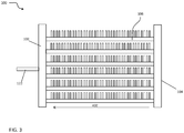
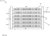
- the first tube bank 100 illustrated in FIGS. 3 and 3a , includes a first manifold 102, a second manifold 104 spaced apart from the first manifold 102, and a plurality of heat exchange tube segments 106, including at least a first and a second tube segment, extending longitudinally in spaced parallel relationship between and connecting the first manifold 102 and the second manifold 104 in fluid communication.
- the first tube bank 100 may be configured in a single pass arrangement such that fluid flows from the second manifold 104 to the first manifold 102 and an outlet 122 through the plurality of heat exchange tube segments 106, in the fluid flow direction indicated by arrow 402.
- FIG. 402. shown in FIG.
- the first tube bank 100 may be configured in a multi-pass flow arrangement.
- the first tube bank 100 generally includes a two-pass configuration. Fluid is configured to flow from the second manifold 104 to the first manifold 102 in the direction indicated by arrow 402 through a first, lower portion 106a of heat exchanger tube segments 106 and back to the second manifold 104 and outlet 122a through a second, upper portion 106b of heat exchanger tube segments 106, in the direction indicated by arrow 403.
- the second tube bank 200 includes a first manifold 202 ( FIG. 1 ) spaced apart from a second manifold 204 ( FIG. 1 ), and a plurality of heat exchange tube segments 206, including at least a first and a second tube segment.
- the first manifold 202 includes at least one baffle 105 such that the first manifold 202 is divided into a plurality of chambers, such as a chamber 203 and a chamber 205 for example.
- the second manifold 204 includes at least one baffle 105 such that the second manifold 204 also includes a plurality of chambers, such as chambers 207 and 209 for example.
- a first portion 206a of the plurality of tube segments 206 extends longitudinally in spaced parallel relationship between and fluidly connecting chamber 203 of the first manifold 202 with the chamber 207 of the second manifold 204 and a second portion 206b of the plurality of tube segments 206 extends longitudinally in spaced parallel relationship between and fluidly coupling chamber 205 of the first manifold 202 with chamber 209 of the second manifold 204.
- the multi-bank heat exchanger 20 illustrated and described herein includes a first portion 206a and a second portion 206b of heat exchanger tube segments, a heat exchanger 20 having any number of portions of heat exchanger tube segments 206 and a pair of chambers fluidly coupled to each portion is within the scope of the invention.
- Each set of manifolds 102, 202, 104, 204 disposed at either side of the heat exchanger 20 may comprise separate paired manifolds, may comprise separate chambers within an integral one-piece folded manifold assembly or may comprise separate chambers within an integral fabricated (e.g. extruded, drawn, rolled and welded) manifold assembly.
- Each tube bank 100, 200 may further include guard or "dummy" tubes (not shown) extending between its first and second manifolds at the top of the tube bank and at the bottom of the tube bank. These "dummy" tubes do not convey refrigerant flow, but add structural support to the tube bank and protect the uppermost and lowermost fins.
- each of the heat exchange tube segments 106, 206 comprises a flattened heat exchange tube having a leading edge 108, 208, a trailing edge 110, 210, an upper surface 112, 212, and a lower surface 114, 214.
- the leading edge 108, 208 of each heat exchange tube segment 106, 206 is upstream of its respective trailing edge 110, 210 with respect to airflow through the heat exchanger 20.
- the respective leading and trailing portions of the flattened tube segments 106, 206 are rounded thereby providing blunt leading edges 108, 208 and trailing edges 110, 210.
- the respective leading and trailing portions of the flattened tube segments 106, 206 may be formed in other configurations.
- each of the heat exchange tube segments 106, 206 of the first and second tube banks 100, 200, respectively, may be divided by interior walls into a plurality of discrete flow channels 120, 220 that extend longitudinally over the length of the tube segment 106, 206 from an inlet end to an outlet end and establish fluid communication between the respective manifolds 102, 104, 202, 204 of the first and the second tube banks 100, 200.
- the heat exchange tube segments 206 of the second tube bank 200 may have a width substantially equal to or different from the width of the tube segments 106 of the first tube bank 100.
- the tube segments 106 of the first tube bank 100 are wider than the tube segments 206 of the second tube bank 200 are within the scope of the invention.
- the interior flow passages of the wider heat exchange tube segments 206 may be divided into a greater number of discrete flow channels 220 than the number of discrete flow channels 120 into which the interior flow passages of the heat exchange tube segments 106 are divided.
- the flow channels 120, 220 may have a circular cross-section, a rectangular cross-section, a trapezoidal cross-section, a triangular cross-section or other non-circular cross-section.
- the heat exchange tube segments 106, 206 including the discrete flow channels 120, 220 may be formed using known techniques and materials, including, but not limited to, extruded or folded.
- the second tube bank 200 i.e. the rear heat exchanger slab, is disposed behind the first tube bank 100, i.e., the front heat exchanger slab, with respect to the airflow direction, with each heat exchange tube segment 106 directly aligned with a respective heat exchange tube segment 206 and with the leading edges 208 of the heat exchange tube segments 206 of the second tube bank 200 spaced from the trailing edges 110 of the heat exchange tube segments of the first tube bank 100 by a desired spacing, G.
- a spacer or a plurality of spacers disposed at longitudinally spaced intervals may be provided between the trailing edges 110 of the heat exchange tube segments 106 and the leading edges 208 of the heat exchange tube segments 206 to maintain the desired spacing, G, during assembly and brazing of the preassembled heat exchanger 20 in a brazed furnace.
- an elongated web 40 or a plurality of spaced web members 40 span the desired spacing gap, G, along at least of portion of the length of each aligned set of heat exchange tube segments 106, 206.
- the flattened tube finned heat exchanger 20 disclosed herein further includes a plurality of folded fins 320.
- Each folded fin 320 is formed from a plurality of connected strips or a single continuous strip of fin material tightly folded in a ribbon-like serpentine fashion thereby providing a plurality of closely spaced fins 322 that extend generally orthogonal to the flattened heat exchange tubes 106, 206.
- the fin density of the closely spaced fins 322 of each continuous folded fin 320 may be about 16 to 25 fins per inch, but higher or lower fin densities may also be used.
- each of the ribbon-like folded fin 320 extends at least from the leading edge 108 of the first tube bank 100 to the trailing edge of 210 of the second bank 200, and may overhang the leading edge 108 of the first tube bank 100 or/and trailing edge 208 of the second tube bank 200 if desired.
- each fin 322 of the folded fin 320 may be provided with louvers 330, 332 formed in the first and third sections, respectively, of each fin 322.
- a cooling media most commonly ambient air being moved by a fan, is configured to flow over the tube segments and fins 320 of the multiple bank, flattened tube heat exchanger 20 disclosed herein.
- the air is configured to flow through the airside of the heat exchanger 20 in the direction indicated by arrow "A" and passes over the outside surfaces of the heat exchange tube segments 106, 206 and the surfaces of the folded fin strips 320.
- the air flow first passes transversely across the upper and lower horizontal surfaces 112, 114 of the heat exchange tube segments 106 of the first tube bank 100, and then passes transversely across the upper and lower horizontal surfaces 212, 214 of the heat exchange tube segments 206 of the second tube bank 200.
- first portion 206a of heat exchange tube segments 206 is configured to receive a first fluid and the second portion 206b of heat exchange tube segments 206 is configured to receive a second fluid.
- each portion of heat exchanger tube segments may be configured to receive an additional fluid or receive the fluid from another portion either directly or after being circulated through a system component.
- the first fluid is configured to pass through the heat exchanger 20 in a cross-counterflow arrangement relative to the airflow, in that the first fluid provided to chamber 203 of manifold 202 via an inlet 221 passes through the first portion 206a of tube segments 206 of the second tube bank 200 to chamber 207 of the second manifold 204.
- Chamber 207 of the second manifolds 204 of the second tube bank 200 is fluidly coupled to the second manifold 104 of the first tube bank 100 such that the first fluid flows from the second tube bank 200 to the first tube bank 100 and then through at least a portion of the tube segments 106 of the first tube bank 100.
- the first fluid may be configured to flow through the first tube bank 100 in a single pass configuration indicated by arrow 402 ( FIG.
- the chamber 207 of second manifold 204 and a portion of second manifolds 104 may be integrally formed or may be separate manifolds connected by a conduit (not shown).
- the multiple tube bank, flattened tube finned heat exchanger 20 having a cross-counterflow circuit arrangement yields superior heat exchange performance, as compared to the crossflow or cross-parallel flow circuit arrangements, as well as allows for flexibility to manage the refrigerant side pressure drop via implementation of tubes of various widths within the first tube bank 100 and the second tube bank 200.
- the first fluid R may be a refrigerant flowing through a condenser, for example.
- the second fluid is configured to pass through the second tube bank 100 in a cross-flow arrangement relative to the airflow, indicated by arrow 405.
- the second fluid passes into the chamber 205 of manifold 202 of the second tube bank 200 through at least one inlet 223. From manifold 202, the second fluid flows through the second portion 206b of heat exchange tube segments 206, to chamber 209 of the second manifold 204 and outlet 222.
- the first fluid and the second fluid are approximately at the same temperature to minimize the cross-conduction effect, and therefore improve the performance of the heat exchanger 20.
- the first tube bank 100 and the second tube bank 200 are depicted with a certain flow configuration relative to the air flow A, other configurations are within the scope of the embodiment.
- the multiple bank flattened tube finned heat exchanger 20 may be integrated into a refrigeration system to improve the overall efficiency of the system.
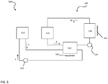
- a transport refrigeration system 500 configured to control conditions (i.e. temperature or humidity) associated with a mobile refrigerated cargo box, such as the cargo space of a truck, trailer, or container is provided.
- the transport refrigeration system 500 includes a transport refrigeration unit (TRU) 505 and a prime mover 510, such as a fuel-fired internal combustion engine for example.
- the prime mover 510 comprises a diesel engine equipped with a combustion air pressurization apparatus (not shown), such as a turbo-charger or a super-charger for example.
- the turbo-charger and super-charger are configured to boost the pressure of atmospheric air to supply pressurized combustion air for combusting fuel in the engine.
- the TRU 505 functions in a conventional manner to establish and regulate a desired product storage temperature within the refrigerated cargo space wherein perishable products, such as food, pharmaceuticals, and other temperature sensitive cargo for example, are stowed for transport.
- the TRU 505 includes a refrigeration compression device 515, a heat rejection heat exchanger 520, an expansion device 525, and a heat absorption heat exchanger 530 connected to form a closed loop refrigeration circuit.
- the TRU 505 also includes one or more fans 540, 545 associated with the heat rejection heat exchanger 520 and the heat absorption heat exchanger 530 respectively.
- the heat rejection heat exchanger 520 is a multiple bank flattened tube finned heat exchanger 20.
- the heat rejection heat exchanger 520 is also fluidly coupled to a second fluid circuit, such as a coolant circuit of the prime mover 510 for example.
- the heat rejection heat exchanger 520 may be configured to function in a manner similar to a radiator to reject the heat absorbed by the coolant from the prime mover 510.
- a pump 550 circulates coolant between the prime mover 510 and the heat rejection heat exchanger 520.
- other fluid circuits such as of a turbocharger, a variable frequency drive, or another auxiliary unit for example, may be fluidly and thermally coupled at a multiple bank flattened tube finned heat exchanger 20.
- the refrigerant R may be provided through inlet 221 to chamber 203 of the first manifold 202.
- the refrigerant is configured to pass through the first portion 206a of heat exchange tube segments 206 into chamber 207 of the second manifold 204.
- the refrigerant R is provided to the second manifold 104 of the first tube bank 100.
- the refrigerant R may then pass through the heat exchanger tube segments 106 of the first tube bank 100 in a first pass configuration to manifold 102 and outlet 122 ( FIG. 3 ).
- the refrigerant R may pass through the lower portion 106a of the tube segments 106 to the first manifold 102, and back to the second manifold 104, and outlet 122a, in a two-pass configuration ( FIG. 3a ). From either outlet 122 or outlet 122a, the refrigerant is returned to the refrigeration system.
- Coolant from the coolant circuit may be provided through inlet 223 to chamber 205 of the first manifold 202 of the second tube bank 200.
- the coolant C passes through the second portion 206b of the heat exchange tube segments 206 to chamber 209 of the second manifold 204, from where the coolant C is returned to the coolant circuit through at least one outlet 222.
- the coolant C in the second portion 206b of heat exchanger tube segments 206 may be configured to flow in either a single-pass or multi-pass flow arrangement.
- the first portion 206a of tube segments 206 of the second tube bank 200 is configured to de-superheat and initiate condensing of the refrigerant R and the second portion 206b of tube segments 206 of the second tube bank 200 is configured to cool the coolant C in place of a separate radiator.
- the first tube bank 100 of the heat exchanger 20 is dedicated to the condensing and sub-cooling of the refrigerant R. Such an arrangement prevents cross-conduction from the second slab 200 to the first slab 100, since hot desuperheating refrigerant R and hot engine coolant C are contained within the second slab 200 and have limited cross-conduction connection to the relatively cool condensing and subcooling refrigerant within the first slab 100.
- Other configurations where the flow of refrigerant R and coolant C through a multiple bank flattened tube finned heat exchanger 20 are reversed and still be considered within the scope of the embodiment.
- the TRU 505 of the transport refrigeration system 500 includes a second refrigerant compressor 555 having a second compression stage arranged between the first compressor 515, having a first compression stage, and the heat rejection heat exchanger 520.
- the refrigeration system 500 may include a single compressor having a first compression stage indicated by 515 and a second compression stage indicated by 555.
- the flow of refrigerant Ri from the first compressor 515 is configured to flow through a portion of the heat rejecting heat exchanger 520 before being supplied to the second compressor 555.
- the heat rejection heat exchanger 520 operates as an intercooler for the refrigerant Ri.
- the heat rejection heat exchanger 520 is fluidly coupled to the coolant circuit such that the refrigerant from the first compressor Ri, the refrigerant from the second compressor Rc and the coolant are all configured to flow through the heat rejection heat exchanger 520 simultaneously.
- the heat rejection heat exchanger 520 is a multiple bank flattened tube finned heat exchanger 20 and the second tube bank 200 includes three portions 206a, 206b, 206c of heat exchanger tube segments 206, each portion extending between a pair of opposite chambers 203, 205, 211, 207, 209, 213 arranged within the first and second manifold 202, 204 respectively.
- the refrigerant Rc from the second compressor 555 is provided through at least one inlet 221 to chamber 203 of the first manifold 202 and passes through the first portion 206a of heat exchanger tube segments 206 into chamber 207 of the second manifold 204. From the second manifold 204, the refrigerant Rc is provided to the first tube bank 100 where it flows in either a single pass or a multi-pass configuration (shown) and returns to the refrigerant system via outlet 122 or 122a respectively.
- the intercooler refrigerant Ri may be provided through at least one inlet 223 to chamber 205 of the first manifold 202 of the second tube bank 200.
- the intercooler refrigerant Ri passes through the second portion 206b of the heat exchange tube segments 206 to chamber 209 of the second manifold 204, from where the intercooler refrigerant Ri is provided to the second compressor 555 through outlet 222.
- the coolant C may be provided through inlet 225 to chamber 211 of the first manifold 202.
- the coolant C passes through the third portion 206c of the heat exchange tube segments 206 to chamber 213 of the second manifold 204 from where the coolant C is returned to the coolant circuit through at least one outlet 227.
- the refrigerant Rc from the second compressor 555 may be provided through an inlet 221 to chamber 203 of the first manifold 202 and pass through the first portion 206a of heat exchange tube segments 206 into chamber 207 of the second manifold 204. From the second manifold 204, the refrigerant Rc is provided to a chamber 126 of the second manifold 104 of the first tube bank 100. The refrigerant Rc passes through a first lower portion 106a of heat exchange tube segments 106 to chamber 130 of the first manifold 102 and is provided back to the refrigeration system 500 via an outlet 122.
- the coolant C may be provided through an inlet 223 to chamber 205 of the first manifold 202 of the second tube bank 200.
- the coolant C passes through the second portion 206b of the heat exchange tube segments 206 to chamber 209 of the second manifold 204, from where the coolant C is returned to the coolant circuit through at least one outlet 222.
- the intercooler refrigerant Ri from the first compressor 515 is provided through an inlet 136 to a chamber 128 of the second manifold 104 of the first tube bank 100.
- the intercooler refrigerant Ri is configured to flow through the second, upper portion 106b of heat exchange tube segments 106 to chamber 132 of the first manifold 102. From the first manifold102, the intercooler refrigerant is returned to the refrigerant system via outlet 138.
Landscapes
- Engineering & Computer Science (AREA)
- Physics & Mathematics (AREA)
- Thermal Sciences (AREA)
- Mechanical Engineering (AREA)
- General Engineering & Computer Science (AREA)
- Geometry (AREA)
- Heat-Exchange Devices With Radiators And Conduit Assemblies (AREA)
Claims (9)
- Transportkühlsystem, umfassend:eine Antriebsmaschine (510), welche einen Kühlkreislauf aufweist; undeine Transportkühleinheit (505), welche eine erste Kompressorstufe (515), eine zweite Kompressorstufe (555), einen Wärmeabgabewärmetauscher (520), eine Expansionseinrichtung (525) und einen Wärmeabsorptionswärmetauscher (530) beinhaltet, die verbunden ist, um einen geschlossenen Kühlkreislauf zu bilden,wobei der Wärmeabgabewärmetauscher (520) Folgendes umfasst:ein erstes Rohrbündel (100), welches mindestens ein erstes (106) und ein zweites abgeflachtes Rohrsegment beinhaltet, die sich in Längsrichtung in einer beabstandeten, parallelen Beziehung erstrecken;ein zweites Rohrbündel (200), welches mindestens eine erste Gruppe (206a) von abgeflachten Rohrsegmenten (206) und eine zweite Gruppe (206b) von abgeflachten Rohrsegmenten beinhaltet, die sich in Längsrichtung in einer beabstandeten, parallelen Beziehung erstrecken, wobei das zweite Rohrbündel (200) hinter dem ersten Rohrbündel (100) angeordnet ist, wobei ein Vorderende (208) des zweiten Rohrbündels (200) von einem Hinterende (110) des ersten Rohrbündels (100) beabstandet ist, wobei die erste Gruppe von abgeflachten Rohrsegmenten (206) mit dem ersten Rohrbündel (100) fluidisch gekoppelt ist und dazu konfiguriert ist, ein Kältemittel (RC) von der zweiten Kompressorstufe (555) aufzunehmen, und wobei die zweite Gruppe (206b) von abgeflachten Rohrsegmenten dazu konfiguriert ist, ein Kühlmittel (C) aufzunehmen, wobei die zweite Gruppe (206b) von abgeflachten Rohrsegmenten in Fluidkommunikation mit dem Kühlmittelkreislauf steht;wobei das erste Rohrbündel (100) oder das zweite Rohrbündel (200) ferner eine weitere Gruppe von abgeflachten Rohrsegmenten umfasst, wobei die weitere Gruppe von abgeflachten Rohrsegmenten dazu konfiguriert ist, ein Zwischenkühler-Kältemittel (RI) von der ersten Kompressorstufe (515) zu empfangen, bevor es zu der zweiten Kompressorstufe (555) weitergeleitet wird; undeinen Ventilator (520), der dazu konfiguriert ist, einen Luftstrom sequenziell über das erstes Rohrbündel (100) und das zweite Rohrbündel (200) bereitzustellen.
- Transportkühlsystem nach Anspruch 1, wobei das Kältemittel (RC) der zweiten Kompressorstufe (555) dazu konfiguriert ist, in einer Kreuzgegenströmungsrichtung bezogen auf den Luftstrom (A) durch die erste Gruppe von abgeflachten Rohrsegmenten (206) des zweiten Rohrbündels (200) und mindestens einen Bereich des abgeflachten Rohrsegments (106) des ersten Rohrbündels (100) zu strömen und wobei das Kühlmittel (C) dazu konfiguriert ist, in einer Kreuzströmungsrichtung bezogen auf den Luftstrom (A) durch die zweite Gruppe von abgeflachten Rohrsegmenten des zweiten Rohrbündels (200) zu strömen.
- Transportkühlsystem nach Anspruch 1, wobei das Kältemittel (RC) der zweiten Kompressorstufe (555) dazu konfiguriert ist, mindestens zwei Durchgänge zu machen, wobei mindestens ein Durchgang in der ersten Gruppe von abgeflachten Rohren (206) des zweiten Rohrbündels (200) bereitgestellt ist und mindestens ein Durchgang in dem ersten Rohrbündel (100) bereitgestellt ist.
- Transportkühlsystem nach Anspruch 3, wobei das Kältemittel (RC) der zweiten Kompressorstufe (555) dazu konfiguriert ist, mehr als einen Durchgang in dem ersten Rohrbündel (100) zu machen.
- Transportkühlsystem nach Anspruch 1, wobei das Kühlmittel (C) dazu konfiguriert ist, einen einzelnen Durchgang durch die zweite Gruppe von abgeflachten Rohren des zweiten Rohrbündels (200) zu machen.
- Transportkühlsystem nach Anspruch 1, wobei das Kühlmittel (C) dazu konfiguriert ist, eine Vielzahl von Durchgängen durch die zweite Gruppe von abgeflachten Rohren des zweiten Rohrbündels (200) zu machen.
- Transportkühlsystem nach Anspruch 1, wobei die abgeflachten Rohrsegmente des zweiten Rohrbündels (200) eine andere Breite aufweisen als die abgeflachten Rohrsegmente des ersten Rohrbündels.
- Transportkühlsystem nach Anspruch 1, wobei das Kühlmittel (C) eines ist von Wasser, Ethylenglykol und Propylenglykol.
- Transportkühlsystem nach Anspruch 1, wobei der Wärmetauscher dazu konfiguriert ist, als ein Zwischenkühler für das Kältemittel zu funktionieren, welches von der ersten Kompressorstufe (515) bereitgestellt ist.
Applications Claiming Priority (2)
| Application Number | Priority Date | Filing Date | Title |
|---|---|---|---|
| US201361908265P | 2013-11-25 | 2013-11-25 | |
| PCT/US2014/057147 WO2015076927A1 (en) | 2013-11-25 | 2014-09-24 | Dual duty microchannel heat exchanger |
Publications (2)
| Publication Number | Publication Date |
|---|---|
| EP3074709A1 EP3074709A1 (de) | 2016-10-05 |
| EP3074709B1 true EP3074709B1 (de) | 2021-04-28 |
Family
ID=51726866
Family Applications (1)
| Application Number | Title | Priority Date | Filing Date |
|---|---|---|---|
| EP14784394.0A Active EP3074709B1 (de) | 2013-11-25 | 2014-09-24 | Mikrokanal-wärmetauscher mit dualem arbeitszyklus |
Country Status (5)
| Country | Link |
|---|---|
| US (1) | US10337799B2 (de) |
| EP (1) | EP3074709B1 (de) |
| CN (1) | CN105765333B (de) |
| ES (1) | ES2877092T3 (de) |
| WO (1) | WO2015076927A1 (de) |
Families Citing this family (27)
| Publication number | Priority date | Publication date | Assignee | Title |
|---|---|---|---|---|
| EP2948724B1 (de) | 2013-01-28 | 2019-05-29 | Carrier Corporation | Wärmetauschereinheit mit mehreren rohrbündeln und einer verteileranordnung |
| EP3062037B1 (de) * | 2013-10-25 | 2020-07-15 | Mitsubishi Electric Corporation | Wärmetauscher und kältekreislaufvorrichtung mit diesem wärmetauscher |
| JP6520353B2 (ja) * | 2015-04-27 | 2019-05-29 | ダイキン工業株式会社 | 熱交換器及び空気調和機 |
| CN106288893A (zh) * | 2015-06-03 | 2017-01-04 | 丹佛斯微通道换热器(嘉兴)有限公司 | 换热器系统 |
| CN106679209A (zh) * | 2015-11-10 | 2017-05-17 | 丹佛斯微通道换热器(嘉兴)有限公司 | 制冷系统 |
| CN107388637B (zh) * | 2016-05-16 | 2023-04-28 | 丹佛斯微通道换热器(嘉兴)有限公司 | 换热器和换热模块 |
| EP3548333B1 (de) | 2016-12-02 | 2023-09-06 | Carrier Corporation | Frachttransportheizsystem |
| JP6766723B2 (ja) * | 2017-03-27 | 2020-10-14 | ダイキン工業株式会社 | 熱交換器又は冷凍装置 |
| US11415371B2 (en) * | 2017-03-27 | 2022-08-16 | Daikin Industries, Ltd. | Heat exchanger and refrigeration apparatus |
| EP3410053A1 (de) | 2017-05-30 | 2018-12-05 | ECOFLOW Sp. z o.o. | Luftgekühlter wärmetauscher |
| TWM550369U (zh) * | 2017-07-25 | 2017-10-11 | Cryomax Cooling System Corp | 水管加強連結片組 |
| CN109780756B (zh) * | 2017-11-13 | 2021-08-17 | 杭州三花微通道换热器有限公司 | 换热器、制冷系统及制冷设备 |
| US20190162455A1 (en) * | 2017-11-29 | 2019-05-30 | Lennox Industries, Inc. | Microchannel heat exchanger |
| CN108253820A (zh) * | 2018-01-12 | 2018-07-06 | 湘潭大学 | 一种用于甲醇燃料电池的多介质换热器 |
| US10712095B2 (en) | 2018-02-14 | 2020-07-14 | Lennox Industries Inc. | Heat exchanger construction |
| WO2019223612A1 (zh) * | 2018-05-23 | 2019-11-28 | 三花控股集团有限公司 | 一种热管理系统 |
| US11047625B2 (en) | 2018-05-30 | 2021-06-29 | Johnson Controls Technology Company | Interlaced heat exchanger |
| US11592215B2 (en) | 2018-08-29 | 2023-02-28 | Waterfurnace International, Inc. | Integrated demand water heating using a capacity modulated heat pump with desuperheater |
| CN109999602A (zh) * | 2019-03-15 | 2019-07-12 | 湖北楚天蓝环保设备工程有限公司 | 一种炼化企业VOCs回收处理装置及处理方法 |
| DE102019208619A1 (de) * | 2019-06-13 | 2020-12-17 | Siemens Aktiengesellschaft | Wärmetauscher, Verfahren zum Herstellen eines Wärmetauschers sowie Kraftwerk mit einem solchen Wärmetauscher |
| MX2021016125A (es) * | 2019-06-20 | 2022-05-30 | Algesacooling Pty Ltd | Dispositivo de transferencia térmica y sistemas de almacenamiento que incluyen el mismo. |
| CN111231611B (zh) * | 2020-02-24 | 2021-04-13 | 西安交通大学 | 一种双排微通道换热器空调器及其控制方法 |
| DE202020101967U1 (de) | 2020-04-09 | 2021-07-12 | Akg Verwaltungsgesellschaft Mbh | Verdampfer/Kondensator-Anordnung |
| CN112594979A (zh) * | 2020-12-15 | 2021-04-02 | 曾观来 | 一种汽车冷凝器 |
| US20230160638A1 (en) * | 2021-11-23 | 2023-05-25 | Polestar Performance Ab | Unified propulsion system and auxiliary radiator |
| DE102022208567A1 (de) * | 2022-08-18 | 2024-02-29 | Mahle International Gmbh | Rippeneinrichtung, Wärmeübertrager mit derselben sowie Verfahren zur Herstellung einer Rippeneinrichtung |
| US20250155173A1 (en) * | 2023-11-13 | 2025-05-15 | Mahle International Gmbh | System for controlling a defrost of a dual flow heat exchanger |
Citations (2)
| Publication number | Priority date | Publication date | Assignee | Title |
|---|---|---|---|---|
| US6523603B2 (en) * | 2000-08-30 | 2003-02-25 | Denso Corporation | Double heat exchanger with condenser and radiator |
| US20120080173A1 (en) * | 2010-10-04 | 2012-04-05 | Ford Global Technologies, Llc | Heat exchanger assembly having multiple heat exchangers |
Family Cites Families (122)
| Publication number | Priority date | Publication date | Assignee | Title |
|---|---|---|---|---|
| GB1355653A (en) | 1970-08-06 | 1974-06-05 | Babcock & Wilcox Ltd | Tube locating means |
| GB1492408A (en) | 1976-04-20 | 1977-11-16 | British Gas Corp | Heat exchangers |
| US4328861A (en) | 1979-06-21 | 1982-05-11 | Borg-Warner Corporation | Louvred fins for heat exchangers |
| EP0096127A1 (de) | 1982-06-14 | 1983-12-21 | Household Manufacturing, Inc. | Vorrichtung zum Kühlen von Motoren und zum Klimatisieren von Fahrzeugen |
| DE3568860D1 (en) | 1984-09-18 | 1989-04-20 | Sharp Kk | Solar heat collector system |
| EP0330701A3 (de) | 1984-09-18 | 1989-10-04 | Sharp Kabushiki Kaisha | Wärme-Kollektor |
| US4770240A (en) | 1985-05-13 | 1988-09-13 | Stark Manufacturing, Inc. | Manifold for a heat exchanger |
| US4736597A (en) | 1987-04-08 | 1988-04-12 | Thermo King Corporation | Transport refrigeration system |
| DE3938842A1 (de) | 1989-06-06 | 1991-05-29 | Thermal Waerme Kaelte Klima | Verfluessiger fuer ein kaeltemittel einer fahrzeugklimaanlage |
| JP2786702B2 (ja) | 1989-12-07 | 1998-08-13 | 昭和アルミニウム株式会社 | 複式一体型熱交換器 |
| US5046554A (en) | 1990-02-22 | 1991-09-10 | Calsonic International, Inc. | Cooling module |
| US5058662A (en) | 1990-09-26 | 1991-10-22 | General Motors Corporation | Multi tube heat exchanger with integral tube spacers and interlocks |
| US5186244A (en) | 1992-04-08 | 1993-02-16 | General Motors Corporation | Tube design for integral radiator/condenser |
| US5727618A (en) | 1993-08-23 | 1998-03-17 | Sdl Inc | Modular microchannel heat exchanger |
| US5348081A (en) | 1993-10-12 | 1994-09-20 | General Motors Corporation | High capacity automotive condenser |
| US5538079A (en) | 1994-02-16 | 1996-07-23 | Pawlick; Daniel R. | Heat exchanger with oblong grommetted tubes and locating plates |
| JP3044436B2 (ja) | 1994-04-21 | 2000-05-22 | 株式会社ゼクセル | 積層型熱交換器 |
| US5509199A (en) | 1995-01-17 | 1996-04-23 | General Motors Corporation | Method of making a dual radiator and condenser assembly |
| US5876667A (en) | 1996-01-11 | 1999-03-02 | Medtronic, Inc. | Blood heat exchange system employing micro-conduit |
| KR100210072B1 (ko) | 1996-07-09 | 1999-07-15 | 윤종용 | 공기조화기의 열교환기 |
| JPH10300271A (ja) | 1997-04-30 | 1998-11-13 | Nippon Light Metal Co Ltd | ヒートポンプ式冷暖房機の室外用熱交換器 |
| US5941303A (en) | 1997-11-04 | 1999-08-24 | Thermal Components | Extruded manifold with multiple passages and cross-counterflow heat exchanger incorporating same |
| JP4109746B2 (ja) | 1998-05-20 | 2008-07-02 | 昭和電工株式会社 | 一体型熱交換器 |
| EP0962736A3 (de) | 1998-06-01 | 2000-08-16 | Delphi Technologies, Inc. | Gewellte Rippe für Verdampfer mit verbesserter Kondensatabführung |
| DE19833845A1 (de) | 1998-07-28 | 2000-02-03 | Behr Gmbh & Co | Wärmeübertrager-Rohrblock und dafür verwendbares Mehrkammer-Flachrohr |
| US6189603B1 (en) | 1998-10-19 | 2001-02-20 | Denso Corporation | Double heat exchanger having condenser and radiator |
| DE19918616C2 (de) | 1998-10-27 | 2001-10-31 | Valeo Klimatechnik Gmbh | Verflüssiger zum Kondensieren des inneren Kältemittels einer Kraftfahrzeugklimatisierung |
| DE19920102B4 (de) * | 1999-05-03 | 2009-01-02 | Behr Gmbh & Co. Kg | Mehrkammerrohr und Wärmeübertrageranordnung für ein Kraftfahrzeug |
| US6449979B1 (en) | 1999-07-02 | 2002-09-17 | Denso Corporation | Refrigerant evaporator with refrigerant distribution |
| JP4281175B2 (ja) | 1999-09-29 | 2009-06-17 | 株式会社デンソー | 複式熱交換器 |
| JP4207331B2 (ja) | 1999-09-29 | 2009-01-14 | 株式会社デンソー | 複式熱交換器 |
| US6439300B1 (en) | 1999-12-21 | 2002-08-27 | Delphi Technologies, Inc. | Evaporator with enhanced condensate drainage |
| EP1167911B1 (de) | 2000-06-26 | 2013-12-25 | Keihin Thermal Technology Corporation | Verdampfer |
| KR100366451B1 (ko) | 2000-10-27 | 2002-12-31 | 주식회사 엘지이아이 | 냉장고의 일체형 듀얼튜브 증발기 |
| US6964296B2 (en) | 2001-02-07 | 2005-11-15 | Modine Manufacturing Company | Heat exchanger |
| GB2372560A (en) | 2001-02-24 | 2002-08-28 | Llanelli Radiators Ltd | Heat exchanger system |
| JP2002277180A (ja) * | 2001-03-16 | 2002-09-25 | Calsonic Kansei Corp | 一体型熱交換器のコア部構造 |
| CZ20032624A3 (cs) | 2001-03-29 | 2004-08-18 | Showaádenkoák@Ák | Sběrač pro využití u tepelných výměníkůŹ tepelný výměník a způsob jeho výroby |
| DE10150213A1 (de) | 2001-10-12 | 2003-05-08 | Erbsloeh Aluminium Gmbh | Stranggepreßtes Profil, insbesondere für Wärmetauscher |
| DE10158436A1 (de) * | 2001-11-29 | 2003-06-12 | Behr Gmbh & Co | Wärmetauscher |
| US6540016B1 (en) | 2002-02-28 | 2003-04-01 | Norsk Hydro | Method of forming heat exchanger tube ports and manifold therefor |
| FR2844041B1 (fr) * | 2002-08-28 | 2005-05-06 | Valeo Thermique Moteur Sa | Module d'echange de chaleur pour un vehicule automobile et systeme comportant ce module |
| JP4062033B2 (ja) | 2002-09-27 | 2008-03-19 | 株式会社デンソー | 熱交換器モジュール |
| FR2846733B1 (fr) * | 2002-10-31 | 2006-09-15 | Valeo Thermique Moteur Sa | Condenseur, notamment pour un circuit de cimatisation de vehicule automobile, et circuit comprenant ce condenseur |
| KR100493689B1 (ko) | 2002-12-11 | 2005-06-02 | 엘지전자 주식회사 | 마이크로 채널 열교환기 |
| US6895770B1 (en) | 2002-12-23 | 2005-05-24 | Kenneth J. Kaminski | Condensate secondary pan for a central air conditioning system |
| WO2005003668A2 (en) | 2003-01-28 | 2005-01-13 | Advanced Ceramics Research, Inc. | Microchannel heat exchangers and methods of manufacturing the same |
| EP1447636A1 (de) | 2003-02-11 | 2004-08-18 | Delphi Technologies, Inc. | Wärmetauscher |
| DE20303139U1 (de) | 2003-02-27 | 2003-06-18 | Behr GmbH & Co. KG, 70469 Stuttgart | Vorrichtung zur Wärmeübertragung |
| DE10315371A1 (de) | 2003-04-03 | 2004-10-14 | Behr Gmbh & Co. Kg | Wärmeübertrager |
| JP4124136B2 (ja) | 2003-04-21 | 2008-07-23 | 株式会社デンソー | 冷媒蒸発器 |
| AU2003255422A1 (en) | 2003-08-07 | 2005-02-25 | Norsk Hydro Asa | Heat exchanger comprising two manifolds |
| US20050072562A1 (en) | 2003-10-02 | 2005-04-07 | Hall Peter David | Heat exchanger tube assembly |
| DE102004058724B4 (de) | 2003-12-09 | 2018-11-15 | Denso Corporation | Wärmetauscher und Kühlmodul mit diesem |
| US7587340B2 (en) | 2004-01-15 | 2009-09-08 | Seidman Glenn R | Method and apparatus for selling with short-bidding on goods |
| US20080029256A1 (en) | 2004-01-28 | 2008-02-07 | Behr Gmbh & Co.Kg | Heat Exchanger, in Particular a Flat Pipe Evaporator for a Motor Vehicle Air Conditioning System |
| FR2867845B1 (fr) | 2004-03-16 | 2007-04-20 | Valeo Climatisation | Tubes d'echangeur de chaleur favorisant le drainage des condensats |
| US20050217839A1 (en) * | 2004-03-30 | 2005-10-06 | Papapanu Steven J | Integral primary and secondary heat exchanger |
| JP4232750B2 (ja) | 2004-06-10 | 2009-03-04 | 株式会社デンソー | ハイブリッド自動車用冷却システム |
| CN2709909Y (zh) | 2004-07-13 | 2005-07-13 | 成都希望电子研究所 | 一种列管式换热器的换热结构 |
| CN2754040Y (zh) | 2004-08-27 | 2006-01-25 | 四川同一科技发展有限公司 | 双管换热器 |
| US7500999B2 (en) * | 2004-09-01 | 2009-03-10 | Praxair Technology, Inc. | Catalytic reactor |
| FR2875896B1 (fr) | 2004-09-29 | 2017-11-24 | Valeo Thermique Moteur Sa | Intercalaire d'echange de chaleur pour un dispositif d'echange de chaleur |
| EP1657513B1 (de) | 2004-11-16 | 2008-01-02 | Sanden Corporation | Wärmetauscher |
| US7275394B2 (en) | 2005-04-22 | 2007-10-02 | Visteon Global Technologies, Inc. | Heat exchanger having a distributer plate |
| KR100697088B1 (ko) | 2005-06-09 | 2007-03-20 | 엘지전자 주식회사 | 공기조화기 |
| DE102005052683B4 (de) | 2005-10-27 | 2012-05-31 | Visteon Global Technologies Inc. | Mehrkanalflachrohr für Wärmeübertrager |
| DE102005058769B4 (de) | 2005-12-09 | 2016-11-03 | Modine Manufacturing Co. | Ladeluftkühler |
| JP4779641B2 (ja) | 2005-12-26 | 2011-09-28 | 株式会社デンソー | 複合型熱交換器 |
| US7669557B2 (en) | 2006-02-08 | 2010-03-02 | Toyota Jidosha Kabushiki Kaisha | Cooling device for vehicle |
| EP1840494A3 (de) | 2006-03-29 | 2011-03-16 | Erbslöh Aluminium GmbH | Wärmetauscherprofil |
| JP4811087B2 (ja) | 2006-03-31 | 2011-11-09 | 株式会社デンソー | 熱交換器 |
| KR100812500B1 (ko) | 2006-06-19 | 2008-03-11 | 주식회사 두원공조 | 복합 열교환기의 일체형 핀 |
| KR20080008542A (ko) | 2006-07-20 | 2008-01-24 | 한라공조주식회사 | 열교환기 헤더탱크 |
| DE102006033771A1 (de) | 2006-07-21 | 2008-01-24 | Modine Manufacturing Co., Racine | Wärmetauscher |
| KR101225597B1 (ko) | 2006-09-04 | 2013-01-24 | 한라공조주식회사 | 열교환기용 루버 핀 |
| WO2008038948A1 (en) | 2006-09-25 | 2008-04-03 | Korea Delphi Automotive Systems Corporation | Automotive heat exchanger to the unification of header and tank and fabricating method thereof |
| US20080073061A1 (en) | 2006-09-27 | 2008-03-27 | Rajen Dias | Variable depth microchannels |
| WO2008042368A1 (en) | 2006-09-28 | 2008-04-10 | Johnson Controls Technology Company | Microchannel heat exchanger |
| JP2008116107A (ja) | 2006-11-02 | 2008-05-22 | Daikin Ind Ltd | 熱交換器 |
| US7721794B2 (en) | 2007-02-09 | 2010-05-25 | Lennox Industries Inc. | Fin structure for heat exchanger |
| WO2008105760A2 (en) | 2007-02-27 | 2008-09-04 | Carrier Corporation | Multi-channel flat tube evaporator with improved condensate drainage |
| FR2913490A1 (fr) | 2007-03-07 | 2008-09-12 | Valeo Systemes Thermiques | Boite collectrice pour echangeur de chaleur,notamment pour evaporateur de vehicule automobile,echangeur de chaleur comportant une telle boite,et procede pour sa fabrication |
| US20080229580A1 (en) | 2007-03-23 | 2008-09-25 | Russell Charles Anderson | Method of manufacturing a brazed micro-channel cold plate heat exchanger assembly |
| KR101344514B1 (ko) * | 2007-06-20 | 2013-12-24 | 한라비스테온공조 주식회사 | 차량용 냉각 시스템 |
| DE102007035111A1 (de) | 2007-07-20 | 2009-01-29 | Visteon Global Technologies Inc., Van Buren | Vorratstank für Hochdruckkältemittel-Wärmeübertrager und Verfahren zur Herstellung eines Vorratstanks |
| US7942020B2 (en) | 2007-07-27 | 2011-05-17 | Johnson Controls Technology Company | Multi-slab multichannel heat exchanger |
| JP2009074751A (ja) * | 2007-09-21 | 2009-04-09 | Denso Corp | 複合型熱交換器 |
| US8353330B2 (en) | 2007-11-02 | 2013-01-15 | Halla Climate Control Corp. | Heat exchanger |
| WO2009078869A1 (en) | 2007-12-18 | 2009-06-25 | Carrier Corporation | Heat exchanger for shedding water |
| US20090173479A1 (en) | 2008-01-09 | 2009-07-09 | Lin-Jie Huang | Louvered air center for compact heat exchanger |
| CN101946137B (zh) * | 2008-02-19 | 2013-08-28 | 开利公司 | 制冷剂蒸汽压缩系统 |
| CN202013133U (zh) | 2008-02-22 | 2011-10-19 | 利厄伯特公司 | 热交换器和热交换器系统 |
| US20090211288A1 (en) | 2008-02-25 | 2009-08-27 | Carrier Corporation | Combination microchannel condenser and radiator mounting arrangement |
| CN101298951A (zh) | 2008-06-20 | 2008-11-05 | 清华大学 | 一种带自分液结构的穿片式微通道换热器 |
| CN201229094Y (zh) | 2008-06-20 | 2009-04-29 | 清华大学 | 带自分液结构的穿片式微通道换热器 |
| US8627881B2 (en) | 2008-08-15 | 2014-01-14 | Carrier Corporation | Heat exchanger fin including louvers |
| US20100071868A1 (en) | 2008-09-19 | 2010-03-25 | Nordyne Inc. | Hvac units, heat exchangers, buildings, and methods having slanted fins to shed condensation or for improved air flow |
| US8997845B2 (en) | 2009-03-17 | 2015-04-07 | Automotive Components Holdings, Llc | Heat exchanger with long and short fins |
| CN201387254Y (zh) | 2009-03-19 | 2010-01-20 | 美的集团有限公司 | 全铝微通道换热器 |
| US9455213B2 (en) | 2009-08-28 | 2016-09-27 | Raytheon Company | Architecture for gas cooled parallel microchannel array cooler |
| US8658419B2 (en) * | 2009-09-04 | 2014-02-25 | Abec, Inc. | Heat transfer baffle system and uses thereof |
| CN101660870B (zh) | 2009-09-16 | 2012-07-18 | 三花丹佛斯(杭州)微通道换热器有限公司 | 具有改进制冷剂分配性能的换热器 |
| SG179189A1 (en) | 2009-09-16 | 2012-04-27 | Carrier Corp | Free-draining finned surface architecture for a heat exchanger |
| US20110073292A1 (en) | 2009-09-30 | 2011-03-31 | Madhav Datta | Fabrication of high surface area, high aspect ratio mini-channels and their application in liquid cooling systems |
| WO2011042344A2 (en) | 2009-10-07 | 2011-04-14 | Arcelik Anonim Sirketi | Microchannel heat exchanger and the manufacturing method thereof |
| US8464782B2 (en) | 2009-10-20 | 2013-06-18 | Delphi Technologies, Inc. | Manifold fluid communication plate |
| CN101706225B (zh) | 2009-11-13 | 2011-12-21 | 三花丹佛斯(杭州)微通道换热器有限公司 | 换热器及其翅片、及包括该换热器的热交换装置 |
| WO2011069015A2 (en) | 2009-12-02 | 2011-06-09 | The Regents Of The University Of Colorado, A Body Corporate | Microchannel expanded heat exchanger |
| US20110139414A1 (en) | 2009-12-14 | 2011-06-16 | Delphi Technologies, Inc. | Low Pressure Drop Fin with Selective Micro Surface Enhancement |
| CN101839590B (zh) | 2010-02-22 | 2012-03-21 | 三花丹佛斯(杭州)微通道换热器有限公司 | 一种微通道换热器 |
| EP2372289B1 (de) | 2010-03-31 | 2018-11-14 | Modine Manufacturing Company | Wärmetauscher |
| US9989279B2 (en) * | 2010-04-29 | 2018-06-05 | Carrier Corporation | Refrigerant vapor compression system with intercooler |
| CN201764878U (zh) | 2010-08-05 | 2011-03-16 | 浙江金宸三普换热器有限公司 | 新型均配结构的平行流式换热器 |
| US20120168125A1 (en) | 2011-01-05 | 2012-07-05 | Tesla Motors, Inc. | Multi-Function Automotive Radiator and Condenser Airflow System |
| US8466162B2 (en) | 2011-01-26 | 2013-06-18 | Boehringer Ingelheim International Gmbh | 5-alkynyl-pyridines |
| US20120222848A1 (en) * | 2011-03-01 | 2012-09-06 | Visteon Global Technologies, Inc. | Integrated counter cross flow condenser |
| CN202109780U (zh) | 2011-05-30 | 2012-01-11 | 广州迪森家用锅炉制造有限公司 | 用于燃气采暖热水炉的管带式主换热器 |
| CN102243028B (zh) | 2011-07-08 | 2012-08-22 | 辽宁佰斯特热工设备制造有限公司 | 一种可拆式浮动盘管换热器 |
| CN202361699U (zh) | 2011-08-12 | 2012-08-01 | 力博特公司 | 带有加大的长形内容积的微通道热交换器 |
| EP2810010B1 (de) | 2012-02-02 | 2017-11-15 | Carrier Corporation | Mehrfachrohrbündelwärmetauscheranordnung und herstellungsverfahren |
| EP2948724B1 (de) | 2013-01-28 | 2019-05-29 | Carrier Corporation | Wärmetauschereinheit mit mehreren rohrbündeln und einer verteileranordnung |
-
2014
- 2014-09-24 EP EP14784394.0A patent/EP3074709B1/de active Active
- 2014-09-24 US US15/039,087 patent/US10337799B2/en active Active
- 2014-09-24 CN CN201480064112.1A patent/CN105765333B/zh not_active Expired - Fee Related
- 2014-09-24 WO PCT/US2014/057147 patent/WO2015076927A1/en not_active Ceased
- 2014-09-24 ES ES14784394T patent/ES2877092T3/es active Active
Patent Citations (2)
| Publication number | Priority date | Publication date | Assignee | Title |
|---|---|---|---|---|
| US6523603B2 (en) * | 2000-08-30 | 2003-02-25 | Denso Corporation | Double heat exchanger with condenser and radiator |
| US20120080173A1 (en) * | 2010-10-04 | 2012-04-05 | Ford Global Technologies, Llc | Heat exchanger assembly having multiple heat exchangers |
Also Published As
| Publication number | Publication date |
|---|---|
| ES2877092T3 (es) | 2021-11-16 |
| CN105765333B (zh) | 2019-01-04 |
| US20160290730A1 (en) | 2016-10-06 |
| WO2015076927A1 (en) | 2015-05-28 |
| US10337799B2 (en) | 2019-07-02 |
| CN105765333A (zh) | 2016-07-13 |
| EP3074709A1 (de) | 2016-10-05 |
Similar Documents
| Publication | Publication Date | Title |
|---|---|---|
| EP3074709B1 (de) | Mikrokanal-wärmetauscher mit dualem arbeitszyklus | |
| US10508862B2 (en) | Heat exchanger for air-cooled chiller | |
| US20200348088A1 (en) | Flattened tube finned heat exchanger and fabrication method | |
| US5186244A (en) | Tube design for integral radiator/condenser | |
| US7073570B2 (en) | Automotive heat exchanger | |
| CN105074375B (zh) | 层叠型热交换器 | |
| US5186246A (en) | Extruded coolant/refrigerant tank with separate headers | |
| US20170097179A1 (en) | Refrigeration system with integrated core structure | |
| US20130240186A1 (en) | Multiple Tube Bank Flattened Tube Finned Heat Exchanger | |
| JP2008503705A (ja) | 冷却システムで使用するための一体型の熱交換器 | |
| JP2000346568A (ja) | 熱交換器 | |
| JP2005510689A (ja) | 熱交換器 | |
| US6772602B2 (en) | Cooling system for a vehicle | |
| US9303925B2 (en) | Microchannel suction line heat exchanger | |
| CN107110568A (zh) | 多通路多板片折叠式微通道换热器 | |
| US11384988B2 (en) | Heat exchanger | |
| US11656033B2 (en) | Combined core microchannel heat exchanger | |
| US20190168582A1 (en) | Multi-temperature transportation refrigeration system | |
| US20170045299A1 (en) | Improved heat exchanger | |
| WO2016125437A1 (ja) | エジェクタ一体型熱交換器 | |
| US11820199B2 (en) | Heat exchanger | |
| US7650934B2 (en) | Heat exchanger | |
| US20140182326A1 (en) | Heat Exchanger For A Heating, Ventilation And/Or Air-Conditioning Unit | |
| KR101472368B1 (ko) | 열교환기 | |
| KR101650088B1 (ko) | 열교환기 |
Legal Events
| Date | Code | Title | Description |
|---|---|---|---|
| PUAI | Public reference made under article 153(3) epc to a published international application that has entered the european phase |
Free format text: ORIGINAL CODE: 0009012 |
|
| 17P | Request for examination filed |
Effective date: 20160621 |
|
| AK | Designated contracting states |
Kind code of ref document: A1 Designated state(s): AL AT BE BG CH CY CZ DE DK EE ES FI FR GB GR HR HU IE IS IT LI LT LU LV MC MK MT NL NO PL PT RO RS SE SI SK SM TR |
|
| AX | Request for extension of the european patent |
Extension state: BA ME |
|
| DAX | Request for extension of the european patent (deleted) | ||
| STAA | Information on the status of an ep patent application or granted ep patent |
Free format text: STATUS: EXAMINATION IS IN PROGRESS |
|
| 17Q | First examination report despatched |
Effective date: 20200520 |
|
| GRAP | Despatch of communication of intention to grant a patent |
Free format text: ORIGINAL CODE: EPIDOSNIGR1 |
|
| STAA | Information on the status of an ep patent application or granted ep patent |
Free format text: STATUS: GRANT OF PATENT IS INTENDED |
|
| INTG | Intention to grant announced |
Effective date: 20201116 |
|
| GRAS | Grant fee paid |
Free format text: ORIGINAL CODE: EPIDOSNIGR3 |
|
| GRAA | (expected) grant |
Free format text: ORIGINAL CODE: 0009210 |
|
| STAA | Information on the status of an ep patent application or granted ep patent |
Free format text: STATUS: THE PATENT HAS BEEN GRANTED |
|
| AK | Designated contracting states |
Kind code of ref document: B1 Designated state(s): AL AT BE BG CH CY CZ DE DK EE ES FI FR GB GR HR HU IE IS IT LI LT LU LV MC MK MT NL NO PL PT RO RS SE SI SK SM TR |
|
| REG | Reference to a national code |
Ref country code: GB Ref legal event code: FG4D |
|
| REG | Reference to a national code |
Ref country code: CH Ref legal event code: EP |
|
| REG | Reference to a national code |
Ref country code: AT Ref legal event code: REF Ref document number: 1387525 Country of ref document: AT Kind code of ref document: T Effective date: 20210515 |
|
| REG | Reference to a national code |
Ref country code: DE Ref legal event code: R096 Ref document number: 602014077013 Country of ref document: DE |
|
| REG | Reference to a national code |
Ref country code: IE Ref legal event code: FG4D |
|
| REG | Reference to a national code |
Ref country code: NL Ref legal event code: FP |
|
| REG | Reference to a national code |
Ref country code: LT Ref legal event code: MG9D |
|
| REG | Reference to a national code |
Ref country code: AT Ref legal event code: MK05 Ref document number: 1387525 Country of ref document: AT Kind code of ref document: T Effective date: 20210428 |
|
| PG25 | Lapsed in a contracting state [announced via postgrant information from national office to epo] |
Ref country code: HR Free format text: LAPSE BECAUSE OF FAILURE TO SUBMIT A TRANSLATION OF THE DESCRIPTION OR TO PAY THE FEE WITHIN THE PRESCRIBED TIME-LIMIT Effective date: 20210428 Ref country code: LT Free format text: LAPSE BECAUSE OF FAILURE TO SUBMIT A TRANSLATION OF THE DESCRIPTION OR TO PAY THE FEE WITHIN THE PRESCRIBED TIME-LIMIT Effective date: 20210428 Ref country code: FI Free format text: LAPSE BECAUSE OF FAILURE TO SUBMIT A TRANSLATION OF THE DESCRIPTION OR TO PAY THE FEE WITHIN THE PRESCRIBED TIME-LIMIT Effective date: 20210428 Ref country code: AT Free format text: LAPSE BECAUSE OF FAILURE TO SUBMIT A TRANSLATION OF THE DESCRIPTION OR TO PAY THE FEE WITHIN THE PRESCRIBED TIME-LIMIT Effective date: 20210428 Ref country code: BG Free format text: LAPSE BECAUSE OF FAILURE TO SUBMIT A TRANSLATION OF THE DESCRIPTION OR TO PAY THE FEE WITHIN THE PRESCRIBED TIME-LIMIT Effective date: 20210728 |
|
| REG | Reference to a national code |
Ref country code: ES Ref legal event code: FG2A Ref document number: 2877092 Country of ref document: ES Kind code of ref document: T3 Effective date: 20211116 |
|
| PG25 | Lapsed in a contracting state [announced via postgrant information from national office to epo] |
Ref country code: GR Free format text: LAPSE BECAUSE OF FAILURE TO SUBMIT A TRANSLATION OF THE DESCRIPTION OR TO PAY THE FEE WITHIN THE PRESCRIBED TIME-LIMIT Effective date: 20210729 Ref country code: IS Free format text: LAPSE BECAUSE OF FAILURE TO SUBMIT A TRANSLATION OF THE DESCRIPTION OR TO PAY THE FEE WITHIN THE PRESCRIBED TIME-LIMIT Effective date: 20210828 Ref country code: LV Free format text: LAPSE BECAUSE OF FAILURE TO SUBMIT A TRANSLATION OF THE DESCRIPTION OR TO PAY THE FEE WITHIN THE PRESCRIBED TIME-LIMIT Effective date: 20210428 Ref country code: PL Free format text: LAPSE BECAUSE OF FAILURE TO SUBMIT A TRANSLATION OF THE DESCRIPTION OR TO PAY THE FEE WITHIN THE PRESCRIBED TIME-LIMIT Effective date: 20210428 Ref country code: NO Free format text: LAPSE BECAUSE OF FAILURE TO SUBMIT A TRANSLATION OF THE DESCRIPTION OR TO PAY THE FEE WITHIN THE PRESCRIBED TIME-LIMIT Effective date: 20210728 Ref country code: PT Free format text: LAPSE BECAUSE OF FAILURE TO SUBMIT A TRANSLATION OF THE DESCRIPTION OR TO PAY THE FEE WITHIN THE PRESCRIBED TIME-LIMIT Effective date: 20210830 Ref country code: RS Free format text: LAPSE BECAUSE OF FAILURE TO SUBMIT A TRANSLATION OF THE DESCRIPTION OR TO PAY THE FEE WITHIN THE PRESCRIBED TIME-LIMIT Effective date: 20210428 Ref country code: SE Free format text: LAPSE BECAUSE OF FAILURE TO SUBMIT A TRANSLATION OF THE DESCRIPTION OR TO PAY THE FEE WITHIN THE PRESCRIBED TIME-LIMIT Effective date: 20210428 |
|
| PG25 | Lapsed in a contracting state [announced via postgrant information from national office to epo] |
Ref country code: SK Free format text: LAPSE BECAUSE OF FAILURE TO SUBMIT A TRANSLATION OF THE DESCRIPTION OR TO PAY THE FEE WITHIN THE PRESCRIBED TIME-LIMIT Effective date: 20210428 Ref country code: SM Free format text: LAPSE BECAUSE OF FAILURE TO SUBMIT A TRANSLATION OF THE DESCRIPTION OR TO PAY THE FEE WITHIN THE PRESCRIBED TIME-LIMIT Effective date: 20210428 Ref country code: DK Free format text: LAPSE BECAUSE OF FAILURE TO SUBMIT A TRANSLATION OF THE DESCRIPTION OR TO PAY THE FEE WITHIN THE PRESCRIBED TIME-LIMIT Effective date: 20210428 Ref country code: CZ Free format text: LAPSE BECAUSE OF FAILURE TO SUBMIT A TRANSLATION OF THE DESCRIPTION OR TO PAY THE FEE WITHIN THE PRESCRIBED TIME-LIMIT Effective date: 20210428 Ref country code: EE Free format text: LAPSE BECAUSE OF FAILURE TO SUBMIT A TRANSLATION OF THE DESCRIPTION OR TO PAY THE FEE WITHIN THE PRESCRIBED TIME-LIMIT Effective date: 20210428 Ref country code: RO Free format text: LAPSE BECAUSE OF FAILURE TO SUBMIT A TRANSLATION OF THE DESCRIPTION OR TO PAY THE FEE WITHIN THE PRESCRIBED TIME-LIMIT Effective date: 20210428 |
|
| REG | Reference to a national code |
Ref country code: DE Ref legal event code: R097 Ref document number: 602014077013 Country of ref document: DE |
|
| PLBE | No opposition filed within time limit |
Free format text: ORIGINAL CODE: 0009261 |
|
| STAA | Information on the status of an ep patent application or granted ep patent |
Free format text: STATUS: NO OPPOSITION FILED WITHIN TIME LIMIT |
|
| 26N | No opposition filed |
Effective date: 20220131 |
|
| REG | Reference to a national code |
Ref country code: CH Ref legal event code: PL |
|
| REG | Reference to a national code |
Ref country code: BE Ref legal event code: MM Effective date: 20210930 |
|
| PG25 | Lapsed in a contracting state [announced via postgrant information from national office to epo] |
Ref country code: IS Free format text: LAPSE BECAUSE OF FAILURE TO SUBMIT A TRANSLATION OF THE DESCRIPTION OR TO PAY THE FEE WITHIN THE PRESCRIBED TIME-LIMIT Effective date: 20210828 Ref country code: MC Free format text: LAPSE BECAUSE OF FAILURE TO SUBMIT A TRANSLATION OF THE DESCRIPTION OR TO PAY THE FEE WITHIN THE PRESCRIBED TIME-LIMIT Effective date: 20210428 Ref country code: AL Free format text: LAPSE BECAUSE OF FAILURE TO SUBMIT A TRANSLATION OF THE DESCRIPTION OR TO PAY THE FEE WITHIN THE PRESCRIBED TIME-LIMIT Effective date: 20210428 |
|
| PG25 | Lapsed in a contracting state [announced via postgrant information from national office to epo] |
Ref country code: LU Free format text: LAPSE BECAUSE OF NON-PAYMENT OF DUE FEES Effective date: 20210924 Ref country code: IT Free format text: LAPSE BECAUSE OF FAILURE TO SUBMIT A TRANSLATION OF THE DESCRIPTION OR TO PAY THE FEE WITHIN THE PRESCRIBED TIME-LIMIT Effective date: 20210428 Ref country code: IE Free format text: LAPSE BECAUSE OF NON-PAYMENT OF DUE FEES Effective date: 20210924 Ref country code: BE Free format text: LAPSE BECAUSE OF NON-PAYMENT OF DUE FEES Effective date: 20210930 |
|
| PG25 | Lapsed in a contracting state [announced via postgrant information from national office to epo] |
Ref country code: LI Free format text: LAPSE BECAUSE OF NON-PAYMENT OF DUE FEES Effective date: 20210930 Ref country code: CH Free format text: LAPSE BECAUSE OF NON-PAYMENT OF DUE FEES Effective date: 20210930 |
|
| PG25 | Lapsed in a contracting state [announced via postgrant information from national office to epo] |
Ref country code: HU Free format text: LAPSE BECAUSE OF FAILURE TO SUBMIT A TRANSLATION OF THE DESCRIPTION OR TO PAY THE FEE WITHIN THE PRESCRIBED TIME-LIMIT; INVALID AB INITIO Effective date: 20140924 |
|
| PG25 | Lapsed in a contracting state [announced via postgrant information from national office to epo] |
Ref country code: CY Free format text: LAPSE BECAUSE OF FAILURE TO SUBMIT A TRANSLATION OF THE DESCRIPTION OR TO PAY THE FEE WITHIN THE PRESCRIBED TIME-LIMIT Effective date: 20210428 |
|
| PGFP | Annual fee paid to national office [announced via postgrant information from national office to epo] |
Ref country code: NL Payment date: 20230822 Year of fee payment: 10 |
|
| PGFP | Annual fee paid to national office [announced via postgrant information from national office to epo] |
Ref country code: GB Payment date: 20230823 Year of fee payment: 10 |
|
| PGFP | Annual fee paid to national office [announced via postgrant information from national office to epo] |
Ref country code: FR Payment date: 20230822 Year of fee payment: 10 Ref country code: DE Payment date: 20230822 Year of fee payment: 10 |
|
| PGFP | Annual fee paid to national office [announced via postgrant information from national office to epo] |
Ref country code: ES Payment date: 20231002 Year of fee payment: 10 |
|
| PG25 | Lapsed in a contracting state [announced via postgrant information from national office to epo] |
Ref country code: MK Free format text: LAPSE BECAUSE OF FAILURE TO SUBMIT A TRANSLATION OF THE DESCRIPTION OR TO PAY THE FEE WITHIN THE PRESCRIBED TIME-LIMIT Effective date: 20210428 |
|
| PG25 | Lapsed in a contracting state [announced via postgrant information from national office to epo] |
Ref country code: TR Free format text: LAPSE BECAUSE OF FAILURE TO SUBMIT A TRANSLATION OF THE DESCRIPTION OR TO PAY THE FEE WITHIN THE PRESCRIBED TIME-LIMIT Effective date: 20210428 |
|
| PG25 | Lapsed in a contracting state [announced via postgrant information from national office to epo] |
Ref country code: MT Free format text: LAPSE BECAUSE OF FAILURE TO SUBMIT A TRANSLATION OF THE DESCRIPTION OR TO PAY THE FEE WITHIN THE PRESCRIBED TIME-LIMIT Effective date: 20210428 |
|
| REG | Reference to a national code |
Ref country code: DE Ref legal event code: R119 Ref document number: 602014077013 Country of ref document: DE |
|
| REG | Reference to a national code |
Ref country code: NL Ref legal event code: MM Effective date: 20241001 |
|
| GBPC | Gb: european patent ceased through non-payment of renewal fee |
Effective date: 20240924 |
|
| PG25 | Lapsed in a contracting state [announced via postgrant information from national office to epo] |
Ref country code: NL Free format text: LAPSE BECAUSE OF NON-PAYMENT OF DUE FEES Effective date: 20241001 |
|
| PG25 | Lapsed in a contracting state [announced via postgrant information from national office to epo] |
Ref country code: DE Free format text: LAPSE BECAUSE OF NON-PAYMENT OF DUE FEES Effective date: 20250401 |
|
| PG25 | Lapsed in a contracting state [announced via postgrant information from national office to epo] |
Ref country code: GB Free format text: LAPSE BECAUSE OF NON-PAYMENT OF DUE FEES Effective date: 20240924 |
|
| PG25 | Lapsed in a contracting state [announced via postgrant information from national office to epo] |
Ref country code: FR Free format text: LAPSE BECAUSE OF NON-PAYMENT OF DUE FEES Effective date: 20240930 |
|
| REG | Reference to a national code |
Ref country code: ES Ref legal event code: FD2A Effective date: 20251105 |
|
| PG25 | Lapsed in a contracting state [announced via postgrant information from national office to epo] |
Ref country code: ES Free format text: LAPSE BECAUSE OF NON-PAYMENT OF DUE FEES Effective date: 20240925 |