EP3074714B1 - Explosionsschutzelement - Google Patents
Explosionsschutzelement Download PDFInfo
- Publication number
- EP3074714B1 EP3074714B1 EP14805262.4A EP14805262A EP3074714B1 EP 3074714 B1 EP3074714 B1 EP 3074714B1 EP 14805262 A EP14805262 A EP 14805262A EP 3074714 B1 EP3074714 B1 EP 3074714B1
- Authority
- EP
- European Patent Office
- Prior art keywords
- blast
- protection element
- impact section
- apex
- facing surface
- Prior art date
- Legal status (The legal status is an assumption and is not a legal conclusion. Google has not performed a legal analysis and makes no representation as to the accuracy of the status listed.)
- Active
Links
Images


Classifications
-
- F—MECHANICAL ENGINEERING; LIGHTING; HEATING; WEAPONS; BLASTING
- F41—WEAPONS
- F41H—ARMOUR; ARMOURED TURRETS; ARMOURED OR ARMED VEHICLES; MEANS OF ATTACK OR DEFENCE, e.g. CAMOUFLAGE, IN GENERAL
- F41H7/00—Armoured or armed vehicles
- F41H7/02—Land vehicles with enclosing armour, e.g. tanks
- F41H7/04—Armour construction
- F41H7/042—Floors or base plates for increased land mine protection
Definitions
- the invention relates to a blast-protection element for a vehicle, a land vehicle, and a method of manufacturing a land vehicle.
- the blast-protection element is for increased protection against land mines and/or improvised explosive devices for armoured land vehicles as disclosed in US2013/0014635 A .
- Explosive devices such as improvised explosive devices (IED) and land mines pose a threat to armoured land vehicles.
- IED improvised explosive devices
- land mines pose a threat to armoured land vehicles.
- Such explosive devices are typically placed on the ground, just above ground level or can be buried. Encountering of an explosive device by a land vehicle can trigger the device to explode under the vehicle and thus an under-vehicle blast.
- Such a blast can cause injuries or death of passengers of the vehicle and damage to the vehicle and cargo.
- V-shaped hulls have been used for improved protection against IEDs.
- Stryker vehicles have been manufactured and retrofitted with a V-hull for improved performance against IEDs compared to the traditional flat-bottom configuration.
- the downward pointing V-shaped geometry is intended to deflect upward propagating blasts occurring under the vehicle.
- V-shaped (or diamond-shaped) hull design is disclosed in US-A-2007/0 186 762 .
- a disadvantage of V-shaped hulls is that a vehicle provided with such a hull generally has a higher centre of gravity of the vehicle, which increases the risk of roll-over of the vehicle.
- US-B-8 365 649 relates to a composite armour assembly having a convex downward-facing centre surface and concave downward-facing sides, in particular figures 1A and 4E .
- the major convex centre part results in worse pulse transfer and limited or no membrane forces under blast loading.
- US-A-2011/0 088 544 figure 3 , relates to an armour plate with side walls in the form of concave chutes, and a broad flat plate in the centre.
- WO-A-2008/127272 relates to a stepped V-shaped bottom hull for an armoured vehicle, in particular figures 1B and 2 .
- US-A-2012/0 247 315 describes a blast-protection element for a land vehicle having an exterior impact surface defining a cross-sectional profile defining a smooth continuous curve, wherein the exterior impact surface is convex.
- the blast-protection element is, when in use attached to the vehicle, oriented convexly relative to the ground plane.
- a disadvantage of such a blast-protection element is that it is almost horizontal next to its centreline. Blasts occurring near the centreline are thus not efficiently deflected sideward.
- US-A-2007/0 084 337 describes a vehicle under-structure comprising an inwardly bent downwardly concave armoured bottom plate mounted on a bottom of a vehicle, the bottom plate being formed with at least one bending edge extending longitudinally with respect to the vehicle.
- US-A-2003/0 010 189 describes a concave, homogenous protective floor plate having a large radius for an armoured vehicle.
- US-A-2011/0 314 999 disclosed a curved underbelly device for an armoured vehicle including curvilinear, saddle and sinusoidal shapes.
- Gurumurthy "Blast mitigation strategies for vehicles using shape optimization methods", master thesis MIT, September 2008, http://hdl.handle.net/1721.1/45759 , describes the 2D modelling of the flow of a blast wave around a vehicle with a vehicle hull, including a concave hull, simulated as a non-deformable solid object and having a half consisting of a quarter circle. It was observed that a V-shape showed the best performance over all blast intensity levels in terms of minimising the peak head-on impulse.
- BIPS 06/FEMA 426 Reference Manual to Mitigate Potential Terrorist Attacks against Buildings, 2nd Edition, October 2011 , describes that when an incident pressure wave impinges on a structure that is not parallel to the direction of the wave's travel, it is reflected and reinforced. This results in the structure being exposed to a reflected pressure that is greater than the incident pressure (or side-on pressure).
- the reflected pressure varies with the angle of incidence of the shock wave and is typical maximal when shock wave impinges on a perpendicular surface (angle of incidence of 0°), is minimum when the surface is parallel (angle of incidence 90°) and has a maximum due to Mach reflections around 45°.
- the coefficient of reflection is typically 2-13.
- An alternative approach to protect against blasts is to install suspended seats and energy absorbing materials.
- An objective of the present invention is to provide a blast-protection element that mitigates one or more of the above mentioned problems at least in part.
- the inventors found that this objective can at least in part be met by a blast-protection element having a specific design comprising concave elements.
- the invention relates to a blast-protection element for protecting a vehicle against a blast according to claim 1.
- the term "blast” as used in this application includes a shock-wave due to an explosion comprising highly compressed air, propagating radially outward from a source at supersonic velocities.
- blast-protection element refers to a device or part that serves as a protective cover or barrier for an object at one side of the blast-protection element against a blast (shockwave of an explosion) impacting the object.
- apex refers to a protruding part, such as an outward bulging extreme, for example a cusp or tip.
- An apex includes in particular a convex fold in an element wherein the fold extends as a line in a direction.
- An apex is typically not formed by a recess.
- smooth indicates that a surface is continuous and even. Such a surface typically lacks projections or indentations.
- concave refers to a surface that is curving inward as opposed to convex, at least in one direction.
- concave is not restricted to describing a surface with a constant radius of curvature, but rather is used to denote the general appearance of the surface.
- concave includes single concave (e.g. as in a hollow cylinder), a saddle curvature and double concave (e.g. as in a hollow sphere).
- transversal cross-section refers to a cross-section in the plane perpendicular to the longitudinal direction. Such cross-section is typically in the plane perpendicular to a line defined by the apex. Where a certain profile in a transversal cross-section is described, in principle such a profile in any cross-section will work.
- concave blast-guiding part profile section refers to a concave section of a transversal cross-sectional profile corresponding to a blast-guiding part of the blast-facing surface of the impact section
- deformable refers to deformation under blast conditions.
- deformable relates to objects and/or materials with a finite Young's modulus, typically a Young's modulus of 5 GPa to 500 GPa, for example 20 GPa to 230 GPa.
- a deformable object and/or material typically have a yield stress of 10 MPa to 5000 MPa, such as 180 MPa to 2000 MPa.
- a deformable object has a defined, finite ultimate strength that is higher than its yield stress by preferably at least 5% of the yield stress and typically is in the range of 30 MPa to 7000 MPa, such as 200 MPa to 2000 MPa. Nevertheless, fibre-reinforced materials not having a yield stress are also deformable materials.
- An important advantage of the blast-protection element is the improved stiffness when subjected to a blast load, due to the curved shape.
- a further advantage of the blast-protection element of the present invention is improved protection against blasts; resulting in reduced impulse transmitted to the vehicle and/or reduced deformation.
- the design of the blast-protection element allows deflecting a blast to the sides of the blast-protection element.
- An advantage of this is that secondary blast reflections from the ground are reduced.
- the design of the present invention allows reducing the reflected pressure at parts of the blast-protection elements close to the source of the blast by having an optimal angle of incidence at these parts.
- the blast-protection element combines the constructive response to a blast and the stiffness of a curved plate with a reduced reflected pressure at the apex.
- the choice of the angle at the apex allows a reduction of the coefficient of reflection from 10 to a lower value in the range of 3 to 5.
- the blast-protection element provides as additional advantage that deformation of the impact section at each side of the apex can be reduced.
- the impact section deforms less under the pressure wave of a blast, in comparison to a conventional flat or V-shaped blast-protection element, and to elements with large convex parts, and/or large non-concave centre parts.
- the main deformations of the blast-protection element according to the invention are primarily in the form of membrane deformations involving tensile stress (membrane stress) with limited shear stress and limited out-of-plane (plate) bending.
- the impact section acts preferably at least partially as a shell, resisting the blast at least partly by membrane action.
- the blast-protection element is suitable for a vehicle.
- the blast-protection element can comprise a vehicle floor or base plate; or can form a part thereof.
- the blast-protection element can be used for land-mine and/or IED protection for armoured land vehicles.
- the blast-protection element comprises an impact section.
- the impact section can comprises a part adapted for resisting and/or deflecting at least partly a blast, such as a blast occurring at least partly under a vehicle.
- the impact section is preferably massive and is preferably formed by a curved plate.
- the blast-protection element can comprise means for attaching the blast-protection element to a vehicle.
- the attachment can be for example demountable or permanent.
- the blast-protection element however may also form an integral part of a vehicle.
- the impact section comprises a blast-facing surface.
- the blast-facing surface can also be referred to as exterior surface.
- the blast-facing surface of the impact section comprises the blast-facing surface of the various parts of the impact section that have an exposed surface at the blast-facing side.
- the blast-facing surface is typically oriented towards the ground plane, in other words faces the ground.
- the impact section typically has an interior surface at an interior side opposed to a blast-facing surface at the blast-facing side.
- An object to be protected by the blast-protection element such as the vehicle cabin, is located at the interior side.
- the impact section typically comprises in addition an edge.
- the edge can comprise two opposed side edge parts and a front and rear side edge part opposed to each other. In use the edge parts can be positioned at the corresponding sides of the vehicle.
- the edge of the impact section typically defines a datum.
- the blast-protection element has a length, width and height and a corresponding longitudinal, transversal (lateral) and vertical direction and axis.
- the longitudinal direction extends parallel to the lengthwise axis of the vehicle (front-rear);
- the transversal or lateral direction extends perpendicular to the longitudinal direction and generally parallel to the ground plane and the vertical direction extends perpendicular to the ground plane.
- roll is around the longitudinal axis, pitch around the transversal axis and yaw around the vertical axis.
- the height of the blast-protection element refers to the maximal dimension (span) in vertical direction at the blast-facing side.
- the depth of impact section refers to the difference in vertical position between the interior side of the impact section and the side ends of the impact section.
- the impact section also has a thickness, measured in vertical direction.
- the width of the blast-protection element is preferably 200 cm to 300 cm, such as 2.1 m to 2.5 m.
- the length of the blast-protection element is typically 2 m to 8 m, such as 3 m to 6 m.
- the height of the blast-protection element, or impact section is typically 20 cm to 100 cm, such as 25 cm to 75 cm, such as 30 cm to 50 cm.
- the impact section comprises at least one apex part.
- the apex part comprises a blast-facing surface and comprises in its blast-facing surface a protruding apex.
- the impact section can comprise one, two or three apex parts or even more apex parts, each comprising an apex in the blast-facing surface.
- the apex part can be positioned at a centred transversal position of the impact section.
- An example of a centred transversal position of the impact section is between 40-60 % of the width of the impact section.
- an apex part extends in longitudinal direction, preferably over more than half of the length of the blast-protection element.
- an apex part is stiff, such as reinforced.
- An apex part extends over the thickness of the impact section and has preferably a larger thickness than the blast-guiding parts, such as 150 % or more or 200 % or more of the thickness of the blast-guiding parts.
- Such preferred apex part can provide a stiff spine of the blast-protection element.
- blast-facing surface of an apex part and/or an apex include convexly curved, flat and edged.
- An apex is typically formed by the part of the blast-facing surface of the impact section between the concave blast-facing surface portions of two blast-guiding parts.
- An apex part is preferably non-concave.
- An apex part preferably spans less than 5 % of the width of the impact section, such as 1 % or less. The apex is preferably sharp.
- an apex part comprises, or is formed by, a corner edge (such as a ridge) and the at least two blast-guiding parts are adjacent to the apex part, at opposed sides adjoined to each other at the corner edge.
- the corner edge can extend in longitudinal direction, preferably over a majority the length of the impact section, preferably over substantially the entire length (90 % or more) of the impact section.
- the corner edge can be straight and in longitudinal direction.
- the impact section can comprise only one edge.
- an apex part comprises two surfaces at angle in transversal direction and adjoined to each other at a corner edge extending in longitudinal direction, wherein in the surfaces are at an angle of 60° or less, such as 45° or less to the vertical direction.
- the impact section comprises at least two blast-guiding parts, such as two, three, four or more blast-guiding parts.
- the at least two blast-guiding parts extend at opposed sides of an apex part, preferably at two sides opposed in transversal direction.
- the blast-guiding parts can guide a blast at least partly to the (side) edges of the impact section and thus to sides of the blast-protection element. Accordingly, the blast-guiding parts can guide an under-vehicle blast at least partly to the sides of a vehicle.
- the blast-guiding parts and/or apex part can be structurally integrated, such as in case of a monolithic impact section.
- the blast-guiding parts and/or apex part can also be structurally separate elements of the impact section.
- the blast-guiding parts span the width of the impact section at least partly.
- the blast guiding parts in total span at least 75 % of the width of the impact section, preferably as 90 % or more, typically up to 95 % of the width. Accordingly, an apex part can be thin and span (in total for all apex parts) less than 25 % of the width of the impact section, such as 10 % or less or 5 % or less.
- the at least two blast-guiding parts each comprise a concave blast-facing surface portion. Accordingly, each of the at least two blast-guiding parts has a blast-facing surface comprising a portion that is concave. Both a concave blast-facing surface portion and an apex lie in a blast-facing surface of the impact section. A concave blast-facing surface portion accordingly lies at the same blast-facing side of the impact section as an apex.
- Each blast-guiding part comprises a concave blast-facing surface portion. More than 90 % of the blast-facing surface, of the blast-guiding part is concave, of each blast-guiding part. Preferably, substantially the entire blast facing surface is concave, preferably for each blast-guiding part.
- the concave curvature of the concave blast-facing surface portion provides as advantage over convex parts and over faceted blast-guiding parts with few facets and large kinks, that stress caused by the impact of a blast is dispersed in the blast-guiding part, as in a membrane.
- the concave blast-facing surface portion thus advantageously avoids concentration of shear stresses and stresses in edges.
- the loads are transferred in-plane to the sides of the blast-guiding parts.
- the concavity provides as advantage that, in use, the part of blast-facing surface close to the edge can have a large stand-off, allowing a blast to exit, while the blast-facing surface close to the apex can have an oblique angle to a blast that provides an advantageous reflection coefficient for a blast wave. In this way, design of the concave blast-facing surface portion can contribute to deflecting a blast occurring under a vehicle.
- a concave blast-facing surface portion thus has at least one osculating circle at the blast-facing side.
- a concave-blast facings surface portion has a radius of curvature in at least one direction.
- the osculating circle is preferably in the plane of a transversal cross-section (perpendicular to the longitudinal axis).
- a blast-guiding part preferably all, has a blast-facing surface with a portion with at least one negative principal curvature.
- the entire blast-facing surface can have at least one negative principal curvature, preferably in the vertical direction.
- the concave blast-facing surface portion preferably has a radius of curvature between 10 % and 5000 % of the width of the blast-protection element (degree of concavity), such as, within this range, 10 % or greater, 50 % or greater, 70 % or greater, 100 % or greater, 2000 % or less, 1000 % or less, 500 % or less.
- the radius of curvature of the concave blast facing surface portion is finite and defined; otherwise the blast-facing surface portion is not concave.
- the concave blast-facing surface portion of a blast-guiding part can have such degree of concavity that for any first point at the blast facing surface in this surface portion, it comprises a second point in that same surface portion at a distance of 50 cm or less (chord length), such that the distance from the midpoint of the chord between the two points to the surface, taken perpendicular to the chord (versine measurement), is preferably more than 1 cm, such as 2 cm or more, or 4 cm or more.
- the chord midpoint lies preferably outside the blast-guiding part to the blast-facing side.
- the first and second points lie in the same transversal cross-sectional plane (at the same longitudinal position).
- the concave blast-facing surface portion can comprise small convex nubs of e.g. less than 5 mm, that do not affect the concavity as measured with a chord of 50 cm or less.
- the concave blast-facing surface portion can even be dimpled (as an inverse golf ball surface).
- the concave blast-facing surface portion can also be facetted with many facets and small kinks to approach the curvature.
- the blast-facing surface of the impact section is concave over more than 60 % of its surface, such as 80 % or more or 90 % or more; with a degree of concavity as described.
- the blast-facing surface portion preferably has a negative mean curvature. Accordingly, the blast-facing surface of the blast-guiding part can be more concavely curved in the transversal cross-section than curved in longitudinal direction.
- the impact-section has a constant thickness.
- the impact section has a mid-plane (plane defined by half of the thickness) with a concave curvature as is preferred for the blast-guiding surface. This provides improved stiffness compared to a flat and other plates by virtue of the membrane forces within the impact section.
- FIG. 1 schematically shows an exemplary embodiment of a blast-protection element.
- Blast-protection element 1 comprises impact section 2.
- Impact section 2 comprises apex part 3 and blast-guiding parts 4a and 4b extending at opposed sides of apex part 3.
- Impact section 2 has blast-facing surface 5 and optional interior surface 6.
- Blast-guiding parts 4a and 4b comprise a blast-facing surface portion 7a, respectively 7b, which are concave.
- osculating circle 8 is drawn indicating that blast-facing surface portion 7b is concave, as osculating circle 8 lies at the blast-facing side.
- apex part 3 comprises apex 10 in blast-facing surface 5. The impact of a blast (not shown) is in direction d2 and apex 10 is pointing in blast-facing direction d1.
- FIG. 2 schematically shows a transversal cross-section of an exemplary embodiment of a blast-protection element.
- Apex part 3 extends over the thickness of impact section 2 and comprises apex 10 in blast-facing surface 5.
- Apex part 10 is a flat non-curved surface part that protrudes in blast-facing surface 5.
- Apex 5 is a flat surface portion.
- Blast-protection element 1 comprises means for attachment 9.
- Concave blast-facing surface portion 7a comprises a point p1 and a point p2 defining chord c.
- Chord c has versine distance v from its midpoint m to point p3 on the blast-facing surface, this versine distance is more than 1 cm, while chord c is less than 50 cm.
- each of the blast guiding parts can, at least partially, deform as a concave membrane under external blast loading. Accordingly, preferably each blast guiding deforms predominantly through in-plane deformations under external blast loading.
- the impact section is formed by one or more a deformable sheets, for example deformable bend plates. On impact of a blast, the impact section can in this way deform as a membrane and absorb the load caused by the blast.
- the blast-protection element in particular the impact section and the deformable sheet, comprises, or is formed of, a deformable material.
- the impact section is formed of a composite material.
- the impact section is formed of a material comprising a metal or alloy.
- Particularly preferred is an impact section formed of a fibre metal laminate wherein the fibre metal laminate comprises a laminate of several thin metal layers bonded with layers of fibre-reinforced composite material.
- Suitable deformable materials include composite materials and metals, including alloys. Suitable metals include steel, titanium, aluminium and magnesium. Preferably, the composite material is a fibre reinforced material. Examples of suitable fibre reinforcement include glass fibres, carbon fibres, aramide fibres, ultra-high weight polyethylene. Examples of suitable matrix materials include polyurethane, epoxy, polyester, and polyvinylester.
- Suitable fibre metal laminates include for example glass laminate aluminium reinforced epoxy and central reinforced aluminium (CentrAl®) and aramid aluminium laminate (ARALL®), available from Alcoa, Inc. Fibres are preferably applied at least partly in the direction of the concave curvature and/or as woven material, preferably with the warp in the transversal direction, for optimal benefit of the tensile strength.
- a preferred option for materials comprises a combination of different types of materials.
- Metal can for instance be combined with composite.
- the metal reinforcement can be between layers of flexible materials or in open spacing between different layers consisting of equal or different materials.
- Blast-protection elements formed of metal or an alloy may be produced using conventional processes and using techniques such as roll forming, bending.
- Blast-protection elements formed of a composite material can be made using technologies known in aircraft and ship manufacturing, such as moulding and stamping.
- the impact section advantageously allows for benefitting of the tensile strength of the material.
- the impact section is made, at least in part of high-tensile strength materials such as composite materials comprising a fibre reinforcement of aramid fibres, or ultra high molecular weight polyethylene.
- the impact section can be in the form of as a bent plate or panel.
- the impact section, in particular blast-guiding parts, can have a substantially uniform thickness.
- the thickness is optionally 5 mm to 50 mm, such as 10 mm to 30 mm, such as 15 mm to 25 mm, in particular in the case of a steel impact section.
- the material thickness can be significant thicker, such as 10 mm to 300 mm, such as 50 mm to 150 mm.
- the concave blast-facing surface portion is smooth.
- the blast-facing surface portion can optionally be free of projections or indentations of more than 30 cm, preferably free of projections or indentations of more than 10 cm.
- the smooth blast-facing surface portion comprises only projections or indentations of no more than 20 cm, such as of 1 cm or less.
- the blast facing surface of the impact section can optionally be entirely smooth, such that it does not comprise any hard angles or sharp corners and contains no protrusions or recess of more than 20 cm, preferably more than 10 mm.
- the concave blast-facing surface portion can optionally be continuous in position and/or tangential continuous (C1 continuous). This provides the advantage that a blast is deflected more smoothly and/or that stress is dispersed in the blast-guiding part.
- the blast facing surface can optionally comprise a joint between a blast-guiding part and an apex part.
- the joint is smooth and C1 continuous. This avoids localisation of stress at the joint.
- the impact section is monolithic; preferably also the blast-protection element is monolithic. This advantageously provides improved strength and blast resisting properties compared to non-monolithic impact sections of the same material.
- the blast-facing surface of the impact section defines a transversal cross-sectional profile comprising an apex between two concave profile sections corresponding to two of the blast-guiding parts.
- the two concave blast-guiding part profile sections can define an angle (A) outwardly around the apex of preferably more than 180°. Accordingly, the blast-facing surface lies at the outside of the apex.
- the concave blast-guiding part profile sections are the sections of the transversal cross-sectional profile (profile sections) defined by concave blast-facing surface portions of blast-guiding parts.
- the two concave blast-guiding part profile sections are directly adjacent to an apex.
- Angle A is suitably defined by the tangent lines of a point in each of the two blast-guiding part profile sections.
- angle A preferably decreases from apex to side edge of the impact section.
- Angle A is preferably 180° to 240° at the side ends.
- angle A is preferably 340° to 270°. This provides the advantage that blast-facing surface of the impact section close to the apex is relatively sharp and thus faces blast at a large angle having a small coefficient of reflection.
- the blast-facing surface of the impact section and in particular the transversal cross-sectional profile thereof, has, in a region adjacent to an apex wherein the vertical distance between the blast-facing surface and the apex is less than 25% of the height of the impact section, an angle of incidence with a blast wave propagating in vertical direction of 45°, more preferably 60° or more.
- an angle of incidence of 0° indicates a wave propagating perpendicular to the surface and an angle of 90° indicates a wave propagating parallel to the surface.
- the reflected pressure is minimised at the parts of the impact section close to the apex and generally closer to a blast source.
- the curvature of the blast-guiding parts allow an increase of the incident angle towards the edges of the impact sections, which are generally further from a blast source.
- the angle of incidence determines a coefficient of reflection which is a ratio between the peak reflected pressure and the peak incident pressure, it is most important to minimise the coefficient of reflection where the peak incident pressure is the highest.
- the impact section preferably has a cross-sectional profile with this feature over 50 % or more, such as 75 % or more or 90 % or more of the length of the impact section.
- FIG. 3 schematically shows a cross-sectional profile of an exemplary impact section.
- Impact section 2 comprises a blast-facing surface 5 defining a cross-sectional profile 11 comprising apex 10 between two concave blast-guiding part profile sections 7a and 7b.
- Apex 10 is convexly curved.
- Blast-guiding part profile sections 7a and 7b define an angle (arc) A outwardly around apex 10.
- profile section 7b is part of the profile 11 of the blast-facing surface, its concave curvature is as viewed in direction d2, from the outside of impact section 2, not in direction d1. Accordingly, angle A is as around apex 10 outside impact section 2, not inwardly through impact section 2.
- Angle A will vary between various parts of concave blast-guiding part profile sections 7a 7b due to the concave curvature of these parts. Angle A decreases going from apex 10 to side edge 12 of the impact section.
- an apex is positioned in the centre part of the cross-sectional profile; preferably this is the only apex of the impact section.
- the centre part of the cross-sectional profile refers to the centre of the profile of the blast-facing surface of the impact section in a transversal cross-section and the parts of the cross-sectional profile forming 5 % of the width of the impact section adjacent at both sides.
- the impact section preferably comprises an apex that lies at a distance in the range of 30 % to 70 %, such as 40 % to 60 %, of the width of the impact section from the sides of the impact-section, at both sides of the apex, in the transversal cross-sectional profile.
- the impact section can comprise two apex parts, one comprising an apex at about a quarter of the width of the impact section from a side edge of the impact section and the other comprising an apex at about a quarter of the width of the impact section from an opposite side edge, each provided with blast-guiding parts at opposed sides of the apex in transversal direction, wherein each blast-guiding part has a width of about a quarter of the width of the impact section.
- about a quarter of the width includes 20-30 % of the width.
- the impact section can further comprise a joint between the two inner blast-guiding parts.
- the transversal cross-sectional profile of the blast-facing surface of the impact section is concave of a majority of the arc length of the cross-sectional profile, such as substantially entirely or more than 90 % or more than 70 % or more than 80 %. This provides good blast deflecting properties and dispersion of stresses in the impact section, in particular for advantageous membrane deformation.
- the apex and the ends of the two concave blast-guiding part profile sections define a triangle with an included angle at the apex of 60° to 180°, such as 100° to 150°.
- the height of the impact section alternatively the distance in vertical direction from an apex to a datum defined by the edges of the impact section, is 1-150 % of the width of the impact section, such as 5 % or more, 10 % or more, 30 % or more, 50 % or more, 100 % or less, 75 % or less, within this range.
- the blast-guiding part profile section can define a smooth, continuous curve, such as positional and tangential continuous (C1 continuous).
- the curve is substantially symmetric at both sides of the apex part.
- a blast-guiding part profile section can for example define a circular or elliptical arc, such as a circle part.
- Figure 4 schematically shows an exemplary impact section 2 having a width w, a height h, a depth d and a thickness t. Thickness t is different at various positions in the impact section. Apex 10 and side ends 12a and 12b define a triangle with included angle B (for clarity only halve angle B is shown).
- the blast-facing surface of the impact section defines a transversal cross-sectional profile having the general form of an inwardly curved V-shape.
- the V-shape is preferably curved inwardly such that a chord from the apex to the side ends lies outside the impact section at the blast-facing side.
- the V-shape is preferably curved inwardly by such amount that, for a chord from an apex to a side end of the impact section, the distance from the midpoint of the chord to the blast-facing surface is 1-50 % of the length of the chord, such as 5-30 %.
- the V-shape is typically inwardly curved toward the interior side of the impact section.
- the form of the inwardly curved V-shape can optionally also be described as a gull-wing curve.
- the cross-sectional profile can optionally also be described as an inflexed arch shape. Such a profile advantageously has horizontal ends (at the side edge of the impact section) and a sharp apex.
- the height of the impact section is 1-30 % or 10-40 % of the width of the impact section.
- This provides as advantage that the stand-off height is smaller.
- the stand-off height can be smaller and a better stability of the vehicle can be obtained.
- the blast-protection element comprises means for attaching the blast-protection element to a vehicle, preferably at the interior side of the impact section.
- the means for attaching the blast-protection element can be adapted for permanently or demountable attaching the blast-protection element to a vehicle.
- the means for attaching are optionally structurally integrated in the blast-protection element and/or the impact section. Examples of suitable means for attaching include adhesives and fasteners, such as for bolt holes, clamps, screws, rivets, glue.
- the blast-protection element can be directly or indirectly secured to a cabin and/or a frame of vehicle, such as by welding, gluing or using fasteners such as bolts.
- the attaching means can also comprise integral vehicle attachment structures, such as flanges, which are adapted for interfacing with a vehicle design.
- the blast-protection element comprises means for attaching to a vehicle at the apex part and/or at the side edges, for optimal membrane deformation. Reinforcement of the impact section at the apex part and/or the side edges and the corresponding parts of the vehicle frame is preferred.
- the blast-protection element comprises a reinforcing frame at the apex part and/or side edges at the interior side.
- the blast-protection element comprises one or more reinforcing ribs extending at the interior side of the impact section.
- Such reinforcing ribs can increase the load bearing capacity and stiffness of the impact section by increasing the moment of inertia of the impact section. This is especially advantageous for an impact section which is at least partly formed from a fibre-reinforced composite, preferably a fibre metal laminate comprising a laminate of several thin metal layers bonded with layers of fibre-reinforced composite material.
- the reinforcing ribs extend in transversal direction over the width of the blast-protection element.
- the reinforcing ribs can accordingly reinforce the blast-protection element against deformations in transversal direction. This is preferably combined with a reinforcing frame at the apex part and/or side edge.
- the height of the ribs can be typically 0.5-2 times the thickness of the impact section.
- the height of the ribs can also be such that the ribs span the depth of the impact section.
- the ribs are monolithically part of the impact section.
- the blast-protection element can thus comprises one or more ribs extending across the impact section, at the interior side thereof, between two blast-guiding parts and an apex part there between.
- the ribs can extend in vertical direction at the interior side of the blast-protection element from an apex part of the impact section over preferably 5-100 % of the depth of the impact section, such as 5-20 %.
- the ribs can span the depth of the impact section or even stand out from the impact section. In this way, the ribs can provide a vertical reinforcement for the apex part.
- one or more ribs span the distance in vertical direction from the interior side of the impact section to the vehicle bottom.
- the ribs can in this way connect the apex part and the vehicle frame in use.
- the ribs can further comprise means for attaching or integrating the blast-protection element to the vehicle.
- FIG. 5 shows a blast-protection element with a rib.
- Blast-protection element 1 comprises impact section 2 and means for attachment 9, which are bolt holes.
- Impact section 2 comprises apex part 3 and blast-guiding parts 4a and 4b.
- Blast-protection element 1 further comprises rib 13. Rib 13 spans the width of the impact section and the depth of the impact section and lies at interior side 6 of the impact section.
- the apex preferably points in a blast-facing direction.
- the apex can thus act as a break-up structure for a blast coming from that direction.
- the impact section can have an advantageous angle of incidence and a highly reduced coefficient of reflection. This minimises the reflection overpressure experienced in the area of the apex while creating an increased stiffness of the curved sheet at each side of the apex
- the invention relates to a vehicle comprising a blast-protection element as described.
- the vehicle is preferably a land vehicle.
- the blast-protection element can furthermore be attached to water vehicles, buildings and other objects.
- the blast-protection element is structurally integrated with the vehicle at the bottom of the vehicle.
- the blast-protection element can also be attached to, or integrated in, the frame of the land vehicle.
- the blast-protection element is attached to a land vehicle at the bottom of the land vehicle as a blast shield.
- the blast-protection element can also be attached to a side of the vehicle.
- the land vehicle is typically a wheeled, tracked and/or motorised land vehicle, for example an armoured land vehicle.
- the land vehicle can for example be an armoured motorised wheeled land vehicle, such as an MRAP (Mine-Resistant Ambush Protected) vehicle.
- the vehicle typically comprises a cabin with two sides, a front and a rear.
- the impact section preferably spans 90 % or more of the length and/or width of the vehicle cabin, such as entirely.
- the wheels of the vehicle can define a ground plane and the blast-protection element can be orientated such that the apex points towards the ground plane, in vertical direction.
- the vehicle has a stand-off above the ground and clear space between the vehicle floor and the ground.
- the stand-off is preferably 50-150 cm, such as 90-110 cm, preferably at the sides of the vehicle.
- the clear space typically increases from an apex to a side edge of the impact section, preferably the rate of increase decreases from an apex to a side edge.
- the vehicle has open sides between the ground and the cabin. This allows under-vehicle blasts that are at least partly deflected to the sides to exit from under the vehicle.
- FIG. 6 shows a cross section of a vehicle comprising a blast-protection element.
- Vehicle 18 comprises cabin 19.
- Blast-protection element 1 comprising apex part 3 and blast-guiding parts 4a and 4b is attached to the vehicle by attachment means 9.
- Vehicle 18 in addition comprises wheels 16, which are also attached to the vehicle by a suspension (not shown).
- Vehicle 18 drives over ground plane 17 and over IED 14. This triggers a blast 15, which is deflected by blast-guiding part 4a and apex part 3.
- Apex 10 points in the direction of ground plane 17.
- the clear space, between ground plane 17 and blast-facing surface 5, increases from apex 10 to side edge 12 of the impact section.
- Apex part 3 faces blast 15 at an oblique angle, thereby reducing the reflected overpressure, while parts of the impact section 2 close to side edge 12 are perpendicular to the impact of blast 15. These parts have a higher coefficient of reflection, however the distance from the blast is larger and the reflected overpressure at these parts is not too large.
- the blast-protecting element 1 has improved stiffness due to the curved shape of the impact section 2 which is advantageous for protection against blasts.
- the invention relates to a method of manufacturing a land vehicle comprising a blast-protection element, comprising attaching a blast-protection element as described to a vehicle as described.
- the blast-protection element can be mounted or integrated into a vehicle during original manufacture of a vehicle.
- the blast-protection element can also be retro-fitted onto an existing vehicle, such as by welding, adhesives and/or fasteners.
- the blast-protection element may replace a blast-protection element of another design (e.g. a straight V-hull).
- the blast-protection element can be used in a method of operating a land vehicle as described, comprising driving the land vehicle, wherein a concave blast-facing surface portion of the blast-guiding parts is facing the ground.
- the element can be used for protection of objects against a blast, such as for protection against improvised explosive devices and/or land mines.
- FIG. 7 A numerical simulation was carried out to compare blast-protection elements with various designs.
- Four different designs ( figure 7 ) were evaluated: 1. Flat floor (comparative) 2.
- V floor (comparative) also: VEE) 3.
- Gull floor 4.
- Modified shallow profile Gull wing floor (also: GULL-LOW).
- A is position 1 (centre line)
- B is position 2: 0.3 m from centre line
- C is position 3; 1.15 m from centre line
- total width vehicle is 2.3 m.
- the finite element models of designs 1-4 are shown in front view in Figure 8 .
- the flat floor was evaluated with a standoff of 1.0 m.
- the other floor designs were evaluated with a standoff of 0.5 m at the lowest point which provided a consistent cabin height for the Flat, V and Gull wing floors at 1.0 m.
- the Gull-low floor had the cabin floor lowered by 200 mm to 0.8 m.
- the standoffs are summarised as follows: Table 1 Standoff Lowest Point [m] Standoff of cabin floor [m] Height of floor section [m] Flat 1.0 1.0 0 V 0.5 1.0 0.5 Gull 0.5 1.0 0.5 Gull-low 0.5 0.8 0.3
- A-C buried sandy gravel with 100 mm depth of bury was used. Transversal offsets from the centreline were 0, 30 and 115 cm.
- the different floor shapes are evaluated by global and local criteria: Global (impulse transmitted from blast) and Local (deformation of the floor).
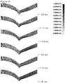
- Figure 10 shows the results of a simulation of the deformation upon impact of a blast of a Gull wing blast-protection element according to the invention (left side) and a V-shape blast-protection element (comparative, right side).
- This example is the same configuration and the result of the same calculation as for example 1.
- the simulations differed only in the shape of the impact section. The simulation was for 25 ms using finite element analysis.
- Figure 10 shows the results in transversal cross-sections through the centre of the deformed area as snapshots at 1.0, 1.5, 2.0, 5.0, 10.0 and 25.0 ms. Only half of the blast-shield is show. The two blast shields are simulated independently from each other.
- Figure 10 shows the half blast-protection element side by side for ease of comparison; they are not simulated as attached to each other.
- the grey scale of the shading indicates the fringe levels as sheet deformation in meters.
- the contour of the initial shape is shown as a guide to the eye.
- the actual contour in each snapshot shows the deformation.
- Figure 10 shows that the Gull-wing blast-protection element deformed less severe and had lower fringe levels than the V-shape blast-protection element.
Landscapes
- Engineering & Computer Science (AREA)
- General Engineering & Computer Science (AREA)
- Aiming, Guidance, Guns With A Light Source, Armor, Camouflage, And Targets (AREA)
Claims (15)
- Explosionsschutzelement (1) zum Schützen eines Fahrzeugs gegen eine Explosion, das Explosionsschutzelement (1) umfassend einen deformierbaren Aufprallabschnitt (2), wobei der Aufprallabschnitt eine explosionsgerichtete Oberfläche (5), mindestens einen Apexteil (3) und mindestens zwei explosionsführende Teile (4a, 4b) umfasst, wobei sich die explosionsführenden Teile (4a, 4b) an gegenüberliegenden Seiten des Apexteils (3) erstrecken, wobei das Apexteil einen hervorstehenden Apex (10) in der explosionsgerichteten Oberfläche umfasst und wobei die mindestens zwei explosionsführenden Teile jeweils einen konkaven Abschnitt der explosionsgerichteten Oberfläche (7a, 7b) umfassen,
wobei die explosionsführenden Teile insgesamt mindestens 75 % der Breite des Aufprallabschnitts überspannen und wobei mehr als 90 % der explosionsgerichteten Oberfläche von jedem der explosionsführenden Teile konkav ist, wobei die explosionsgerichtete Oberfläche des Aufprallabschnitts ein transversales Querschnittsprofil (11), umfassend den Apex (10) zwischen zwei Profilabschnitten, entsprechend zwei der explosionsführenden Teile (7a, 7b), definiert,
wobei die zwei konkaven Profilabschnitte einen Winkel (A) nach außen um den Apex herum von größer als 180° definieren,
dadurch gekennzeichnet, dass der Apex (10) in einem Mittelteil des transversalen Querschnittsprofils positioniert ist. - Explosionsschutzelement nach Anspruch 1, wobei jedes der explosionsführenden Teile sich unter externer Explosionsladung mindestens teilweise wie eine konkave Membran deformieren kann.
- Explosionsschutzelement nach einem der Ansprüche 1-2, wobei die explosionsgerichtete Oberfläche (5) des Aufprallabschnitts (2) ein transversales Querschnittsprofil (11) mit der allgemeinen Form einer nach innen gebogenen V-Form definiert.
- Explosionsschutzelement nach einem der Ansprüche 1-3, wobei die explosionsgerichtete Oberfläche (5) des Aufprallabschnitts (2) in einem Bereich neben einem Apex, wobei der vertikale Abstand zwischen der explosionsgerichteten Oberfläche und dem Apex weniger als 25 % der Höhe des Aufprallabschnitts ist, einen Einfallswinkel hat mit einer Explosionswelle, die sich in vertikaler Richtung von 45° oder größer ausbreitet.
- Explosionsschutzelement nach einem der Ansprüche 1-4, wobei die explosionsgerichtete Oberfläche (5) des Aufprallabschnitts (2) in einem Bereich neben einem Apex, wobei der vertikale Abstand zwischen der explosionsgerichteten Oberfläche und dem Apex weniger als 25 % der Höhe des Aufprallabschnitts ist, einen Einfallswinkel hat mit einer Explosionswelle, die sich in vertikaler Richtung von 60° oder größer ausbreitet.
- Explosionsschutzelement nach einem der Ansprüche 1-5, wobei die Höhe des Aufprallabschnitts (2) mehr als 30 % der Breite des Aufprallabschnitts ist.
- Explosionsschutzelement nach einem der Ansprüche 1-6, umfassend Mittel zum Befestigen (9) des Explosionsschutzelements (2) an einem Fahrzeug (18).
- Explosionsschutzelement nach einem der Ansprüche 1-7, wobei der Aufprallabschnitt eine der explosionsgerichteten Oberfläche gegenüberliegende Innenseite (6) umfasst, und wobei das Explosionsschutzelement eine oder mehrere Verstärkungsrippen (13), sich an der Innenseite des Aufprallabschnitts erstreckend, umfasst.
- Explosionsschutzelement nach Anspruch 8, wobei der Aufprallabschnitt mindestens teilweise aus einem faserverstärkten Verbundwerkstoff geformt ist.
- Explosionsschutzelement nach Anspruch 8 oder 9, wobei der Aufprallabschnitt mindestens teilweise aus einem Fasermetalllaminat geformt ist, umfassend ein Laminat aus mehreren dünnen Metallschichten, verbunden mit Schichten aus faserverstärktem Verbundmaterial.
- Explosionsschutzelement nach einem der Ansprüche 1-10, wobei der Apex (10) in eine explosionsgerichtete Richtung zeigt.
- Explosionsschutzelement nach einem der Ansprüche 1-11, wobei der Aufprallabschnitt aus einem Verbundmaterial geformt ist und/oder wobei der Aufprallabschnitt aus einem Material, umfassend ein Metall oder eine Legierung, geformt ist.
- Explosionsschutzelement nach einem der Ansprüche 1-12, wobei der Aufprallabschnitt aus einem Fasermetalllaminat geformt ist, umfassend ein Laminat aus mehreren dünnen Metallschichten, verbunden mit Schichten aus faserverstärktem Verbundmaterial.
- Landfahrzeug (18), umfassend ein Explosionsschutzelement (1) nach einem der Ansprüche 1-13.
- Verfahren zur Herstellung eines Landfahrzeugs nach Anspruch 14, umfassend Befestigen eines Explosionsschutzelements nach einem der Ansprüche 1-13 an einem Fahrzeug.
Applications Claiming Priority (2)
| Application Number | Priority Date | Filing Date | Title |
|---|---|---|---|
| NL2011848 | 2013-11-27 | ||
| PCT/EP2014/075865 WO2015078996A1 (en) | 2013-11-27 | 2014-11-27 | Blast-protection element |
Publications (2)
| Publication Number | Publication Date |
|---|---|
| EP3074714A1 EP3074714A1 (de) | 2016-10-05 |
| EP3074714B1 true EP3074714B1 (de) | 2018-05-30 |
Family
ID=50555172
Family Applications (1)
| Application Number | Title | Priority Date | Filing Date |
|---|---|---|---|
| EP14805262.4A Active EP3074714B1 (de) | 2013-11-27 | 2014-11-27 | Explosionsschutzelement |
Country Status (3)
| Country | Link |
|---|---|
| US (1) | US10323909B2 (de) |
| EP (1) | EP3074714B1 (de) |
| WO (1) | WO2015078996A1 (de) |
Families Citing this family (8)
| Publication number | Priority date | Publication date | Assignee | Title |
|---|---|---|---|---|
| CN106091823A (zh) * | 2016-08-11 | 2016-11-09 | 潘远蕻 | 轻型车辆用防弹装甲 |
| US10942010B1 (en) * | 2017-07-27 | 2021-03-09 | Hrl Laboratories, Llc | Architected armor |
| US20190310055A1 (en) * | 2018-04-09 | 2019-10-10 | Pratt & Miller Engineering and Fabrication, Inc. | Blast deflector |
| WO2021188207A2 (en) | 2020-01-29 | 2021-09-23 | Am General Llc | Armored cab for blast protection |
| DE102020107664A1 (de) | 2020-03-19 | 2021-09-23 | Rheinmetall MAN Military Vehicles Österreich GesmbH | Fahrerhaus und Nutzfahrzeug |
| US11453444B2 (en) | 2020-12-03 | 2022-09-27 | RV-De-Fender, LLC | Vehicle protection system to secure a protective covering to an axle of a vehicle |
| US11801904B2 (en) | 2021-11-16 | 2023-10-31 | Textron Systems Corporation | Techniques involving a modular vehicle belly armor kit |
| US12448053B2 (en) | 2023-02-10 | 2025-10-21 | RV-De-Fender, LLC | Mechanism for securing a vehicle protection system and a backing plate of a brake assembly to an axle of a vehicle |
Family Cites Families (38)
| Publication number | Priority date | Publication date | Assignee | Title |
|---|---|---|---|---|
| US1149127A (en) * | 1915-03-11 | 1915-08-03 | George Giem | Armored vehicle. |
| US3765299A (en) * | 1968-09-06 | 1973-10-16 | Us Army | Universal applique armor |
| US4316286A (en) * | 1980-03-07 | 1982-02-23 | Klein John M | Bulletproof protective plate assembly |
| US5533781A (en) * | 1994-06-20 | 1996-07-09 | O'gara-Hess & Eisenhardt Armoring Co., Inc. | Armoring assembly |
| DE10134394B4 (de) * | 2001-07-14 | 2004-02-12 | Rheinmetall Landsysteme Gmbh | Minenschutzboden für ein Panzerfahrzeug |
| DE102004026237A1 (de) * | 2004-02-11 | 2005-11-10 | Rheinmetall Landsysteme Gmbh | Fahrzeug mit Schutz gegen die Wirkung einer Landmine |
| AT413445B (de) * | 2004-02-18 | 2006-02-15 | Steyr Daimler Puch Ag | Minengeschützte fahrzeugwannenbodenstruktur |
| KR100636827B1 (ko) * | 2004-10-18 | 2006-10-20 | 국방과학연구소 | 운동량 전달형 반응 장갑 |
| US20100000399A1 (en) * | 2005-12-17 | 2010-01-07 | Ian Barnes | Barrier |
| WO2007076443A2 (en) * | 2005-12-21 | 2007-07-05 | Colt Rapid Mat, Llc | Rapidly installable energy barrier system |
| US20070186762A1 (en) * | 2005-12-22 | 2007-08-16 | Blackwater Lodge And Training Center Llc | Armored vehicle with blast deflecting hull |
| FR2897677B1 (fr) * | 2006-02-17 | 2010-05-28 | Giat Ind Sa | Dispositif de protection d'un plancher de vehicule |
| US7631589B2 (en) * | 2006-03-09 | 2009-12-15 | Lockheed Martin Corporation | Apparatus for inhibiting effects of an explosive blast |
| US7357062B2 (en) * | 2006-04-11 | 2008-04-15 | Force Protection Industries, Inc. | Mine resistant armored vehicle |
| WO2008127272A1 (en) | 2006-09-12 | 2008-10-23 | Protected Vehicles, Inc. | Systems and methods for enhancing the protection provided by armored vehicles |
| US7997182B1 (en) * | 2007-08-16 | 2011-08-16 | Timothy J. Cox | Protective hull for vehicles |
| US8365649B1 (en) * | 2008-02-13 | 2013-02-05 | Andrews Mark D | Multi-layered composite belly plate and method of making and using |
| FR2932557B1 (fr) * | 2008-06-13 | 2016-10-21 | Nexter Systems | Cabine blindee pour vehicule. |
| IL196456A0 (en) * | 2009-01-12 | 2009-12-24 | Shlomo Birger | Uderbelly of armord vehicle |
| US8033208B2 (en) * | 2009-04-10 | 2011-10-11 | Force Protection Technologies, Inc. | Mine resistant armored vehicle |
| US8146478B2 (en) * | 2009-04-10 | 2012-04-03 | Force Protection Technologies, Inc. | Mine resistant armored vehicle |
| US8646373B1 (en) * | 2009-05-04 | 2014-02-11 | Nova Research, Inc. | Blast wave effects reduction system |
| US8667880B1 (en) * | 2009-05-12 | 2014-03-11 | Granite Tactical Vehicles Inc. | Cabin for a Humvee vehicle |
| IL202275A0 (en) * | 2009-11-23 | 2010-11-30 | Plasan Sasa Ltd | A system for providing protection against an explosive threat |
| US8499677B2 (en) * | 2009-11-30 | 2013-08-06 | General Dynamics Land Systems—Canada Corporation | W-shaped hull |
| GB2480081B (en) * | 2010-05-05 | 2014-10-29 | Np Aerospace Ltd | Vehicle |
| US8146477B2 (en) * | 2010-05-14 | 2012-04-03 | Force Protection Technologies, Inc. | System for protecting a vehicle from a mine |
| US8413567B2 (en) * | 2010-06-23 | 2013-04-09 | International Truck Intellectual Property Company, Llc | Vehicle armor |
| IL207241A0 (en) * | 2010-07-26 | 2011-01-31 | Plasan Sasa Ltd | Belly armor |
| CA2748968A1 (en) * | 2010-08-09 | 2012-02-09 | Plasan Sasa Ltd. | Reinforcement system for a vehicle |
| US8752470B2 (en) * | 2011-01-31 | 2014-06-17 | Ideal Innovations Incorporated | Reduced size, symmetrical and asymmetrical crew compartment vehicle construction |
| US8424443B2 (en) * | 2011-01-31 | 2013-04-23 | The United States Of America As Represented By The Secretary Of The Army | Vented armor V structure |
| US8640594B2 (en) * | 2011-02-01 | 2014-02-04 | Corvid Technologies, Inc. | Blast deflecting shield for ground vehicles and shielded ground vehicles and methods including same |
| US20130036899A1 (en) * | 2011-06-17 | 2013-02-14 | Honeywell International Inc. | Blast mitigation system for military vehicles |
| US8413568B2 (en) * | 2011-07-15 | 2013-04-09 | Patrick Andrew Kosheleff | Mine protection for vehicle |
| US8955859B1 (en) * | 2011-09-27 | 2015-02-17 | Oshkosh Corporation | Isolated cab mounting system for an armored vehicle |
| US9097492B2 (en) * | 2012-05-31 | 2015-08-04 | Foster-Miller, Inc. | Blast/impact mitigation shield |
| US8770086B2 (en) * | 2012-08-31 | 2014-07-08 | International Truck Intellectual Property Company, Llc | Blast protection attachment |
-
2014
- 2014-11-27 US US15/039,049 patent/US10323909B2/en active Active
- 2014-11-27 EP EP14805262.4A patent/EP3074714B1/de active Active
- 2014-11-27 WO PCT/EP2014/075865 patent/WO2015078996A1/en not_active Ceased
Non-Patent Citations (1)
| Title |
|---|
| None * |
Also Published As
| Publication number | Publication date |
|---|---|
| WO2015078996A1 (en) | 2015-06-04 |
| EP3074714A1 (de) | 2016-10-05 |
| US10323909B2 (en) | 2019-06-18 |
| US20170176149A1 (en) | 2017-06-22 |
Similar Documents
| Publication | Publication Date | Title |
|---|---|---|
| EP3074714B1 (de) | Explosionsschutzelement | |
| US8640594B2 (en) | Blast deflecting shield for ground vehicles and shielded ground vehicles and methods including same | |
| US8833230B2 (en) | W-shaped hull | |
| CN106945728B (zh) | 局部能量吸收器 | |
| US8387511B2 (en) | Armored cab for vehicles | |
| US7685924B2 (en) | Protection device for the floor of a land vehicle | |
| EP2633259B1 (de) | Leichtes explosionsbeständiges gepanzertes fahrerhaus für fahrzeuge | |
| US11279408B2 (en) | Hollow member | |
| WO2010129109A1 (en) | Blast wave effects reduction system | |
| WO2013165522A2 (en) | Blast-resistant vehicle hull | |
| KR20200037390A (ko) | 중공 부재 | |
| EP3271237B1 (de) | Schweller für fahrzeuge und fahrzeug mit solchen schwellern | |
| WO2019035185A1 (ja) | バンパービーム及び車両 | |
| US20070029443A1 (en) | Cover for an aircraft structure | |
| US8844970B2 (en) | Armored vehicle protected from explosive devices | |
| US20180058820A1 (en) | Multiple layer hull | |
| CN104973139A (zh) | 车辆用发动机罩 | |
| CA2786168C (en) | W-shaped hull | |
| KR20200105709A (ko) | 프런트 필러 아우터 | |
| DK3077761T3 (en) | Armored vehicle connected to a chassis | |
| US20150251622A1 (en) | Motor vehicle rollover protection device and method | |
| US8371636B1 (en) | Shield | |
| US20250108864A1 (en) | Inner panel of automobile hood, automobile hood, and method for producing automobile hood | |
| US20220009561A1 (en) | Resin panel spacer block for energy absorption, load support, and gap prevention | |
| AU2009200694A1 (en) | Blast-protected structures for vehicles |
Legal Events
| Date | Code | Title | Description |
|---|---|---|---|
| PUAI | Public reference made under article 153(3) epc to a published international application that has entered the european phase |
Free format text: ORIGINAL CODE: 0009012 |
|
| 17P | Request for examination filed |
Effective date: 20160616 |
|
| AK | Designated contracting states |
Kind code of ref document: A1 Designated state(s): AL AT BE BG CH CY CZ DE DK EE ES FI FR GB GR HR HU IE IS IT LI LT LU LV MC MK MT NL NO PL PT RO RS SE SI SK SM TR |
|
| AX | Request for extension of the european patent |
Extension state: BA ME |
|
| DAX | Request for extension of the european patent (deleted) | ||
| GRAP | Despatch of communication of intention to grant a patent |
Free format text: ORIGINAL CODE: EPIDOSNIGR1 |
|
| INTG | Intention to grant announced |
Effective date: 20171222 |
|
| RIN1 | Information on inventor provided before grant (corrected) |
Inventor name: ROEBROEKS, GEERT H. J. J. Inventor name: CARTON, ERIK PETER |
|
| GRAS | Grant fee paid |
Free format text: ORIGINAL CODE: EPIDOSNIGR3 |
|
| GRAA | (expected) grant |
Free format text: ORIGINAL CODE: 0009210 |
|
| AK | Designated contracting states |
Kind code of ref document: B1 Designated state(s): AL AT BE BG CH CY CZ DE DK EE ES FI FR GB GR HR HU IE IS IT LI LT LU LV MC MK MT NL NO PL PT RO RS SE SI SK SM TR |
|
| REG | Reference to a national code |
Ref country code: GB Ref legal event code: FG4D |
|
| REG | Reference to a national code |
Ref country code: CH Ref legal event code: EP |
|
| REG | Reference to a national code |
Ref country code: AT Ref legal event code: REF Ref document number: 1004060 Country of ref document: AT Kind code of ref document: T Effective date: 20180615 |
|
| REG | Reference to a national code |
Ref country code: IE Ref legal event code: FG4D |
|
| REG | Reference to a national code |
Ref country code: DE Ref legal event code: R096 Ref document number: 602014026393 Country of ref document: DE |
|
| REG | Reference to a national code |
Ref country code: NL Ref legal event code: FP |
|
| REG | Reference to a national code |
Ref country code: LT Ref legal event code: MG4D |
|
| PG25 | Lapsed in a contracting state [announced via postgrant information from national office to epo] |
Ref country code: LT Free format text: LAPSE BECAUSE OF FAILURE TO SUBMIT A TRANSLATION OF THE DESCRIPTION OR TO PAY THE FEE WITHIN THE PRESCRIBED TIME-LIMIT Effective date: 20180530 Ref country code: CY Free format text: LAPSE BECAUSE OF FAILURE TO SUBMIT A TRANSLATION OF THE DESCRIPTION OR TO PAY THE FEE WITHIN THE PRESCRIBED TIME-LIMIT Effective date: 20180530 Ref country code: BG Free format text: LAPSE BECAUSE OF FAILURE TO SUBMIT A TRANSLATION OF THE DESCRIPTION OR TO PAY THE FEE WITHIN THE PRESCRIBED TIME-LIMIT Effective date: 20180830 Ref country code: ES Free format text: LAPSE BECAUSE OF FAILURE TO SUBMIT A TRANSLATION OF THE DESCRIPTION OR TO PAY THE FEE WITHIN THE PRESCRIBED TIME-LIMIT Effective date: 20180530 Ref country code: FI Free format text: LAPSE BECAUSE OF FAILURE TO SUBMIT A TRANSLATION OF THE DESCRIPTION OR TO PAY THE FEE WITHIN THE PRESCRIBED TIME-LIMIT Effective date: 20180530 Ref country code: SE Free format text: LAPSE BECAUSE OF FAILURE TO SUBMIT A TRANSLATION OF THE DESCRIPTION OR TO PAY THE FEE WITHIN THE PRESCRIBED TIME-LIMIT Effective date: 20180530 Ref country code: NO Free format text: LAPSE BECAUSE OF FAILURE TO SUBMIT A TRANSLATION OF THE DESCRIPTION OR TO PAY THE FEE WITHIN THE PRESCRIBED TIME-LIMIT Effective date: 20180830 |
|
| PG25 | Lapsed in a contracting state [announced via postgrant information from national office to epo] |
Ref country code: LV Free format text: LAPSE BECAUSE OF FAILURE TO SUBMIT A TRANSLATION OF THE DESCRIPTION OR TO PAY THE FEE WITHIN THE PRESCRIBED TIME-LIMIT Effective date: 20180530 Ref country code: GR Free format text: LAPSE BECAUSE OF FAILURE TO SUBMIT A TRANSLATION OF THE DESCRIPTION OR TO PAY THE FEE WITHIN THE PRESCRIBED TIME-LIMIT Effective date: 20180831 Ref country code: HR Free format text: LAPSE BECAUSE OF FAILURE TO SUBMIT A TRANSLATION OF THE DESCRIPTION OR TO PAY THE FEE WITHIN THE PRESCRIBED TIME-LIMIT Effective date: 20180530 Ref country code: RS Free format text: LAPSE BECAUSE OF FAILURE TO SUBMIT A TRANSLATION OF THE DESCRIPTION OR TO PAY THE FEE WITHIN THE PRESCRIBED TIME-LIMIT Effective date: 20180530 |
|
| REG | Reference to a national code |
Ref country code: AT Ref legal event code: MK05 Ref document number: 1004060 Country of ref document: AT Kind code of ref document: T Effective date: 20180530 |
|
| PG25 | Lapsed in a contracting state [announced via postgrant information from national office to epo] |
Ref country code: PL Free format text: LAPSE BECAUSE OF FAILURE TO SUBMIT A TRANSLATION OF THE DESCRIPTION OR TO PAY THE FEE WITHIN THE PRESCRIBED TIME-LIMIT Effective date: 20180530 Ref country code: SK Free format text: LAPSE BECAUSE OF FAILURE TO SUBMIT A TRANSLATION OF THE DESCRIPTION OR TO PAY THE FEE WITHIN THE PRESCRIBED TIME-LIMIT Effective date: 20180530 Ref country code: CZ Free format text: LAPSE BECAUSE OF FAILURE TO SUBMIT A TRANSLATION OF THE DESCRIPTION OR TO PAY THE FEE WITHIN THE PRESCRIBED TIME-LIMIT Effective date: 20180530 Ref country code: RO Free format text: LAPSE BECAUSE OF FAILURE TO SUBMIT A TRANSLATION OF THE DESCRIPTION OR TO PAY THE FEE WITHIN THE PRESCRIBED TIME-LIMIT Effective date: 20180530 Ref country code: EE Free format text: LAPSE BECAUSE OF FAILURE TO SUBMIT A TRANSLATION OF THE DESCRIPTION OR TO PAY THE FEE WITHIN THE PRESCRIBED TIME-LIMIT Effective date: 20180530 Ref country code: DK Free format text: LAPSE BECAUSE OF FAILURE TO SUBMIT A TRANSLATION OF THE DESCRIPTION OR TO PAY THE FEE WITHIN THE PRESCRIBED TIME-LIMIT Effective date: 20180530 Ref country code: AT Free format text: LAPSE BECAUSE OF FAILURE TO SUBMIT A TRANSLATION OF THE DESCRIPTION OR TO PAY THE FEE WITHIN THE PRESCRIBED TIME-LIMIT Effective date: 20180530 |
|
| PG25 | Lapsed in a contracting state [announced via postgrant information from national office to epo] |
Ref country code: SM Free format text: LAPSE BECAUSE OF FAILURE TO SUBMIT A TRANSLATION OF THE DESCRIPTION OR TO PAY THE FEE WITHIN THE PRESCRIBED TIME-LIMIT Effective date: 20180530 |
|
| REG | Reference to a national code |
Ref country code: DE Ref legal event code: R097 Ref document number: 602014026393 Country of ref document: DE |
|
| PLBE | No opposition filed within time limit |
Free format text: ORIGINAL CODE: 0009261 |
|
| STAA | Information on the status of an ep patent application or granted ep patent |
Free format text: STATUS: NO OPPOSITION FILED WITHIN TIME LIMIT |
|
| 26N | No opposition filed |
Effective date: 20190301 |
|
| PG25 | Lapsed in a contracting state [announced via postgrant information from national office to epo] |
Ref country code: SI Free format text: LAPSE BECAUSE OF FAILURE TO SUBMIT A TRANSLATION OF THE DESCRIPTION OR TO PAY THE FEE WITHIN THE PRESCRIBED TIME-LIMIT Effective date: 20180530 |
|
| REG | Reference to a national code |
Ref country code: CH Ref legal event code: PL |
|
| PG25 | Lapsed in a contracting state [announced via postgrant information from national office to epo] |
Ref country code: MC Free format text: LAPSE BECAUSE OF FAILURE TO SUBMIT A TRANSLATION OF THE DESCRIPTION OR TO PAY THE FEE WITHIN THE PRESCRIBED TIME-LIMIT Effective date: 20180530 Ref country code: LU Free format text: LAPSE BECAUSE OF NON-PAYMENT OF DUE FEES Effective date: 20181127 |
|
| REG | Reference to a national code |
Ref country code: BE Ref legal event code: MM Effective date: 20181130 |
|
| REG | Reference to a national code |
Ref country code: IE Ref legal event code: MM4A |
|
| PG25 | Lapsed in a contracting state [announced via postgrant information from national office to epo] |
Ref country code: CH Free format text: LAPSE BECAUSE OF NON-PAYMENT OF DUE FEES Effective date: 20181130 Ref country code: LI Free format text: LAPSE BECAUSE OF NON-PAYMENT OF DUE FEES Effective date: 20181130 |
|
| PG25 | Lapsed in a contracting state [announced via postgrant information from national office to epo] |
Ref country code: IE Free format text: LAPSE BECAUSE OF NON-PAYMENT OF DUE FEES Effective date: 20181127 |
|
| PG25 | Lapsed in a contracting state [announced via postgrant information from national office to epo] |
Ref country code: AL Free format text: LAPSE BECAUSE OF FAILURE TO SUBMIT A TRANSLATION OF THE DESCRIPTION OR TO PAY THE FEE WITHIN THE PRESCRIBED TIME-LIMIT Effective date: 20180530 Ref country code: BE Free format text: LAPSE BECAUSE OF NON-PAYMENT OF DUE FEES Effective date: 20181130 |
|
| PG25 | Lapsed in a contracting state [announced via postgrant information from national office to epo] |
Ref country code: MT Free format text: LAPSE BECAUSE OF NON-PAYMENT OF DUE FEES Effective date: 20181127 |
|
| PG25 | Lapsed in a contracting state [announced via postgrant information from national office to epo] |
Ref country code: PT Free format text: LAPSE BECAUSE OF FAILURE TO SUBMIT A TRANSLATION OF THE DESCRIPTION OR TO PAY THE FEE WITHIN THE PRESCRIBED TIME-LIMIT Effective date: 20180530 |
|
| PG25 | Lapsed in a contracting state [announced via postgrant information from national office to epo] |
Ref country code: HU Free format text: LAPSE BECAUSE OF FAILURE TO SUBMIT A TRANSLATION OF THE DESCRIPTION OR TO PAY THE FEE WITHIN THE PRESCRIBED TIME-LIMIT; INVALID AB INITIO Effective date: 20141127 Ref country code: MK Free format text: LAPSE BECAUSE OF NON-PAYMENT OF DUE FEES Effective date: 20180530 |
|
| PG25 | Lapsed in a contracting state [announced via postgrant information from national office to epo] |
Ref country code: IS Free format text: LAPSE BECAUSE OF FAILURE TO SUBMIT A TRANSLATION OF THE DESCRIPTION OR TO PAY THE FEE WITHIN THE PRESCRIBED TIME-LIMIT Effective date: 20180930 |
|
| P01 | Opt-out of the competence of the unified patent court (upc) registered |
Effective date: 20230522 |
|
| PGFP | Annual fee paid to national office [announced via postgrant information from national office to epo] |
Ref country code: NL Payment date: 20251119 Year of fee payment: 12 |
|
| PGFP | Annual fee paid to national office [announced via postgrant information from national office to epo] |
Ref country code: DE Payment date: 20251119 Year of fee payment: 12 |
|
| PGFP | Annual fee paid to national office [announced via postgrant information from national office to epo] |
Ref country code: GB Payment date: 20251120 Year of fee payment: 12 |
|
| PGFP | Annual fee paid to national office [announced via postgrant information from national office to epo] |
Ref country code: IT Payment date: 20251125 Year of fee payment: 12 |
|
| PGFP | Annual fee paid to national office [announced via postgrant information from national office to epo] |
Ref country code: FR Payment date: 20251126 Year of fee payment: 12 |
|
| PGFP | Annual fee paid to national office [announced via postgrant information from national office to epo] |
Ref country code: TR Payment date: 20251119 Year of fee payment: 12 |