EP3075335A2 - Anordnung zur befestigung eines chirurgischen instruments an einem patientenknochen - Google Patents
Anordnung zur befestigung eines chirurgischen instruments an einem patientenknochen Download PDFInfo
- Publication number
- EP3075335A2 EP3075335A2 EP16160726.2A EP16160726A EP3075335A2 EP 3075335 A2 EP3075335 A2 EP 3075335A2 EP 16160726 A EP16160726 A EP 16160726A EP 3075335 A2 EP3075335 A2 EP 3075335A2
- Authority
- EP
- European Patent Office
- Prior art keywords
- elongated shaft
- sheath
- surgical instrument
- fixation pin
- distal end
- Prior art date
- Legal status (The legal status is an assumption and is not a legal conclusion. Google has not performed a legal analysis and makes no representation as to the accuracy of the status listed.)
- Withdrawn
Links
- 210000000988 bone and bone Anatomy 0.000 title claims abstract description 65
- 238000000034 method Methods 0.000 description 4
- 238000010276 construction Methods 0.000 description 3
- 210000003484 anatomy Anatomy 0.000 description 2
- 229910000639 Spring steel Inorganic materials 0.000 description 1
- 210000003423 ankle Anatomy 0.000 description 1
- 238000011882 arthroplasty Methods 0.000 description 1
- -1 for example Substances 0.000 description 1
- 239000007943 implant Substances 0.000 description 1
- 210000003127 knee Anatomy 0.000 description 1
- 239000007769 metal material Substances 0.000 description 1
- 238000003801 milling Methods 0.000 description 1
- 239000012858 resilient material Substances 0.000 description 1
- 238000004513 sizing Methods 0.000 description 1
- 229910001220 stainless steel Inorganic materials 0.000 description 1
- 239000010935 stainless steel Substances 0.000 description 1
- 238000001356 surgical procedure Methods 0.000 description 1
- 210000000707 wrist Anatomy 0.000 description 1
Images




Classifications
-
- A—HUMAN NECESSITIES
- A61—MEDICAL OR VETERINARY SCIENCE; HYGIENE
- A61B—DIAGNOSIS; SURGERY; IDENTIFICATION
- A61B17/00—Surgical instruments, devices or methods
- A61B17/56—Surgical instruments or methods for treatment of bones or joints; Devices specially adapted therefor
- A61B17/58—Surgical instruments or methods for treatment of bones or joints; Devices specially adapted therefor for osteosynthesis, e.g. bone plates, screws or setting implements
- A61B17/88—Osteosynthesis instruments; Methods or means for implanting or extracting internal or external fixation devices
- A61B17/8875—Screwdrivers, spanners or wrenches
- A61B17/8886—Screwdrivers, spanners or wrenches holding the screw head
- A61B17/8891—Screwdrivers, spanners or wrenches holding the screw head at its periphery
-
- A—HUMAN NECESSITIES
- A61—MEDICAL OR VETERINARY SCIENCE; HYGIENE
- A61B—DIAGNOSIS; SURGERY; IDENTIFICATION
- A61B17/00—Surgical instruments, devices or methods
- A61B17/16—Instruments for performing osteoclasis; Drills or chisels for bones; Trepans
- A61B17/17—Guides or aligning means for drills, mills, pins or wires
- A61B17/1739—Guides or aligning means for drills, mills, pins or wires specially adapted for particular parts of the body
-
- A—HUMAN NECESSITIES
- A61—MEDICAL OR VETERINARY SCIENCE; HYGIENE
- A61B—DIAGNOSIS; SURGERY; IDENTIFICATION
- A61B17/00—Surgical instruments, devices or methods
- A61B17/14—Surgical saws
-
- A—HUMAN NECESSITIES
- A61—MEDICAL OR VETERINARY SCIENCE; HYGIENE
- A61B—DIAGNOSIS; SURGERY; IDENTIFICATION
- A61B17/00—Surgical instruments, devices or methods
- A61B17/14—Surgical saws
- A61B17/15—Guides therefor
-
- A—HUMAN NECESSITIES
- A61—MEDICAL OR VETERINARY SCIENCE; HYGIENE
- A61B—DIAGNOSIS; SURGERY; IDENTIFICATION
- A61B17/00—Surgical instruments, devices or methods
- A61B17/16—Instruments for performing osteoclasis; Drills or chisels for bones; Trepans
- A61B17/1604—Chisels; Rongeurs; Punches; Stamps
-
- A—HUMAN NECESSITIES
- A61—MEDICAL OR VETERINARY SCIENCE; HYGIENE
- A61B—DIAGNOSIS; SURGERY; IDENTIFICATION
- A61B17/00—Surgical instruments, devices or methods
- A61B17/16—Instruments for performing osteoclasis; Drills or chisels for bones; Trepans
- A61B17/1657—Bone breaking devices
-
- A—HUMAN NECESSITIES
- A61—MEDICAL OR VETERINARY SCIENCE; HYGIENE
- A61B—DIAGNOSIS; SURGERY; IDENTIFICATION
- A61B17/00—Surgical instruments, devices or methods
- A61B17/16—Instruments for performing osteoclasis; Drills or chisels for bones; Trepans
- A61B17/1659—Surgical rasps, files, planes, or scrapers
-
- A—HUMAN NECESSITIES
- A61—MEDICAL OR VETERINARY SCIENCE; HYGIENE
- A61B—DIAGNOSIS; SURGERY; IDENTIFICATION
- A61B17/00—Surgical instruments, devices or methods
- A61B17/16—Instruments for performing osteoclasis; Drills or chisels for bones; Trepans
- A61B17/1662—Instruments for performing osteoclasis; Drills or chisels for bones; Trepans for particular parts of the body
-
- A—HUMAN NECESSITIES
- A61—MEDICAL OR VETERINARY SCIENCE; HYGIENE
- A61B—DIAGNOSIS; SURGERY; IDENTIFICATION
- A61B17/00—Surgical instruments, devices or methods
- A61B17/56—Surgical instruments or methods for treatment of bones or joints; Devices specially adapted therefor
- A61B17/58—Surgical instruments or methods for treatment of bones or joints; Devices specially adapted therefor for osteosynthesis, e.g. bone plates, screws or setting implements
- A61B17/68—Internal fixation devices, including fasteners and spinal fixators, even if a part thereof projects from the skin
- A61B17/84—Fasteners therefor or fasteners being internal fixation devices
- A61B17/86—Pins or screws or threaded wires; nuts therefor
- A61B17/8605—Heads, i.e. proximal ends projecting from bone
- A61B17/861—Heads, i.e. proximal ends projecting from bone specially shaped for gripping driver
- A61B17/862—Heads, i.e. proximal ends projecting from bone specially shaped for gripping driver at the periphery of the screw head
-
- A—HUMAN NECESSITIES
- A61—MEDICAL OR VETERINARY SCIENCE; HYGIENE
- A61B—DIAGNOSIS; SURGERY; IDENTIFICATION
- A61B17/00—Surgical instruments, devices or methods
- A61B17/56—Surgical instruments or methods for treatment of bones or joints; Devices specially adapted therefor
- A61B17/58—Surgical instruments or methods for treatment of bones or joints; Devices specially adapted therefor for osteosynthesis, e.g. bone plates, screws or setting implements
- A61B17/88—Osteosynthesis instruments; Methods or means for implanting or extracting internal or external fixation devices
- A61B17/8875—Screwdrivers, spanners or wrenches
- A61B17/8877—Screwdrivers, spanners or wrenches characterised by the cross-section of the driver bit
- A61B17/8883—Screwdrivers, spanners or wrenches characterised by the cross-section of the driver bit the driver bit acting on the periphery of the screw head
-
- A—HUMAN NECESSITIES
- A61—MEDICAL OR VETERINARY SCIENCE; HYGIENE
- A61B—DIAGNOSIS; SURGERY; IDENTIFICATION
- A61B17/00—Surgical instruments, devices or methods
- A61B17/14—Surgical saws
- A61B17/15—Guides therefor
- A61B17/154—Guides therefor for preparing bone for knee prosthesis
- A61B17/155—Cutting femur
-
- A—HUMAN NECESSITIES
- A61—MEDICAL OR VETERINARY SCIENCE; HYGIENE
- A61B—DIAGNOSIS; SURGERY; IDENTIFICATION
- A61B17/00—Surgical instruments, devices or methods
- A61B17/56—Surgical instruments or methods for treatment of bones or joints; Devices specially adapted therefor
- A61B17/58—Surgical instruments or methods for treatment of bones or joints; Devices specially adapted therefor for osteosynthesis, e.g. bone plates, screws or setting implements
- A61B17/68—Internal fixation devices, including fasteners and spinal fixators, even if a part thereof projects from the skin
- A61B17/84—Fasteners therefor or fasteners being internal fixation devices
- A61B17/86—Pins or screws or threaded wires; nuts therefor
- A61B17/8645—Headless screws, e.g. ligament interference screws
-
- A—HUMAN NECESSITIES
- A61—MEDICAL OR VETERINARY SCIENCE; HYGIENE
- A61B—DIAGNOSIS; SURGERY; IDENTIFICATION
- A61B17/00—Surgical instruments, devices or methods
- A61B17/56—Surgical instruments or methods for treatment of bones or joints; Devices specially adapted therefor
- A61B2017/564—Methods for bone or joint treatment
-
- A—HUMAN NECESSITIES
- A61—MEDICAL OR VETERINARY SCIENCE; HYGIENE
- A61B—DIAGNOSIS; SURGERY; IDENTIFICATION
- A61B90/00—Instruments, implements or accessories specially adapted for surgery or diagnosis and not covered by any of the groups A61B1/00 - A61B50/00, e.g. for luxation treatment or for protecting wound edges
- A61B90/03—Automatic limiting or abutting means, e.g. for safety
- A61B2090/033—Abutting means, stops, e.g. abutting on tissue or skin
Definitions
- the present invention relates generally to orthopaedic surgical instruments and, more particularly, to surgical instruments used to resect a patient's bone.
- Joint arthroplasty is a well-known surgical procedure by which a diseased and/or damaged natural joint is replaced by a prosthetic joint.
- Typical artificial joints include knee prostheses, hip prostheses, shoulder prostheses, ankle prostheses, and wrist prostheses, among others.
- orthopaedic surgeons use a variety of orthopaedic surgical instruments such as, for example, saws, drills, reamers, rasps, broaches, cutting blocks, drill guides, milling guides, and other surgical instruments.
- the invention provides a surgical instrument system which comprises a bone fixation pin including a head and a shaft extending from the head to a distal end having a plurality of threads defined therein, and a surgical instrument configured for use with the bone fixation pin.
- the surgical instrument comprises an elongated shaft defining a longitudinal axis extending through its proximal end and its distal end, a socket defined in the distal end of the elongated shaft that is sized to receive the head of the bone fixation pin, a shank extending outwardly from the proximal end of the elongated shaft along the longitudinal axis that is configured to engage a surgical drill, a sheath extending over the distal end of the elongated shaft, and a locking mechanism coupled to the elongated shaft.
- the locking mechanism is operable to permit selectively movement of the elongated shaft along the longitudinal axis relative to the sheath between a position in which over-turning or applying too much torque to the bone fixation pin is prevented and another position in which full torque may be applied to the bone fixation pin for final tightening or removal of the pin from the bone. In that way, the torque applied to the bone fixation pin may be controlled.
- the locking mechanism may include a locking tab that is moveable between a locked position in which the locking tab is positioned in an opening of the sheath to prevent movement of the elongated shaft and an unlocked position in which the locking tab is spaced apart from the opening to permit movement of the elongated shaft.
- the locking mechanism may include a body that is positioned in a slot defined in the elongated shaft, and the locking tab may extend outwardly from the body.
- the body may include a biassing element that biasses the locking tab in the locked position.
- the slot defined in the elongated shaft may extend longitudinally through the elongated shaft.
- the body may include a first end engaged with an inner surface of the sheath.
- a second end of the body may be engaged with a distal-facing surface of the elongated shaft.
- the second end of the body may be disengaged from the distal-facing surface of the elongated shaft.
- the first end of the body may be received in a groove defined in the inner surface of the sheath.
- the sheath may include a distal opening defined in its distal end and a central passageway that extends inwardly from the distal opening.
- the elongated shaft may be positioned in the central passageway of the sheath. When the elongated shaft is moved in a first direction relative to the sheath, the distal end of the elongated shaft may be moved along the central passageway toward the distal end of the sheath.
- the head of the bone fixation pin may extend from a proximal end of the bone fixation pin to a distal edge.
- the threads of the shaft may extend from the distal end to a proximal edge, and a first distance may be defined between the distal edge of the head and the proximal edge of the threads.
- a second distance may be defined between the distal opening of the sheath and the distal end of the elongated shaft. The second distance may be greater than the first distance such that a number of the threads of the bone fixation pin are positioned in the central passageway of the sheath when the head of the bone fixation pin is fully seated in the socket of the elongated shaft.
- the elongated shaft may be moveable to a second position in which a third distance is defined between the opening of the sheath and the distal end of the elongated shaft.
- the third distance may be less than the first distance.
- the locking mechanism may be biassed in a locked position in which the elongated shaft is prevented from moving relative to the sheath when the elongated shaft is in the first position. Additionally, the locking mechanism may be in an unlocked position in which the elongated shaft is permitted to move relative to the sheath when the elongated shaft is the second position.
- the elongated shaft may include a pair of tabs extending outwardly from its proximal end and the sheath includes a pair of guide slots that receive the pair of tabs.
- the guide slots and the tabs may cooperate to prevent rotational movement about the longitudinal axis.
- the socket and the head of the bone fixation pin may have corresponding triangular cross sections.
- a method of attaching a surgical instrument to a patient's bone can comprise positioning the surgical instrument in a desired location relative to the patient's bone, inserting a head of a bone fixation pin through a distal opening of a fixation pin driver into a socket defined in an elongated shaft of the fixation pin driver, positioning a threaded distal end of the bone fixation pin in a guide hole defined in the surgical instrument, rotating the fixation pin driver to thread the bone fixation pin into the patient's bone, engaging a distal end of the fixation pin driver with an outer surface of the surgical instrument, operating a locking mechanism of the fixation pin driver to release the elongated shaft of the fixation pin driver for movement relative to an outer sheath of the fixation pin driver that includes the distal end of the driver, and rotating the fixation pin driver and advancing the socket of the fixation pin driver toward the distal opening of the fixation pin driver to further thread the bone fixation pin into the patient's bone.
- the method may further comprise securing a proximal end of the elongated shaft to a surgical drill.
- the surgical instrument may be a cutting guide block.
- the method may further comprise engaging an annular flange of the bone fixation pin with the outer surface of the surgical instrument after advancing the socket of the fixation pin driver toward the distal opening of the fixation pin driver.
- the method may further comprise moving the socket of the fixation pin driver away the distal opening of a fixation pin driver until a biassing element causes the locking mechanism to engage the outer sheath and prevent movement of the elongated shaft.
- the invention also provides a surgical instrument system which comprises a bone fixation pin including a head extending from a proximal end of the bone fixation pin to a distal edge, and a shaft extending from the head to a distal end having a plurality of threads defined therein that extend from the distal end to a proximal edge.
- the system also includes a surgical instrument configured for use with the bone fixation pin.
- the surgical instrument comprises a socket sized to receive the head of the bone fixation pin and a sheath extending over the socket to a distal end. A first distance is defined between the distal edge of the head and the proximal edge of the threads of the bone fixation pin, and the socket is moveable between a plurality of positions relative to the sheath.
- the plurality of positions includes a first position in which a second distance is defined between the distal end of the sheath and the socket such that a number of the threads of the bone fixation pin are positioned in the sheath when the head of the bone fixation pin is fully seated in the socket.
- the socket may be moveable to a second position in which a third distance is defined between the distal end of the sheath and the socket. The third distance may be less than the first distance.
- anatomical references such as anterior, posterior, medial, lateral, superior and inferior, may be used throughout this document to refer to the orthopaedic implants or prostheses and surgical instruments described herein as well as to refer to the patient's natural anatomy. Such terms have well-understood meanings in both the study of anatomy and the field of orthopaedics. Use of such anatomical reference terms in this document is intended to be consistent with their well-understood meanings unless noted otherwise.
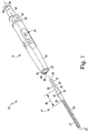
- FIG. 1 shows a surgical instrument system 10 for attaching a surgical instrument to a patient's bone, which includes a bone fixation pin 12 and a fixation pin driver 14 configured to be attached to the head 16 of the fixation pin 12.
- the driver 14 is operable to control the torque applied to the fixation pin 12.
- the fixation pin 12 includes an elongated shaft 18 that extends distally from the head 16 to a distal tip 20 of the pin 12.
- the pin 12 is formed as a single, monolithic component from a metallic material such as, for example, stainless steel.
- the head 16 and shaft 18, for example might be formed as separate components.
- a plurality of threads 22 are defined in the elongated shaft 18 and extend from the distal tip 20 to a proximal edge 24. The threads 22 are configured to grip the patient's bone to hold the pin 12 (hence the surgical instrument) in position on the bone.
- the head 16 of the fixation pin 12 is positioned at a proximal end 26 of the pin 12.
- the head 16 includes a number of substantially planar surfaces 28 that extend distally from the proximal end 26 to a distal edge 30.
- the surfaces 28 define a generally triangular-shape. In other constructions, the surfaces 28 may define, for example, a generally square shape.
- the elongated shaft 18 includes a substantially smooth surface 32 that connects the proximal edge 24 of the threads 22 to the distal edge 30 of the head 16.
- the fixation pin 12 also includes an annular flange 34 that extends outwardly from the surface 32. As shown in FIG. 1 , a distance 36 is defined between the distal edge 30 and the proximal edge 24.
- the driver 14 includes a sheath 40 that extends over an elongated shaft 42.
- the shaft 42 is moveable relative to the sheath 40, but the driver 14 includes a locking mechanism 44 operable to fix the sheath 40 and the shaft 42 in position relative to one another.
- the shaft 42 has a drive shank 46 formed at its proximal end 48.
- the shank 46 is configured to engage a surgical drill or other rotary tool operable to rotate the driver 14 about its longitudinal axis 50. As shown in FIG. 1 , the longitudinal axis 50 extends through the proximal end 48 of the shaft 42 and the distal end 52 of the sheath 40.
- An opening 54 is defined in the distal end 52 of the sheath 40, and a cylindrical inner wall 56 extends inwardly from the opening 54.
- the inner wall 56 defines a central passageway 58 that extends through the distal end 52 and opposite proximal end 60 of the sheath 40.
- the elongated shaft 42 extends outwardly from the proximal end 60 of the sheath 40 to its proximal end 48.
- the distal end 62 of the elongated shaft 42 is positioned in the central passageway 58.
- a socket 64 sized to receive the head 16 of the fixation pin 12 is defined in the distal end 62 of the shaft 42.
- the socket 64 has a number of substantially planar surfaces 66 that extend inwardly from an annular bevelled surface 68.
- the surfaces 66 correspond in shape and arrangement to the surfaces 28 of the head 16 such that the head 16 may be snugly in the socket 64.
- the socket 64 is sized so that the head 16 fully seats in the socket 64, with the annular flange 34 of the pin 12 engaged with the distal end 62 of the elongated shaft 42.
- the shaft 42 is moveable relative to the sheath 40. As shown in FIGS. 3 and 4 , the shaft 42 is moveable between a controlled-torque position 70 (see FIG. 3 ) and a full torque position 72 (see FIG. 4 ). In the controlled-torque position 70, the distal flange 74 of the shank 46 is spaced apart from the proximal end 60 of the sheath 40, and the socket 64 is spaced inwardly from the distal opening 54 of the sheath 40. In the full torque position 72, the distal flange 74 of the shank 46 is engaged with the proximal end 60 of the sheath 40. Additionally, the socket 64 is positioned adjacent the distal opening 54 of the sheath 40.
- the locking mechanism 44 includes a locking tab 76 that is configured to be received in a slot 78 defined in the sheath 40 when the shaft 42 is in a controlled-torque position 70.
- the engagement between the locking tab 76 and the sheath 40 fixes the sheath 40 and the shaft 42 in position relative to one another, as described below.
- FIG. 5 shows the sheath 40, the shaft 42, and the locking mechanism 44 in greater detail.
- the sheath 40 is an assembly of two components 80, 82.
- the sheath 40 may be formed as a single monolithic component in other constructions.
- the component 80 is positioned distally and defines the distal end 52 of the sheath 40.
- the other component 82 includes the proximal end 60 of the sheath 40.
- a pair of flanges 84 extend distally from the component 82 and are configured to engage a corresponding pair of slots 86 defined in the component 80 to secure the components 80, 82 and assemble the sheath 40.
- the proximal component 82 includes a substantially planar surface 88, and a generally rectangular opening 90 is defined in the surface 88.
- a number of inner walls 92 extend inwardly from the opening 90 to define the locking slot 78 described above.
- the locking slot 78 opens into the central passageway 58, which extends through both the components 80, 82 of the sheath 40.
- the elongated shaft 42 has a distal end 62 that is positioned in the central passageway 58 of the sheath 40.
- a substantially cylindrical surface 100 extends from the distal end 62 to the drive shank 46 formed at the proximal end 48 of the shaft 42.
- a pair of tabs 102 extends outwardly from the surface 100 near the drive shank 46.
- Each tab 102 is received in a guide slot or groove 104 defined in the inner wall 56 of the proximal component 82.
- the tabs 102 and grooves 104 cooperate to guide the relative movement of the shaft 42 and sheath 40 and prevent relative rotation between the shaft 42 and the sheath 40.
- the shaft 42 has a longitudinal opening 110 defined in the cylindrical surface 100.
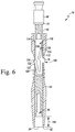
- a number of inner walls 112 extend inwardly from the opening 110 to another longitudinal opening 114 defined in the opposite side of the surface 100 to define a slot 116 extending through the shaft 42, as shown in FIG. 6 .
- the walls 112 further cooperate to define an inner chamber 118 positioned proximal of the slot 116.
- the slot 116 and inner chamber 118 are sized to receive the lever 120 of the locking mechanism 44.
- the locking mechanism 44 has a lever 120 and the locking tab 76 described above.
- the lever 120 extends from an end 122 that engages the sheath 40 to another lever end 124 that engages the elongated shaft 42.
- the lever 120 includes an arm 126 that extends from the lever end 122 and is joined at its opposite end to a body 128.
- the body 128 connects the arm 126 to another arm 130 that extends from the lever end 124.
- the locking tab 76 extends outwardly from the connecting body 128.
- the lever 120 and locking tab 76 are formed as a single monolithic component from a resilient material such as, for example, spring steel.
- the arm 126 has a lip 132 formed at the lever end 122 that is received in a groove 134 defined in the inner wall 56 of the proximal component 82 of the sheath 40.
- the arm 130 has a substantially planar or flat surface 136 at the opposite lever end 124, which is configured to engage a distal-facing surface 138 of the elongated shaft 42.
- the elongated shaft 42 of the fixation pin driver 14 is positioned in the controlled-torque position 70 shown in FIGS. 4 and 6 .
- the surface 136 of the locking mechanism lever 120 is engaged with the distal-facing surface 138 of the elongated shaft 42 and the locking tab 76 is positioned in the slot 78 defined in the sheath 40.
- the distal end 52 of the elongated shaft 42 (and hence the socket 64) is spaced apart from the distal opening 54 of the sheath 40 such that a distance 140 is defined between the opening 54 and the distal end 52 and socket 64 of the elongated shaft 42.
- a user may load a bone fixation pin 12 into the driver 14 by aligning the head 16 of the pin 12 with the distal opening 54 of the sheath 40. The user may then advance the head 16 of the pin 12 into the distal opening 54, along the central passageway 58, and into the socket 64 of the elongated shaft 42. As described above, the annular flange 34 of the pin 12 engages the distal end 62 of the elongated shaft 42 when the head 16 is fully seated in the socket 64.
- the user may align the distal tip 20 of the pin 12 with a guide pin hole 150 of a surgical instrument such as, for example, femoral cutting block 152, to be secured to the patient's bone 154.
- a surgical instrument such as, for example, femoral cutting block 152
- the surgical instrument may be a tibial cutting block, a sizing block, gauge, or other surgical instrument.
- the user may then advance the distal tip 20 into the hole 150 and into contact with the patient's bone 154.
- a surgical drill or other rotary power tool may be attached to the drive shank 46 to rotate the driver 14 (and hence the fixation pin 12) to screw the pin 12 into the patient's bone 154.
- the driver 14 is rotated about its axis 50
- the pin 12 advances into the patient's bone 154, and the distal end 62 of the sheath 40 is advanced into contact with the cutting block 152, as shown in FIG. 9 .
- the distal end 62 of the sheath 40 contacts the cutting block 152, further movement of the driver 14 toward the patient's bone 154 is prevented.
- continued rotation of the driver 14 causes the pin 12 to continue to advance into the patient's bone 154.
- the head 16 of the pin 12 is advanced distally, away from the socket 64.
- the head 16 is advanced out of engagement with the socket 64.
- the sheath 40 is sized so that the head 16 is advanced out of engagement with the socket 64 to prevent the user from applying too great a torque to the pin 12.
- the user may depress the locking tab 76 by applying a force in the direction indicated by arrow 156 in FIG. 6 .
- the locking tab 76 is disengaged from the slot 78, the user may advance the elongated shaft 42 along the longitudinal axis to the full torque position 72 shown in FIG. 7 .
- the lever 120 urges the tab 76 back into the slot 78, as shown in FIG. 7 .
- the distal end 52 of the elongated shaft 42 (and hence the socket 64) is positioned adjacent to the distal opening 54 of the sheath 40 such that a distance 160 is defined between the opening 54 and the distal end 52 and socket 64 of the elongated shaft 42.
- the distance 160 is less than the distance 36 defined between the distal edge 30 of the fixation pin head 16 and the proximal edge 24 of the threads 22 such that the user may apply the full torque of the surgical drill to the fixation pin 12. In that way, additional torque may be applied to the pin 12 to further tighten the pin or remove the pin 12 from the bone.
- the user may pull on the shank 46 as indicated by arrow 162.
- the arm 130 of the lever 120 slides along the inner wall 112 of the elongated shaft 42 until it reengages the distal-facing surface 138 in the controlled-torque position 70.
Landscapes
- Health & Medical Sciences (AREA)
- Surgery (AREA)
- Life Sciences & Earth Sciences (AREA)
- Orthopedic Medicine & Surgery (AREA)
- Biomedical Technology (AREA)
- Public Health (AREA)
- Veterinary Medicine (AREA)
- Engineering & Computer Science (AREA)
- Nuclear Medicine, Radiotherapy & Molecular Imaging (AREA)
- Heart & Thoracic Surgery (AREA)
- Medical Informatics (AREA)
- Molecular Biology (AREA)
- Animal Behavior & Ethology (AREA)
- General Health & Medical Sciences (AREA)
- Dentistry (AREA)
- Oral & Maxillofacial Surgery (AREA)
- Neurology (AREA)
- Surgical Instruments (AREA)
Applications Claiming Priority (1)
| Application Number | Priority Date | Filing Date | Title |
|---|---|---|---|
| US14/674,757 US10603094B2 (en) | 2015-03-31 | 2015-03-31 | System and method for attaching a surgical instrument to a patient's bone |
Publications (2)
| Publication Number | Publication Date |
|---|---|
| EP3075335A2 true EP3075335A2 (de) | 2016-10-05 |
| EP3075335A3 EP3075335A3 (de) | 2016-11-02 |
Family
ID=55542526
Family Applications (1)
| Application Number | Title | Priority Date | Filing Date |
|---|---|---|---|
| EP16160726.2A Withdrawn EP3075335A3 (de) | 2015-03-31 | 2016-03-16 | Anordnung zur befestigung eines chirurgischen instruments an einem patientenknochen |
Country Status (5)
| Country | Link |
|---|---|
| US (2) | US10603094B2 (de) |
| EP (1) | EP3075335A3 (de) |
| JP (1) | JP6765833B2 (de) |
| CN (1) | CN105997190B (de) |
| AU (1) | AU2016201872B2 (de) |
Families Citing this family (6)
| Publication number | Priority date | Publication date | Assignee | Title |
|---|---|---|---|---|
| US10603094B2 (en) | 2015-03-31 | 2020-03-31 | Depuy Ireland Unlimited Company | System and method for attaching a surgical instrument to a patient's bone |
| CN106943196B (zh) * | 2017-05-03 | 2019-06-21 | 西安交通大学医学院第二附属医院 | 一种通用型定位锚钉及其使用方法 |
| CN106974731B (zh) * | 2017-05-03 | 2019-07-26 | 西安交通大学医学院第二附属医院 | 基于3d打印技术的韧带重建骨道精确定位锚钉及定位方法 |
| KR102086690B1 (ko) * | 2018-02-13 | 2020-03-10 | 큐렉소 주식회사 | 의료용스크류 수술장치, 이를 구비한 수술로봇 및 의료용스크류 수술장치를 구비한 수술로봇을 이용한 수술방법 |
| DE102018130576A1 (de) * | 2018-11-30 | 2020-06-04 | Aesculap Ag | Schlüssellose Werkzeugschaftkopplung |
| US11229464B2 (en) * | 2019-12-04 | 2022-01-25 | Medos International Sarl | Apparatus for driver-specific backout prevention |
Family Cites Families (14)
| Publication number | Priority date | Publication date | Assignee | Title |
|---|---|---|---|---|
| US5431660A (en) | 1993-11-30 | 1995-07-11 | Burke; Dennis W. | Spring loaded screw and driver/extractor therefor |
| US5901622A (en) * | 1997-07-14 | 1999-05-11 | Maxtech, Inc. | Hand tool with reversible shaft |
| US7461574B2 (en) * | 2003-04-28 | 2008-12-09 | Biomet Microfixation, Llc | Multiple screw delivery apparatus |
| US7125379B2 (en) * | 2003-09-19 | 2006-10-24 | Minnesota Scientific, Inc. | Surgical support arm docking apparatus |
| US20060079903A1 (en) * | 2004-10-08 | 2006-04-13 | Wong David A | Minimally invasive pedicle screw and guide support |
| US7951175B2 (en) | 2005-03-04 | 2011-05-31 | Depuy Spine, Inc. | Instruments and methods for manipulating a vertebra |
| US7846167B2 (en) * | 2005-11-07 | 2010-12-07 | Biomet Microfixation, Llc | Driver assembly and fastener apparatus |
| DE102009033138A1 (de) | 2009-07-13 | 2011-02-03 | Z-Medical Gmbh & Co. Kg | Schraube zum Einsetzen in einen Knochen |
| CN202223334U (zh) | 2011-09-19 | 2012-05-23 | 苏州欣荣博尔特医疗器械有限公司 | 脊柱螺钉上钉器 |
| MX2015016394A (es) * | 2013-05-29 | 2016-04-11 | Spinal Simplicity Llc | Instrumento para insertar un implante de proceso interespinoso. |
| US9364903B2 (en) | 2013-10-11 | 2016-06-14 | Irwin Industrial Tool Company | Drilling apparatus and method |
| US9597785B1 (en) | 2013-10-28 | 2017-03-21 | Starborn Industries, Inc. | Depth setter with a truncated distal edge portion |
| US10603094B2 (en) | 2015-03-31 | 2020-03-31 | Depuy Ireland Unlimited Company | System and method for attaching a surgical instrument to a patient's bone |
| GB2564682B (en) | 2017-07-19 | 2020-01-29 | Charles Austen Pumps Ltd | A rotary diaphragm positive displacement pump |
-
2015
- 2015-03-31 US US14/674,757 patent/US10603094B2/en active Active
-
2016
- 2016-03-16 EP EP16160726.2A patent/EP3075335A3/de not_active Withdrawn
- 2016-03-24 AU AU2016201872A patent/AU2016201872B2/en active Active
- 2016-03-30 JP JP2016067552A patent/JP6765833B2/ja active Active
- 2016-03-31 CN CN201610195759.9A patent/CN105997190B/zh active Active
-
2020
- 2020-03-31 US US16/835,706 patent/US11376055B2/en active Active
Non-Patent Citations (1)
| Title |
|---|
| None |
Also Published As
| Publication number | Publication date |
|---|---|
| CN105997190A (zh) | 2016-10-12 |
| JP2016193184A (ja) | 2016-11-17 |
| US20160287306A1 (en) | 2016-10-06 |
| EP3075335A3 (de) | 2016-11-02 |
| US20200222101A1 (en) | 2020-07-16 |
| JP6765833B2 (ja) | 2020-10-07 |
| AU2016201872B2 (en) | 2020-03-19 |
| CN105997190B (zh) | 2021-06-29 |
| US10603094B2 (en) | 2020-03-31 |
| US11376055B2 (en) | 2022-07-05 |
| AU2016201872A1 (en) | 2016-10-20 |
Similar Documents
| Publication | Publication Date | Title |
|---|---|---|
| US12426899B2 (en) | Femoral surgical instrument and method of assembling same | |
| US11457935B2 (en) | Femoral orthopaedic instrument assembly for setting offset | |
| US11376055B2 (en) | System and method for attaching a surgical instrument to a patient's bone | |
| US9730706B2 (en) | Method of using a femoral surgical instrument | |
| EP2967697B1 (de) | Knöchelersatzsystem | |
| EP2777556B1 (de) | Orthopädisches, chirurgisches Instrument | |
| US9282981B2 (en) | Method of surgically preparing a patients femur | |
| US7776044B2 (en) | Tibial tray inserter | |
| US10893874B2 (en) | Instruments and methods for preparing a bone to receive a prosthesis |
Legal Events
| Date | Code | Title | Description |
|---|---|---|---|
| PUAI | Public reference made under article 153(3) epc to a published international application that has entered the european phase |
Free format text: ORIGINAL CODE: 0009012 |
|
| PUAL | Search report despatched |
Free format text: ORIGINAL CODE: 0009013 |
|
| AK | Designated contracting states |
Kind code of ref document: A2 Designated state(s): AL AT BE BG CH CY CZ DE DK EE ES FI FR GB GR HR HU IE IS IT LI LT LU LV MC MK MT NL NO PL PT RO RS SE SI SK SM TR |
|
| AX | Request for extension of the european patent |
Extension state: BA ME |
|
| AK | Designated contracting states |
Kind code of ref document: A3 Designated state(s): AL AT BE BG CH CY CZ DE DK EE ES FI FR GB GR HR HU IE IS IT LI LT LU LV MC MK MT NL NO PL PT RO RS SE SI SK SM TR |
|
| AX | Request for extension of the european patent |
Extension state: BA ME |
|
| RIC1 | Information provided on ipc code assigned before grant |
Ipc: A61B 17/86 20060101ALI20160928BHEP Ipc: A61B 17/88 20060101AFI20160928BHEP |
|
| RAP1 | Party data changed (applicant data changed or rights of an application transferred) |
Owner name: DEPUY IRELAND UNLIMITED COMPANY |
|
| 17P | Request for examination filed |
Effective date: 20170120 |
|
| RBV | Designated contracting states (corrected) |
Designated state(s): AL AT BE BG CH CY CZ DE DK EE ES FI FR GB GR HR HU IE IS IT LI LT LU LV MC MK MT NL NO PL PT RO RS SE SI SK SM TR |
|
| GRAP | Despatch of communication of intention to grant a patent |
Free format text: ORIGINAL CODE: EPIDOSNIGR1 |
|
| RIC1 | Information provided on ipc code assigned before grant |
Ipc: A61B 17/88 20060101AFI20170306BHEP Ipc: A61B 17/86 20060101ALI20170306BHEP |
|
| INTG | Intention to grant announced |
Effective date: 20170412 |
|
| STAA | Information on the status of an ep patent application or granted ep patent |
Free format text: STATUS: THE APPLICATION IS DEEMED TO BE WITHDRAWN |
|
| 18D | Application deemed to be withdrawn |
Effective date: 20170823 |