EP3075340B1 - Gewebeschere für biologisches Gewebe - Google Patents
Gewebeschere für biologisches Gewebe Download PDFInfo
- Publication number
- EP3075340B1 EP3075340B1 EP15161680.2A EP15161680A EP3075340B1 EP 3075340 B1 EP3075340 B1 EP 3075340B1 EP 15161680 A EP15161680 A EP 15161680A EP 3075340 B1 EP3075340 B1 EP 3075340B1
- Authority
- EP
- European Patent Office
- Prior art keywords
- branch
- tissue
- sliding surface
- layer
- cutting edge
- Prior art date
- Legal status (The legal status is an assumption and is not a legal conclusion. Google has not performed a legal analysis and makes no representation as to the accuracy of the status listed.)
- Active
Links
Images


Classifications
-
- A—HUMAN NECESSITIES
- A61—MEDICAL OR VETERINARY SCIENCE; HYGIENE
- A61B—DIAGNOSIS; SURGERY; IDENTIFICATION
- A61B18/00—Surgical instruments, devices or methods for transferring non-mechanical forms of energy to or from the body
- A61B18/04—Surgical instruments, devices or methods for transferring non-mechanical forms of energy to or from the body by heating
- A61B18/12—Surgical instruments, devices or methods for transferring non-mechanical forms of energy to or from the body by heating by passing a current through the tissue to be heated, e.g. high-frequency current
- A61B18/14—Probes or electrodes therefor
- A61B18/1442—Probes having pivoting end effectors, e.g. forceps
- A61B18/1445—Probes having pivoting end effectors, e.g. forceps at the distal end of a shaft, e.g. forceps or scissors at the end of a rigid rod
- A61B18/1447—Probes having pivoting end effectors, e.g. forceps at the distal end of a shaft, e.g. forceps or scissors at the end of a rigid rod wherein sliding surfaces cause opening/closing of the end effectors
-
- A—HUMAN NECESSITIES
- A61—MEDICAL OR VETERINARY SCIENCE; HYGIENE
- A61B—DIAGNOSIS; SURGERY; IDENTIFICATION
- A61B18/00—Surgical instruments, devices or methods for transferring non-mechanical forms of energy to or from the body
- A61B18/04—Surgical instruments, devices or methods for transferring non-mechanical forms of energy to or from the body by heating
- A61B18/12—Surgical instruments, devices or methods for transferring non-mechanical forms of energy to or from the body by heating by passing a current through the tissue to be heated, e.g. high-frequency current
-
- A—HUMAN NECESSITIES
- A61—MEDICAL OR VETERINARY SCIENCE; HYGIENE
- A61B—DIAGNOSIS; SURGERY; IDENTIFICATION
- A61B18/00—Surgical instruments, devices or methods for transferring non-mechanical forms of energy to or from the body
- A61B18/04—Surgical instruments, devices or methods for transferring non-mechanical forms of energy to or from the body by heating
- A61B18/12—Surgical instruments, devices or methods for transferring non-mechanical forms of energy to or from the body by heating by passing a current through the tissue to be heated, e.g. high-frequency current
- A61B18/14—Probes or electrodes therefor
- A61B18/1442—Probes having pivoting end effectors, e.g. forceps
- A61B18/1445—Probes having pivoting end effectors, e.g. forceps at the distal end of a shaft, e.g. forceps or scissors at the end of a rigid rod
-
- A—HUMAN NECESSITIES
- A61—MEDICAL OR VETERINARY SCIENCE; HYGIENE
- A61B—DIAGNOSIS; SURGERY; IDENTIFICATION
- A61B18/00—Surgical instruments, devices or methods for transferring non-mechanical forms of energy to or from the body
- A61B2018/00053—Mechanical features of the instrument of device
- A61B2018/00059—Material properties
- A61B2018/00071—Electrical conductivity
- A61B2018/00077—Electrical conductivity high, i.e. electrically conducting
-
- A—HUMAN NECESSITIES
- A61—MEDICAL OR VETERINARY SCIENCE; HYGIENE
- A61B—DIAGNOSIS; SURGERY; IDENTIFICATION
- A61B18/00—Surgical instruments, devices or methods for transferring non-mechanical forms of energy to or from the body
- A61B2018/00053—Mechanical features of the instrument of device
- A61B2018/00059—Material properties
- A61B2018/00071—Electrical conductivity
- A61B2018/00083—Electrical conductivity low, i.e. electrically insulating
-
- A—HUMAN NECESSITIES
- A61—MEDICAL OR VETERINARY SCIENCE; HYGIENE
- A61B—DIAGNOSIS; SURGERY; IDENTIFICATION
- A61B18/00—Surgical instruments, devices or methods for transferring non-mechanical forms of energy to or from the body
- A61B2018/00053—Mechanical features of the instrument of device
- A61B2018/00059—Material properties
- A61B2018/00089—Thermal conductivity
- A61B2018/00095—Thermal conductivity high, i.e. heat conducting
-
- A—HUMAN NECESSITIES
- A61—MEDICAL OR VETERINARY SCIENCE; HYGIENE
- A61B—DIAGNOSIS; SURGERY; IDENTIFICATION
- A61B18/00—Surgical instruments, devices or methods for transferring non-mechanical forms of energy to or from the body
- A61B2018/00571—Surgical instruments, devices or methods for transferring non-mechanical forms of energy to or from the body for achieving a particular surgical effect
- A61B2018/00607—Coagulation and cutting with the same instrument
-
- A—HUMAN NECESSITIES
- A61—MEDICAL OR VETERINARY SCIENCE; HYGIENE
- A61B—DIAGNOSIS; SURGERY; IDENTIFICATION
- A61B18/00—Surgical instruments, devices or methods for transferring non-mechanical forms of energy to or from the body
- A61B2018/00571—Surgical instruments, devices or methods for transferring non-mechanical forms of energy to or from the body for achieving a particular surgical effect
- A61B2018/0063—Sealing
-
- A—HUMAN NECESSITIES
- A61—MEDICAL OR VETERINARY SCIENCE; HYGIENE
- A61B—DIAGNOSIS; SURGERY; IDENTIFICATION
- A61B18/00—Surgical instruments, devices or methods for transferring non-mechanical forms of energy to or from the body
- A61B18/04—Surgical instruments, devices or methods for transferring non-mechanical forms of energy to or from the body by heating
- A61B18/12—Surgical instruments, devices or methods for transferring non-mechanical forms of energy to or from the body by heating by passing a current through the tissue to be heated, e.g. high-frequency current
- A61B18/14—Probes or electrodes therefor
- A61B18/1442—Probes having pivoting end effectors, e.g. forceps
- A61B2018/146—Scissors
Definitions
- the invention relates to tissue scissors for cutting through biological tissue while simultaneously sealing the tissue edges produced by denaturing proteins.
- the U.S. 5,925,039 discloses an electrosurgical instrument in the form of a scalpel or scissors, in which an active electrode surface consists of an electrically conductive hard metal, such as tungsten carbide. This can be applied as a layer to an electrically conductive or non-conductive carrier. Compared to surfaces made of stainless steel, the hard metal surface exhibits less tissue adhesion due to its better heat conduction.
- the US 2013/0338663 A1 discloses an ablation catheter whose ablation electrode is in thermal contact with a heat sink but is electrically insulated from the ablation electrode.
- the heatsink can be made of diamond-like carbon (DLC), aluminum nitride, thermally conductive resin ie ceramic or other non-conductors.
- the U.S. 5,925,043 proposes an electrosurgical electrode with a non-stick conductive coating.
- a metal electrode is provided with a hard material layer (titanium nitride), which is regarded as a ceramic layer.
- Other ceramic layers transition metal nitrides are also proposed.
- the DE 42 12 063 C1 a pair of tweezers whose branches are coated at the ends (from the inside out) with a layered structure consisting of a corrosion protection layer, a hard material layer and a precious metal layer.
- tissue scissors for cutting through biological tissue which, when used, produce clean and well-sealed cutting edges while largely protecting the surrounding tissue.
- the tissue scissors according to the invention have two branches which are provided with different layers on their sliding surfaces facing one another. While the first branch is preferably provided with an electrically conductive hard material layer on its cutting surface, the second branch is provided with an electrically insulating ceramic layer. Because one of the two sliding surfaces is not electrically conductive, but the other is conductive, an electrical asymmetry arises.
- an electrically non-conductive ceramic By coating one branch with an electrically non-conductive ceramic, a largely current-free area is created in the vicinity of the coated branch Area of this branch as well as a current concentration near the associated cutting edge.
- the energy flow is guided through the coating. This means that when biological tissue is cut, the energy, ie the current, flows from the cutting surface of the first branch over the back of the second branch to the neutral electrode.
- the desired physiological effect is supported by effective cooling of the branch provided with the insulating ceramic layer.
- the heat distribution and dissipation is achieved here by a hard metal body.
- the hard metal body can consist of, for example, tungsten carbide or another suitable sintered metal.
- the hard metal body which is preferably attached to only one of the branches, leads to a thermal asymmetry. This can be used to compensate for the thermal resistance inherent in the ceramic layer.
- the cemented carbide body is exposed at the back surface of the jaw so that the cemented carbide body can diffusely dissipate the heat absorbed near the cutting edge and at the ceramic layer without affecting the coagulation functionality.
- the hard metal body is in contact with the ceramic layer, in particular in the vicinity of the cutting edge.
- the hard metal body preferably extends over the entire length of the cutting edge. It can also extend, at least at some points in the jaw, across the entire width of the ceramic layer measured perpendicular to the cutting edge. This preferably applies along the entire cutting edge.
- a cooling zone is formed in which the cut and coagulated edge of the biological tissue is cooled so that an uncontrolled progression of the coagulation is avoided.
- the adhesion of the tissue to the branch is reduced, preferably avoided.
- the branch provided with the hard material layer (e.g. titanium nitride) has a hard metal body in order to influence the heat management here.
- the first branch is made of steel
- the second branch is made of a combination of the carbide body and a steel carrier.
- the hard metal body and the steel carrier can be connected to one another via a seam, which can be in the form of a soldered or welded seam. This creates a gap-free connection between the steel carrier and the hard metal body. It is possible that both branches are provided with a hard metal body.
- the hard material layer and/or the ceramic layer preferably extend through the joint over the entire length of the respective branch.
- the electrically non-conductive ceramic layer supports the electrical insulation of the branches from each other.
- both the hard material layer and the ceramic layer make a significant contribution to the low-wear joint connection and thus to the precise guidance of the jaws, which means that a clean cut on the tissue is always achieved even after long use and use and after repeated sterilization.
- a friction pairing with low friction and high stability can be created.
- the tissue scissors can be designed to be particularly smooth-running and durable.
- tissue scissors 10 which are used to cut through biological tissue and, if desired, to seal the resulting tissue seams by coagulation or cauterization.
- the tissue scissors 10 has a first branch 11 and a second branch 12, which each merge into hand levers 13, 14, which can have handle parts 15, 16 or other handling means at their ends.
- the branches 11, 12 are pivotally held together at a joint 17, so that the hand levers 13, 14 can be pivoted toward and away from one another.
- the tissue scissors 10 is provided with an electrical connector 18 which includes a double or two single male contact means 19, 20 located on a handle portion 15, 16 or both.
- the plug contact means are preferably plug pins to which lines 21, 22 can be connected, as shown in FIG 2 emerge schematically and which are used by means of a first pole 43 and a second pole 44 for connection to an electrical device 23 feeding.
- the electrical device 23 contains an HF generator 24 which emits high-frequency electrical voltage (preferably between 200 kHz and 4 MHz) in order to feed the branches 11, 12 in order to bring about HF coagulation of the biological tissue.
- Operating means for controlled switching on and off of the generator 24 are available in 2 but not separately illustrated.
- the first branch 11 is illustrated separately. It has a sliding surface 25 which is essentially planar and extends beyond the joint area 27 marked by a bore 26 .
- the sliding surface 25 is preferably essentially flat and extends to the distal end of the branch 11 there.
- the sliding surface 25 connects to a cutting edge 28 of the branch 11 and extends to the opposite edge 29.
- the sliding surface 25 can, as shown, be designed without interruption and be provided with a hard material layer 30.
- the hard material layer 30 connects at least to the cutting edge 28 and can also extend over the entire sliding surface 25 without interruption.
- the hard material layer 30 can extend up to the edge 29 .
- the edge 29 is arranged opposite the cutting edge 28 .
- the hard material layer 30 can take up parts of the rest of the surface of the branch 11 .
- the hard material layer 30 is an electrically conductive layer, such as a titanium nitride layer or another, in particular electrically conductive, hard material layer (titanium carbide, titanium carbonitride, etc.).
- Figure 1 shows the branch 11 in connection with the branch 12 pivotally connected together at the hinge 17 by a rivet 31, screw or like connecting means.
- the connecting means is provided with insulation on its outside. This avoids an unwanted current flow.
- the second branch 12 has a ceramic layer 33 ( figure 5 ) provided which differs chemically and/or structurally from the hard material layer 30 .
- the ceramic layer 33 forms a sliding surface 34 which extends to the distal end of the second branch 12 .
- the ceramic layer 33 and thus the sliding surface 34 extends from the cutting edge 35 of the second branch 12 to the opposite edge 36, which runs in the longitudinal direction of the branch 12.
- the preferably planar sliding surface 34 preferably extends from the distal end of the branch 12 to the joint 17 and beyond.
- the ceramic layer 33 is preferably designed without any interruptions over its entire surface, so that it is otherwise made of metal existing branch 12 has no electrical contact with branch 11; in other words, is electrically insulated from it.
- the rivet 31 can additionally be made of plastic, ceramic or metal covered with insulating material.
- the branch 11 consists of a uniform material, for example steel, which carries the hard material layer 30 on the sliding surface 25 .
- the branch 12 has a cemented carbide body 36 that extends a significant portion along the length of the second branch 12 (see FIG 4 ).
- the cemented carbide body 36 extends at the distal end of the branch 12 from the cutting edge 35 to the lower edge 36.
- the cross-section of the cemented carbide body 36 which is separately from figure 5 appears to decrease in terms of area.
- the length of the hard metal body 36 is preferably greater than half the distance of the distal end of the branch 12 from the joint 17.
- the hard metal body 36 can, such as figure 5 12 can be connected to a support structure 38 of the branch 12 at a seam 37 .
- the support structure 38 is made of steel, for example, and tapers to zero starting from the full cross-section of the branch 12 towards the distal end.
- the support structure 38 ends before reaching the distal end.
- the seam 37 can be a soldered seam, a welded seam or a similar material connection.
- Both the hard metal body 36 and the carrier structure 38 are exposed on the rear side 39 of the branch 12 facing away from the sliding surface 34 . The same applies to the branch 11.
- the rear side 40 facing away from the sliding surface 25 is also uncovered there.
- the hand levers 13, 14 are provided with an electrically insulating layer 41, 42, which preferably extends up to the branches 11, 12, but leaves them free on the sliding surfaces 25, 34 and areas on the rear sides 39, 40. Coverage of branches 11, 12 through the insulating layer 41, 42 may be formed depending on the purpose. It is possible that almost the entire rear side 39, 40 is covered by the insulating layer 41, 42 and the branches are only formed without an insulating layer in the area of the distal end.
- the tissue scissors 10 described so far works as follows:
- figure 5 12 shows the branches 11, 12 after they have grasped biological tissue (not illustrated in any more detail) and are in the process of putting this under mechanical pressure before cutting.
- the generator 24 If the generator 24 is now activated at the same time, it generates a high-frequency electric current flowing through the tissue, the current lines of which are in 6 are indicated by dashed lines. The current density increases as the cut progresses, as 7 illustrated. Due to the electrically insulating effect of the ceramic layer 33, an electrical short circuit at the cutting edges 28, 35 is avoided. In the immediate vicinity of the cutting edges 28, 35, however, there is a high current density, which heats and coagulates the tissue. The proteins denaturing in the resulting heat have the potential to stick.
- a branch polluted by denatured protein massively affects the coagulation function of the tissue scissors. Because the user may not immediately recognize this interference, it may result in continued cutting of tissue, (the cutting function is not affected) without successfully sealing the vessels. As a result, bleeding can occur.
- the hard metal body 36 whose thermal conductivity is higher than the thermal conductivity of steel, counteracts the adhesion of tissue. The hard metal body 36 causes effective cooling of the branch 12 made of steel and its ceramic layer 33.
- the conditions can be set so that the cooling effect of the hard material layer 30 in connection with the branch 11 made of steel is comparable to the cooling effect of the combination of the ceramic layer 33 and the hard metal body 36.
- the low thermal conductivity of the ceramic layer 33 is due to the high thermal conductivity of the hard metal body 36 balanced.
- Tissue scissors 10 with improved stability and improved handling have two structurally and electrically different branches 11, 12. While the first branch 11 is provided with a metal-ceramic hard material layer 30 such as titanium nitride on its sliding surface 25 , the second sliding surface 34 of the second branch 12 is provided with an electrically non-conductive ceramic layer 33 .
- the pairing of materials results in high mechanical abrasion resistance in the bearing 17 and on the cutting edges 28, 35.
- At least one of the branches, in particular branch 12 can be provided with a hard metal body 36 for improved cooling and/or to keep the cutting edge 35 (28) sharp, in order to prevent branches 11, 12 from heating up during coagulation and preventing the tissue from sticking.
- tissue scissors 11 first branch 12 second branch 13, 14 hand lever 15, 16 handle part 17 joint 18 electrical connection 19, 20 plug contact means 21, 22 cables 23 Device 24 generator 25 first sliding surface 26 drilling 27 joint area 28 Cutting edge of the first branch 11 29 edge opposite the cutting edge 28 30 hard material layer 31 rivet 32 second sliding surface 33 ceramic layer 34 second sliding surface 35 Second branch cutting edge 12 36 carbide body 37 seam 38 support structure 39, 40 backs 41, 42 insulating layer 43, 44 First pole, second pole
Landscapes
- Health & Medical Sciences (AREA)
- Surgery (AREA)
- Life Sciences & Earth Sciences (AREA)
- Engineering & Computer Science (AREA)
- Animal Behavior & Ethology (AREA)
- General Health & Medical Sciences (AREA)
- Veterinary Medicine (AREA)
- Public Health (AREA)
- Heart & Thoracic Surgery (AREA)
- Nuclear Medicine, Radiotherapy & Molecular Imaging (AREA)
- Medical Informatics (AREA)
- Molecular Biology (AREA)
- Biomedical Technology (AREA)
- Physics & Mathematics (AREA)
- Plasma & Fusion (AREA)
- Otolaryngology (AREA)
- Surgical Instruments (AREA)
- Chemical & Material Sciences (AREA)
- Ceramic Engineering (AREA)
- Inorganic Chemistry (AREA)
- Vascular Medicine (AREA)
- Epidemiology (AREA)
- Connection Of Batteries Or Terminals (AREA)
- Scissors And Nippers (AREA)
Description
- Die Erfindung betrifft eine Gewebeschere zum Durchtrennen von biologischem Gewebe unter gleichzeitiger Versiegelung der erzeugten Geweberänder durch Denaturierung von Proteinen.
- Die
US 5,925,039 offenbart ein elektrochirurgisches Instrument in Gestalt eines Skalpells oder auch einer Schere, bei dem bzw. der eine aktive Elektrodenfläche aus einem elektrisch leitenden Hartmetall, wie beispielsweise Wolframkarbid besteht. Dieses kann als Schicht auf einen elektrisch leitenden oder auch nichtleitenden Träger aufgebracht sein. Die Hartmetalloberfläche zeigt gegenüber Flächen aus Edelstahl aufgrund ihrer besseren Wärmeleitung eine geringere Gewebeanhaftung. - Die
US 2013/0338663 A1 offenbart einen Ablationskatheter, dessen Ablationselektrode in thermischem Kontakt zu einem Kühlkörper steht, der jedoch elektrisch von der Ablationselektrode isoliert ist. Der Kühlkörper kann aus diamantartigem Kohlenstoff (DLC), Aluminiumnitrid, wärmeleitendem Kunstharz, d.h. keramischen oder anderen Nichtleitern bestehen. - Die
US 5,925,043 schlägt eine elektrochirurgische Elektrode mit einer leitfähigen Antihaftbeschichtung vor. Dazu ist eine Metallelektrode mit einer Hartstoffschicht (Titannitrid) versehen, die als keramische Schicht angesehen wird. Außerdem werden andere Keramikschichten (Übergangsmetallnitride) vorgeschlagen. - Außerdem offenbart die
DE 42 12 063 C1 eine Pinzette, deren Branchen an ihren Enden (von innen nach außen) mit einem Schichtaufbau aus einer Korrosionsschutzschicht, einer Hartstoffschicht und einer Edelmetallschicht versehen sind. - Weiter ist aus der
EP 0 517 244 A1 eine Gewebeschere mit zwei aus Edelstahl oder martensitischem Stahl bestehenden Scherenhälften bekannt. Die Scherenhälften sind voneinander elektrisch isoliert und bilden Elektroden zur Stromeinleitung in biologisches Gewebe. Mit ihren aufeinander zu weisenden Flachseiten bewegen sich die Scherenhälften der Schere bei der Ausführung eines Schnitts aneinander vorbei. Wenigstens eine der Flachseiten kann mit einer elektrisch isolierenden Beschichtung versehen sein. An den nach außen zu dem Gewebe gerichteten Flächen können die Scherenhälften mit einer elektrisch und thermisch gut leitenden Kupfer- oder Silberbeschichtung versehen sein. Weiterer relevanter Stand der Technik wird inEP 2 554 132 A1 ,US 5 484 436 A ,US 6 447 511 B1 ,US 6 106 542 A undUS 6 312 430 B1 offenbart. - Es ist Aufgabe der Erfindung, eine Gewebeschere zum Durchtrennen von biologischem Gewebe anzugeben, bei deren Anwendung unter weitgehender Schonung umgebenden Gewebes saubere und gut versiegelte Schnittränder erzeugt werden.
- Diese Aufgabe wird mit der Gewebeschere nach Anspruch 1 gelöst.
- Die erfindungsgemäße Gewebeschere weist zwei Branchen auf, die an ihren aufeinander zu weisenden Gleitflächen mit unterschiedlichen Schichten versehen sind. Während die erste Branche vorzugsweise an ihrer Scheidefläche mit einer elektrisch leitenden Hartstoffschicht versehen ist, ist die zweite Branche mit einer elektrisch isolierenden keramischen Schicht versehen. Weil eine der beiden Gleitflächen elektrisch nicht leitet, die andere jedoch leitend ist, entsteht eine elektrische Asymmetrie. Durch die Beschichtung der einen Branche mit einer elektrisch nicht leitenden Keramik, entsteht ein weitgehend stromfreies Gebiet in der Nähe der beschichteten Fläche dieser Branche sowie eine Stromkonzentration in der Nähe der zugehörigen Schneidkante. Zusätzlich wird durch die Beschichtung der Energiefluss geführt. Dies bedeutet, beim Trennen von biologischem Gewebe fließt die Energie, d.h. der Strom, von der Schneidfläche der ersten Branche über den Rücken der zweiten Branche zur Neutralelektrode.
- Die gewünschte physiologische Wirkung wird unterstützt durch effektive Kühlung der mit der isolierenden keramischen Schicht versehenen Branche. Die Wärmeverteilung und -abfuhr wird hier durch einen Hartmetallkörper erreicht. Der Hartmetallkörper kann z.B. aus Wolframkarbid oder einem geeigneten anderen Sintermetall bestehen. Der vorzugsweise nur an einer der Branchen angebrachte Hartmetallkörper führt zu einer thermischen Asymmetrie. Diese kann dazu genutzt werden den der Keramikschicht innewohnenden thermischen Widerstand zu kompensieren.
- Der Hartmetallkörper liegt an der Rückenfläche der Branche frei, so dass der Hartmetallkörper dort die in der Nähe der Schneidkante und an der Keramikschicht aufgenommene Wärme verteilt ableiten kann, ohne die Koagulationsfunktionalität zu beeinträchtigen.
- Der Hartmetallkörper steht insbesondere in Nachbarschaft der Schneidkante mit der keramischen Schicht in Kontakt. Vorzugsweise erstreckt sich der Hartmetallkörper über die gesamte Länge der Schneidkante. Er kann sich außerdem, wenigstens an einigen Stellen der Branche, rechtwinklig zur Schneidkante gemessen über die gesamte Breite der keramischen Schicht erstrecken. Vorzugsweise gilt dies entlang der gesamten Schneidkante.
- Durch den thermischen Kontakt zwischen der Gleitfläche bzw. der darauf befindlichen keramischen Schicht und dem Hartmetallkörper wird eine Kühlungszone gebildet, in der der geschnittene und koagulierte Rand des biologischen Gewebes gekühlt wird, so dass eine unkontrollierte Fortschreitung der Koagulation vermieden wird. Zusätzlich wird durch die verbesserte Wärmeabfuhr das Anhaften des Gewebes an der Branche reduziert, vorzugsweise vermieden.
- Die mit der Hartstoffschicht (z.B. Titannitrid) versehene Branche weist einen Hartmetallkörper auf, um hier das Wärmemanagement zu beeinflussen.
- Typischerweise besteht die erste Branche aus Stahl, während die zweite Branche aus einer Kombination des Hartmetallkörpers und eines Trägers aus Stahl besteht. Der Hartmetallkörper und der Träger aus Stahl können über eine Naht miteinander verbunden sein, die als Löt- oder Schweißnaht ausgebildet sein kann. Damit ist eine spaltfreie Verbindung zwischen dem Träger aus Stahl und dem Hartmetallkörper gegeben. Es ist möglich, dass beide Branchen mit einem Hartmetallkörper versehen sind.
- Die Hartstoffschicht und/oder die keramische Schicht erstrecken sich vorzugsweise über die gesamte Länge der jeweiligen Branche durch das Gelenk hindurch. Die elektrisch nicht leitende Keramikschicht unterstützt die elektrische Isolierung der Branchen gegeneinander. Außerdem tragen sowohl die Hartstoffschicht als auch die keramische Schicht zur Verschleißarmut der Gelenkverbindung und somit zur präzisen Führung der Branchen wesentlich bei, wodurch auch bei langem Gebrauch und Einsatz und nach vielmaliger Sterilisation immer ein sauberer Schnitt am Gewebe erreicht wird. Durch die Wahl unterschiedlicher Werkstoffe für die Hartstoffschicht und die keramische Schicht lässt sich eine Reibpaarung mit geringer Reibung und hoher Standfestigkeit schaffen. Dadurch kann die Gewebeschere besonders leichtgängig und langlebig ausgebildet werden.
- Weitere Einzelheiten vorteilhafter Ausführungsformen der Erfindung ergeben sich aus Ansprüchen, der Zeichnung oder der Beschreibung. Es zeigen:
-
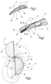
Fig. 1 die erfindungsgemäße Gewebeschere in einer ersten perspektivischen Ansicht, -
Fig. 2 die Gewebeschere nachFig. 1 in einer zweiten perspektivischen Ansicht sowie ein speisendes Gerät in Prinzipdarstellung, -
Fig. 3 eine Branche der Gewebeschere nachFig. 1 und 2 , -
Fig. 4 die Gewebeschere nachFig. 2 in einer perspektivischen ausschnittsweisen Darstellung, -
Fig. 5 die Gewebeschere nachFig. 4 geschnitten entlang der Linie V-V in vereinfachter Darstellung unter Weglassung von Gelenk und Handhebel; unter Darstellung des sich im Einsatz ergebenden Stromflusses, -
Fig. 6 die geschnittenen Branchen ähnlichFig. 4 vor dem Schnitt nebst sich ergebendem Stromfluss und -
Fig. 7 die Gewebeschere nachFig. 4 am Schnittpunkt in einer Darstellung ähnlichFig. 5 und6 . - In
Fig. 1 ist eine Gewebeschere 10 veranschaulicht, die dazu dient, biologisches Gewebe zu durchtrennen und, falls gewünscht, die dabei entstehenden Gewebesäume durch Koagulation bzw. Kauterisation zu versiegeln. Die Gewebeschere 10 weist eine erste Branche 11 und eine zweite Branche 12 auf, die jeweils in Handhebel 13, 14 übergehen, die an ihren Enden Griffteile 15, 16 oder sonstige Handhabungsmittel aufweisen können. Die Branchen 11, 12 sind an einem Gelenk 17 schwenkbar aneinander gehalten, so dass die Handhebel 13, 14 aufeinander zu und voneinander weg schwenkbar sind. - Die Gewebeschere 10 ist mit einem elektrischen Anschluss 18 versehen, zu dem ein doppelter oder zwei einfache Steckkontaktmittel 19, 20 gehören, der / die an einem Griffteil 15, 16 oder an beiden angeordnet ist / sind. Die Stecckontaktmittel sind vorzugsweise Steckstifte, an die Leitungen 21, 22 anschließbar sind, wie sie aus
Fig. 2 schematisch hervorgehen und die mittels eines ersten Pols 43 und eines zweiten Pols 44 zum Anschluss an ein speisendes elektrisches Gerät 23 dienen. - Das elektrische Gerät 23 enthält einen HF-Generator 24, der hochfrequente elektrische Spannung (vorzugsweise zwischen 200 kHz und 4 MHz) abgibt, um damit die Branchen 11, 12 zu speisen, um eine HF-Koagulation des biologischen Gewebes herbeizuführen. Bedienmittel zum gesteuerten Ein- und Ausschalten des Generators 24 sind vorhanden, in
Fig. 2 jedoch nicht gesondert veranschaulicht. - In
Fig. 3 ist die erste Branche 11 gesondert veranschaulicht. Sie weist eine Gleitfläche 25 auf, die im Wesentlichen eben ausgebildet ist und sich über den durch eine Bohrung 26 markierten Gelenkbereich 27 hinaus erstreckt. Die Gleitfläche 25 ist vorzugsweise im Wesentlichen eben ausgebildet und erstreckt sich bis zu dem distalen Ende der Branche 11 hin. Die Gleitfläche 25 schließt an eine Schneidkante 28 der Branche 11 an und erstreckt sich bis zur gegenüberliegenden Kante 29. Die Gleitfläche 25 kann, wie dargestellt, unterbrechungsfrei ausgebildet und mit einer Hartstoffschicht 30 versehen sein. Die Hartstoffschicht 30 schließt mindestens an die Schneidkante 28 an und kann sich im Weiteren unterbrechungsfrei über die gesamte Gleitfläche 25 erstrecken. Insbesondere kann sich die Hartstoffschicht 30 bis zu der Kante 29 hin erstrecken. Die Kante 29 ist der Schneidkante 28 gegenüber angeordnet. Außerdem kann die Hartstoffschicht 30 Teile der sonstigen Oberfläche der Branche 11 einnehmen. - Die Hartstoffschicht 30 ist eine elektrisch leitende Schicht, wie beispielsweise eine Titannitridschicht oder eine andere insbesondere elektrisch leitende Hartstoffschicht (Titancarbid, Titancarbonitrid usw.).
-
Fig. 4 veranschaulicht die Branche 11 in Verbindung mit der Branche 12, die an dem Gelenk 17 durch einen Niet 31, eine Schraube oder dergleichen Verbindungsmittel schwenkbar miteinander verbunden sind. Das Verbindungsmittel ist an seiner Außenseite mit einer Isolation versehen. Dadurch wird ein ungewollter Stromfluss vermieden. Die zweite Branche 12 ist an ihrer der ersten Branche 11 zugewandten Gleitfläche 32 mit einer keramischen Schicht 33 (Fig. 5 ) versehen, die sich von der Hartstoffschicht 30 chemisch und/oder strukturell unterscheidet. Die keramische Schicht 33 bildet eine Gleitfläche 34, die sich bis zu dem distalen Ende der zweiten Branche 12 erstreckt. Außerdem erstreckt sich die keramische Schicht 33 und somit die Gleitfläche 34 von der Schneidkante 35 der zweiten Branche 12 bis zu der gegenüberliegenden Kante 36, die in Längsrichtung der Branche 12 verläuft. Die vorzugsweise ebene Gleitfläche 34 erstreckt sich vorzugsweise von dem distalen Ende der Branche 12 bis zu dem Gelenk 17 und darüber hinaus. Vorzugsweise ist die keramische Schicht 33 vollflächig unterbrechungsfrei ausgebildet, so dass die ansonsten aus Metall bestehende Branche 12 keinen elektrischen Kontakt zu der Branche 11 hat; mit anderen Worten, von dieser elektrisch isoliert ist. Zu diesem Zweck kann ergänzend der Niet 31 aus Kunststoff, aus Keramik oder aus mit Isolationsmaterial umhülltem Metall ausgebildet sein. - Wie
Fig. 5 andeutet, besteht die Branche 11 aus einem einheitlichen Material, z.B. Stahl, der an der Gleitfläche 25 die Hartstoffschicht 30 trägt. Demgegenüber weist die Branche 12 einen Hartmetallkörper 36 auf, der sich über einen erheblichen Teil entlang der Länge der zweiten Branche 12 erstreckt (sieheFig. 4 ). Vorzugsweise erstreckt sich der Hartmetallkörper 36 an dem distalen Ende der Branche 12 von der Schneidkante 35 bis zu der unteren Kante 36. In Richtung zu dem Gelenk 17 kann der Querschnitt des Hartmetallkörpers 36, der gesondert ausFig. 5 hervorgeht, flächenmäßig abnehmen. Die Länge des Hartmetallkörpers 36 ist vorzugsweise größer als die Hälfte des Abstandes des distalen Endes der Branche 12 von dem Gelenk 17. Der Hartmetallkörper 36 kann, wieFig. 5 zeigt, an einer Naht 37 mit einer Trägerstruktur 38 der Branche 12 verbunden sein. Die Trägerstruktur 38 besteht z.B. aus Stahl und verjüngt sich ausgehend von dem vollen Querschnitt der Branche 12 zu dem distalen Ende hin auf Null. Die Trägerstruktur 38 endet vor Erreichen des distalen Endes. Die Naht 37 kann eine Lötnaht, Schweißnaht oder dergleichen stoffliche Verbindung sein. An der von der Gleitfläche 34 abgewandten Rückseite 39 der Branche 12 liegen sowohl der Hartmetallkörper 36 als auch die Trägerstruktur 38 frei zu Tage. Entsprechendes gilt für die Branche 11. Auch dort ist die von der Gleitfläche 25 abgewandte Rückseite 40 unbedeckt. - Wie
Fig. 4 erkennen lässt, sind die Handhebel 13, 14 mit einer elektrisch isolierenden Schicht 41, 42 versehen, die sich vorzugsweise bis zu den Branchen 11, 12 erstreckt, diese aber an den Gleitflächen 25, 34 sowie Bereiche an der Rückseiten 39, 40 frei lässt. Die Abdeckung der Branchen 11, 12 durch die isolierende Schicht 41, 42 kann abhängig vom Verwendungszweck gebildet sein. Es ist möglich, dass nahezu die komplette Rückseite 39, 40 durch die isolierende Schicht 41, 42 abgedeckt ist und die Branchen nur im Bereich des distalen Endes ohne isolierende Schicht ausgebildet sind. - Die insoweit beschriebene Gewebeschere 10 arbeitet wie folgt:
- In den
Fig. 5 ,6 und 7 sind die Branchen 11, 12, geschnitten entlang der inFig. 4 eingetragenen Schnittlinie V-VII, in verschiedenen Schließstadien veranschaulicht. -
Fig. 5 zeigt die Branchen 11, 12, nachdem sie nicht weiter veranschaulichtes biologisches Gewebe gefasst haben und dabei sind, dieses vor dem Durchtrennen mechanisch unter Druck zu setzen. Wenn nun gleichzeitig der Generator 24 aktiviert wird, erzeugt dieser eine hochfrequente elektrische Durchströmung des Gewebes, deren Stromlinien inFig. 6 gestrichelt angedeutet sind. Die Stromdichte nimmt mit dem Fortschreiten des Schnittes zu, wieFig. 7 veranschaulicht. Durch die elektrisch isolierende Wirkung der keramischen Schicht 33 wird ein elektrischer Kurschluss an den Schneidkanten 28, 35 vermieden. In unmittelbarer Nähe der Schneidkanten 28, 35 ergibt sich jedoch eine hohe Stromdichte, die das Gewebe erhitzt und koaguliert. Die in der entstehenden Wärme denaturierenden Eiweiße haben Klebepotential. Würden diese an den Branchen 11, 12 anhaften oder festkleben, würde dies zu einer Behinderung der Arbeit und im schlimmsten Fall zur Unterbrechung des Stromflusses führen. In der Folge wäre die Koagulationswirkung der Gewebeschere nicht mehr vorhanden oder sehr stark eingeschränkt, was wiederum zu einem qualitativ schlechtem Ergebnis führen würde. Eine durch denaturiertes Eiweiß verschmutzte Branche beeinflusst die Koagulationsfunktion der Gewebeschere massiv. Da der Anwender diese Beeinflussung möglicherweise nicht sofort erkennt, kann es dazu führen, dass er weiterhin Gewebe trennt, (die Schneidefunktion wird nicht beeinflusst) ohne dabei die Gefäße erfolgreich zu versiegeln. Im Ergebnis kann es deshalb zu Blutungen kommen. Der Hartmetallkörper 36, dessen Wärmeleitfähigkeit höher ist als die Wärmeleitfähigkeit von Stahl, wirkt dem Anhaften von Gewebe entgegen. Der Hartmetallkörper 36 bewirkt eine wirksame Kühlung der aus Stahl hergestellten Branche 12 und deren keramischen Schicht 33. Dies ergibt in Verbindung mit der haftungsmindernden Hartstoffschicht 30, deren Kühlung durch diese Schicht selbst, sowie gegebenenfalls durch die Branche erfolgt, ein verbessertes Schneide- bzw. Koagulationsergebnis. Insbesondere können die Verhältnisse so eingestellt werden, dass die Kühlwirkung der Hartstoffschicht 30 in Verbindung mit der aus Stahl ausgebildeten Branche 11 vergleichbar ist mit der Kühlwirkung der Kombination aus der keramischen Schicht 33 und dem Hartmetallkörper 36. Die geringe Wärmeleitfähigkeit der keramischen Schicht 33 wird durch die hohe Wärmeleitfähigkeit des Hartmetallkörpers 36 ausgeglichen. - Der fortgesetzte Schnitt führt zu einem Bild der elektrischen Durchströmung wie in
Fig. 5 angedeutet. Obwohl die Branchen 11, 12 strukturell und elektrisch asymmetrisch ausgebildet sind, ergibt sich an den schneidkantennahen Bereichen der Rückseiten 39, 40 eine vergleichbare elektrische Durchströmung und somit eine vergleichbare Koagulationswirkung. - Eine Gewebeschere 10 mit verbesserter Standfestigkeit und verbesserter Handhabung weist zwei baulich und elektrisch unterschiedliche Branchen 11, 12 auf. Während die erste Branche 11 seitens ihrer Gleitfläche 25 mit einer metallkeramischen Hartstoffschicht 30, wie beispielsweise Titannitrid versehen ist, ist die zweite Gleitfläche 34 der zweiten Branche 12 mit einer elektrisch nicht leitenden keramischen Schicht 33 versehen. Die Werkstoffpaarung ergibt eine große mechanische Abriebfestigkeit im Lager 17 und an den Schneidkanten 28, 35. Mindestens eine der Branchen, insbesondere die Branche 12 kann zur verbesserten Kühlung und/oder zur Scharfhaltung der Schneidkante 35 (28) mit einem Hartmetallkörper 36 versehen sein, um ein Erhitzen der Branchen 11, 12 während der Koagulation und ein Ankleben des Gewebes zu verhindern.
-
10 Gewebeschere 11 erste Branche 12 zweite Branche 13, 14 Handhebel 15, 16 Griffteil 17 Gelenk 18 elektrischer Anschluss 19, 20 Steckkontaktmittel 21, 22 Leitungen 23 Gerät 24 Generator 25 erste Gleitfläche 26 Bohrung 27 Gelenkbereich 28 Schneidkante der ersten Branche 11 29 der Schneidkante 28 gegenüberliegende Kante 30 Hartstoffschicht 31 Niet 32 zweite Gleitfläche 33 keramische Schicht 34 zweite Gleitfläche 35 Schneidkante der zweiten Branche 12 36 Hartmetallkörper 37 Naht 38 Trägerstruktur 39, 40 Rückseiten 41, 42 Isolierende Schicht 43, 44 Erster Pol, zweiter Pol
Claims (11)
- Gewebeschere (10) zum Durchtrennen von biologischem Gewebemit einer ersten Branche (11), die eine erste Gleitfläche (25) und eine von der Gleitfläche (25) abgewandte Rückseite (40) aufweist, die an einer ersten Schneidkante (28) endet,mit einer zweiten, eine Trägerstruktur (38) aufweisenden Branche (12), mit der ein Hartmetallkörper (36) verbunden ist und die eine Rückseite (39) und eine zweite Gleitfläche (34) aufweist, die an einer zweiten Schneidkante (35) endet, wobei an der zweiten Gleitfläche (34) eine keramische Schicht (33) vorgesehen ist, wobei der Träger (38) aus Stahl besteht und der Hartmetallkörper (36) eine höhere Wärmeleitfähigkeit als Stahl besitzt,mit einem Gelenk (17), an dem die beiden Branchen (11, 12) schwenkbar miteinander verbunden sind, so dass die Gleitflächen (25, 34) aufeinander zu weisen und die erste Schneidkante (28) an der zweiten Schneidkante (35) vorbei bewegbar ist,wobei an der ersten Gleitfläche (28) eine elektrisch leitende Hartstoffschicht (30) angeordnet und die an der zweiten Gleitfläche (34) vorgesehene keramische Schicht (33) von der Hartstoffschicht (30) der ersten Gleitfläche (28) verschieden ist und dass der Hartmetallkörper (36) mit der Gleitfläche (34) in wärmeaustauschendem Kontakt steht und an der von der Gleitfläche (34) weg weisenden Rückseite (39) der Branche (12) frei liegt so dass an der Rückseite (39) der Branche (12) sowohl der Hartmetallkörper (36) als auch die Trägerstruktur (38) frei liegen und die Rückseite (40) unbedeckt ist.
- Gewebeschere nach einem der vorstehenden Ansprüche, wobei der Hartmetallkörper (36) sich über die gesamte Länge der Schneidkante (35) erstreckt.
- Gewebeschere nach Anspruch 1 und 2, wobei der Hartmetallkörper (36) und der Träger (38) über eine Naht (37) miteinander verbunden sind.
- Gewebeschere nach Anspruch 3, wobei die Naht (37) eine Löt- oder Schweißnaht ist.
- Gewebeschere nach Anspruch 3 oder 4, wobei sich die Naht (37) in einer Richtung von dem Gelenk (17) weg erstreckt.
- Gewebeschere nach einem der vorstehenden Ansprüche, wobei die Keramikschicht (33) die Naht (37) bedeckend ausgebildet ist.
- Gewebeschere nach einem der vorstehenden Ansprüche, wobei sich die erste Gleitfläche (25) und die Hartstoffschicht (33) durch das Gelenk (17) hindurch erstrecken.
- Gewebeschere nach einem der vorstehenden Ansprüche, wobei sich die zweite Gleitfläche (34) und die Keramikschicht (33) durch das Gelenk (17) hindurch erstrecken.
- Gewebeschere nach einem der vorstehenden Ansprüche, wobei die erste Branche (11) und die zweite Branche (12) jeweils mit einem Handhebel (13, 14) verbunden sind.
- Gewebeschere nach einem der vorstehenden Ansprüche, wobei die Handhebel (13, 14) mit einer elektrischen Isolierschicht (41, 42) versehen sind.
- Gewebeschere nach einem der vorstehenden Ansprüche, wobei die erste Branche (11) mit einem ersten Pol (43) eines elektrischen Geräts (24) und die zweite Branche (12) mit einem zweiten Pol (44) des elektrischen Geräts (24) verbindbar ausgebildet ist.
Priority Applications (8)
| Application Number | Priority Date | Filing Date | Title |
|---|---|---|---|
| PL15161680.2T PL3075340T3 (pl) | 2015-03-30 | 2015-03-30 | Nożyce chirurgiczne do tkanki biologicznej |
| EP15161680.2A EP3075340B1 (de) | 2015-03-30 | 2015-03-30 | Gewebeschere für biologisches Gewebe |
| BR102016006136-9A BR102016006136B1 (pt) | 2015-03-30 | 2016-03-21 | Tesoura para tecido para cortar tecido biológico |
| KR1020160033314A KR102515702B1 (ko) | 2015-03-30 | 2016-03-21 | 생물학적 조직을 위한 조직 가위 |
| US15/078,642 US10512502B2 (en) | 2015-03-30 | 2016-03-23 | Tissue scissors for biological tissue |
| CN201610182481.1A CN105997233B (zh) | 2015-03-30 | 2016-03-28 | 用于生物组织的组织剪 |
| RU2016111733A RU2701768C2 (ru) | 2015-03-30 | 2016-03-29 | Тканевые ножницы для биологической ткани |
| JP2016069453A JP6713806B2 (ja) | 2015-03-30 | 2016-03-30 | 生物組織用組織はさみ |
Applications Claiming Priority (1)
| Application Number | Priority Date | Filing Date | Title |
|---|---|---|---|
| EP15161680.2A EP3075340B1 (de) | 2015-03-30 | 2015-03-30 | Gewebeschere für biologisches Gewebe |
Publications (3)
| Publication Number | Publication Date |
|---|---|
| EP3075340A1 EP3075340A1 (de) | 2016-10-05 |
| EP3075340C0 EP3075340C0 (de) | 2023-08-02 |
| EP3075340B1 true EP3075340B1 (de) | 2023-08-02 |
Family
ID=52780461
Family Applications (1)
| Application Number | Title | Priority Date | Filing Date |
|---|---|---|---|
| EP15161680.2A Active EP3075340B1 (de) | 2015-03-30 | 2015-03-30 | Gewebeschere für biologisches Gewebe |
Country Status (8)
| Country | Link |
|---|---|
| US (1) | US10512502B2 (de) |
| EP (1) | EP3075340B1 (de) |
| JP (1) | JP6713806B2 (de) |
| KR (1) | KR102515702B1 (de) |
| CN (1) | CN105997233B (de) |
| BR (1) | BR102016006136B1 (de) |
| PL (1) | PL3075340T3 (de) |
| RU (1) | RU2701768C2 (de) |
Families Citing this family (7)
| Publication number | Priority date | Publication date | Assignee | Title |
|---|---|---|---|---|
| DE102016013771A1 (de) | 2015-11-18 | 2017-05-18 | Asahi Glass Company, Limited | Siebdruckverfahren, Siebdruckeinrichtung, Verfahren zum Herstellen eines Basiselements mit einer Druckschicht sowie Basiselement |
| CN106857032B (zh) * | 2017-03-20 | 2020-07-03 | 中国水利水电科学研究院 | 一种农作物电凝断根刀和系统 |
| WO2020004667A1 (ja) * | 2018-06-29 | 2020-01-02 | ワークソリューション株式会社 | 医療器具、医療装置、医療器具の製造方法、及び、金属製物品 |
| CN109091203B (zh) * | 2018-07-06 | 2020-05-01 | 陕西省肿瘤医院 | 一种包围胶粘式肿瘤切除剪 |
| CN109429762A (zh) * | 2018-12-21 | 2019-03-08 | 刘伟芳 | 电加热消毒自动修枝剪 |
| US10993764B1 (en) | 2020-01-14 | 2021-05-04 | Microline Surgical, Inc. | Insulating grips for minimally invasive surgical instruments |
| CN115568939B (zh) * | 2022-12-09 | 2023-05-05 | 山东百多安医疗器械股份有限公司 | 一种多功能的复合陶瓷双极电刀 |
Citations (2)
| Publication number | Priority date | Publication date | Assignee | Title |
|---|---|---|---|---|
| US6106542A (en) * | 1998-01-23 | 2000-08-22 | Microsurgical Laboratories, Inc. | Surgical forceps |
| US6312430B1 (en) * | 1996-10-28 | 2001-11-06 | Endoscopic Concepts, Inc. | Bipolar electrosurgical end effectors |
Family Cites Families (24)
| Publication number | Priority date | Publication date | Assignee | Title |
|---|---|---|---|---|
| US5151842A (en) | 1991-04-19 | 1992-09-29 | General Electric Company | Switchboards and panelboards having interlock and load selection capabilities |
| US5324289A (en) * | 1991-06-07 | 1994-06-28 | Hemostatic Surgery Corporation | Hemostatic bi-polar electrosurgical cutting apparatus and methods of use |
| US5484436A (en) * | 1991-06-07 | 1996-01-16 | Hemostatic Surgery Corporation | Bi-polar electrosurgical instruments and methods of making |
| DE4212053C1 (de) | 1992-04-10 | 1996-01-11 | Erbe Elektromedizin | Chirurgisches Instrument |
| US6447511B1 (en) * | 1994-12-13 | 2002-09-10 | Symbiosis Corporation | Bipolar endoscopic surgical scissor blades and instrument incorporating the same |
| GB9425781D0 (en) * | 1994-12-21 | 1995-02-22 | Gyrus Medical Ltd | Electrosurgical instrument |
| US5925039A (en) * | 1996-06-12 | 1999-07-20 | Iti Medical Technologies, Inc. | Electrosurgical instrument with conductive ceramic or cermet and method of making same |
| US5801110A (en) * | 1997-04-07 | 1998-09-01 | Miltex Instrument Company | Ceramic composition for coating surgical and dental instruments |
| US5925043A (en) | 1997-04-30 | 1999-07-20 | Medquest Products, Inc. | Electrosurgical electrode with a conductive, non-stick coating |
| US6726686B2 (en) * | 1997-11-12 | 2004-04-27 | Sherwood Services Ag | Bipolar electrosurgical instrument for sealing vessels |
| US7267677B2 (en) * | 1998-10-23 | 2007-09-11 | Sherwood Services Ag | Vessel sealing instrument |
| DE19855812C2 (de) * | 1998-12-03 | 2001-05-03 | Aesculap Ag & Co Kg | Chirurgische Bipolarschere |
| US6974452B1 (en) * | 2000-01-12 | 2005-12-13 | Clinicon Corporation | Cutting and cauterizing surgical tools |
| RU2261065C2 (ru) | 2003-05-19 | 2005-09-27 | Турушев Андрей Михайлович | Устройство для электрокоагуляции биологических тканей |
| US7771424B2 (en) * | 2005-03-16 | 2010-08-10 | Starion Instruments | Integrated metalized ceramic heating element for use in a tissue cutting and sealing device |
| US8449537B2 (en) | 2006-12-29 | 2013-05-28 | St. Jude Medical, Atrial Fibrillation Division, Inc. | Ablation catheter with thermally mediated catheter body for mitigating blood coagulation and creating larger lesion |
| DE102007018993A1 (de) * | 2007-04-21 | 2008-10-30 | Sutter Medizintechnik Gmbh | Bipolare Schere mit gekrümmten Scherblättern |
| EP2486876B1 (de) * | 2009-10-08 | 2020-04-15 | River Seiko Corporation | Scheren für endoskope |
| LV14185B (lv) * | 2010-04-20 | 2010-10-20 | Golsen Limited | Elektroķirurģisks, bipolārs skalpelis |
| US9039732B2 (en) * | 2011-07-11 | 2015-05-26 | Covidien Lp | Surgical forceps |
| EP2554132B1 (de) * | 2011-08-01 | 2016-03-02 | Erbe Elektromedizin GmbH | Gewebefusionsinstrument |
| CN204106191U (zh) * | 2013-08-07 | 2015-01-21 | 柯惠有限合伙公司 | 双极钳 |
| CN203619675U (zh) * | 2013-12-02 | 2014-06-04 | 常州市延陵电子设备有限公司 | 切割闭合系统用钳头 |
| CN204072309U (zh) * | 2014-06-06 | 2015-01-07 | 江苏凝克医疗器械科技有限公司 | 一种手术器具 |
-
2015
- 2015-03-30 EP EP15161680.2A patent/EP3075340B1/de active Active
- 2015-03-30 PL PL15161680.2T patent/PL3075340T3/pl unknown
-
2016
- 2016-03-21 BR BR102016006136-9A patent/BR102016006136B1/pt not_active IP Right Cessation
- 2016-03-21 KR KR1020160033314A patent/KR102515702B1/ko active Active
- 2016-03-23 US US15/078,642 patent/US10512502B2/en active Active
- 2016-03-28 CN CN201610182481.1A patent/CN105997233B/zh not_active Expired - Fee Related
- 2016-03-29 RU RU2016111733A patent/RU2701768C2/ru active
- 2016-03-30 JP JP2016069453A patent/JP6713806B2/ja not_active Expired - Fee Related
Patent Citations (2)
| Publication number | Priority date | Publication date | Assignee | Title |
|---|---|---|---|---|
| US6312430B1 (en) * | 1996-10-28 | 2001-11-06 | Endoscopic Concepts, Inc. | Bipolar electrosurgical end effectors |
| US6106542A (en) * | 1998-01-23 | 2000-08-22 | Microsurgical Laboratories, Inc. | Surgical forceps |
Also Published As
| Publication number | Publication date |
|---|---|
| JP6713806B2 (ja) | 2020-06-24 |
| EP3075340C0 (de) | 2023-08-02 |
| EP3075340A1 (de) | 2016-10-05 |
| KR102515702B1 (ko) | 2023-03-31 |
| JP2016190033A (ja) | 2016-11-10 |
| BR102016006136B1 (pt) | 2022-03-08 |
| PL3075340T3 (pl) | 2023-11-20 |
| CN105997233A (zh) | 2016-10-12 |
| BR102016006136A2 (pt) | 2016-10-25 |
| RU2016111733A (ru) | 2017-10-02 |
| US10512502B2 (en) | 2019-12-24 |
| US20160287320A1 (en) | 2016-10-06 |
| CN105997233B (zh) | 2020-12-22 |
| RU2701768C2 (ru) | 2019-10-01 |
| KR20160117202A (ko) | 2016-10-10 |
| RU2016111733A3 (de) | 2019-04-22 |
Similar Documents
| Publication | Publication Date | Title |
|---|---|---|
| EP3075340A1 (de) | Gewebeschere für biologisches Gewebe | |
| DE69719581T2 (de) | Bipolare Schere | |
| DE69209146T2 (de) | Hämostatisches, bipolares, elektrochirurgisches Schneidgerät | |
| EP1778112B1 (de) | Elektrochirurgisches instrument | |
| DE69633614T2 (de) | Bipolare elektrochirurgische Schere | |
| EP1079755B1 (de) | Chirurgische bipolarschere | |
| DE10201569B4 (de) | Chirurgisches Instrument | |
| DE69533288T2 (de) | Alternative stromwege für ein bipolares chirurgisches schneidwerkzeug | |
| EP3769707B1 (de) | Elektrodenanordnung | |
| DE102007053359B3 (de) | Chirurgisches Instrument | |
| EP2522291B1 (de) | Elektrochirurgisches Instrument | |
| EP2060238A1 (de) | Koagulationsinstrument | |
| DE112018007745B4 (de) | Behandlungsinstrument | |
| EP2907463A1 (de) | Chirurgisches Instrument mit Elektrodenträger | |
| DE102019108140A1 (de) | Bipolares elektrochirurgisches Werkzeug | |
| EP2679186A1 (de) | Instrument zur Gefäßfusion und -trennung | |
| EP3351198B1 (de) | Instrument zur gefässversiegelung | |
| DE69828988T2 (de) | Elektochirurgische elektrode ein elektrisches feld konzentrierend | |
| DE102008032511B4 (de) | Elektrochirurgisches Gerät mit Sicherungseinrichtung | |
| DE112018001314T5 (de) | Ultrapolare elektrochirurgische klinge mit leitenden kontakten oben, unten, an den seiten und an der schneide der klinge | |
| DE112017004470T5 (de) | Monopolare elektrochirurgische klinge und elektrochirurgische klingenanordnung | |
| DE112018001166T5 (de) | Ultrapolare elektrochirurgische klinge und ultrapolare elektrochirurgische klingenanordnung mit leitfähigen schneidkanten und ober- und unterseitigen leitfähigen oberflächen | |
| EP0998879A1 (de) | Instrument für die Hochfrequenzchirurgie | |
| EP3173044B1 (de) | Chirurgische vaporisationselektrode | |
| DE102019108141A1 (de) | Bipolares elektrochirurgisches Werkzeug |
Legal Events
| Date | Code | Title | Description |
|---|---|---|---|
| PUAI | Public reference made under article 153(3) epc to a published international application that has entered the european phase |
Free format text: ORIGINAL CODE: 0009012 |
|
| 17P | Request for examination filed |
Effective date: 20150330 |
|
| AK | Designated contracting states |
Kind code of ref document: A1 Designated state(s): AL AT BE BG CH CY CZ DE DK EE ES FI FR GB GR HR HU IE IS IT LI LT LU LV MC MK MT NL NO PL PT RO RS SE SI SK SM TR |
|
| AX | Request for extension of the european patent |
Extension state: BA ME |
|
| RAP1 | Party data changed (applicant data changed or rights of an application transferred) |
Owner name: ERBE ELEKTROMEDIZIN GMBH |
|
| STAA | Information on the status of an ep patent application or granted ep patent |
Free format text: STATUS: EXAMINATION IS IN PROGRESS |
|
| 17Q | First examination report despatched |
Effective date: 20180413 |
|
| GRAP | Despatch of communication of intention to grant a patent |
Free format text: ORIGINAL CODE: EPIDOSNIGR1 |
|
| STAA | Information on the status of an ep patent application or granted ep patent |
Free format text: STATUS: GRANT OF PATENT IS INTENDED |
|
| INTG | Intention to grant announced |
Effective date: 20230317 |
|
| GRAS | Grant fee paid |
Free format text: ORIGINAL CODE: EPIDOSNIGR3 |
|
| GRAA | (expected) grant |
Free format text: ORIGINAL CODE: 0009210 |
|
| STAA | Information on the status of an ep patent application or granted ep patent |
Free format text: STATUS: THE PATENT HAS BEEN GRANTED |
|
| AK | Designated contracting states |
Kind code of ref document: B1 Designated state(s): AL AT BE BG CH CY CZ DE DK EE ES FI FR GB GR HR HU IE IS IT LI LT LU LV MC MK MT NL NO PL PT RO RS SE SI SK SM TR |
|
| REG | Reference to a national code |
Ref country code: GB Ref legal event code: FG4D Free format text: NOT ENGLISH |
|
| REG | Reference to a national code |
Ref country code: CH Ref legal event code: EP |
|
| REG | Reference to a national code |
Ref country code: DE Ref legal event code: R096 Ref document number: 502015016515 Country of ref document: DE |
|
| REG | Reference to a national code |
Ref country code: IE Ref legal event code: FG4D Free format text: LANGUAGE OF EP DOCUMENT: GERMAN |
|
| U01 | Request for unitary effect filed |
Effective date: 20230803 |
|
| U07 | Unitary effect registered |
Designated state(s): AT BE BG DE DK EE FI FR IT LT LU LV MT NL PT SE SI Effective date: 20230809 |
|
| PG25 | Lapsed in a contracting state [announced via postgrant information from national office to epo] |
Ref country code: GR Free format text: LAPSE BECAUSE OF FAILURE TO SUBMIT A TRANSLATION OF THE DESCRIPTION OR TO PAY THE FEE WITHIN THE PRESCRIBED TIME-LIMIT Effective date: 20231103 |
|
| PG25 | Lapsed in a contracting state [announced via postgrant information from national office to epo] |
Ref country code: IS Free format text: LAPSE BECAUSE OF FAILURE TO SUBMIT A TRANSLATION OF THE DESCRIPTION OR TO PAY THE FEE WITHIN THE PRESCRIBED TIME-LIMIT Effective date: 20231202 |
|
| PG25 | Lapsed in a contracting state [announced via postgrant information from national office to epo] |
Ref country code: RS Free format text: LAPSE BECAUSE OF FAILURE TO SUBMIT A TRANSLATION OF THE DESCRIPTION OR TO PAY THE FEE WITHIN THE PRESCRIBED TIME-LIMIT Effective date: 20230802 Ref country code: NO Free format text: LAPSE BECAUSE OF FAILURE TO SUBMIT A TRANSLATION OF THE DESCRIPTION OR TO PAY THE FEE WITHIN THE PRESCRIBED TIME-LIMIT Effective date: 20231102 Ref country code: IS Free format text: LAPSE BECAUSE OF FAILURE TO SUBMIT A TRANSLATION OF THE DESCRIPTION OR TO PAY THE FEE WITHIN THE PRESCRIBED TIME-LIMIT Effective date: 20231202 Ref country code: HR Free format text: LAPSE BECAUSE OF FAILURE TO SUBMIT A TRANSLATION OF THE DESCRIPTION OR TO PAY THE FEE WITHIN THE PRESCRIBED TIME-LIMIT Effective date: 20230802 Ref country code: GR Free format text: LAPSE BECAUSE OF FAILURE TO SUBMIT A TRANSLATION OF THE DESCRIPTION OR TO PAY THE FEE WITHIN THE PRESCRIBED TIME-LIMIT Effective date: 20231103 |
|
| PG25 | Lapsed in a contracting state [announced via postgrant information from national office to epo] |
Ref country code: ES Free format text: LAPSE BECAUSE OF FAILURE TO SUBMIT A TRANSLATION OF THE DESCRIPTION OR TO PAY THE FEE WITHIN THE PRESCRIBED TIME-LIMIT Effective date: 20230802 |
|
| PG25 | Lapsed in a contracting state [announced via postgrant information from national office to epo] |
Ref country code: SM Free format text: LAPSE BECAUSE OF FAILURE TO SUBMIT A TRANSLATION OF THE DESCRIPTION OR TO PAY THE FEE WITHIN THE PRESCRIBED TIME-LIMIT Effective date: 20230802 Ref country code: RO Free format text: LAPSE BECAUSE OF FAILURE TO SUBMIT A TRANSLATION OF THE DESCRIPTION OR TO PAY THE FEE WITHIN THE PRESCRIBED TIME-LIMIT Effective date: 20230802 Ref country code: ES Free format text: LAPSE BECAUSE OF FAILURE TO SUBMIT A TRANSLATION OF THE DESCRIPTION OR TO PAY THE FEE WITHIN THE PRESCRIBED TIME-LIMIT Effective date: 20230802 Ref country code: CZ Free format text: LAPSE BECAUSE OF FAILURE TO SUBMIT A TRANSLATION OF THE DESCRIPTION OR TO PAY THE FEE WITHIN THE PRESCRIBED TIME-LIMIT Effective date: 20230802 Ref country code: SK Free format text: LAPSE BECAUSE OF FAILURE TO SUBMIT A TRANSLATION OF THE DESCRIPTION OR TO PAY THE FEE WITHIN THE PRESCRIBED TIME-LIMIT Effective date: 20230802 |
|
| REG | Reference to a national code |
Ref country code: DE Ref legal event code: R097 Ref document number: 502015016515 Country of ref document: DE |
|
| PLBE | No opposition filed within time limit |
Free format text: ORIGINAL CODE: 0009261 |
|
| STAA | Information on the status of an ep patent application or granted ep patent |
Free format text: STATUS: NO OPPOSITION FILED WITHIN TIME LIMIT |
|
| 26N | No opposition filed |
Effective date: 20240503 |
|
| REG | Reference to a national code |
Ref country code: CH Ref legal event code: PL |
|
| U90 | Renewal fees not paid: noting of loss of rights |
Free format text: RENEWAL FEE NOT PAID FOR YEAR 10 Effective date: 20241016 |
|
| PG25 | Lapsed in a contracting state [announced via postgrant information from national office to epo] |
Ref country code: MC Free format text: LAPSE BECAUSE OF FAILURE TO SUBMIT A TRANSLATION OF THE DESCRIPTION OR TO PAY THE FEE WITHIN THE PRESCRIBED TIME-LIMIT Effective date: 20230802 |
|
| GBPC | Gb: european patent ceased through non-payment of renewal fee |
Effective date: 20240330 |
|
| PG25 | Lapsed in a contracting state [announced via postgrant information from national office to epo] |
Ref country code: MC Free format text: LAPSE BECAUSE OF FAILURE TO SUBMIT A TRANSLATION OF THE DESCRIPTION OR TO PAY THE FEE WITHIN THE PRESCRIBED TIME-LIMIT Effective date: 20230802 |
|
| PG25 | Lapsed in a contracting state [announced via postgrant information from national office to epo] |
Ref country code: GB Free format text: LAPSE BECAUSE OF NON-PAYMENT OF DUE FEES Effective date: 20240330 |
|
| PG25 | Lapsed in a contracting state [announced via postgrant information from national office to epo] |
Ref country code: IE Free format text: LAPSE BECAUSE OF NON-PAYMENT OF DUE FEES Effective date: 20240330 |
|
| PG25 | Lapsed in a contracting state [announced via postgrant information from national office to epo] |
Ref country code: IE Free format text: LAPSE BECAUSE OF NON-PAYMENT OF DUE FEES Effective date: 20240330 Ref country code: GB Free format text: LAPSE BECAUSE OF NON-PAYMENT OF DUE FEES Effective date: 20240330 Ref country code: CH Free format text: LAPSE BECAUSE OF NON-PAYMENT OF DUE FEES Effective date: 20240331 |
|
| U93 | Unitary patent lapsed |
Free format text: RENEWAL FEE NOT PAID Effective date: 20240331 |
|
| PG25 | Lapsed in a contracting state [announced via postgrant information from national office to epo] |
Ref country code: CY Free format text: LAPSE BECAUSE OF FAILURE TO SUBMIT A TRANSLATION OF THE DESCRIPTION OR TO PAY THE FEE WITHIN THE PRESCRIBED TIME-LIMIT; INVALID AB INITIO Effective date: 20150330 |
|
| PG25 | Lapsed in a contracting state [announced via postgrant information from national office to epo] |
Ref country code: HU Free format text: LAPSE BECAUSE OF FAILURE TO SUBMIT A TRANSLATION OF THE DESCRIPTION OR TO PAY THE FEE WITHIN THE PRESCRIBED TIME-LIMIT; INVALID AB INITIO Effective date: 20150330 |
|
| PG25 | Lapsed in a contracting state [announced via postgrant information from national office to epo] |
Ref country code: PL Free format text: LAPSE BECAUSE OF NON-PAYMENT OF DUE FEES Effective date: 20240330 |
|
| PG25 | Lapsed in a contracting state [announced via postgrant information from national office to epo] |
Ref country code: TR Free format text: LAPSE BECAUSE OF FAILURE TO SUBMIT A TRANSLATION OF THE DESCRIPTION OR TO PAY THE FEE WITHIN THE PRESCRIBED TIME-LIMIT Effective date: 20230802 |