EP3075426A1 - Ausblasung - Google Patents
Ausblasung Download PDFInfo
- Publication number
- EP3075426A1 EP3075426A1 EP15831038.3A EP15831038A EP3075426A1 EP 3075426 A1 EP3075426 A1 EP 3075426A1 EP 15831038 A EP15831038 A EP 15831038A EP 3075426 A1 EP3075426 A1 EP 3075426A1
- Authority
- EP
- European Patent Office
- Prior art keywords
- stretchable
- end part
- stretchable body
- pipe
- pipe body
- Prior art date
- Legal status (The legal status is an assumption and is not a legal conclusion. Google has not performed a legal analysis and makes no representation as to the accuracy of the status listed.)
- Withdrawn
Links
- 238000007664 blowing Methods 0.000 claims abstract description 9
- 239000000463 material Substances 0.000 description 18
- 230000001105 regulatory effect Effects 0.000 description 18
- 230000036541 health Effects 0.000 description 8
- 239000002537 cosmetic Substances 0.000 description 7
- 230000000844 anti-bacterial effect Effects 0.000 description 2
- 230000008859 change Effects 0.000 description 2
- 238000004519 manufacturing process Methods 0.000 description 2
- 238000012549 training Methods 0.000 description 2
- 238000004026 adhesive bonding Methods 0.000 description 1
- 238000005452 bending Methods 0.000 description 1
- 238000013461 design Methods 0.000 description 1
- 230000006872 improvement Effects 0.000 description 1
- 238000003780 insertion Methods 0.000 description 1
- 230000037431 insertion Effects 0.000 description 1
- 239000002184 metal Substances 0.000 description 1
- 238000000034 method Methods 0.000 description 1
- 230000004048 modification Effects 0.000 description 1
- 238000012986 modification Methods 0.000 description 1
- 229920001296 polysiloxane Polymers 0.000 description 1
- 230000008569 process Effects 0.000 description 1
- 239000011347 resin Substances 0.000 description 1
- 229920005989 resin Polymers 0.000 description 1
- 229910001220 stainless steel Inorganic materials 0.000 description 1
Images



Classifications
-
- A—HUMAN NECESSITIES
- A63—SPORTS; GAMES; AMUSEMENTS
- A63B—APPARATUS FOR PHYSICAL TRAINING, GYMNASTICS, SWIMMING, CLIMBING, OR FENCING; BALL GAMES; TRAINING EQUIPMENT
- A63B23/00—Exercising apparatus specially adapted for particular parts of the body
- A63B23/18—Exercising apparatus specially adapted for particular parts of the body for improving respiratory function
-
- A—HUMAN NECESSITIES
- A61—MEDICAL OR VETERINARY SCIENCE; HYGIENE
- A61M—DEVICES FOR INTRODUCING MEDIA INTO, OR ONTO, THE BODY; DEVICES FOR TRANSDUCING BODY MEDIA OR FOR TAKING MEDIA FROM THE BODY; DEVICES FOR PRODUCING OR ENDING SLEEP OR STUPOR
- A61M16/00—Devices for influencing the respiratory system of patients by gas treatment, e.g. ventilators; Tracheal tubes
- A61M16/08—Bellows; Connecting tubes ; Water traps; Patient circuits
- A61M16/0866—Passive resistors therefor
-
- A—HUMAN NECESSITIES
- A61—MEDICAL OR VETERINARY SCIENCE; HYGIENE
- A61M—DEVICES FOR INTRODUCING MEDIA INTO, OR ONTO, THE BODY; DEVICES FOR TRANSDUCING BODY MEDIA OR FOR TAKING MEDIA FROM THE BODY; DEVICES FOR PRODUCING OR ENDING SLEEP OR STUPOR
- A61M16/00—Devices for influencing the respiratory system of patients by gas treatment, e.g. ventilators; Tracheal tubes
-
- A—HUMAN NECESSITIES
- A63—SPORTS; GAMES; AMUSEMENTS
- A63H—TOYS, e.g. TOPS, DOLLS, HOOPS OR BUILDING BLOCKS
- A63H37/00—Jokes; Confetti, streamers, or other dance favours ; Cracker bonbons or the like
-
- A—HUMAN NECESSITIES
- A63—SPORTS; GAMES; AMUSEMENTS
- A63H—TOYS, e.g. TOPS, DOLLS, HOOPS OR BUILDING BLOCKS
- A63H5/00—Musical or noise- producing devices for additional toy effects other than acoustical
Definitions
- the present invention relates to a blowout, particularly, an economical blowout.
- a blowout has been widely known as a "fukimodoshi" toy since a long time ago, which includes a stretchable body (pouch-like portion) having a tube shape, and a wire spring arranged along the longitudinal directions of the stretchable body. If air is blown into the stretchable body from an end thereof, then the stretchable body is stretched, while the stretchable body is curled into a spiral by the elastic force of the wire spring when air is not blown into it.
- the blowout is mainly utilized as a toy for children, but a blowout utilizable for health promotion, medical treatment, cosmetic treatment and the like is also known (e.g., refer to Patent Document 1).
- This type of blowout has a mouthpiece arranged at the air-blowing part thereof, the mouthpiece being formed of an antibacterial, flexible material and being attachable to and detachable from the blowout, so that the blowout can be kept hygienic even if it is repeatedly utilized over a long period of time.
- the stretchable body is generally formed by a sheet of paper and may be degraded after the blowout is repeatedly utilized. Specifically, the stretchable body may not be stretched straight or not be curled into a spiral.
- the stretchable body is united by means of tape or the like to another portion (such as a pipe body). If the stretchable body is degraded, then the entire blowout needs disposing of, even though another such portion is not degraded, which is uneconomical. Still further, for the purpose of health promotion, cosmetic treatment or the like, a user has to keep utilizing a blowout over a long period of time. Hence, every time the stretchable body is degraded, the user has to replace the blowout itself and thereby bear a heavy economic burden.
- a blowout is blown to stretch a stretchable body thereof, and this blowing force (required exhaling force) depends mainly upon the elastic force of a spring of the stretchable body.
- the stretchable body needs to have a suitable length such that the stretchable body will not be stretched over the full length unless a suitable quantity of air is blown therein.
- the stretchable body is united to another portion, and hence, if a user wants to utilize a blowout which differs in required exhaling force (elastic force) or required quantity of air, then the user has to purchase an entire blowout anew and bear a heavy economic burden, thereby making the blowout unhandy.
- a blowout according to claim 1 includes: a stretchable body having a tube shape and changeable in shape; a wire body having elasticity and arranged along the longitudinal directions of the stretchable body; a pipe body having a cylinder shape, one end part of the pipe body being connected to one end part of the stretchable body; and a mouthpiece body having a cylinder shape and connected to the other end part of the pipe body, the mouthpiece body being held by a user in the mouth such that air is blown by the user, in which the stretchable body is stretched by blowing air from the mouthpiece body while the stretchable body is curled into a spiral by the elastic force of the wire body when air is not blown from the mouthpiece body, wherein the one end part of the stretchable body and the one end part of the pipe body are connected by an attaching and detaching means so that the stretchable body is attachable to and detachable from the pipe body.
- the attaching and detaching means is a tightening band having a ring shape and flexible in internal shape; and the one end part of the pipe body is inserted into the one end part of the stretchable body, the tightening band is tightened from above on the one end part of the stretchable body to connect the stretchable body and the pipe body, and the tightening band is loosened to detach the stretchable body from the pipe body.
- the attaching and detaching means is an elastic body having flexibility, the elastic body being arranged in the one end part of the stretchable body such that the elastic body extends in the circumferential directions of the stretchable body; and the one end part of the pipe body is inserted into the one end part of the stretchable body and thereby is pressed by the elastic body to connect the stretchable body and the pipe body, and the pipe body is drawn from the stretchable body to detach the stretchable body from the pipe body.
- the attaching and detaching means is constituted by a first thread engagement portion provided in the one end part of the stretchable body and a second thread engagement portion provided in the one end part of the pipe body, the first thread engagement portion being operable to engage with the second thread engagement portion; and the first thread engagement portion engages with the second thread engagement portion to connect the stretchable body and the pipe body, and the first thread engagement portion disengages from the second thread engagement portion to detach the stretchable body from the pipe body.
- the stretchable body is attachable to and detachable from the pipe body. Therefore, even if the blowout is utilized and the stretchable body is degraded, then without disposing of the entire blowout, a new stretchable body can be attached to the pipe body. In short, only the stretchable body may be replaced and the pipe body, the mouthpiece body and the like can be continuously utilized, thereby making the blowout economical. Further, if a user wants to change the required exhaling force or the required quantity of air in accordance with the usage purposes or the like, then the user can attach, to the pipe body, a stretchable body having a desired/specified required exhaling force (elastic force) or required quantity of air. The user does not have to replace the entire blowout, and hence, the user may only purchase a desired stretchable body and attach the stretchable body, thereby lightening the economic burden and making the blowout handy.
- the tightening band is simply tightened or loosened, and thereby, the stretchable body can be securely, easily and quickly attached to or detached from the pipe body.
- the attaching and detaching means is formed by only the tightening band which is a separate body from the stretchable body or the pipe body. Therefore, the conventional stretchable body or pipe body can be directly utilized, thereby reducing the manufacturing cost and hence making the blowout more economical.
- the pipe body is simply inserted into the stretchable body (elastic body) or drawn from the stretchable body, and thereby, the stretchable body can be securely, easily and quickly attached to or detached from the pipe body.
- the first thread engagement portion simply engages with or disengages from the second thread engagement portion, and thereby, the stretchable body can be securely, easily and quickly attached to or detached from the pipe body.
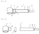
- Figs. 1 to 6 show a first embodiment of the present invention
- Fig. 1 is a perspective view of a blowout 1 according to this embodiment
- Fig. 2 is an exploded perspective view of the blowout 1.
- the blowout 1 is particularly utilizable for health promotion, medical treatment, cosmetic treatment and the like, and mainly includes a stretchable body 2, a wire body 3, a pipe body 4, a mouthpiece body 5, an air regulating body (flow-rate regulating means) 6 and a tightening band (attaching and detaching means) 7.
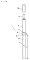
- the stretchable body 2 is a pouch-like portion having a tube shape and changeable in shape, and is formed by sheets of paper 21 and 22 having predetermined material qualities (properties) such as thickness, strength, density (weight per unit area) and durability. As shown in Fig. 3 , the stretchable body 2 has a circle shape in cross section when inflated with air blown into it, and the inner diameter thereof is designed to be slightly larger than the outer diameter of the pipe body 4.
- the stretchable body 2 is formed into a tube by bending a first material 21 having the shape of a substantially rectangular (substantially quadrilateral) sheet (described later).
- a length L of the stretchable body 2 (except the insertion part of the pipe body 4 into the stretchable body 2) is set in accordance with the purposes (what the blowout 1 is used for) such as health promotion, medical treatment and cosmetic treatment, the user conditions such as the oral function condition and the physical condition of a user, or the like.
- the length L of the stretchable body 2 is set such that the quantity of air necessary for stretching out the stretchable body 2 over the full length L equates with a suitable quantity of air preset for a purpose, a user condition or the like.
- the wire body 3 is a wire having elasticity and arranged straight along the longitudinal directions of the stretchable body 2. Specifically, the wire body 3 is formed of stainless-steel wire and is curled into a spiral/coil when not given an external force (when air is not blown into the stretchable body 2). If the wire body 3 is released after straightened by an external force, the wire body 3 returns to the spiral shape by an elastic force of its own.
- the elastic force is set to a predetermined value such that the required exhaling force for stretching the stretchable body 2 becomes a suitable value set in accordance with the purposes, the user conditions or the like, in other words, such that the stretchable body 2 will not be stretched unless the force (exhaled air pressure) by which air is blown from the mouthpiece body 5 is equal to or more than the suitable value (predetermined value).
- suitable value for example, for the purpose of health promotion, different suitable values, in order from low, level 0, level 1 and level 2 can be set in accordance with the oral function condition, physical condition (age) or the like of a user.
- suitable values for the blowing force exhaled air pressure
- suitable values for the blowing force are finely set in accordance with the purposes, the user conditions or the like.
- a plurality of the wire bodies 3 may be provided when the single wire body 3 cannot precisely offer the elastic force equivalent to a predetermined value, or when the plurality of wire bodies 3 can more precisely and easily offer the elastic force equivalent to a predetermined value.
- the plurality of wire bodies 3 could ensure that the stretchable body 2 will not be stretched unless the force by which air is blown from the mouthpiece body 5 is equal to or more than a suitable value (predetermined value).
- a suitable value predetermined value
- one wire body 3 offering the elastic force of a predetermined value is provided for the level 1, and two such wire bodies 3 each offering the elastic force of the same predetermined value are provided for the level 2.
- the wire body 3 is, as shown in Fig. 4 , housed in the stretchable body 2 such that it is located inside of each ring of the spiral of the stretchable body 2.
- the stretchable body 2 is formed by the substantially rectangular first material 21 and the long-strip shaped second material 22.
- the first material 21 is shaped into a tube by placing one end part 21a of the first material 21 on top of the other end part 21b of the first material 21 and gluing the one end part 21a to the other end part 21b.
- the wire body 3 is arranged on the external surface (outer surface) of an overlap part 21c between the one end part 21a and the other end part 21b.
- the second material 22 is glued/joined to the first material 21 such that the second material 22 covers the whole external surface of the overlap part 21c, and thereby, the wire body 3 is united to the stretchable body 2.
- the wire body 3 is arranged on the overlap part 21c between the one end part 21a and the other end part 21b of the first material 21, and then, the second material 22 is arranged on the wire body 3. Therefore, the wire body 3 is strongly held between the two materials 21 and 22, and thereby, is securely united to the stretchable body 2.
- Fig. 4 shows that the two wire bodies 3 are provided, and the number of the wire bodies 3 is set as previously described.
- the pipe body 4 is a pipe portion which has a cylinder shape and one end part 41 of which is connected to one end part 23 of the stretchable body 2.
- the pipe body 4 is a cylindrical body formed by a piece of thick paper having a specified quality of material, and as shown in Figs. 1 and 2 , the one end part 41 is inserted into the one end part 23 of the stretchable body 2 and connected thereto with the tightening band 7 so that the pipe body 4 can be attached to and detached from the stretchable body 2 (as described later).
- the one end part 23 of the stretchable body 2 and the one end part 41 of the pipe body 4 are connected by the tightening band 7 so that the stretchable body 2 can be attached to and detached from the pipe body 4.
- the pipe body 4 has such an inner diameter and a length that a user can hold it easily and blow air easily from the mouthpiece body 5 into the stretchable body 2.
- the mouthpiece body 5 is a mouthpiece portion having a cylinder shape and connected to the other end part (the end part on the opposite side to the stretchable body 2) 42 of the pipe body 4. A user holds the mouthpiece body 5 in the mouth and blows air into the mouthpiece body 5.
- the mouthpiece body 5 is provided inside with the air regulating body 6 regulating the quantity of air flowing toward the stretchable body 2.
- the mouthpiece body 5 is made of resin, and as shown in Fig. 5 , includes a first barrel portion 51, a second barrel portion 52 and a third barrel portion 53.
- the first barrel portion 51 has a cylinder shape slightly tapering to one end thereof.
- the second barrel portion 52 is arranged at the other end of the first barrel portion 51 and has a cone shape small in outer diameter on the side of the first barrel portion 51.
- the third barrel portion 53 is arranged at the end of the second barrel portion 52 on the opposite side to the first barrel portion 51, and has an outer diameter substantially equal to the inner diameter of the pipe body 4.
- the third barrel portion 53 is inserted/pressed into the pipe body 4, and thereby, the mouthpiece body 5 is connected to the pipe body 4.
- the mouthpiece body 5 is formed inside with: a first hole portion 54 located in the first barrel portion 51 and the second barrel portion 52; a second hole portion 55 located in the second barrel portion 52 and the third barrel portion 53; and a third hole portion 56 located in the third barrel portion 53.
- the hole portions 54-56 are concentric with the mouthpiece body 5 and have an inner diameter different from each other. The inner diameter becomes larger in the order of the first hole portion 54, the second hole portion 55 and the third hole portion 56 so that air easily flows toward the stretchable body 2.
- the air regulating body 6 includes a restricting portion 61 united with the mouthpiece body 5 and restricting the flow rate of air, and a restricting body 62 having a ring shape, attached to the mouthpiece body 5 and restricting the flowrate of air.
- the restrictingportion 61 is apartition wall between the first hole portion 54 and the second hole portion 55, and is formed at the center with a first restriction hole 61a. From the first hole portion 54, air flows through the first restriction hole 61a and thereby the flow rate of the air is restricted, so that the air can be sent at a predetermined flow rate to the second hole portion 55.
- the restricting body 62 is a metal disk having an outer diameter substantially equal to the inner diameter of the third hole portion 56, and is inserted/pressed into the third hole portion 56 and attached to the step part between the second hole portion 55 and the third hole portion 56.
- the restricting body 62 is formed at the center with a second restriction hole 62a. From the second hole portion 55, air flows through the second restriction hole 62a and thereby the flow rate of the air is restricted, so that the air is sent at a predetermined flow rate to the third hole portion 56.
- the first restriction hole 61a and the second restriction hole 62a each have a diameter which is approximately half the diameter of the first hole portion 54.
- the restricting portion 61 and the restricting body 62 restrict the flow rate of air blown into them and send the air to the stretchable body 2. Therefore, the stretchable body 2 will not be stretched unless the force by which air is blown from the mouthpiece body 5 is equal to or more than a predetermined value.
- the flow-rate restrictions (the diameters of the restriction holes 61a and 62a) of the restricting portion 61 and the restricting body 62 are set such that the stretchable body 2 will not be stretched unless the force (exhaled air pressure) by which air is blown from the mouthpiece body 5 is equal to or more than a suitable value set in accordance with the purposes, the user conditions or the like.
- an elastic force (elastic modulus) of the wire body 3, the number of wire bodies 3 and a flow-rate restriction (regulated air quantity) by the air regulating body 6 are set such that the required exhaling force for stretching the stretchable body 2 becomes a suitable value set in accordance with the purposes, the user conditions or the like.
- the elastic force of the wire body 3 or the flow-rate restriction by the air regulating body 6 is adjusted such that the stretchable body 2 will not be stretched unless the force (exhaled air pressure) by which air is blown from the mouthpiece body 5 is equal to or more than a suitable value (predetermined value).
- the mouthpiece body 5 is provided with a mouthpiece 57 attachable thereto.
- the mouthpiece 57 is formed of a flexible material (e.g., silicone) subjected to antibacterial treatment. As shown in Fig. 1 , the mouthpiece 57 is a semitransparent cylinder, and into the cylinder, the mouthpiece body 5 is inserted, and then, is pressed into the pipe body 4 so that the mouthpiece 57 can be attached to the mouthpiece body 5.
- the mouthpiece 57 enables a user to hold the mouthpiece body 5 comfortably in the mouth and keeps the mouthpiece body 5 hygienic even if repeatedly utilized over a long period of time.
- the tightening band 7 connects the one end part 23 of the stretchable body 2 and the one end part 41 of the pipe body 4 so that the stretchable body 2 can be attached to and detached from the pipe body 4.
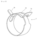
- the tightening band 7 has a ring shape and is flexible in internal shape. As shown in Fig. 6 , the tightening band 7 is formed by a long-strip shaped sheet (spring) having elasticity. In one end part 71 thereof, a long hole 72 is formed along the longitudinal directions, and the other end part 73 thereof is narrower than the one end part 71.
- the tightening band 7 is shaped into a ring (circle) by inserting/setting the other end part 73 into the long hole 72, and then, both end parts 71 and 73 are bent and protruded outward. Both end parts 71 and 73 are pinched to widen the inner diameter (internal shape) of the tightening band 7 so that the tightening band 7 is loosened. Then, both end parts 71 and 73 are released to narrow the inner diameter so that the tightening band 7 is tightened.
- the one end part 41 of the pipe body 4 is inserted into the one end part 23 of the stretchable body 2, and then, the tightening band 7 is tightened from above on the one end part 23 of the stretchable body 2 to connect the stretchable body 2 and the pipe body 4.
- the tightening band 7 is loosened to detach the stretchable body 2 from the pipe body 4.
- the tightening band 7 is set on the middle part of the pipe body 4, and then, the tightening band 7 is moved to the one end part 41 to connect the stretchable body 2 and the pipe body 4 while it is moved (apart) from the one end part 41 to detach the stretchable body 2 from the pipe body 4.
- a user blows air from the mouthpiece body 5 (the mouthpiece 57), and thereby, as shown in Fig. 3 , the air is sent into the stretchable body 2 to stretch the stretchable body 2.
- the stretchable body 2 is curled into a spiral again by the elastic force of the wire body 3. In this process, the stretchable body 2 will not continue stretching unless the force (exhaled air pressure) by which air is blown from the mouthpiece body 5 is equal to or more than a suitable value (predetermined value) set in accordance with the purposes, the user conditions or the like.
- the stretchable body 2 will not stretch out over the full length L. Therefore, a user utilizes the blowout 1 and stretches (blows out) the stretchable body 2 repeatedly, and thereby, the user can take exercise and do training with a blowing force suitable for a purpose, a user condition or the like.
- the stretchable body 2 is attachable to and detachable from the pipe body 4. Therefore, even if the blowout 1 is utilized and the stretchable body 2 is degraded, then without disposing of the entire blowout 1, a new stretchable body 2 can be attached to the pipe body 4. In short, only the stretchable body 2 may be replaced, while the pipe body 4, the mouthpiece body 5 and the like can be continuously utilized, thereby making the blowout 1 economical.
- the tightening band 7 is simply tightened or loosened, and thereby, the stretchable body 2 can be securely, easily and quickly attached to or detached from the pipe body 4.
- the attaching and detaching means is formed by only the tightening band 7 which is a separate body from the stretchable body 2 or the pipe body 4. Therefore, the conventional stretchable body 2 or pipe body 4 can be directly utilized (without an improvement/modification in the stretchable body 2 or the pipe body 4), thereby reducing the manufacturing cost and hence making the blowout 1 more economical.
- a user wants to change the required exhaling force or the required quantity of air in accordance with the usage purposes or the like, then the user can attach, to the pipe body 4, a stretchable body 2 having a desired/specified required exhaling force (elastic force) or required quantity of air.
- the user does not have to replace the entire blowout 1, and hence, the user may only purchase a desired stretchable body 2 and attach the stretchable body 2, thereby lightening the economic burden and making the blowout 1 handy.
- a user may first attach a stretchable body 2 having a low-level required exhaling force (elastic force) to the pipe body 4 and utilize the stretchable body 2.
- step by step after having become accustomed to it the user can replace it with a stretchable body 2 having a high-level required exhaling force. This enables the user to take exercise and do training with a blowing force suitable for a purpose, a user condition or the like.
- the elastic force of the wire body 3 is set to a predetermined value
- the air regulating body 6 is provided for regulating the quantity of air flowing toward the stretchable body 2. Therefore, the stretchable body 2 will not be stretched unless the force (exhaled air pressure) by which air is blown from the mouthpiece body 5 is equal to or more than a predetermined value.
- the required exhaling force (required exhaled-air pressure) for stretching the stretchable body 2 is set using both the elastic force of the wire body 3 and the regulation of the quantity of air (restrictions on the flow rate of air) by the air regulating body 6.
- an optional/specified wire body 3 (stretchable body 2) and air regulating body 6 (pipe body 4) are combined so that the required exhaling force can be precisely adjusted and set to a suitable value for a purpose, a user condition or the like.
- the blowing force exhaled air pressure
- the user conditions such as the oral function condition and the physical condition of a user, or the like
- the specified stretchable body 2 and pipe body 4 are connected so that the required exhaling force can be optionally and precisely adjusted and varied.
- the air regulating body 6 includes the restricting portion 61 and the restricting body 62. Therefore, the flow-rate restrictions of both the restricting portion 61 and the restricting body 62 are adjusted, so that the quantity of air flowing toward the stretchable body 2 can be finely regulated more precisely. Accordingly, the required exhaling force for stretching the stretchable body 2 can be more precisely set to a suitable value for a purpose, a user condition or the like.
- the restricting body 62 is a separate body from the mouthpiece body 5, and hence, the restricting body 62 provided with the second restriction hole 62a having a different diameter can be attached to the mouthpiece body 5. Consequently, the flow-rate restriction (regulated air quantity) by the air regulating body 6 can be adjusted and varied easily without exchanging the mouthpiece body 5.
- the wire body 3 is strongly held between the two materials 21 and 22 and is securely united to the stretchable body 2, and thereby, the elastic force of the wire body 3 is directly transmitted to the stretchable body 2.
- the elastic force set for the wire body 3 directly affects the required exhaling force for stretching the stretchable body 2. Accordingly, simply by setting the elastic force of the wire body 3 to a predetermined value, the required exhaling force can be more precisely set to a desired suitable value.
- the wire body 3 is merely arranged along the stretchable body 2 and glued thereto, then the wire body 3 becomes a separate body from the stretchable body 2, thereby hindering the elastic force of the wire body 3 from being directly transmitted to the stretchable body 2. Consequently, the elastic force (recoiling force) of the stretchable body 2 differs from the elastic force of the wire body 3, thereby affecting and varying the required exhaling force for stretching the stretchable body 2.
- the blowout 1 does not undergo the influence and variation because the wire body 3 is securely united to the stretchable body 2. Accordingly, the required exhaling force can be more precisely set to a desired suitable value.
- the plurality of wire bodies 3 are provided, and the wire bodies adjust and determine the required exhaling force for stretching the stretchable body 2. Accordingly, the required exhaling force can be more precisely set to a desired suitable value.
- Fig. 7 is an exploded perspective view of a blowout 1 according to a second embodiment of the present invention.
- This embodiment is different from the first embodiment in the respect that the attaching and detaching means is formed by a rubber ring (elastic body) 8.
- the other component elements of the second embodiment are given the same reference numerals as those of the first embodiment, as long as the former are identical to the latter. Thus, their description is omitted.
- the rubber ring 8 is an elastic body having flexibility and is arranged in the one end part 23 of the stretchable body 2 such that the rubber ring 8 extends in the circumferential directions of the stretchable body 2.
- the rubber ring 8 is a rubber body having a ring shape and is arranged along the opening of the one end part 23 of the stretchable body 2.
- the elastic force and width thereof are designed so that the stretchable body 2 can be connected securely (without an air leak) to the pipe body 4 and so that a person can easily attach and detach the stretchable body 2 to and from the pipe body 4.
- the one end part 41 of the pipe body 4 is inserted into the one end part 23 of the stretchable body 2 and thereby is pressed by the rubber ring 8 to connect the stretchable body 2 and the pipe body 4.
- the pipe body 4 is drawn from the stretchable body 2 to detach the stretchable body 2 from the pipe body 4.
- the pipe body 4 is simply inserted into the stretchable body 2 (rubber ring 8) or drawn from the stretchable body 2, and thereby, the stretchable body 2 can be securely, easily and quickly attached to or detached from the pipe body 4.
- Fig. 8 is an exploded perspective view of a blowout 1 according to a third embodiment of the present invention.
- This embodiment is different from the first embodiment in the respect that the attaching and detaching means is constituted by an external thread portion (first thread engagement portion) 91 and an internal thread portion (second thread engagement portion) 92.
- the other component elements of the second embodiment are given the same reference numerals as those of the first embodiment, as long as the former are identical to the latter. Thus, their description is omitted.
- the external thread portion 91 is a cylindrical body provided in the one end part 23 of the stretchable body 2 such that the external thread portion 91 is concentric therewith.
- the external thread portion 91 has an external thread formed in the external circumferential surface.
- the internal thread portion 92 has an internal thread formed in the internal circumferential surface of the one end part 41 of the pipe body 4.
- the external thread portion 91 is operable to engage with the internal thread portion 92.
- the external thread portion 91 engages and couples with the internal thread portion 92 to connect the stretchable body 2 and the pipe body 4, and the external thread portion 91 disengages from the internal thread portion 92 to detach the stretchable body 2 from the pipe body 4.
- the external thread portion 91 simply engages with or disengages from the internal thread portion 92, and thereby, the stretchable body 2 can be securely, easily and quickly attached to or detached from the pipe body 4.
- the attaching and detaching means is not limited to those of the above embodiments, and hence, the attaching and detaching means may have any configuration as long as it connects the one end part 23 of the stretchable body 2 and the one end part 41 of the pipe body 4 so that the stretchable body 2 can be attached to and detached from the pipe body 4.
- a one-touch band e.g., a band is tightened by pushing a lever thereof
- a circle/ring shape may be provided in the one end part 23 of the stretchable body 2.
- the one-touch band Into the one-touch band, the one end part 41 of the pipe body 4 is inserted, and then, the one-touch band is tightened or loosened so that the stretchable body 2 can be attached to and detached from the pipe body 4. Further, the stretchable body 2 may have a scale so that a user can visually check easily how much the stretchable body 2 is stretched.
Landscapes
- Health & Medical Sciences (AREA)
- Engineering & Computer Science (AREA)
- General Health & Medical Sciences (AREA)
- Pulmonology (AREA)
- Biomedical Technology (AREA)
- Public Health (AREA)
- Heart & Thoracic Surgery (AREA)
- Hematology (AREA)
- Life Sciences & Earth Sciences (AREA)
- Animal Behavior & Ethology (AREA)
- Emergency Medicine (AREA)
- Anesthesiology (AREA)
- Veterinary Medicine (AREA)
- Physics & Mathematics (AREA)
- Acoustics & Sound (AREA)
- Multimedia (AREA)
- Physical Education & Sports Medicine (AREA)
- Toys (AREA)
- Massaging Devices (AREA)
- Orthopedics, Nursing, And Contraception (AREA)
Applications Claiming Priority (2)
| Application Number | Priority Date | Filing Date | Title |
|---|---|---|---|
| JP2014252847A JP5878229B1 (ja) | 2014-12-15 | 2014-12-15 | 吹き戻し |
| PCT/JP2015/074769 WO2016098396A1 (ja) | 2014-12-15 | 2015-08-31 | 吹き戻し |
Publications (2)
| Publication Number | Publication Date |
|---|---|
| EP3075426A1 true EP3075426A1 (de) | 2016-10-05 |
| EP3075426A4 EP3075426A4 (de) | 2017-10-04 |
Family
ID=55440586
Family Applications (1)
| Application Number | Title | Priority Date | Filing Date |
|---|---|---|---|
| EP15831038.3A Withdrawn EP3075426A4 (de) | 2014-12-15 | 2015-08-31 | Ausblasung |
Country Status (8)
| Country | Link |
|---|---|
| US (1) | US20170216664A1 (de) |
| EP (1) | EP3075426A4 (de) |
| JP (1) | JP5878229B1 (de) |
| KR (1) | KR20170095719A (de) |
| CN (1) | CN106170324A (de) |
| CA (1) | CA2923135A1 (de) |
| TW (1) | TWI573621B (de) |
| WO (1) | WO2016098396A1 (de) |
Families Citing this family (2)
| Publication number | Priority date | Publication date | Assignee | Title |
|---|---|---|---|---|
| CN108245369A (zh) * | 2016-12-29 | 2018-07-06 | 袁杰 | 吹嘴和肺分泌物排出装置 |
| JP6295477B1 (ja) * | 2017-08-23 | 2018-03-20 | 弓場商事株式会社 | 呼気圧測定器 |
Family Cites Families (19)
| Publication number | Priority date | Publication date | Assignee | Title |
|---|---|---|---|---|
| CA263513A (en) * | 1926-08-17 | A. Jackson Edward | Cigarette holder | |
| US392711A (en) * | 1888-11-13 | Spirometer | ||
| US2282056A (en) * | 1940-12-10 | 1942-05-05 | American Merri Lei Corp | Toy |
| US3045671A (en) * | 1959-09-08 | 1962-07-24 | William H Updegraff | Portable inhaler |
| US3321976A (en) * | 1964-08-17 | 1967-05-30 | William C Jones | Expired air collector and method of making the same |
| JPH0512550Y2 (de) * | 1988-08-08 | 1993-03-31 | ||
| GB2219751B (en) * | 1988-06-18 | 1992-07-08 | David Shaw | Practical joke or display device |
| JPH06225977A (ja) * | 1993-02-03 | 1994-08-16 | Yawata Kouundou:Kk | 組立式吹戻しセット |
| US5752502A (en) * | 1993-12-16 | 1998-05-19 | King; Russell Wayne | General purpose aerosol inhalation apparatus |
| JP3985921B2 (ja) * | 1998-08-17 | 2007-10-03 | 株式会社シマノ | グリップ及びこれを備えた釣竿 |
| JP2003210238A (ja) * | 2002-01-18 | 2003-07-29 | Ricoh Elemex Corp | 頭皮洗浄器およびノズルヘッド |
| JP2008298396A (ja) * | 2007-06-01 | 2008-12-11 | Nippon Foil Mfg Co Ltd | 通気口用カバー装置 |
| JP3137944U (ja) | 2007-10-02 | 2007-12-13 | 株式会社ルピナス | 吹き戻し |
| JP3143895U (ja) * | 2008-05-29 | 2008-08-07 | 株式会社ルピナス | 吹き戻しグッズ |
| KR20110031847A (ko) * | 2009-09-21 | 2011-03-29 | 이승수 | 블로우아웃 |
| CN203447775U (zh) * | 2013-05-29 | 2014-02-26 | 浙江万得福塑胶有限公司 | 一种带有2个纸龙的会发光的吹龙玩具 |
| CN203954673U (zh) * | 2014-05-30 | 2014-11-26 | 万文山 | 一种吐舌式玩具口哨 |
| JP5656238B1 (ja) * | 2014-09-03 | 2015-01-21 | 株式会社ルピナス | 吹き戻し |
| JP3194714U (ja) * | 2014-09-25 | 2014-12-04 | 株式会社ルピナス | 吹き戻し |
-
2014
- 2014-12-15 JP JP2014252847A patent/JP5878229B1/ja active Active
-
2015
- 2015-08-31 US US15/026,931 patent/US20170216664A1/en not_active Abandoned
- 2015-08-31 KR KR1020167010790A patent/KR20170095719A/ko not_active Withdrawn
- 2015-08-31 EP EP15831038.3A patent/EP3075426A4/de not_active Withdrawn
- 2015-08-31 CA CA2923135A patent/CA2923135A1/en not_active Abandoned
- 2015-08-31 CN CN201580002248.4A patent/CN106170324A/zh active Pending
- 2015-08-31 WO PCT/JP2015/074769 patent/WO2016098396A1/ja not_active Ceased
- 2015-11-12 TW TW104137329A patent/TWI573621B/zh active
Also Published As
| Publication number | Publication date |
|---|---|
| KR20170095719A (ko) | 2017-08-23 |
| WO2016098396A1 (ja) | 2016-06-23 |
| EP3075426A4 (de) | 2017-10-04 |
| US20170216664A1 (en) | 2017-08-03 |
| TW201628691A (zh) | 2016-08-16 |
| JP5878229B1 (ja) | 2016-03-08 |
| JP2016112164A (ja) | 2016-06-23 |
| CN106170324A (zh) | 2016-11-30 |
| CA2923135A1 (en) | 2016-06-15 |
| TWI573621B (zh) | 2017-03-11 |
Similar Documents
| Publication | Publication Date | Title |
|---|---|---|
| US9616356B2 (en) | Blowout | |
| EP2644221B1 (de) | Tracheostomiekanüle | |
| US20090156322A1 (en) | Grip Training Aid for Golf Clubs | |
| RU2014138495A (ru) | Назальное устройство подачи вещества | |
| EP3075426A1 (de) | Ausblasung | |
| EP4157085B1 (de) | Stimmtrainingsvorrichtung | |
| CN103429291A (zh) | 改进的人工气道 | |
| JP3194714U (ja) | 吹き戻し | |
| US20110214675A1 (en) | Medical tube holder | |
| MX2019013565A (es) | Esnórquel con soporte flotante. | |
| AU2016275355A1 (en) | Methods and devices for supporting an endotracheal tube | |
| JP5890058B1 (ja) | 吹き戻し | |
| US10478093B2 (en) | Exhaled-air pressure measuring device | |
| JP6966820B1 (ja) | 吹き戻し | |
| US20250332478A1 (en) | Semi-occluded vocal tract exercise device with nonlinear-path and adjustable resistance | |
| KR20190055644A (ko) | 줄넘기기가 용이한 줄넘기 | |
| JP6051479B2 (ja) | 呼気判定器、呼気判定ユニットおよび呼気判定器の作動方法 | |
| GB2597104A (en) | Breathwork apparatus | |
| JP2017205227A (ja) | 吹き戻し用支持具および吹き戻し | |
| JP2017205226A (ja) | 吹き戻し |
Legal Events
| Date | Code | Title | Description |
|---|---|---|---|
| PUAI | Public reference made under article 153(3) epc to a published international application that has entered the european phase |
Free format text: ORIGINAL CODE: 0009012 |
|
| 17P | Request for examination filed |
Effective date: 20160216 |
|
| AK | Designated contracting states |
Kind code of ref document: A1 Designated state(s): AL AT BE BG CH CY CZ DE DK EE ES FI FR GB GR HR HU IE IS IT LI LT LU LV MC MK MT NL NO PL PT RO RS SE SI SK SM TR |
|
| AX | Request for extension of the european patent |
Extension state: BA ME |
|
| R17P | Request for examination filed (corrected) |
Effective date: 20160216 |
|
| A4 | Supplementary search report drawn up and despatched |
Effective date: 20170831 |
|
| RIC1 | Information provided on ipc code assigned before grant |
Ipc: A63H 5/00 20060101AFI20170825BHEP |
|
| DAV | Request for validation of the european patent (deleted) | ||
| DAX | Request for extension of the european patent (deleted) | ||
| STAA | Information on the status of an ep patent application or granted ep patent |
Free format text: STATUS: THE APPLICATION IS DEEMED TO BE WITHDRAWN |
|
| 18D | Application deemed to be withdrawn |
Effective date: 20180330 |