EP3075432B1 - Method for carbon dioxide separation - Google Patents
Method for carbon dioxide separation Download PDFInfo
- Publication number
- EP3075432B1 EP3075432B1 EP16164296.2A EP16164296A EP3075432B1 EP 3075432 B1 EP3075432 B1 EP 3075432B1 EP 16164296 A EP16164296 A EP 16164296A EP 3075432 B1 EP3075432 B1 EP 3075432B1
- Authority
- EP
- European Patent Office
- Prior art keywords
- gaseous mixture
- carbon dioxide
- fraction
- gaseous
- oil
- Prior art date
- Legal status (The legal status is an assumption and is not a legal conclusion. Google has not performed a legal analysis and makes no representation as to the accuracy of the status listed.)
- Active
Links
Images

Classifications
-
- B—PERFORMING OPERATIONS; TRANSPORTING
- B01—PHYSICAL OR CHEMICAL PROCESSES OR APPARATUS IN GENERAL
- B01D—SEPARATION
- B01D45/00—Separating dispersed particles from gases or vapours by gravity, inertia, or centrifugal forces
- B01D45/12—Separating dispersed particles from gases or vapours by gravity, inertia, or centrifugal forces by centrifugal forces
- B01D45/16—Separating dispersed particles from gases or vapours by gravity, inertia, or centrifugal forces by centrifugal forces generated by the winding course of the gas stream, the centrifugal forces being generated solely or partly by mechanical means, e.g. fixed swirl vanes
-
- F—MECHANICAL ENGINEERING; LIGHTING; HEATING; WEAPONS; BLASTING
- F25—REFRIGERATION OR COOLING; COMBINED HEATING AND REFRIGERATION SYSTEMS; HEAT PUMP SYSTEMS; MANUFACTURE OR STORAGE OF ICE; LIQUEFACTION SOLIDIFICATION OF GASES
- F25J—LIQUEFACTION, SOLIDIFICATION OR SEPARATION OF GASES OR GASEOUS OR LIQUEFIED GASEOUS MIXTURES BY PRESSURE AND COLD TREATMENT OR BY BRINGING THEM INTO THE SUPERCRITICAL STATE
- F25J3/00—Processes or apparatus for separating the constituents of gaseous or liquefied gaseous mixtures involving the use of liquefaction or solidification
- F25J3/02—Processes or apparatus for separating the constituents of gaseous or liquefied gaseous mixtures involving the use of liquefaction or solidification by rectification, i.e. by continuous interchange of heat and material between a vapour stream and a liquid stream
- F25J3/0228—Processes or apparatus for separating the constituents of gaseous or liquefied gaseous mixtures involving the use of liquefaction or solidification by rectification, i.e. by continuous interchange of heat and material between a vapour stream and a liquid stream characterised by the separated product stream
- F25J3/0266—Processes or apparatus for separating the constituents of gaseous or liquefied gaseous mixtures involving the use of liquefaction or solidification by rectification, i.e. by continuous interchange of heat and material between a vapour stream and a liquid stream characterised by the separated product stream separation of carbon dioxide
-
- B—PERFORMING OPERATIONS; TRANSPORTING
- B01—PHYSICAL OR CHEMICAL PROCESSES OR APPARATUS IN GENERAL
- B01D—SEPARATION
- B01D53/00—Separation of gases or vapours; Recovering vapours of volatile solvents from gases; Chemical or biological purification of waste gases, e.g. engine exhaust gases, smoke, fumes, flue gases, aerosols
- B01D53/002—Separation of gases or vapours; Recovering vapours of volatile solvents from gases; Chemical or biological purification of waste gases, e.g. engine exhaust gases, smoke, fumes, flue gases, aerosols by condensation
-
- B—PERFORMING OPERATIONS; TRANSPORTING
- B01—PHYSICAL OR CHEMICAL PROCESSES OR APPARATUS IN GENERAL
- B01D—SEPARATION
- B01D53/00—Separation of gases or vapours; Recovering vapours of volatile solvents from gases; Chemical or biological purification of waste gases, e.g. engine exhaust gases, smoke, fumes, flue gases, aerosols
- B01D53/24—Separation of gases or vapours; Recovering vapours of volatile solvents from gases; Chemical or biological purification of waste gases, e.g. engine exhaust gases, smoke, fumes, flue gases, aerosols by centrifugal force
-
- B—PERFORMING OPERATIONS; TRANSPORTING
- B01—PHYSICAL OR CHEMICAL PROCESSES OR APPARATUS IN GENERAL
- B01D—SEPARATION
- B01D53/00—Separation of gases or vapours; Recovering vapours of volatile solvents from gases; Chemical or biological purification of waste gases, e.g. engine exhaust gases, smoke, fumes, flue gases, aerosols
- B01D53/34—Chemical or biological purification of waste gases
- B01D53/46—Removing components of defined structure
- B01D53/62—Carbon oxides
-
- E—FIXED CONSTRUCTIONS
- E21—EARTH OR ROCK DRILLING; MINING
- E21B—EARTH OR ROCK DRILLING; OBTAINING OIL, GAS, WATER, SOLUBLE OR MELTABLE MATERIALS OR A SLURRY OF MINERALS FROM WELLS
- E21B43/00—Methods or apparatus for obtaining oil, gas, water, soluble or meltable materials or a slurry of minerals from wells
- E21B43/16—Enhanced recovery methods for obtaining hydrocarbons
- E21B43/164—Injecting CO2 or carbonated water
-
- F—MECHANICAL ENGINEERING; LIGHTING; HEATING; WEAPONS; BLASTING
- F25—REFRIGERATION OR COOLING; COMBINED HEATING AND REFRIGERATION SYSTEMS; HEAT PUMP SYSTEMS; MANUFACTURE OR STORAGE OF ICE; LIQUEFACTION SOLIDIFICATION OF GASES
- F25J—LIQUEFACTION, SOLIDIFICATION OR SEPARATION OF GASES OR GASEOUS OR LIQUEFIED GASEOUS MIXTURES BY PRESSURE AND COLD TREATMENT OR BY BRINGING THEM INTO THE SUPERCRITICAL STATE
- F25J3/00—Processes or apparatus for separating the constituents of gaseous or liquefied gaseous mixtures involving the use of liquefaction or solidification
- F25J3/06—Processes or apparatus for separating the constituents of gaseous or liquefied gaseous mixtures involving the use of liquefaction or solidification by partial condensation
- F25J3/0605—Processes or apparatus for separating the constituents of gaseous or liquefied gaseous mixtures involving the use of liquefaction or solidification by partial condensation characterised by the feed stream
- F25J3/061—Natural gas or substitute natural gas
-
- F—MECHANICAL ENGINEERING; LIGHTING; HEATING; WEAPONS; BLASTING
- F25—REFRIGERATION OR COOLING; COMBINED HEATING AND REFRIGERATION SYSTEMS; HEAT PUMP SYSTEMS; MANUFACTURE OR STORAGE OF ICE; LIQUEFACTION SOLIDIFICATION OF GASES
- F25J—LIQUEFACTION, SOLIDIFICATION OR SEPARATION OF GASES OR GASEOUS OR LIQUEFIED GASEOUS MIXTURES BY PRESSURE AND COLD TREATMENT OR BY BRINGING THEM INTO THE SUPERCRITICAL STATE
- F25J3/00—Processes or apparatus for separating the constituents of gaseous or liquefied gaseous mixtures involving the use of liquefaction or solidification
- F25J3/06—Processes or apparatus for separating the constituents of gaseous or liquefied gaseous mixtures involving the use of liquefaction or solidification by partial condensation
- F25J3/063—Processes or apparatus for separating the constituents of gaseous or liquefied gaseous mixtures involving the use of liquefaction or solidification by partial condensation characterised by the separated product stream
- F25J3/0635—Processes or apparatus for separating the constituents of gaseous or liquefied gaseous mixtures involving the use of liquefaction or solidification by partial condensation characterised by the separated product stream separation of CnHm with 1 carbon atom or more
-
- F—MECHANICAL ENGINEERING; LIGHTING; HEATING; WEAPONS; BLASTING
- F25—REFRIGERATION OR COOLING; COMBINED HEATING AND REFRIGERATION SYSTEMS; HEAT PUMP SYSTEMS; MANUFACTURE OR STORAGE OF ICE; LIQUEFACTION SOLIDIFICATION OF GASES
- F25J—LIQUEFACTION, SOLIDIFICATION OR SEPARATION OF GASES OR GASEOUS OR LIQUEFIED GASEOUS MIXTURES BY PRESSURE AND COLD TREATMENT OR BY BRINGING THEM INTO THE SUPERCRITICAL STATE
- F25J3/00—Processes or apparatus for separating the constituents of gaseous or liquefied gaseous mixtures involving the use of liquefaction or solidification
- F25J3/06—Processes or apparatus for separating the constituents of gaseous or liquefied gaseous mixtures involving the use of liquefaction or solidification by partial condensation
- F25J3/063—Processes or apparatus for separating the constituents of gaseous or liquefied gaseous mixtures involving the use of liquefaction or solidification by partial condensation characterised by the separated product stream
- F25J3/067—Processes or apparatus for separating the constituents of gaseous or liquefied gaseous mixtures involving the use of liquefaction or solidification by partial condensation characterised by the separated product stream separation of carbon dioxide
-
- B—PERFORMING OPERATIONS; TRANSPORTING
- B01—PHYSICAL OR CHEMICAL PROCESSES OR APPARATUS IN GENERAL
- B01D—SEPARATION
- B01D2256/00—Main component in the product gas stream after treatment
- B01D2256/24—Hydrocarbons
-
- B—PERFORMING OPERATIONS; TRANSPORTING
- B01—PHYSICAL OR CHEMICAL PROCESSES OR APPARATUS IN GENERAL
- B01D—SEPARATION
- B01D2257/00—Components to be removed
- B01D2257/50—Carbon oxides
- B01D2257/504—Carbon dioxide
-
- B—PERFORMING OPERATIONS; TRANSPORTING
- B01—PHYSICAL OR CHEMICAL PROCESSES OR APPARATUS IN GENERAL
- B01D—SEPARATION
- B01D2257/00—Components to be removed
- B01D2257/80—Water
-
- F—MECHANICAL ENGINEERING; LIGHTING; HEATING; WEAPONS; BLASTING
- F25—REFRIGERATION OR COOLING; COMBINED HEATING AND REFRIGERATION SYSTEMS; HEAT PUMP SYSTEMS; MANUFACTURE OR STORAGE OF ICE; LIQUEFACTION SOLIDIFICATION OF GASES
- F25J—LIQUEFACTION, SOLIDIFICATION OR SEPARATION OF GASES OR GASEOUS OR LIQUEFIED GASEOUS MIXTURES BY PRESSURE AND COLD TREATMENT OR BY BRINGING THEM INTO THE SUPERCRITICAL STATE
- F25J2205/00—Processes or apparatus using other separation and/or other processing means
- F25J2205/10—Processes or apparatus using other separation and/or other processing means using combined expansion and separation, e.g. in a vortex tube, "Ranque tube" or a "cyclonic fluid separator", i.e. combination of an isentropic nozzle and a cyclonic separator; Centrifugal separation
-
- F—MECHANICAL ENGINEERING; LIGHTING; HEATING; WEAPONS; BLASTING
- F25—REFRIGERATION OR COOLING; COMBINED HEATING AND REFRIGERATION SYSTEMS; HEAT PUMP SYSTEMS; MANUFACTURE OR STORAGE OF ICE; LIQUEFACTION SOLIDIFICATION OF GASES
- F25J—LIQUEFACTION, SOLIDIFICATION OR SEPARATION OF GASES OR GASEOUS OR LIQUEFIED GASEOUS MIXTURES BY PRESSURE AND COLD TREATMENT OR BY BRINGING THEM INTO THE SUPERCRITICAL STATE
- F25J2205/00—Processes or apparatus using other separation and/or other processing means
- F25J2205/20—Processes or apparatus using other separation and/or other processing means using solidification of components
-
- F—MECHANICAL ENGINEERING; LIGHTING; HEATING; WEAPONS; BLASTING
- F25—REFRIGERATION OR COOLING; COMBINED HEATING AND REFRIGERATION SYSTEMS; HEAT PUMP SYSTEMS; MANUFACTURE OR STORAGE OF ICE; LIQUEFACTION SOLIDIFICATION OF GASES
- F25J—LIQUEFACTION, SOLIDIFICATION OR SEPARATION OF GASES OR GASEOUS OR LIQUEFIED GASEOUS MIXTURES BY PRESSURE AND COLD TREATMENT OR BY BRINGING THEM INTO THE SUPERCRITICAL STATE
- F25J2260/00—Coupling of processes or apparatus to other units; Integrated schemes
- F25J2260/80—Integration in an installation using carbon dioxide, e.g. for EOR, sequestration, refrigeration etc.
-
- Y—GENERAL TAGGING OF NEW TECHNOLOGICAL DEVELOPMENTS; GENERAL TAGGING OF CROSS-SECTIONAL TECHNOLOGIES SPANNING OVER SEVERAL SECTIONS OF THE IPC; TECHNICAL SUBJECTS COVERED BY FORMER USPC CROSS-REFERENCE ART COLLECTIONS [XRACs] AND DIGESTS
- Y02—TECHNOLOGIES OR APPLICATIONS FOR MITIGATION OR ADAPTATION AGAINST CLIMATE CHANGE
- Y02C—CAPTURE, STORAGE, SEQUESTRATION OR DISPOSAL OF GREENHOUSE GASES [GHG]
- Y02C20/00—Capture or disposal of greenhouse gases
- Y02C20/40—Capture or disposal of greenhouse gases of CO2
-
- Y—GENERAL TAGGING OF NEW TECHNOLOGICAL DEVELOPMENTS; GENERAL TAGGING OF CROSS-SECTIONAL TECHNOLOGIES SPANNING OVER SEVERAL SECTIONS OF THE IPC; TECHNICAL SUBJECTS COVERED BY FORMER USPC CROSS-REFERENCE ART COLLECTIONS [XRACs] AND DIGESTS
- Y02—TECHNOLOGIES OR APPLICATIONS FOR MITIGATION OR ADAPTATION AGAINST CLIMATE CHANGE
- Y02P—CLIMATE CHANGE MITIGATION TECHNOLOGIES IN THE PRODUCTION OR PROCESSING OF GOODS
- Y02P20/00—Technologies relating to chemical industry
- Y02P20/151—Reduction of greenhouse gas [GHG] emissions, e.g. CO2
Definitions
- This application relates to fractional separation and, more particularly, to methods for fractional separation of a gaseous mixture containing carbon dioxide.
- An oil well typically collects approximately 30 percent of its oil from an underground oil reservoir during the primary recovery phase.
- An additional 20 percent of the oil may be recovered using secondary recovery techniques, such as water flooding that raises the underground pressure.
- Enhanced oil recovery (“EOR") provides a tertiary recovery technique capable of recovering an additional 20 percent or more of the oil from the underground reservoirs.
- Carbon dioxide is typically used as the EOR gas due to its ability to mix with the underground oil and render the oil less viscous and more readily extractable.
- the recovered carbon dioxide typically contains significant quantities of other constituents, such as water vapor, methane, ethane, propane, butane and pentane. Reuse of carbon dioxide contaminated with these constituents in the EOR process is believed to significantly reduce operating efficiency.
- US 2012/031143 relates to removing gaseous contaminants from a feed gas comprising methane and gaseous contaminants, in which the feed gas is cooled to obtain a slurry comprising a solid contaminant, liquid contaminant and a methane enriched gaseous phase.
- the slurry is introduced into a separation device from which the methane enriched gaseous phase is removed.
- the slurry is diluted with liquid contaminant and passed through a heat exchanger wherein solid contaminant is melted into liquid contaminant.
- a stream comprising liquid contaminant is removed from the separation device at a position below the slurry level in the separation device by means of a pump and at least part of the removed liquid contaminant is recovered as a stream product and at least part is recycled and introduced into the separation device to dilute the slurry inside the separation device.
- WO 2011/018620 relates to a method of separating CO 2 from a gas mixture comprising CO 2 including the steps of: (i) compressing and cooling the gas mixture to form a multi-phase mixture stream that includes liquid CO 2 ; (ii) splitting the stream after the compressing and cooling step to form a plurality of sub-streams; (iii) further cooling at least one of the substreams; (iv) recombining a plurality of substreams; and (v) separating a first liquid CO 2 stream from the recombined stream.
- EP 2,149,769 relates to the recovery of carbon dioxide and hydrogen in a concentrated form from a synthesis gas stream comprising hydrogen and carbon dioxide thereby generating a carbon dioxide stream that may be used in a chemical process, or may be sequestered or used for enhanced oil recovery before being ultimately sequestered, and a hydrogen stream that may be used as fuel for a power plant thereby generating electricity or as fuel for a low pressure burner of a fired heater, or as fuel for a reformer or boiler or as a refinery feed stream for upgrading of one or more refinery streams or as a hydrogen feed to a chemical process.
- US 4,664,190 relates to a process in which carbon dioxide is injected into an oil-containing reservoir as an aid in recovering oil from the reservoir.
- Oil can be produced from at least one production well in the reservoir and carbon dioxide-containing hydrocarbon gas will be produced with the oil. Heavy ends are stripped from the carbon dioxide-containing hydrocarbon gas and substantially all of the carbon dioxide in reinjected into the oil-containing reservoir.
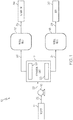
- one embodiment of the disclosed carbon dioxide separation system may include a separation unit 12 and a process gas source 14.
- the system 10 may additionally include a pump 16, a first vessel 18 and a second vessel 20.
- the process gas source 14 may be a source of a gaseous mixture.
- the gaseous mixture may be any gaseous mixture capable of being separated into at least two parts (or fractions) by way of the separation unit 12 in the manners described in greater detail below.
- the gaseous mixture supplied by the gas source 14 may include two or more constituent gases.
- the gaseous mixture supplied may include three constituent gases.
- the gaseous mixture supplied may include four constituent gases.
- the gaseous mixture supplied may include five constituent gases.
- the gaseous mixture supplied may include six or more constituent gases.
- the constituent gases of the gaseous mixture may be gases at standard temperature and pressure (i.e., at 0 °C and 1 bar). However, those skilled in the art will appreciate that the temperature and pressure of the gaseous mixture may vary for various reasons (e.g., temperature and pressure conditions at the source 14) without departing from the scope of the present disclosure. The presence of a liquid and/or solid phase within the gaseous mixture as is travels through the system 10 is contemplated, and does not result in a departure from the scope of the present disclosure.
- the gas source 14 may be an oil well, and the gaseous mixture supplied to the separation unit 12 may be the gaseous effluent from the oil well's gas-oil separator.
- the gaseous mixture obtained from the gas source 14 may be primarily carbon dioxide with a significant concentration of other constituents, such as water vapor and hydrocarbons.
- the hydrocarbon component of the gaseous mixture may be primarily methane, but may also include longer-chain hydrocarbons, such as ethane, propane, butane and pentane.
- the gaseous mixture supplied by the oil well (source 14) may include at least 80 percent by weight carbon dioxide, with the balance being other constituents such as water vapor and hydrocarbons.
- the gaseous mixture supplied by the oil well (source 14) may include at least 85 percent by weight carbon dioxide, with the balance being other constituents such as water vapor and hydrocarbons.
- the gaseous mixture supplied by the oil well (source 14) may include at least 90 percent by weight carbon dioxide, with the balance being other constituents such as water vapor and hydrocarbons.
- the gaseous mixture supplied by the oil well (source 14) may include at least 95 percent by weight carbon dioxide, with the balance being other constituents such as water vapor and hydrocarbons.
- the gas source 14 may be in fluid communication with the separation unit 12 by way of fluid line 22.
- the pump 16 may be provided on fluid line 22 to facilitate the transfer of the gaseous mixture from the gas source 14 to the separation unit 12.
- the pump 16 may be controlled to control the pressure of the gaseous mixture being supplied to the separation unit 12. At this point, those skilled in the art will appreciate that the gaseous mixture may be received from the gas source 14 at a relatively high pressure, particularly when the gas source 14 is an oil well. Therefore, additional pressurization by the pump 16 may not be required or desired.
- the separation unit 12 may receive the gaseous mixture by way of fluid line 22 and may separate the gaseous mixture into at least a first fraction 23 and a second fraction 25.
- Various techniques, such as vortex separation and liquefaction, which are discussed in greater detail below, may be employed by the separation unit 12 to effect separation of the gaseous mixture into at least the first and second fractions 23, 25.
- the first fraction 23 from the separation unit 12 may be sent to the first vessel 18 by way of fluid line 24.
- the first vessel 18 may be a holding vessel, a transportation tanker or the like.
- the first fraction 23 may be sent by fluid line 28 to various downstream applications 30.
- the downstream application 30 may be an oil well application, such as EOR.
- the second fraction 25 from the separation unit 12 may be sent to the second vessel 20 by way of fluid line 26.
- the second vessel 20 may be a holding vessel, a transportation tanker or the like.
- the second fraction 25 may be sent by fluid line 32 to various downstream applications 34.
- the downstream application 34 may be a generator capable of converting the hydrocarbons into electrical energy (e.g., by combustion).
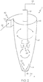
- the separation unit 12 may be (or may include) a vortex separator 40.
- the vortex separator 40 may be any apparatus or system capable of subjecting the gaseous mixture (fluid line 22) to a vortex flow to separate the gaseous mixture into at least a first fraction 23 and a second fraction 25. Therefore, the vortex separator 40 may be configured to receive the gaseous mixture by way of fluid line 22 and cause the gaseous mixture to travel in a vortex fluid path.
- At least two constituent gases of the gaseous mixture supplied by the fluid line 22 may have a difference in molecular weight sufficient to facilitate vortex-induced separation.
- at least one constituent gas of the gaseous mixture may have a molecular weight that is at most 70 percent of the molecular weight of another constituent gas of the gaseous mixture.
- at least one constituent gas of the gaseous mixture may have a molecular weight that is at most 60 percent of the molecular weight of another constituent gas of the gaseous mixture.
- at least one constituent gas of the gaseous mixture may have a molecular weight that is at most 50 percent of the molecular weight of another constituent gas of the gaseous mixture.
- At least one constituent gas of the gaseous mixture may have a molecular weight that is at most 40 percent of the molecular weight of another constituent gas of the gaseous mixture.
- at least one constituent gas of the gaseous mixture may have a molecular weight that is at most 37 percent of the molecular weight of another constituent gas of the gaseous mixture.
- the first fraction 23 may be substantially purified carbon dioxide and the second fraction 25 may include lighter molecular weight constituents, such as water vapor and methane.
- the first fraction 23 may include at least 95 percent by weight carbon dioxide.
- the first fraction 23 may include at least 96 percent by weight carbon dioxide.
- the first fraction 23 may include at least 97 percent by weight carbon dioxide.
- the first fraction 23 may include at least 98 percent by weight carbon dioxide.
- the first fraction 23 may include at least 99 percent by weight carbon dioxide.
- gaseous mixture may cause the relatively higher molecular weight constituents (e.g., carbon dioxide) of the gaseous mixture to separate from the relatively lower molecular weight constituents (e.g., water vapor and methane) by vortex separation.
- the greater momentum of the heavier constituents may urge the heavier constituents radially outward relative to the lighter constituents, thereby providing the opportunity to separate the heavier constituents from the lighter constituents.
- cooling of the gaseous mixture as it expands in the vortex separator 40 may further facilitate separation of at least one constituent from the gaseous mixture.
- sufficient cooling of the gaseous mixture may cause carbon dioxide to change phases (e.g., to liquid), while the other constituents of the gaseous mixture remain in the gaseous phase, thereby simplifying separation.
- the temperature, pressure and flow rate of the gaseous mixture entering the vortex separator 40 may be controllable parameters, and may be controlled to achieve the desired separation.
- the vortex separator 40 may be a static apparatus or system.
- the static vortex separator 40 may be substantially free of moving parts, and may be configured to effect vortex flow of the gaseous mixture based on the shape and configuration of the vortex separator 40 and the angle and direction that the gaseous mixture enters the vortex separator 40 by way of fluid line 22.
- the vortex separator 40 may be configured as a static cyclone separator having generally frustoconical body 42 having a tapered first end 44 and a wider second end 46.
- the first end 44 of the body 42 may define a first exit port 48 coupled to fluid line 24.
- the second end 46 of the body 42 may include an inlet port 50 and a second exit port 52.
- the inlet port 50 may be arranged such that the gaseous mixture circumferentially enters the body 42, thereby directing the gaseous mixture in a vortex flow path.
- the second exit port 52 may be axially aligned with the body 42, and may be generally centered relative to the body 42.
- the second exit port 52 may include a pipe or the like that axially extends, at least partially, into the body 42.
- the gaseous mixture may expand (cool) and may be urged into a vortex flow path.
- the gaseous mixture may separate into a first fraction 23, which may exit the vortex separator 40 by way of fluid line 24, and a second fraction 25, which may exit the vortex separator 40 by way of fluid line 26.
- the vortex separator 40 may be a dynamic apparatus or system.
- a dynamic vortex separator 40 may include fan blades, an impeller, a turbine or the like, which may or may not be connected to a shaft and driven by a motor, and which may urge the gaseous mixture into a vortex flow path.
- the use of both a dynamic vortex separator and a static vortex separator is also contemplated.
- the separation unit 12 may be (or may include) a pressure vessel 60 in which the pressure of the gaseous mixture may be increased to effect liquefaction. Specifically, by increasing the pressure of the gaseous mixture within the pressure vessel 60, the gaseous mixture may separate into at least a first fraction 62 and a second fraction 64. The first fraction 62 may be in a liquid phase and the second fraction 64 may be in a gaseous phase. The first fraction 62 may exit the pressure vessel 60 by way of fluid line 24 and the second fraction 64 may exit the pressure vessel by way of fluid line 26.
- the pressure vessel 60 may be any vessel capable of housing the gaseous mixture at elevated pressures. In one construction, the pressure vessel 60 may be capable of withstanding pressures of at least 80 atm. In another construction, the pressure vessel 60 may be capable of withstanding pressures of at least 90 atm. In another construction, the pressure vessel 60 may be capable of withstanding pressures of at least 100 atm. In another construction, the pressure vessel 60 may be capable of withstanding pressures of at least 150 atm. In yet another construction, the pressure vessel 60 may be capable of withstanding pressures of at least 200 atm.
- the first fraction 62 may be substantially purified carbon dioxide and the second fraction 64 may include lighter molecular weight constituents, such as water vapor and methane.
- the first fraction 62 may include at least 95 percent by weight carbon dioxide.
- the first fraction 62 may include at least 96 percent by weight carbon dioxide.
- the first fraction 62 may include at least 97 percent by weight carbon dioxide.
- the first fraction 62 may include at least 98 percent by weight carbon dioxide.
- the first fraction 62 may include at least 99 percent by weight carbon dioxide.
- the pressure required to achieve liquefaction within the pressure vessel 60 may depend on a variety of factors, including the composition of the gaseous mixture and the concentrations of the various constituents that comprise the gaseous mixture.
- relatively low pressures may be sufficient to achieve liquefaction.
- Carbon dioxide condenses to a liquid at a relatively low partial pressure compared to many other gases, such as hydrocarbons.
- pure carbon dioxide may condense to a liquid at about 1000 psi (68 atm).
- a gaseous mixture containing about 90 percent by weight carbon dioxide (balance methane) may undergo liquefaction at about 1300 psi (88 atm). Therefore, without being limited to any particular theory, it is believed that liquefaction may be a relatively low cost method for separating carbon dioxide from a gaseous mixture, particularly when the gaseous mixture includes a relatively high concentration of carbon dioxide, due to the relatively low pressures required to achieve liquefaction.
- the pressure vessel 60 may be pressurized to a pressure sufficient to condense at least one constituent (e.g., carbon dioxide) of the gaseous mixture.
- the pressure vessel 60 may be pressurized to a pressure of at least 1000 psi (68 atm).
- the pressure vessel 60 may be pressurized to a pressure of at least 1300 psi (88 atm).
- the pressure vessel 60 may be pressurized to a pressure of at least 1400 psi (95 atm).
- the pressure vessel 60 may be pressurized to a pressure of at least 1600 psi (109 atm).
- the pressure vessel 60 may be pressurized to a pressure of at least 1800 psi (122 atm).
- the pressure vessel 60 may be pressurized to a pressure of at most 2000 psi (136 atm).
- the disclosed separation methods may be used to separate carbon dioxide from, for example, the gaseous effluent of an oil well's gas-oil separator, though various other applications for the disclosed methods are also contemplated.
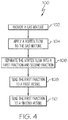
- one embodiment of the disclosed method for separating a gaseous mixture may begin at Block 102 with the step of obtaining a gaseous mixture.
- the gaseous mixture may be a carbon dioxide-containing mixture recovered from an oil well during EOR. Use of other gaseous mixtures is also contemplated.
- the gaseous mixture may be directed into a vortex flow path.
- Various apparatus and systems may be used to apply a vortex flow to the gaseous mixture.
- static or dynamic vortex separators may be used.
- a first fraction e.g., a carbon dioxide-containing fraction
- a second fraction e.g., a light hydrocarbon-containing fraction
- the first fraction may be sent to a first vessel (Block 108) and the second fraction may be sent to a second vessel (Block 110).
- Blocks 104 and 106 may be repeated one or more times, such as by using multiple vortex separators in series, to further purify the first fraction, the second fraction or both fractions.
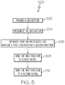
- another embodiment of the disclosed method for separating a gaseous mixture may begin at Block 202 with the step of obtaining a gaseous mixture.
- the gaseous mixture may be a carbon dioxide-containing mixture recovered from an oil well during EOR, and may have a relatively high concentration (e.g., 80 percent by weight or more) of carbon dioxide. Use of other gaseous mixtures is also contemplated.
- the gaseous mixture may be pressurized to a pressure sufficient to form a liquid phase and a gaseous phase.
- the gaseous mixture may be pressurized by pumping the gaseous mixture into a pressure vessel to achieve the desired pressure.
- a first, liquid fraction (e.g., a carbon dioxide-containing fraction) of the gaseous mixture may be separated from a second, gaseous fraction (e.g., a light hydrocarbon-containing fraction), as shown at Block 206.
- the first fraction may be sent to a first vessel (Block 208) and the second fraction may be sent to a second vessel (Block 210).
- the disclosed systems and methods may facilitate separation of one or more constituents (e.g., carbon dioxide) of a gaseous mixture from one or more other constituents of the gaseous mixture without consuming (e.g., burning) any of the constituents.
- the separated first and second fractions may be used in various downstream applications, such as EOR and energy generation.
Landscapes
- Engineering & Computer Science (AREA)
- Chemical & Material Sciences (AREA)
- Chemical Kinetics & Catalysis (AREA)
- Physics & Mathematics (AREA)
- General Chemical & Material Sciences (AREA)
- Oil, Petroleum & Natural Gas (AREA)
- General Engineering & Computer Science (AREA)
- Mechanical Engineering (AREA)
- Thermal Sciences (AREA)
- Analytical Chemistry (AREA)
- Mining & Mineral Resources (AREA)
- Life Sciences & Earth Sciences (AREA)
- Geology (AREA)
- Environmental & Geological Engineering (AREA)
- Fluid Mechanics (AREA)
- General Life Sciences & Earth Sciences (AREA)
- Geochemistry & Mineralogy (AREA)
- Health & Medical Sciences (AREA)
- Biomedical Technology (AREA)
- Carbon And Carbon Compounds (AREA)
- Gas Separation By Absorption (AREA)
- Separation Using Semi-Permeable Membranes (AREA)
- Treating Waste Gases (AREA)
- Physical Or Chemical Processes And Apparatus (AREA)
- Organic Low-Molecular-Weight Compounds And Preparation Thereof (AREA)
Applications Claiming Priority (4)
| Application Number | Priority Date | Filing Date | Title |
|---|---|---|---|
| US201261617574P | 2012-03-29 | 2012-03-29 | |
| US201261617554P | 2012-03-29 | 2012-03-29 | |
| US13/767,115 US9205357B2 (en) | 2012-03-29 | 2013-02-14 | Carbon dioxide separation system and method |
| EP13160170.0A EP2644253B1 (en) | 2012-03-29 | 2013-03-20 | Carbon dioxide separation system and method |
Related Parent Applications (2)
| Application Number | Title | Priority Date | Filing Date |
|---|---|---|---|
| EP13160170.0A Division-Into EP2644253B1 (en) | 2012-03-29 | 2013-03-20 | Carbon dioxide separation system and method |
| EP13160170.0A Division EP2644253B1 (en) | 2012-03-29 | 2013-03-20 | Carbon dioxide separation system and method |
Publications (2)
| Publication Number | Publication Date |
|---|---|
| EP3075432A1 EP3075432A1 (en) | 2016-10-05 |
| EP3075432B1 true EP3075432B1 (en) | 2019-09-18 |
Family
ID=47900937
Family Applications (2)
| Application Number | Title | Priority Date | Filing Date |
|---|---|---|---|
| EP16164296.2A Active EP3075432B1 (en) | 2012-03-29 | 2013-03-20 | Method for carbon dioxide separation |
| EP13160170.0A Active EP2644253B1 (en) | 2012-03-29 | 2013-03-20 | Carbon dioxide separation system and method |
Family Applications After (1)
| Application Number | Title | Priority Date | Filing Date |
|---|---|---|---|
| EP13160170.0A Active EP2644253B1 (en) | 2012-03-29 | 2013-03-20 | Carbon dioxide separation system and method |
Country Status (6)
| Country | Link |
|---|---|
| US (1) | US9205357B2 (es) |
| EP (2) | EP3075432B1 (es) |
| CN (1) | CN103357239B (es) |
| CA (2) | CA2808805C (es) |
| MX (1) | MX337404B (es) |
| RU (2) | RU2656493C2 (es) |
Families Citing this family (14)
| Publication number | Priority date | Publication date | Assignee | Title |
|---|---|---|---|---|
| US10041672B2 (en) * | 2013-12-17 | 2018-08-07 | Schlumberger Technology Corporation | Real-time burner efficiency control and monitoring |
| MY175330A (en) * | 2014-10-23 | 2020-06-19 | Petroliam Nasional Berhad Petronas | Cryogenic centrifugal system and method |
| FI126833B (en) * | 2014-12-30 | 2017-06-15 | Outotec Finland Oy | Sulfur drying |
| WO2017058832A1 (en) | 2015-09-28 | 2017-04-06 | Schlumberger Technology Corporation | Burner monitoring and control systems |
| AU2016412713B2 (en) | 2016-06-28 | 2023-02-02 | Schlumberger Technology B.V. | Well testing systems and methods with mobile monitoring |
| IT201600081329A1 (it) * | 2016-08-02 | 2018-02-02 | Saipem Spa | Processo, dispositivo separatore e impianto per la separazione di una miscela gassosa |
| CN107879315A (zh) * | 2016-09-29 | 2018-04-06 | 浙江览锐智能科技有限公司 | 一种臭氧管的匀流式除湿进气装置 |
| MY195530A (en) * | 2019-05-30 | 2023-01-30 | Petroliam Nasional Berhad Petronas | A System and Method for Handling a Multiple Phase Hydrocarbon Feed |
| CN111537549B (zh) * | 2020-06-08 | 2021-04-13 | 北京大学 | 一种相态连续变化的二氧化碳驱油封存与压裂装置和实验方法 |
| CN111715001B (zh) * | 2020-06-16 | 2022-06-21 | 上海建工四建集团有限公司 | 一种用于净化带粉尘有压气体的方法 |
| CN113586938A (zh) * | 2021-07-20 | 2021-11-02 | 柏宗宪 | 一种二氧化碳驱油用气体增压装置 |
| CA3128992A1 (en) * | 2021-08-26 | 2023-02-26 | De.Mission Inc. | Linear gas separator |
| CN114871078A (zh) * | 2022-05-18 | 2022-08-09 | 三一技术装备有限公司 | 烘箱新风系统 |
| US12228022B1 (en) * | 2023-11-10 | 2025-02-18 | Fmc Technologies, Inc. | Carbon dioxide control system for well control and production |
Citations (1)
| Publication number | Priority date | Publication date | Assignee | Title |
|---|---|---|---|---|
| US4664190A (en) * | 1985-12-18 | 1987-05-12 | Shell Western E&P Inc. | Process for recovering natural gas liquids |
Family Cites Families (75)
| Publication number | Priority date | Publication date | Assignee | Title |
|---|---|---|---|---|
| US3853507A (en) | 1947-12-31 | 1974-12-10 | Atomic Energy Commission | Cold trap unit |
| US3359707A (en) | 1960-06-15 | 1967-12-26 | Jean Olivier Auguste Louis | Method and apparatus for removing co2 and moisture from stale air |
| GB1125505A (en) | 1966-06-23 | 1968-08-28 | Distillers Co Carbon Dioxide | Production of carbon dioxide and argon |
| US3660967A (en) | 1970-09-08 | 1972-05-09 | Union Carbide Corp | Purification of fluid streams by selective adsorption |
| US4094652A (en) | 1975-10-23 | 1978-06-13 | W. R. Grace & Co. | Electrodesorption system for regenerating a dielectric adsorbent bed |
| US4322394A (en) | 1977-10-31 | 1982-03-30 | Battelle Memorial Institute | Adsorbent regeneration and gas separation utilizing microwave heating |
| US4312641A (en) | 1979-05-25 | 1982-01-26 | Pall Corporation | Heat-reactivatable adsorbent gas fractionator and process |
| US4249915A (en) * | 1979-05-30 | 1981-02-10 | Air Products And Chemicals, Inc. | Removal of water and carbon dioxide from air |
| US4832711A (en) | 1982-02-25 | 1989-05-23 | Pall Corporation | Adsorbent fractionator with automatic temperature-sensing cycle control and process |
| US4484933A (en) | 1983-06-14 | 1984-11-27 | Union Carbide Corporation | Process for drying gas streams |
| US4551197A (en) | 1984-07-26 | 1985-11-05 | Guilmette Joseph G | Method and apparatus for the recovery and recycling of condensable gas reactants |
| GB2171927B (en) | 1985-03-04 | 1988-05-25 | Boc Group Plc | Method and apparatus for separating a gaseous mixture |
| JPS62136222A (ja) | 1985-12-10 | 1987-06-19 | Nippon Steel Corp | 混合ガスから特定のガスを吸着分離する方法 |
| ES2003265A6 (es) | 1987-04-21 | 1988-10-16 | Espan Carburos Metal | Procedimiento para la obtencion de co2 y n2 a partir de los gases generados en un motor o turbina de combustion interna |
| US4784672A (en) | 1987-10-08 | 1988-11-15 | Air Products And Chemicals, Inc. | Regeneration of adsorbents |
| US5059405A (en) | 1988-12-09 | 1991-10-22 | Bio-Gas Development, Inc. | Process and apparatus for purification of landfill gases |
| DE4003533A1 (de) | 1989-02-07 | 1990-08-09 | Pero Kg | Verfahren und vorrichtung zur rueckgewinnung von in einem adsorber adsorbierten umweltbelastenden stoffen |
| US5232474A (en) | 1990-04-20 | 1993-08-03 | The Boc Group, Inc. | Pre-purification of air for separation |
| US5100635A (en) | 1990-07-31 | 1992-03-31 | The Boc Group, Inc. | Carbon dioxide production from combustion exhaust gases with nitrogen and argon by-product recovery |
| US5749230A (en) | 1991-01-18 | 1998-05-12 | Engelhard/Icc | Method for creating a humidity gradient within an air conditioned zone |
| JPH0779946B2 (ja) | 1991-09-13 | 1995-08-30 | 工業技術院長 | ガス吸着・脱離制御方法 |
| US5221520A (en) | 1991-09-27 | 1993-06-22 | North Carolina Center For Scientific Research, Inc. | Apparatus for treating indoor air |
| US5233837A (en) | 1992-09-03 | 1993-08-10 | Enerfex, Inc. | Process and apparatus for producing liquid carbon dioxide |
| US5261250A (en) | 1993-03-09 | 1993-11-16 | Polycold Systems International | Method and apparatus for recovering multicomponent vapor mixtures |
| US6332925B1 (en) | 1996-05-23 | 2001-12-25 | Ebara Corporation | Evacuation system |
| US6027548A (en) | 1996-12-12 | 2000-02-22 | Praxair Technology, Inc. | PSA apparatus and process using adsorbent mixtures |
| DE19727376C2 (de) | 1997-06-27 | 2002-07-18 | Daimler Chrysler Ag | Verfahren zur Adsorption von organischen Stoffen in der Luft |
| US6183539B1 (en) | 1998-07-01 | 2001-02-06 | Zeochem Co. | Molecular sieve adsorbent for gas purification and preparation thereof |
| DE69908886T2 (de) | 1998-11-02 | 2003-12-04 | Institut Francais Du Petrole, Rueil-Malmaison | Verfahren zur Herstellung eines Zeoliths des EUO-Typs mittels Vorläufern des Strukturbildners und dessen Verwendung als Isomerisierungskatalysator von Aromaten mit acht Kohlenstoffatomen |
| WO2000038831A1 (en) | 1998-12-31 | 2000-07-06 | Hexablock, Inc. | Magneto absorbent |
| US6293999B1 (en) | 1999-11-30 | 2001-09-25 | Uop Llc | Process for separating propylene from propane |
| JP2001205045A (ja) | 2000-01-25 | 2001-07-31 | Tokyo Electric Power Co Inc:The | 二酸化炭素除去方法および二酸化炭素除去装置 |
| US6621848B1 (en) | 2000-04-25 | 2003-09-16 | The Boeing Company | SECOIL reprocessing system |
| US6502328B1 (en) | 2000-05-17 | 2003-01-07 | Arrow Pneumatics, Inc. | Seal for holding a microwave antenna at a pressurized tank of a gas drying system and method |
| JP3591724B2 (ja) | 2001-09-28 | 2004-11-24 | 株式会社東芝 | 炭酸ガス吸収材および炭酸ガス分離装置 |
| US7122496B2 (en) | 2003-05-01 | 2006-10-17 | Bp Corporation North America Inc. | Para-xylene selective adsorbent compositions and methods |
| US7291271B2 (en) | 2003-12-09 | 2007-11-06 | Separation Design Group, Llc | Meso-frequency traveling wave electro-kinetic continuous adsorption system |
| GB2416389B (en) * | 2004-07-16 | 2007-01-10 | Statoil Asa | LCD liquefaction process |
| EP2409753B1 (en) | 2005-07-28 | 2017-07-19 | Carbon Sink Inc. | Removal of carbon dioxide from air |
| US7591866B2 (en) * | 2006-03-31 | 2009-09-22 | Ranendra Bose | Methane gas recovery and usage system for coalmines, municipal land fills and oil refinery distillation tower vent stacks |
| US7695553B2 (en) | 2006-06-30 | 2010-04-13 | Praxair Technology, Inc. | Twin blowers for gas separation plants |
| US7736416B2 (en) | 2007-02-26 | 2010-06-15 | Hamilton Sundstrand Corporation | Thermally linked molecular sieve beds for CO2 removal |
| US20080268300A1 (en) * | 2007-04-30 | 2008-10-30 | Pfefferle William C | Method for producing fuel and power from a methane hydrate bed using a fuel cell |
| JP5346926B2 (ja) | 2007-05-18 | 2013-11-20 | エクソンモービル リサーチ アンド エンジニアリング カンパニー | 圧縮熱を利用する、排煙からのco2の温度スイング吸着 |
| AU2008254512B2 (en) | 2007-05-18 | 2012-03-01 | Exxonmobil Upstream Research Company | Process for removing a target gas from a mixture of gases by thermal swing adsorption |
| US8616294B2 (en) * | 2007-05-20 | 2013-12-31 | Pioneer Energy, Inc. | Systems and methods for generating in-situ carbon dioxide driver gas for use in enhanced oil recovery |
| PL2192969T3 (pl) | 2007-08-28 | 2015-09-30 | Commw Scient Ind Res Org | Artykuł do ekstrahowania komponentu ze strumienia płynu, sposoby i systemy zawierające go |
| WO2009042244A1 (en) | 2007-09-28 | 2009-04-02 | The Trustees Of Columbia University In The City Of New York | Methods and systems for generating hydgrogen and separating carbon dioxide |
| CA3047633C (en) | 2008-02-19 | 2023-08-01 | Carbon Sink Inc. | Extraction and sequestration of carbon dioxide |
| US8591627B2 (en) | 2009-04-07 | 2013-11-26 | Innosepra Llc | Carbon dioxide recovery |
| WO2009141895A1 (ja) | 2008-05-20 | 2009-11-26 | イビデン株式会社 | 排ガス浄化装置 |
| WO2009149292A1 (en) | 2008-06-04 | 2009-12-10 | Global Research Technologies, Llc | Laminar flow air collector with solid sorbent materials for capturing ambient co2 |
| US8535417B2 (en) | 2008-07-29 | 2013-09-17 | Praxair Technology, Inc. | Recovery of carbon dioxide from flue gas |
| EP2149769A1 (en) * | 2008-07-31 | 2010-02-03 | BP Alternative Energy International Limited | Separation of carbon dioxide and hydrogen |
| WO2010026057A1 (en) * | 2008-09-04 | 2010-03-11 | Alstom Technology Ltd. | Liquefaction of gaseous carbon-dioxide remainders during anti-sublimation process |
| WO2010059268A1 (en) | 2008-11-19 | 2010-05-27 | Murray Kenneth D | Carbon dioxide control device to capture carbon dioxide from vehicle combustion waste |
| DE102008062497A1 (de) | 2008-12-16 | 2010-06-17 | Linde-Kca-Dresden Gmbh | Verfahren und Vorrichtung zur Behandlung eines kohlendioxidhaltigen Gasstroms aus einer Großfeuerungsanlage |
| CN102307642B (zh) * | 2008-12-22 | 2014-03-19 | 缠绕机公司 | 从流体流中去除二氧化碳的方法以及流体分离装置 |
| WO2010079177A2 (en) * | 2009-01-08 | 2010-07-15 | Shell Internationale Research Maatschappij B.V. | Process and apparatus for removing gaseous contaminants from gas stream comprising gaseous contaminants |
| RU89505U1 (ru) * | 2009-03-02 | 2009-12-10 | Общество с ограниченной ответственностью "Научно-исследовательский институт природных газов и газовых технологий - Газпром ВНИИГАЗ" (ООО "Газпром ВНИИГАЗ") | Хранилище газов в горных выработках - "вниигаз" |
| US8500856B2 (en) | 2009-05-08 | 2013-08-06 | Nippon Steel & Sumitomo Metal Corporation | Hybrid adsorbent method of capturing carbon dioxide in gas and apparatus for capturing carbon dioxide in gas |
| WO2011009163A1 (en) * | 2009-07-20 | 2011-01-27 | Calix Limited | Method and system for extracting carbon dioxide from an industrial source of flue gas at atmospheric pressure |
| WO2011018620A2 (en) * | 2009-08-12 | 2011-02-17 | Bp Alternative Energy International Limited | Separation of carbon dioxide from a mixture of gases |
| GB0915954D0 (en) | 2009-09-11 | 2009-10-28 | Airbus Operations Ltd | Desiccant regeneration |
| EP2490789B1 (en) | 2009-10-19 | 2014-08-06 | Lanxess Sybron Chemicals Inc. | Process for carbon dioxide capture via ion exchange resins |
| WO2011053695A1 (en) | 2009-10-28 | 2011-05-05 | Meadwestvaco Corporation | Method and system for reducing emissions from evaporative emissions control systems |
| CA2769687C (en) * | 2010-04-16 | 2014-12-30 | Her Majesty The Queen In Right Of Canada As Represented By The Ministeof Natural Resources | Auto-refrigerated gas separation system for carbon dioxide capture and compression |
| EP2563495B1 (en) | 2010-04-30 | 2019-09-25 | Peter Eisenberger | Method for carbon dioxide capture |
| JP5485812B2 (ja) | 2010-06-24 | 2014-05-07 | 株式会社西部技研 | 二酸化炭素回収装置 |
| CN103096999A (zh) | 2010-07-28 | 2013-05-08 | 萨加斯公司 | 碳捕集喷气发动机 |
| AU2011296633B2 (en) | 2010-09-03 | 2016-07-14 | Twister B.V. | Refining system and method for refining a feed gas stream |
| CN102179153B (zh) * | 2011-04-08 | 2013-04-17 | 上海华畅环保设备发展有限公司 | 烟道气二氧化碳捕集系统尾气旋转流净化方法与装置 |
| WO2013010328A1 (en) | 2011-07-21 | 2013-01-24 | Rht Limited | Air purifier with electric field regeneration |
| US10118122B2 (en) | 2011-08-29 | 2018-11-06 | The Boeing Company | CO2 collection methods and systems |
| US9103549B2 (en) | 2012-08-23 | 2015-08-11 | The Boeing Company | Dual stream system and method for producing carbon dioxide |
-
2013
- 2013-02-14 US US13/767,115 patent/US9205357B2/en active Active
- 2013-03-07 CA CA2808805A patent/CA2808805C/en active Active
- 2013-03-07 CA CA2958697A patent/CA2958697C/en active Active
- 2013-03-20 EP EP16164296.2A patent/EP3075432B1/en active Active
- 2013-03-20 EP EP13160170.0A patent/EP2644253B1/en active Active
- 2013-03-27 MX MX2013003586A patent/MX337404B/es active IP Right Grant
- 2013-03-28 RU RU2016127459A patent/RU2656493C2/ru active
- 2013-03-28 RU RU2013113872/05A patent/RU2595702C2/ru active
- 2013-03-28 CN CN201310104810.7A patent/CN103357239B/zh active Active
Patent Citations (1)
| Publication number | Priority date | Publication date | Assignee | Title |
|---|---|---|---|---|
| US4664190A (en) * | 1985-12-18 | 1987-05-12 | Shell Western E&P Inc. | Process for recovering natural gas liquids |
Also Published As
| Publication number | Publication date |
|---|---|
| CN103357239B (zh) | 2017-04-26 |
| CA2958697A1 (en) | 2013-09-29 |
| RU2656493C2 (ru) | 2018-06-05 |
| EP2644253B1 (en) | 2016-05-25 |
| US20130255486A1 (en) | 2013-10-03 |
| US9205357B2 (en) | 2015-12-08 |
| RU2013113872A (ru) | 2014-10-10 |
| CA2808805C (en) | 2018-08-28 |
| CA2958697C (en) | 2019-12-03 |
| EP2644253A2 (en) | 2013-10-02 |
| EP2644253A3 (en) | 2015-01-14 |
| RU2595702C2 (ru) | 2016-08-27 |
| CN103357239A (zh) | 2013-10-23 |
| EP3075432A1 (en) | 2016-10-05 |
| CA2808805A1 (en) | 2013-09-29 |
| MX337404B (es) | 2016-03-03 |
| MX2013003586A (es) | 2013-10-16 |
Similar Documents
| Publication | Publication Date | Title |
|---|---|---|
| EP3075432B1 (en) | Method for carbon dioxide separation | |
| US7550032B2 (en) | Method for removing contaminating gaseous components from a natural gas stream | |
| US10486100B1 (en) | Coalescer for co-current contactors | |
| EP3377196B1 (en) | Compact subsea dehydration | |
| US10428287B2 (en) | Subsea fluid processing system | |
| US20160236140A1 (en) | Inner Surface Features for Co-Current Contactors | |
| US10087730B2 (en) | Direct steam generator degassing | |
| EP2904201A1 (en) | Multiphase separation system | |
| US9399908B2 (en) | Systems and method for separating dimethyl ether from oil and water | |
| EP2877264A1 (en) | Multiphase separation system | |
| WO2017209757A1 (en) | Two column hydrocarbon recovery from carbon dioxide enhanced oil recovery streams | |
| US20250034978A1 (en) | System and method for separating gases from oil production streams | |
| EA047898B1 (ru) | Способ и система рекуперации энергии при добыче углеводородов | |
| CA2870798A1 (en) | Processes for treating reservoir fluid comprising material produced from a hydrocarbon containing reservoir |
Legal Events
| Date | Code | Title | Description |
|---|---|---|---|
| PUAI | Public reference made under article 153(3) epc to a published international application that has entered the european phase |
Free format text: ORIGINAL CODE: 0009012 |
|
| 17P | Request for examination filed |
Effective date: 20160407 |
|
| AC | Divisional application: reference to earlier application |
Ref document number: 2644253 Country of ref document: EP Kind code of ref document: P |
|
| AK | Designated contracting states |
Kind code of ref document: A1 Designated state(s): AL AT BE BG CH CY CZ DE DK EE ES FI FR GB GR HR HU IE IS IT LI LT LU LV MC MK MT NL NO PL PT RO RS SE SI SK SM TR |
|
| RIN1 | Information on inventor provided before grant (corrected) |
Inventor name: HALL, JOHN C. Inventor name: MAGNUSON, JON A. Inventor name: GALASSO, D. ANTHONY |
|
| STAA | Information on the status of an ep patent application or granted ep patent |
Free format text: STATUS: EXAMINATION IS IN PROGRESS |
|
| 17Q | First examination report despatched |
Effective date: 20181116 |
|
| GRAP | Despatch of communication of intention to grant a patent |
Free format text: ORIGINAL CODE: EPIDOSNIGR1 |
|
| STAA | Information on the status of an ep patent application or granted ep patent |
Free format text: STATUS: GRANT OF PATENT IS INTENDED |
|
| INTG | Intention to grant announced |
Effective date: 20190410 |
|
| GRAS | Grant fee paid |
Free format text: ORIGINAL CODE: EPIDOSNIGR3 |
|
| GRAA | (expected) grant |
Free format text: ORIGINAL CODE: 0009210 |
|
| STAA | Information on the status of an ep patent application or granted ep patent |
Free format text: STATUS: THE PATENT HAS BEEN GRANTED |
|
| AC | Divisional application: reference to earlier application |
Ref document number: 2644253 Country of ref document: EP Kind code of ref document: P |
|
| AK | Designated contracting states |
Kind code of ref document: B1 Designated state(s): AL AT BE BG CH CY CZ DE DK EE ES FI FR GB GR HR HU IE IS IT LI LT LU LV MC MK MT NL NO PL PT RO RS SE SI SK SM TR |
|
| REG | Reference to a national code |
Ref country code: GB Ref legal event code: FG4D |
|
| REG | Reference to a national code |
Ref country code: CH Ref legal event code: EP |
|
| REG | Reference to a national code |
Ref country code: DE Ref legal event code: R096 Ref document number: 602013060842 Country of ref document: DE |
|
| REG | Reference to a national code |
Ref country code: AT Ref legal event code: REF Ref document number: 1180648 Country of ref document: AT Kind code of ref document: T Effective date: 20191015 |
|
| REG | Reference to a national code |
Ref country code: IE Ref legal event code: FG4D |
|
| REG | Reference to a national code |
Ref country code: DE Ref legal event code: R082 Ref document number: 602013060842 Country of ref document: DE Representative=s name: MAIER, LL.M., MICHAEL C., DE Ref country code: DE Ref legal event code: R082 Ref document number: 602013060842 Country of ref document: DE Representative=s name: BOULT WADE TENNANT LLP, DE |
|
| REG | Reference to a national code |
Ref country code: NL Ref legal event code: MP Effective date: 20190918 |
|
| PG25 | Lapsed in a contracting state [announced via postgrant information from national office to epo] |
Ref country code: FI Free format text: LAPSE BECAUSE OF FAILURE TO SUBMIT A TRANSLATION OF THE DESCRIPTION OR TO PAY THE FEE WITHIN THE PRESCRIBED TIME-LIMIT Effective date: 20190918 Ref country code: HR Free format text: LAPSE BECAUSE OF FAILURE TO SUBMIT A TRANSLATION OF THE DESCRIPTION OR TO PAY THE FEE WITHIN THE PRESCRIBED TIME-LIMIT Effective date: 20190918 Ref country code: LT Free format text: LAPSE BECAUSE OF FAILURE TO SUBMIT A TRANSLATION OF THE DESCRIPTION OR TO PAY THE FEE WITHIN THE PRESCRIBED TIME-LIMIT Effective date: 20190918 Ref country code: BG Free format text: LAPSE BECAUSE OF FAILURE TO SUBMIT A TRANSLATION OF THE DESCRIPTION OR TO PAY THE FEE WITHIN THE PRESCRIBED TIME-LIMIT Effective date: 20191218 Ref country code: NO Free format text: LAPSE BECAUSE OF FAILURE TO SUBMIT A TRANSLATION OF THE DESCRIPTION OR TO PAY THE FEE WITHIN THE PRESCRIBED TIME-LIMIT Effective date: 20191218 Ref country code: SE Free format text: LAPSE BECAUSE OF FAILURE TO SUBMIT A TRANSLATION OF THE DESCRIPTION OR TO PAY THE FEE WITHIN THE PRESCRIBED TIME-LIMIT Effective date: 20190918 |
|
| REG | Reference to a national code |
Ref country code: LT Ref legal event code: MG4D |
|
| REG | Reference to a national code |
Ref country code: DE Ref legal event code: R082 Ref document number: 602013060842 Country of ref document: DE Representative=s name: BOULT WADE TENNANT LLP, DE |
|
| PG25 | Lapsed in a contracting state [announced via postgrant information from national office to epo] |
Ref country code: RS Free format text: LAPSE BECAUSE OF FAILURE TO SUBMIT A TRANSLATION OF THE DESCRIPTION OR TO PAY THE FEE WITHIN THE PRESCRIBED TIME-LIMIT Effective date: 20190918 Ref country code: AL Free format text: LAPSE BECAUSE OF FAILURE TO SUBMIT A TRANSLATION OF THE DESCRIPTION OR TO PAY THE FEE WITHIN THE PRESCRIBED TIME-LIMIT Effective date: 20190918 Ref country code: GR Free format text: LAPSE BECAUSE OF FAILURE TO SUBMIT A TRANSLATION OF THE DESCRIPTION OR TO PAY THE FEE WITHIN THE PRESCRIBED TIME-LIMIT Effective date: 20191219 Ref country code: LV Free format text: LAPSE BECAUSE OF FAILURE TO SUBMIT A TRANSLATION OF THE DESCRIPTION OR TO PAY THE FEE WITHIN THE PRESCRIBED TIME-LIMIT Effective date: 20190918 |
|
| REG | Reference to a national code |
Ref country code: AT Ref legal event code: MK05 Ref document number: 1180648 Country of ref document: AT Kind code of ref document: T Effective date: 20190918 |
|
| PG25 | Lapsed in a contracting state [announced via postgrant information from national office to epo] |
Ref country code: PL Free format text: LAPSE BECAUSE OF FAILURE TO SUBMIT A TRANSLATION OF THE DESCRIPTION OR TO PAY THE FEE WITHIN THE PRESCRIBED TIME-LIMIT Effective date: 20190918 Ref country code: EE Free format text: LAPSE BECAUSE OF FAILURE TO SUBMIT A TRANSLATION OF THE DESCRIPTION OR TO PAY THE FEE WITHIN THE PRESCRIBED TIME-LIMIT Effective date: 20190918 Ref country code: PT Free format text: LAPSE BECAUSE OF FAILURE TO SUBMIT A TRANSLATION OF THE DESCRIPTION OR TO PAY THE FEE WITHIN THE PRESCRIBED TIME-LIMIT Effective date: 20200120 Ref country code: NL Free format text: LAPSE BECAUSE OF FAILURE TO SUBMIT A TRANSLATION OF THE DESCRIPTION OR TO PAY THE FEE WITHIN THE PRESCRIBED TIME-LIMIT Effective date: 20190918 Ref country code: AT Free format text: LAPSE BECAUSE OF FAILURE TO SUBMIT A TRANSLATION OF THE DESCRIPTION OR TO PAY THE FEE WITHIN THE PRESCRIBED TIME-LIMIT Effective date: 20190918 Ref country code: IT Free format text: LAPSE BECAUSE OF FAILURE TO SUBMIT A TRANSLATION OF THE DESCRIPTION OR TO PAY THE FEE WITHIN THE PRESCRIBED TIME-LIMIT Effective date: 20190918 Ref country code: RO Free format text: LAPSE BECAUSE OF FAILURE TO SUBMIT A TRANSLATION OF THE DESCRIPTION OR TO PAY THE FEE WITHIN THE PRESCRIBED TIME-LIMIT Effective date: 20190918 Ref country code: ES Free format text: LAPSE BECAUSE OF FAILURE TO SUBMIT A TRANSLATION OF THE DESCRIPTION OR TO PAY THE FEE WITHIN THE PRESCRIBED TIME-LIMIT Effective date: 20190918 |
|
| PG25 | Lapsed in a contracting state [announced via postgrant information from national office to epo] |
Ref country code: SK Free format text: LAPSE BECAUSE OF FAILURE TO SUBMIT A TRANSLATION OF THE DESCRIPTION OR TO PAY THE FEE WITHIN THE PRESCRIBED TIME-LIMIT Effective date: 20190918 Ref country code: IS Free format text: LAPSE BECAUSE OF FAILURE TO SUBMIT A TRANSLATION OF THE DESCRIPTION OR TO PAY THE FEE WITHIN THE PRESCRIBED TIME-LIMIT Effective date: 20200224 Ref country code: CZ Free format text: LAPSE BECAUSE OF FAILURE TO SUBMIT A TRANSLATION OF THE DESCRIPTION OR TO PAY THE FEE WITHIN THE PRESCRIBED TIME-LIMIT Effective date: 20190918 Ref country code: SM Free format text: LAPSE BECAUSE OF FAILURE TO SUBMIT A TRANSLATION OF THE DESCRIPTION OR TO PAY THE FEE WITHIN THE PRESCRIBED TIME-LIMIT Effective date: 20190918 |
|
| REG | Reference to a national code |
Ref country code: DE Ref legal event code: R097 Ref document number: 602013060842 Country of ref document: DE |
|
| PLBE | No opposition filed within time limit |
Free format text: ORIGINAL CODE: 0009261 |
|
| STAA | Information on the status of an ep patent application or granted ep patent |
Free format text: STATUS: NO OPPOSITION FILED WITHIN TIME LIMIT |
|
| PG2D | Information on lapse in contracting state deleted |
Ref country code: IS |
|
| PG25 | Lapsed in a contracting state [announced via postgrant information from national office to epo] |
Ref country code: DK Free format text: LAPSE BECAUSE OF FAILURE TO SUBMIT A TRANSLATION OF THE DESCRIPTION OR TO PAY THE FEE WITHIN THE PRESCRIBED TIME-LIMIT Effective date: 20190918 Ref country code: IS Free format text: LAPSE BECAUSE OF FAILURE TO SUBMIT A TRANSLATION OF THE DESCRIPTION OR TO PAY THE FEE WITHIN THE PRESCRIBED TIME-LIMIT Effective date: 20200119 |
|
| 26N | No opposition filed |
Effective date: 20200619 |
|
| PG25 | Lapsed in a contracting state [announced via postgrant information from national office to epo] |
Ref country code: SI Free format text: LAPSE BECAUSE OF FAILURE TO SUBMIT A TRANSLATION OF THE DESCRIPTION OR TO PAY THE FEE WITHIN THE PRESCRIBED TIME-LIMIT Effective date: 20190918 |
|
| PG25 | Lapsed in a contracting state [announced via postgrant information from national office to epo] |
Ref country code: MC Free format text: LAPSE BECAUSE OF FAILURE TO SUBMIT A TRANSLATION OF THE DESCRIPTION OR TO PAY THE FEE WITHIN THE PRESCRIBED TIME-LIMIT Effective date: 20190918 |
|
| REG | Reference to a national code |
Ref country code: CH Ref legal event code: PL |
|
| REG | Reference to a national code |
Ref country code: BE Ref legal event code: MM Effective date: 20200331 |
|
| PG25 | Lapsed in a contracting state [announced via postgrant information from national office to epo] |
Ref country code: LU Free format text: LAPSE BECAUSE OF NON-PAYMENT OF DUE FEES Effective date: 20200320 |
|
| PG25 | Lapsed in a contracting state [announced via postgrant information from national office to epo] |
Ref country code: IE Free format text: LAPSE BECAUSE OF NON-PAYMENT OF DUE FEES Effective date: 20200320 Ref country code: CH Free format text: LAPSE BECAUSE OF NON-PAYMENT OF DUE FEES Effective date: 20200331 Ref country code: LI Free format text: LAPSE BECAUSE OF NON-PAYMENT OF DUE FEES Effective date: 20200331 |
|
| PG25 | Lapsed in a contracting state [announced via postgrant information from national office to epo] |
Ref country code: BE Free format text: LAPSE BECAUSE OF NON-PAYMENT OF DUE FEES Effective date: 20200331 |
|
| PG25 | Lapsed in a contracting state [announced via postgrant information from national office to epo] |
Ref country code: TR Free format text: LAPSE BECAUSE OF FAILURE TO SUBMIT A TRANSLATION OF THE DESCRIPTION OR TO PAY THE FEE WITHIN THE PRESCRIBED TIME-LIMIT Effective date: 20190918 Ref country code: MT Free format text: LAPSE BECAUSE OF FAILURE TO SUBMIT A TRANSLATION OF THE DESCRIPTION OR TO PAY THE FEE WITHIN THE PRESCRIBED TIME-LIMIT Effective date: 20190918 Ref country code: CY Free format text: LAPSE BECAUSE OF FAILURE TO SUBMIT A TRANSLATION OF THE DESCRIPTION OR TO PAY THE FEE WITHIN THE PRESCRIBED TIME-LIMIT Effective date: 20190918 |
|
| PG25 | Lapsed in a contracting state [announced via postgrant information from national office to epo] |
Ref country code: MK Free format text: LAPSE BECAUSE OF FAILURE TO SUBMIT A TRANSLATION OF THE DESCRIPTION OR TO PAY THE FEE WITHIN THE PRESCRIBED TIME-LIMIT Effective date: 20190918 |
|
| P01 | Opt-out of the competence of the unified patent court (upc) registered |
Effective date: 20230516 |
|
| PGFP | Annual fee paid to national office [announced via postgrant information from national office to epo] |
Ref country code: GB Payment date: 20260327 Year of fee payment: 14 |
|
| PGFP | Annual fee paid to national office [announced via postgrant information from national office to epo] |
Ref country code: DE Payment date: 20260327 Year of fee payment: 14 |
|
| PGFP | Annual fee paid to national office [announced via postgrant information from national office to epo] |
Ref country code: FR Payment date: 20260325 Year of fee payment: 14 |