EP3075454B1 - Centrifugeuse de laboratoire et son procédé de fonctionnement - Google Patents
Centrifugeuse de laboratoire et son procédé de fonctionnement Download PDFInfo
- Publication number
- EP3075454B1 EP3075454B1 EP15162405.3A EP15162405A EP3075454B1 EP 3075454 B1 EP3075454 B1 EP 3075454B1 EP 15162405 A EP15162405 A EP 15162405A EP 3075454 B1 EP3075454 B1 EP 3075454B1
- Authority
- EP
- European Patent Office
- Prior art keywords
- rotor
- product
- acceleration
- rotation
- angular
- Prior art date
- Legal status (The legal status is an assumption and is not a legal conclusion. Google has not performed a legal analysis and makes no representation as to the accuracy of the status listed.)
- Active
Links
Images





Classifications
-
- B—PERFORMING OPERATIONS; TRANSPORTING
- B04—CENTRIFUGAL APPARATUS OR MACHINES FOR CARRYING-OUT PHYSICAL OR CHEMICAL PROCESSES
- B04B—CENTRIFUGES
- B04B5/00—Other centrifuges
- B04B5/12—Centrifuges in which rotors other than bowls generate centrifugal effects in stationary containers
-
- B—PERFORMING OPERATIONS; TRANSPORTING
- B04—CENTRIFUGAL APPARATUS OR MACHINES FOR CARRYING-OUT PHYSICAL OR CHEMICAL PROCESSES
- B04B—CENTRIFUGES
- B04B9/00—Drives specially designed for centrifuges; Arrangement or disposition of transmission gearing; Suspending or balancing rotary bowls
- B04B9/10—Control of the drive; Speed regulating
-
- B—PERFORMING OPERATIONS; TRANSPORTING
- B01—PHYSICAL OR CHEMICAL PROCESSES OR APPARATUS IN GENERAL
- B01D—SEPARATION
- B01D21/00—Separation of suspended solid particles from liquids by sedimentation
- B01D21/26—Separation of sediment aided by centrifugal force or centripetal force
- B01D21/262—Separation of sediment aided by centrifugal force or centripetal force by using a centrifuge
-
- B—PERFORMING OPERATIONS; TRANSPORTING
- B04—CENTRIFUGAL APPARATUS OR MACHINES FOR CARRYING-OUT PHYSICAL OR CHEMICAL PROCESSES
- B04B—CENTRIFUGES
- B04B11/00—Feeding, charging, or discharging bowls
-
- B—PERFORMING OPERATIONS; TRANSPORTING
- B04—CENTRIFUGAL APPARATUS OR MACHINES FOR CARRYING-OUT PHYSICAL OR CHEMICAL PROCESSES
- B04B—CENTRIFUGES
- B04B13/00—Control arrangements specially designed for centrifuges; Program control of centrifuges
-
- B—PERFORMING OPERATIONS; TRANSPORTING
- B04—CENTRIFUGAL APPARATUS OR MACHINES FOR CARRYING-OUT PHYSICAL OR CHEMICAL PROCESSES
- B04B—CENTRIFUGES
- B04B5/00—Other centrifuges
- B04B5/04—Radial chamber apparatus for separating predominantly liquid mixtures, e.g. butyrometers
- B04B5/0407—Radial chamber apparatus for separating predominantly liquid mixtures, e.g. butyrometers for liquids contained in receptacles
- B04B5/0414—Radial chamber apparatus for separating predominantly liquid mixtures, e.g. butyrometers for liquids contained in receptacles comprising test tubes
-
- B—PERFORMING OPERATIONS; TRANSPORTING
- B04—CENTRIFUGAL APPARATUS OR MACHINES FOR CARRYING-OUT PHYSICAL OR CHEMICAL PROCESSES
- B04B—CENTRIFUGES
- B04B7/00—Elements of centrifuges
Definitions
- rotors are used in laboratory centrifuges, which are designed as angular rotors or swing-bucket rotors and rotate about a vertical axis of rotation.
- US 2,821,339 A discloses a laboratory centrifuge in which a rotor is to be rotated at low speed about a horizontally oriented axis of rotation.
- the rotor is supported directly by a drive pin of an electric drive.
- the rotor is designed as a drum with a hollow cylindrical drum wall.
- the drum is closed on the drive side facing by a circular disk-shaped support plate, while it is open on the side facing away from the drive.
- On the drum wall a plurality of circumferentially distributed holders for containers to be centrifuged with samples are held inside.
- the brackets are designed as spring clips, which are formed with two radially inwardly oriented, V-shaped inwardly opening spring arms.
- the containers can be inserted parallel to the axis of rotation of the rotor between spring arms of either a holder or adjacent spring arms of two adjacent holders, whereby the containers are clamped by the spring arms.
- the longitudinal axis of the container is oriented parallel to the axis of rotation of the rotor, wherein a lid or closure of the container is arranged on the side facing away from the drive. It is possible that several drum walls of different diameters can be nested concentrically with each other, whereby the number of containers to be centrifuged with the rotor can be increased.
- the publication US 2008/0182742 A1 discloses a centrifuge in which a plurality of rotors, which are formed in a circular disk, rotate about a common horizontal axis of rotation.
- the rotors can be driven together by means of a common drive or several individual drives, but also during further centrifuging with the other rotors a rotor can be decoupled from the at least one drive, centrifuged samples can be taken from this rotor and the rotor can be removed with new ones Samples can be equipped with subsequent re-drive of the rotor by the associated drive. In this way, centrifuging with one or more rotors need not be interrupted if another rotor is to be loaded or unloaded.
- a loading and unloading of a rotor via a loading and unloading device which is movable via a rail parallel to the axis of rotation, so that the loading and unloading can interact with the different rotors in each case.
- the loading and unloading further has an actuator by means of which a new sample can be supplied from the outside in the direction of the axis of rotation of a holder of the rotor and vice versa From a holder a finished centrifuged sample can be removed in the radial direction from the axis of rotation of the rotor.
- DE 10 2012 201 717 A1 discloses a centrifuge in which several modules each have a rotor.
- the rotor has a horizontal axis of rotation and forms a trough-like receptacle, whose longitudinal axis is oriented parallel to the axis of rotation and which has a U-shaped cross-section with slightly diverging side limbs of the U, wherein the axis of rotation is perpendicular to the plane of extension of the U approximately centrally through the U.
- a plurality of sample containers can be arranged and held one behind the other in the direction of the rotation axis, wherein sample channel longitudinal axes of a plurality of sample containers are arranged parallel to one another in a common plane, which is oriented radially to the axis of rotation.
- the modules have a rotary position sensor for detecting the rotational position of the recording. Using the signal of the rotary position sensor for loading samples into the receptacle and removing samples from the recording after centrifuging, the recording in a loading and unloading placed in which the sample channel longitudinal axes are oriented parallel to the acceleration of gravity.
- Centrifugation is carried out here at speeds of more than 3,000 revolutions per minute, whereby an alternating component of the acceleration acting on the specimens as a result of gravitational acceleration should be a disturbance variable with an influence of less than one percent.
- a balancing device with a balancing mass can be eliminated any imbalance of the rotor.
- the sample carriers to be centrifuged are so-called "gel carts" which have a plurality of sample channels.
- the sample carrier should be held on the receptacle via a latching means.
- the sample carriers can be arranged with such a small distance from the axis of rotation that one end of a sample channel lies on the axis of rotation.
- Loading and / unloading can be done by gripping tools of a loading machine or by means of a pipetting device.
- the loading and unloading in the loading and unloading position of the recording with an introduction of the sample or the sample carrier from above between the side legs of the U-shaped receptacle and removing the sample or the sample carrier after centrifugation also upwards.
- EP 2 835 178 A1 discloses a centrifuge used for washing microtiter plates.
- the microtiter plates are rotated about a horizontal axis of rotation.
- To empty or wash the microtiter are the openings of the microtiter plates oriented radially outward, so that the centrifugal force acting on a fluid in the microtiter plates urges the fluid from the microtiter plates.
- a drive of the centrifuge takes place with a drive speed of 5 - 3000 revolutions per minute.
- the centrifuge is used for centrifuging reaction vessels or blood for blood banks. In this case, the openings of the reaction vessels are oriented radially inwards.
- the acceleration of the reaction vessels takes place over an angular range of 180 ° in such a way that at least a centrifugal acceleration of 1 g is reached in the reversed angular position achieved thereby, which is to prevent the substance from dripping down from the reaction vessels .
- Problematic is the acceleration of microtiter plates with small recesses for the arranged in the reaction vessels substances described, since it can lead to an unwanted sloshing of the substance from one reaction vessel to an adjacent reaction vessel due to the acceleration.
- an acceleration of 500 revolutions per min./sec. up to 1200 revolutions per minute / sec. is used.
- the invention relates to a method for operating a laboratory centrifuge for centrifuging a product.
- the product is a container or vessel containing a sample or substance.
- the container or the vessel may have an upper opening through which the sample or substance can be introduced and / or removed.
- the upper opening of the vessel or container may be open during centrifuging or closed (for example with a stopper or lid).
- the laboratory centrifuge used in the invention has a rotor of any type, which rotates about a horizontal axis of rotation and on which the product is held, which takes place in order to generate the centrifugal force spaced from the axis of rotation.
- the holding of the product on the rotor can in this case take place arbitrarily, wherein the holding on the rotor can be rigid or movable, basically according to a swing-bucket rotor or comparable to a "gondola of a Ferris wheel".
- the product may be held on the rotor such that a longitudinal axis of the product is oriented radially to the axis of rotation, in which case the opening of the container or vessel may face the axis of rotation.
- a container of the product with its longitudinal axis is oriented radially with respect to the axis of rotation opening of the container (hereinafter also "exemplary arrangement"), so acts for negligible centrifugal forces at the beginning of the startup process and at the end of the braking process in a 6th : 00 o'clock position of the product, the acceleration of gravity in the direction of the bottom of the container, ie from the upper opening of the container, while in the 12 o'clock position, the gravitational acceleration in the opposite direction, ie away from the bottom of the container and in the direction of the opening of the container acts.
- the use of the laboratory centrifuge may be limited to products having a container or vessel with the top opening closed.
- the use of the laboratory centrifuge is limited to products in which a flowability of the sample or substance and / or a capillary action are predetermined such that a "run-out" of the sample or substance at least during the period in which the sample is not possible in the angular range of the upper half plane.
- the drive and control thereof may be configured to provide the required accelerating or decelerating moments within the indicated angular range.
- the acceleration or deceleration may be induced or assisted by the intentional coupling or decoupling of an inertial mass become.
- an inertial mass can be provided with a kinetic rotational energy which is at least as great as the kinetic energy when the rotor and the inertial mass rotate together at an angular velocity for which the centrifugal acceleration is greater than the gravitational acceleration, while initially during this acceleration of the inertial mass of the rotor with the product is in the rest angle position.
- the inertial mass is then coupled to the rotor, whereby the inertial mass "takes along" the rotor.
- a clutch can be closed suddenly or successively, a controlled closing clutch can be used or a slip clutch can be used. The complete coupling of the rotational movement of the inertial mass with the rotational movement of the rotor takes place until reaching the reverse angular position, which then the product has reached the required angular velocity with the rotor.
- the rotor in the reverse angular position should have an angular velocity which is so great that the centrifugal acceleration acting on the product is greater than the gravitational acceleration, only a lower limit is specified.
- the angular velocity in the reverse angular position is so great that the centrifugal acceleration acting on the product is at least twice the gravitational acceleration.
- the product In principle, it is possible for the product to rest at an angle of 6:00 o'clock, so that the angular velocity in the reverse angular position is required in an angular range of 180 °.
- the rest angle position deviates from a 6:00 o'clock angular position (but still applies that the product is arranged in the rest angle position between a 3:00 o'clock position of a 9:00 o'clock position ).
- the sample travels on the way to the reversal Angular position an angular range of 270 °, after accelerating over an angle of 90 ° and when reaching the 6:00 o'clock position, the product has already been accelerated to a non-zero angular velocity.
- the angular range over which the acceleration of the rotor and the product must take place by the required angular velocity in the reverse angular position to be increased.
- the rotor is then first transferred by means of the drive with a first direction of rotation in the rest-angular position, from which then the acceleration takes place with an opposite second direction of rotation in the direction of the reverse angular position.
- the braking process for which up to the rest angle position during braking, a rotation of the rotor with a first direction of rotation takes place with subsequent turning back with an opposite second direction of rotation of the rest angle position in the unloading.
- the inventive measure in the acceleration or deceleration "start” or done during braking a kind of "overshoot" of the sample on the 6: 00-clock angular position.
- the product is fed manually to the rotor, is coupled to the rotor, is decoupled from the rotor and / or removed from the rotor.
- the product is automatically fed to the rotor and / or automatically removed from the rotor, which is quite possible that in addition an automatic coupling and / or decoupling of the product takes place with and from the rotor.
- the plane of rotation of the rotor separates a half space in which the preparation and feeding of the products takes place, from a half space in which the removal of the product (possibly with further processing) can be done.
- the movement of the product during feeding and removal takes place parallel to the axis of rotation of the rotor, wherein the product for feeding into a through-hole of the rotor is introduced and can be removed for removal on the other side of the through-hole of the rotor.
- the recess is formed as a cross-sectionally edge-closed recess of a particular disc-like rotor. Quite possible, however, is that the recess is formed on the edge side of the example. Disk-like rotor, whereby the recess can be formed open-edge in cross section.
- an imbalance of the rotor which is dependent on the mass of the product, is reduced via a compensating device.
- the compensation device can be operated automatically or manually.
- the compensation device may be formed with an additional mass, which is held diametrically opposite to the product on the rotor and whose distance can be changed depending on the mass of the product.
- a balancing mass cooperates with a scale, so that in a known type of product targeted by the scale predetermined position of the balancing mass can be brought about.
- the product is fixed via a holder on the rotor. Quite possible here is that the product is fixed directly to the holder of the rotor.
- a fixing can be done in any way, in particular with a pinching of the product or holding the product via a holding, latching or locking device. It is also possible that the fixation centrifugally operated by the rotation of the rotor is actuated. In extreme cases, it is even possible that the holder has only a receptacle for the product, in which the product is inserted radially outward and at the shoulder or bottom, the product is supported radially outward.
- the holder is formed with a receiving body.
- the receiving body forms a receptacle in which the product is arranged and / or on which the product can be held.
- the receiving body forms a coupling region.
- the receiving body can be fastened to the rotor with the product arranged in the receptacle via the coupling region.
- the introduction of the product takes place in the receptacle of the receiving body before the product is then supplied to the receiving body to the rotor and the coupling of the receiving body takes place in the coupling region with the rotor.
- a receiving body may, for example, also be advantageous if it is desired that different products with different geometries be centrifuged with the same rotor.
- receiving bodies can be used which have the same coupling areas, but have different receptacles for the different products with different geometries.
- the receptacle is formed by means of an adapter which adapts the receptacle specifically to the respective geometry of the product.
- the Receiving body is fixed to the rotor via a centrifugally operated latching or locking device.
- a rotational angle of the rotor is detected by a sensor.
- the drive unit of the rotor is then controlled or regulated based on the detected rotation angle. For example, a removal and / or loading position of the rotor and / or a rest angle position of the rotor can be brought about deliberately on the basis of the detected angle of rotation.
- the application of the accelerating and / or decelerating torque can be controlled or regulated by the drive unit, so that the required angular speed is reached when the reversing angular position is reached.
- a rotational angle-based controlled or regulated drive unit is used, wherein preferably a drive unit formed with a rotating field is used.
- drive units with field oriented control also abbreviated as "FOC” allow precise control based on torque and speed.
- FOC field oriented control
- the machine sizes are broken down into flux- and torque-forming components, so that a technical decoupling of the machine states can be achieved, as they are physically known from the DC machine.
- two characteristics of the field-oriented control of the invention are of importance: First, the field-oriented control allows maximization of the available torque, which may be advantageous for the high accelerations required here.
- the field-oriented control executed here preferably with a rotary encoder (which may be present in the drive unit anyway or a rotary encoder of the rotor) allows a precise positioning of the rotor, which is indispensable, for example, for setting the loading and unloading position.
- a drive unit with a field-oriented control any additional servomotors can be omitted for the exact positioning of the rotor.
- a laboratory centrifuge which is equipped with a drive unit, which is controlled via a control unit (which should also include a control unit) is such that a Method, as previously explained, can be performed with the laboratory centrifuge.
- the rotor forms a receptacle for the product.
- the rotor forms a feed opening of the receptacle on one side of the rotor.
- a product of the recording can be fed.
- a removal opening of the receptacle is formed on the other side of the rotor.
- the product can be removed after centrifuging from the recording.
- the product can be passed through a passage recess of the rotor, which on the one hand forms the discharge opening on the one side and the supply opening on the other side.
- a longitudinal or drive axis of the drive unit is formed coaxially to the axis of rotation of the rotor.
- the rotor is driven via a longitudinal or drive axis of a drive unit, which is arranged parallel and spaced from the axis of rotation of the rotor. This may result in improved space conditions.
- the space conditions can be further improved if, for this embodiment, the drive unit is arranged offset in the circumferential direction about the axis of rotation to the receptacle or holder for the product.
- the drive unit in a partial circumferential area of the rotor, the drive unit may be arranged, while in another partial circumferential area of the rotor, which includes the receptacle or holder, the necessary measures for feeding and removing the product from the receptacle or holder can be made. This can result in a particularly compact design.
- a sensor for detecting the angle of rotation of the rotor is present. Furthermore, the laboratory centrifuge has a control unit.
- the control unit is provided with control logic which controls or controls the drive unit of the rotor based on the detected rotation angle of the rotor.
- the spatial directions are marked with a Cartesian x, y, z coordinate system, the directions x, y span a horizontal plane while the direction z indicates a vertical direction. Furthermore, in these figures, g indicates the gravitational acceleration.
- the angular positions of the product with respect to the axis of rotation of the laboratory centrifuge are explained with reference to a clock dial.
- the 12:00 o'clock position correlates with the z coordinate, where the small hand of the clock is opposite to the effect of the gravitational acceleration g, while the clock's small hand aligns with the 6 o'clock Clock position corresponds to the direction of gravity acceleration and the alignment of the small hand of the clock in the 3 o'clock position corresponds to the x-direction.
- centrifugal force or “centrifugal acceleration”.
- centrifugal acceleration or “centrifugal acceleration”. The Applicant hereby realizes that strictly speaking they do not exist and that the centrifugal force and centrifugal acceleration arise exclusively in response to a centripetal acceleration (see also d 'Alembert's mechanical approach).
- the laboratory centrifuge 1 shown here only partially has a rotor 2 which rotates about a horizontal axis of rotation 3 oriented in the y-direction.
- the rotor 2 is disc-shaped in a rough approximation, without this necessarily being the case.
- the rotor 2 forms a holder 4 or receptacle 5, by means of which or in which a product 6 is detachably held on the rotor 2.
- the holder 4 or receptacle 5 is formed with a through-hole 7 of the rotor 2, which extends in the y-direction through the rotor 2 and is formed here with an edge-closed cross-section.
- the passage recess 7 forms here on the in Fig.
- the through-hole 7 forms on the in Fig. 1 side facing away from a removal opening 9, via which the product 6 can be removed from the holder 4 or 5 recording.
- the rotor 2 has a compensation device 10, which serves to reduce or eliminate an imbalance of the rotor 2.
- the compensation device 10 has a compensation mass 11 whose distance from the axis of rotation 3 to compensate for any imbalance is variable.
- the compensation device 10 has a scale 12 along which a label 13, here an arrow 14, the balancing mass 11 moves with the change in the distance of the balancing mass 11 of the rotation axis 3. By means of the scale 12, predetermined positions of the balancing mass 11 can be selectively selected during the adjustment of the compensation device 10, which correlate, for example, respectively with different products 6, in particular different masses of the products 6.
- the rotor 2 is mounted rotatably relative to a support 15, which is formed for the illustrated embodiment with three radially extending to the axis of rotation 3 support arms 16a, 16b, 16c, which in the radially outer end portions of a base, frame or housing (not here represented) of the laboratory centrifuge 1 support.
- the drive of the rotor 2 via a drive unit 17.
- the drive shaft of the drive unit 17 is arranged coaxially to the axis of rotation 3.
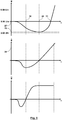
- a method of operating a laboratory centrifuge according to Fig. 1 to 3 is based on Fig. 4 with reference to the time courses of the angle, the angular velocity and the angular acceleration according to Fig. 5 explains:
- the product 6 is provided. This provision of the product 6 takes place in a half space 19, which is located in front of the rotor 2 and is separated by the plane of rotation of the rotor 2 from a half space 20 located behind the rotor 2.
- the product 6 is not introduced directly into the holder 4 or receptacle 5 of the rotor 2, but using a receiving body 21, which may also be a sample carrier, in a method step 22, at least one product 6 is introduced into one Thereafter, in a method step 23, the rotor is brought into an angular position, which forms a loading position.
- This loading order is, for example, the in Fig. 1 assumed position, which is a 6:00 o'clock position.
- the at least one product 6, preferably with the receiving body 21 is introduced through the feed opening 8 into the receptacle 5 via a suitable actuator or a handling device in a method step 24.
- a subsequent method step 25 the product 6 is fastened to the holder 4 of the rotor 2 formed by the receptacle 5.
- the coupling of one takes place in this method step Coupling portion of the receiving body 21 with a corresponding, formed by the holder 4 counter-coupling region of the rotor 2.
- a process step 26 then the rotor 2 of the drive unit 17 from the 6 o'clock position according to Fig. 1 , which here forms the feed or loading position 27, slowly transferred to a time 28 in a rest angle position 29.
- the rotor 2 is first accelerated up to a time 30 counterclockwise and subsequently braked so that it has at time 28 in the rest angle position 29 an angular velocity zero. It is possible that the rotor 2 remains in the rest angle position 29 for a period of time. Preferably, however, the angular velocity reverses immediately in the rest angle position 29.
- the rest angle position 29 is an angular position in the range between a 3: 00 o'clock position and 6: 00 o'clock position, wherein with a reduced exit or Ausfpdfne Trent the sample or substance, a higher viscosity of the Substance and a greater capillary action, a greater approximation of the rest angle position 29 can be made to the 3:00 o'clock position.
- the rotor 2 with product 6 held thereon is accelerated by the rest angle position 29 with the direction of rotation reversed, that is to say in the clockwise direction.
- the product 6 at a time 33, the 6:00 o'clock position whereby for the illustrated embodiment, a passing of the feed or loading position 27 takes place.
- the rotor 2 Due to the acceleration from the rest angle position 29, the rotor 2 has with the Product 6 when passing the 6 o'clock position already an angular velocity 34, which is greater than zero.
- "momentum can be fetched" with the provision of an energy level of the rotor 2 and the product 6 in FIG. 6: 00 o'clock position, which is greater than with an immediate start from the 6 o'clock position.
- the product 6 With further acceleration in a clockwise direction, the product 6 passes through the 9:00 o'clock position with increasing angular velocity in the 12:00 o'clock position, whereby depending on the drive power of the drive unit 17, the accelerating torque can be further increased in the following or this constant at a maximum moment remains with the resulting constant angular acceleration (cf. Fig. 5 ).
- the actual centrifuging takes place at the predetermined angular velocity or a predetermined angular velocity profile. If the centrifuging is completed, the rotor 2 decelerates.
- the control of the drive unit 17 takes place in such a way that in the reversed angular position there is an exactly predetermined angular velocity and thus a centrifugal acceleration which is greater than the gravitational acceleration.
- the braking of the rotor 2 with product 6 held thereon takes place in method step 37 at an angular speed of zero until a rest angle position is reached, which is set between the 3 o'clock position and the 9 o'clock position. Position is, preferably between the 6:00 o'clock position and the 9:00 o'clock position.
- the braking takes place in an angular range of less than 270 °.
- a reverse rotation of the rotor 2 takes place with it counterclockwise in a discharge or discharge position, which is preferably at the 6 o'clock position.
- the product 6 is released from the holder 4.
- the removal of the product 6 from the rotor 2 can take place, which preferably takes place through the removal opening 9.
- Fig. 6 schematically shows during start-up approximately in a 10:00 o'clock position the product 6 with the forces acting on the product (in which case a tangential acceleration due to the acceleration of the rotor 2 during start-up is omitted for the sake of simplicity).
- Fig. 6 It can be seen that without centrifugal force due to the weight 44, the sample 42 disposed in the container 41 of the product would be accelerated radially inwardly with a component of the weight 44, ie away from the bottom of the container 41 towards the lid.
- Fig. 7 and 8th show an alternative embodiment of a laboratory centrifuge 1, in which the drive unit 17 is not arranged coaxially with the axis of rotation 3. Rather, a drive or longitudinal axis 46 of the drive unit 17 and a drive shaft thereof is arranged parallel to and spaced from the axis of rotation 3. In this case, the drive unit 17 via a geared connection 47, for example.
- a traction drive 48, coupled to the rotor 2, wherein the geared connection 47 also ensures the offset of the drive or longitudinal axis 46 relative to the rotation axis 3, wherein additionally by means of the gear Connection 47 can be a translation or translation.
- the drive unit 17 is arranged with respect to the rotation axis 3 diametrically opposite to the receptacle 5 of the rotor 2 in the 6:00 o'clock position.
- the drive unit 17 is arranged in the upper half-plane of the rotor (9:00 o'clock position to 3:00 o'clock position), while in the feed or loading position 27 and / or the unloading position the receptacle 5 in the lower half-plane (3:00 o'clock position to 9:00 o'clock position) can be arranged, whereby the drive unit 17 does not hinder the supply and removal of the product 6 from the rotor 2 and result in improved space conditions.
- the support frame 15 as shown in the area of the receptacle 5 and before and behind this in the loading position 27 and / or unloading a gap or recess through which the receptacle 5 is accessible.
- Fig. 9 shows highly schematically a sensor 49, which detects an angular position of the rotor 2, and a sensor 50, which detects the angular velocity of the rotor 2.
- the measurement signals of the sensors 49, 50 are supplied to a control unit 51, which controls the drive unit 17 for carrying out the method explained above on this basis.
- the control unit 51 can communicate with further control units, for example also for the control of handling devices and loading and unloading devices for loading and unloading the product 6. It is also possible that only a rotation angle is detected by a sensor 49 and from this an angular velocity signal is derived.
- the drive unit 17 is already controlled in terms of angle of rotation, so that only the control unit 51 controls a predetermined rotation angle, and / or that an angle signal of the drive unit 17 is processed by the control unit 48.
- the sensor 49 for detecting the angular position of the rotor 2 (or correspondingly also a sensor 50 for detecting the angular velocity of the rotor 2) may also be formed as directly integrated into the drive unit 17 sensor, which, for example, anyway for the operation of the drive unit 17 is provided in this.
- the products 6 are, for example, blood tubes which may have typical dimensions of 13 ⁇ 75 mm, 13 ⁇ 100 mm or 16 ⁇ 100 mm.
- the acceleration takes place in such a way that with the achievement of a horizontal orientation of the product (9:00 o'clock position), a centrifugal acceleration greater than 2 ⁇ g has already been achieved.
- the braking in which case preferably in the reverse angular position, ie the 12:00 o'clock position, a centrifugal acceleration of at least 2 xg acts, which then over an angular range of 180 ° to 6:00 o'clock position is braked to the angular velocity zero.
- the gravitational field for the separation by centrifugation acts specifically in Direction of the bottom of the container 41.
- the removal of the container 41 horizontal course of the separation limits the risk of mixing during removal from the laboratory centrifuge 1 is at least reduced. Such a result would otherwise be achieved only by swinging bucket rotors, while the separation limit in fixed angle rotors is typically at an angle which is not perpendicular to the normal of the vessel bottom.
- the receiving body 21 is formed as a vessel holder, which may be fixedly mounted with the rotor 2 or may be interchangeable.
- An interchangeable vessel holder is intended for use as part of a linear or plate-shaped transport system, through which the vessel can be transported to further process steps.
- the drive unit 17 and the support frame 15 are mounted in a housing, not shown, which ensures safety. By damping elements between the drive 17, support frame 15 and / or housing, the transmission of vibrations to the housing is greatly reduced.
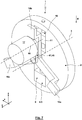
- Fig. 10 and 11 show a further embodiment of a rotor 2 with balancing device 10.
- the balancing mass 11 is in an edge-closed through hole 52nd arranged, which has a rectangular cross section here.
- the radially oriented boundaries of the passage recess 52 form two radially oriented parallel guides 53, in particular ribs 54, between which the balancing mass 11 is guided to change their distance from the axis of rotation 3.
- the leveling compound 11 may be formed in two or more parts.
- the balancing mass 11 has a radial axis of rotation 3 oriented through threaded hole 55 through which an actuating rod 56 extends.
- the actuating rod 56 has in the with the balancing mass 11 and the threaded bore 55 interacting axial region via an external thread not shown here.
- the actuating rod 56 is rotatable in its two end regions, but mounted axially fixed relative to the rotor 2.
- the actuating rod 56 projects with the radially outer end region out of the lateral surface of the rotor 2 with an actuating or engagement surface 57.
- a screwdriver a hexagon u.
- the actuating rod 56 are rotated, which in the manner of a spindle drive, the balancing mass is moved so that the distance of the balancing mass 11 of the rotation axis 3 changes, bringing the compensation a possible imbalance can take place.
- the receiving body 21 is formed like a block or cuboid.
- the receiving body 21 has a receptacle 58 into which the product 6 can be inserted from above.
- the receptacle 58 is a blind hole 59 introduced from above against the z-direction into the receiving body 21, into which a product 6 having a cylindrical lateral surface, for example a container or test tube, can be used, wherein preferably the product 6 is secured frictionally or exclusively by the gravitational acceleration and any acting centrifugal forces in the receptacle 58.
- the receiving body 21 has a coupling region 60, via which the receiving body 21 can be coupled to the rotor 2.
- the coupling region 60 has two partial coupling regions 61, 62:
- the partial coupling region 61 is here formed with two y-oriented grooves 63, which are arranged on opposite sides of the receiving body 21.
- the grooves 63 have a trapezoidal, outward expanding cross-section.
- the rotor 2 forms in the region of the through-passage 7 on opposite sides guides 64, in this case ribs 65, whose shape and position coincide with the shape and position of the grooves 63.
- the partial coupling region 62 serves. This is formed with a groove 66, which is on the underside of the receiving body 21 with extension in the x-direction, ie transverse to the axis of rotation 3. As in Fig. 14 can be seen, the wall of the rotor 2, which defines the through-hole 7 radially outward, via a recess 67 in which a pivot lever 68 is pivotally mounted about a pivot axis 69 which is oriented parallel y-axis.
- One end region of the pivoting lever 68 carries a locking element 70, while the other end region of the pivoting lever 68 is acted upon by a spring 71 such that, without rotation of the rotor 2, the pivoting lever 68 assumes a pivoting position in which the locking element 70 is displaced radially outwards in this way, that this does not interact with the receiving body 21.
- the receiving body 21 is arranged centrally in the through-hole 7, that is to say in accordance with the predetermined axial position, the groove 63 and the locking element 70 are in a common plane with the pivoting lever 68, which is oriented transversely to the axis of rotation 3.
- the rotor 2 On the side facing away from the locking element 70 side of the pivot lever 68 carries a mass 72. If in the predetermined axial position of the receiving body 21, the rotor 2 is set in rotation, acts on the mass 72, a centrifugal force, which leads to the spring 71 causes the locking element 70 enters the groove 63, whereby a positive locking with elimination of said axial degree of freedom is formed in the y direction. In this case, the pressing of the locking element 70 is increased in the groove 63 with increasing angular velocity of the rotor 2.
- the receiving body 21 has only one receptacle 58. It is understood that a plurality of receptacles 58 for several products 6 may be provided on a single receiving body 21.
- Both the balancing mass 11 and the receiving body 21 are secured against rotation about the rotation axis 3 with large contact surfaces. It is advantageous if the rotor 2 has flat end faces, from which in particular the receiving body 21 and the compensation mass 11 do not protrude parallel to the axis of rotation 3, since otherwise an increased air resistance would arise with increasing the power requirement for generating the rotational movement of the rotor. 2 It is possible that the leadership of the balancing mass 11 and / or the receiving body 21 takes place on the rotor 2 in the manner of a "dovetail guide". It is also possible that the recesses 7, 52, for example, by a centrifugally operated self-closing or manually closed cover plate, are closed during centrifugation to the outside.
- an additional rotor in particular a rotor disc can be accelerated simultaneously with the acceleration of the rotor 2 in an opposite direction of rotation to compensate for the overturning moment. This can lead to a spin compensation or compensation of the overturning moment independently of the acting acceleration. If the additional rotor has the same mass moment of inertia as the rotor 2, the additional rotor can be driven at the same angular velocity and acceleration. If an additional rotor is used with a different mass moment of inertia, a corresponding over or under reduction of the rotary movement must take place.
- a laboratory centrifuge 1 is on a preferably horizontal surface
- an assembly of the laboratory centrifuge 1 on a laboratory wall or on another vertical support wall of a furnishing article, wearer u. ⁇ . Whereby the rotation plane of the rotor 2 can be aligned parallel to the wall, whereby a particularly flat and space-saving design is possible.
- the rotor 2 is formed in a lightweight construction.
- this has advantages with regard to the aforementioned tilting moment, which becomes smaller with reduced mass or reduced mass moment of inertia.
- the required high accelerations with comparatively small drive torques of the drive unit 17 can be brought about.
- lightweight construction for example, light aluminum alloys, carbon fiber reinforced plastics, a combined plastic / metal construction can be used.
- weight-reducing material recesses continuous or non-continuous recesses, for example in the radial direction and / or parallel to the axis of rotation).
- a fixation of the rotor 2 in the loading and / or unloading position is desirable.
- a fixing holding torque can be applied to the rotor 2 by the drive unit 17, so that no additional fixing devices are required. It is also entirely possible, however, that a fixing of the rotor 2, the drive unit 17 and / or the geared connection 47 via a latching or locking device which manually and / or automatically via an actuator, which may be controlled by the control unit 51, operated and / or can be solved.
Landscapes
- Chemical & Material Sciences (AREA)
- Chemical Kinetics & Catalysis (AREA)
- Centrifugal Separators (AREA)
Claims (14)
- Procédé de fonctionnement d'une centrifugeuse de laboratoire (1) destiné à la centrifugation d'un produit (6), la centrifugeuse de laboratoire (1) présentant un rotor (2) qui tourne autour d'un axe de rotation (3) horizontal et sur lequel le produit (6) est retenu à distance de l'axe de rotation (6), dans lequela) à partir d'une position angulaire de repos (27) du produit (6) dans laquelle le produit (6) est disposé entre une position 3h00 et une position 9h00 et possède une vitesse angulaire nulle, le rotor (2) est accéléré de telle sorte que, lors de l'obtention pour la première fois de la position angulaire inverse du rotor (2) dans laquelle le produit (6) est disposé dans une position 12h00 heures, le rotor (2) a atteint une vitesse angulaire qui est élevée au point que l'accélération centrifuge agissant sur le produit (6) est plus élevée que l'accélération due à la gravité, et/oub) à partir d'une position angulaire inverse du produit (6) dans laquelle le produit (6) est disposé dans une position 12h00 et possède une vitesse angulaire qui est élevée au point que l'accélération centrifuge agissant sur le produit (6) est plus élevée que l'accélération due à la gravité jusqu'à l'obtention pour la première fois d'une position angulaire de repos du rotor (2) dans laquelle le produit (6) est disposé entre une position 3h00 et une position 9h00 heures, le rotor (2) est freiné à une vitesse angulaire nulle,caractérisé en ce quec) pendant l'accélération et/ou le freinage, le produit (6) passe par une position 6h00, et l'accélération s'effectue à partir de la position angulaire de repos (27) jusqu'à l'obtention pour la première fois de la position angulaire inverse et/ou le freinage s'effectue à partir de la position angulaire inverse jusqu'à l'obtention pour la première fois de la position angulaire de repos sur une plage angulaire entre 180° et 270°,d) dans lequel un chargement et déchargement du produit (6) vers et en provenance du rotor (2) s'effectuent dans une position de chargement et déchargement qui correspond à la position 6h00 etda) à la suite d'un chargement, le rotor (2) est, d'abord au moyen de l'entraînement, transféré avec un premier sens directionnel de rotation dans la position angulaire de repos (27) à partir de laquelle l'accélération s'effectue ensuite avec un deuxième sens directionnel de rotation inverse en direction de la position angulaire inverse, et/oudb) jusqu'à la position angulaire de repos pendant le freinage, une rotation du rotor (2) avec un premier sens directionnel de rotation s'effectue avec ensuite une rotation en arrière avec un deuxième sens directionnel de rotation opposé, à partir de la position angulaire de repos vers la position de déchargement.
- Procédé selon la revendication 1, caractérisé en ce que, dans la position angulaire inverse, la vitesse angulaire est élevée au point que l'accélération centrifuge agissant sur le produit (6) correspond au moins au double de l'accélération due à la gravité.
- Procédé selon l'une des revendications 1 à 2, caractérisé en ce que le produit (6) est automatiquementa) acheminé au rotor (2) et/oub) enlevé du rotor (2).
- Procédé selon la revendication 3, caractérisé en ce que, avec un mouvement avec le même sens directionnel de rotation, le produit (6) est automatiquementa) acheminé au rotor (2) etb) enlevé du rotor (2) après la centrifugation.
- Procédé selon l'une des revendications 1 à 4, caractérisé en ce que, par le biais d'un système de compensation (10), un balourd du rotor (2) qui dépend de la masse du produit (6) est réduit ou supprimé.
- Procédé selon l'une des revendications précédentes, caractérisé en ce que le produit (6) est fixé sur le rotor (2) par le biais d'un élément de retenue (4).
- Procédé selon la revendication 6, caractérisé en ce que l'élément de retenue (4) est formé avec un corps de logement qui contient un logement dans lequel le produit (6) est disposé, et qui constitue une zone de couplage par le biais de laquelle le corps de logement avec le produit (6) disposé dans le logement est fixé sur le rotor (2).
- Procédé selon l'une des revendications précédentes, caractérisé en ce qu'un angle de rotation du rotor (2) est détecté par le biais d'un capteur (46), et l'unité ou une unité d'entraînement (17) du rotor (2) est commandée ou régulée sur la base de l'angle de rotation détecté.
- Procédé selon l'une des revendications précédentes, caractérisé en ce que l'unité ou une unité d'entraînement (17) est commandée ou régulée sur la base de l'angle de rotation.
- Centrifugeuse de laboratoire (1) destinée à la centrifugation d'un produit (6), la centrifugeuse de laboratoire (1) présentant un rotor (2) qui tourne autour d'un axe de rotation (3) horizontal et sur lequel le produit (6) est retenu à distance de l'axe de rotation (3), caractérisée en ce qu'il y a une unité d'entraînement (117) qui peut être pilotée par le biais d'une unité de commande (48) pour la réalisation d'un procédé selon l'une des revendications 1 à 9.
- Centrifugeuse de laboratoire (1) selon la revendication 10, caractérisée en ce que le rotor (2) constitue un logement (5) pour le produit (6), une ouverture d'acheminement (8) du logement (5) étant constituée sur un côté du rotor (2), par le biais de laquelle un produit (6) peut être acheminé au logement (5), et une ouverture d'enlèvement (9) du logement (5) étant constituée sur l'autre côté du rotor (2), par le biais de laquelle le produit peut être enlevé du logement (5) après la centrifugation.
- Centrifugeuse de laboratoire (1) selon la revendication 10 ou 11, caractérisée en ce que le rotor (2) est entraîné par le biais d'un axe longitudinal ou axe d'entraînement (43) d'une unité d'entraînement (17) qui est disposée parallèlement à l'axe de rotation (3) du rotor (2) et à distance de cet axe, l'unité d'entraînement (17) étant disposée dans la direction circonférentielle autour de l'axe de rotation (3) de façon décalée par rapport au logement (5) ou à l'élément de retenue (4) pour le produit (6) dans une position angulaire de chargement (27) et ou une position angulaire de déchargement.
- Centrifugeuse de laboratoire (1) selon l'une des revendications 10 à 12, caractérisée en ce qu'il y a un capteur (46) pour la détection de l'angle de rotation du rotor (2), et en ce qu'il y a une unité de commande (48) qui est équipée d'une logique de commande qui commande ou régule l'unité ou une unité d'entraînement (17) du rotor (2) sur la base de l'angle de rotation détecté du rotor (2).
- Centrifugeuse de laboratoire (1) selon l'une des revendications 10 à 13, caractérisée en ce que l'unité ou une unité d'entraînement (17) présente une régulation à orientation de champ.
Priority Applications (3)
| Application Number | Priority Date | Filing Date | Title |
|---|---|---|---|
| EP15162405.3A EP3075454B1 (fr) | 2015-04-02 | 2015-04-02 | Centrifugeuse de laboratoire et son procédé de fonctionnement |
| CN201610412373.9A CN106111353B (zh) | 2015-04-02 | 2016-04-01 | 实验室离心机及其运行方法 |
| US15/088,647 US10245598B2 (en) | 2015-04-02 | 2016-04-01 | Laboratory centrifuge and method for operating the same with a reversed driving motion of the rotor during acceleration and deceleration |
Applications Claiming Priority (1)
| Application Number | Priority Date | Filing Date | Title |
|---|---|---|---|
| EP15162405.3A EP3075454B1 (fr) | 2015-04-02 | 2015-04-02 | Centrifugeuse de laboratoire et son procédé de fonctionnement |
Publications (2)
| Publication Number | Publication Date |
|---|---|
| EP3075454A1 EP3075454A1 (fr) | 2016-10-05 |
| EP3075454B1 true EP3075454B1 (fr) | 2018-05-09 |
Family
ID=52814853
Family Applications (1)
| Application Number | Title | Priority Date | Filing Date |
|---|---|---|---|
| EP15162405.3A Active EP3075454B1 (fr) | 2015-04-02 | 2015-04-02 | Centrifugeuse de laboratoire et son procédé de fonctionnement |
Country Status (3)
| Country | Link |
|---|---|
| US (1) | US10245598B2 (fr) |
| EP (1) | EP3075454B1 (fr) |
| CN (1) | CN106111353B (fr) |
Families Citing this family (3)
| Publication number | Priority date | Publication date | Assignee | Title |
|---|---|---|---|---|
| EP3421134B1 (fr) * | 2017-06-27 | 2020-09-30 | Tecan Trading Ag | Unité de traitement centrifuge |
| CN112044608B (zh) * | 2020-10-12 | 2024-04-16 | 武汉成名仪器有限公司 | 实验室离心机转子平衡锁定装置、离心机转子和离心机 |
| CN112791862B (zh) * | 2021-01-25 | 2024-07-23 | 伯特利(山东)工业设备有限公司 | 一种离心机用在线动平衡装置 |
Family Cites Families (9)
| Publication number | Priority date | Publication date | Assignee | Title |
|---|---|---|---|---|
| US2821339A (en) | 1956-09-10 | 1958-01-28 | Wyble Engineering Dev Corp | Centrifuge |
| US4827197A (en) * | 1987-05-22 | 1989-05-02 | Beckman Instruments, Inc. | Method and apparatus for overspeed protection for high speed centrifuges |
| CN1415422A (zh) * | 1992-08-07 | 2003-05-07 | 邓延忠 | 转筒式离心分离机 |
| FR2858251B1 (fr) * | 2003-07-29 | 2005-10-28 | Diagyr | Procede pour equilibrer un plateau rotatif d'une centrifugeuse et centrifugeuse mettant en oeuvre le procede |
| US7803101B2 (en) * | 2007-01-30 | 2010-09-28 | Ortho-Clinical Diagnostics, Inc. | Random access multi-disc centrifuge |
| US9039992B2 (en) * | 2011-06-06 | 2015-05-26 | Abbott Laboratories | Apparatus for closed tube sampling and open tube sampling for automated clinical analyzers |
| KR101252260B1 (ko) * | 2011-12-12 | 2013-04-08 | 포항공과대학교 산학협력단 | 디스크형 미세 유체 시스템 및 혈구의 변형도 측정 방법 |
| DE102012201717A1 (de) * | 2012-02-06 | 2013-08-08 | AusBio Laboratories Co, Ltd. | Probenträger-Zentrifuge |
| EP2835178B1 (fr) * | 2013-08-06 | 2017-04-12 | Yantai AusBio Laboratories Co., Ltd. | Centrifugeuse et procédé pour la centrifugation d'une unité de récipient de réaction |
-
2015
- 2015-04-02 EP EP15162405.3A patent/EP3075454B1/fr active Active
-
2016
- 2016-04-01 CN CN201610412373.9A patent/CN106111353B/zh active Active
- 2016-04-01 US US15/088,647 patent/US10245598B2/en active Active
Non-Patent Citations (1)
| Title |
|---|
| None * |
Also Published As
| Publication number | Publication date |
|---|---|
| EP3075454A1 (fr) | 2016-10-05 |
| US20160288141A1 (en) | 2016-10-06 |
| US10245598B2 (en) | 2019-04-02 |
| CN106111353A (zh) | 2016-11-16 |
| CN106111353B (zh) | 2019-08-06 |
Similar Documents
| Publication | Publication Date | Title |
|---|---|---|
| DE102010003223B4 (de) | Vorrichtung zum Einsetzen in einen Rotor einer Zentrifuge, Zentrifuge und Verfahren zum fluidischen Koppeln von Kavitäten | |
| DE69215660T2 (de) | Selbstauswuchtendes gerät und verfahren für eine zentrifuge | |
| DE60223704T2 (de) | Vorrichtung zur extraktion von nukleinsäuren | |
| DE202013012306U1 (de) | Probenträger-Zentrifuge | |
| EP3075454B1 (fr) | Centrifugeuse de laboratoire et son procédé de fonctionnement | |
| EP1767275A1 (fr) | Rotor et support de godets pour centrifugeuse à godets pivotants | |
| DE102012009987A1 (de) | Laborkugelmühle | |
| EP1979096B1 (fr) | Systeme microfluidique et systeme modulaire de "laboratoire sur puce" | |
| DE102009048918A1 (de) | Vorrichtung zum Mischen einer Flüssigkeitsprobe | |
| EP1987362A2 (fr) | Dispositif et procédé de traitement ou d'épuration d'échantillons, notamment d'acides nucléiques | |
| EP1919625B1 (fr) | Dispositif et procede de separation de particules magnetiques d'un liquide | |
| DE102015103752A1 (de) | Zentrifuge | |
| EP1075324B1 (fr) | Procede et dispositif pour melanger et laver des liquides et/ou des solides, ainsi que pour laver des recipients | |
| DE102012009984A1 (de) | Laborkugelmühle | |
| DE102012009982A1 (de) | Laborkugelmühle | |
| DE102012009985A1 (de) | Laborkugelmühle | |
| DE102008054089A1 (de) | Zentrifuge | |
| WO2018011085A1 (fr) | Manipulation de liquides en utilisant un module fluidique présentant un plan fluidique incliné par rapport à un plan de rotation | |
| WO2008043463A1 (fr) | Dispositif et procédé de fabrication d'une station pour formuler des formulations de substances | |
| EP2771122A1 (fr) | Procédé de chargement automatique d'une centrifugeuse comprenant des contenants d'échantillons | |
| DE102022207743A1 (de) | Unwuchtmesseinrichtung, Bearbeitungseinrichtung, sowie Verfahren zur Bearbeitung eines Werkstücks | |
| DE102008042971A1 (de) | Zentrifuge mit Magneteinrichtung | |
| EP4306220B1 (fr) | Rotor de centrifugeuse et centrifugeuse | |
| DE102013207232A1 (de) | Sedimentationsvorrichtung, insbesondere für Partikel, sowie Kartusche | |
| DE2932849C2 (de) | Zentrifuge |
Legal Events
| Date | Code | Title | Description |
|---|---|---|---|
| PUAI | Public reference made under article 153(3) epc to a published international application that has entered the european phase |
Free format text: ORIGINAL CODE: 0009012 |
|
| 17P | Request for examination filed |
Effective date: 20160121 |
|
| AK | Designated contracting states |
Kind code of ref document: A1 Designated state(s): AL AT BE BG CH CY CZ DE DK EE ES FI FR GB GR HR HU IE IS IT LI LT LU LV MC MK MT NL NO PL PT RO RS SE SI SK SM TR |
|
| AX | Request for extension of the european patent |
Extension state: BA ME |
|
| GRAP | Despatch of communication of intention to grant a patent |
Free format text: ORIGINAL CODE: EPIDOSNIGR1 |
|
| STAA | Information on the status of an ep patent application or granted ep patent |
Free format text: STATUS: GRANT OF PATENT IS INTENDED |
|
| INTG | Intention to grant announced |
Effective date: 20180213 |
|
| GRAS | Grant fee paid |
Free format text: ORIGINAL CODE: EPIDOSNIGR3 |
|
| GRAA | (expected) grant |
Free format text: ORIGINAL CODE: 0009210 |
|
| STAA | Information on the status of an ep patent application or granted ep patent |
Free format text: STATUS: THE PATENT HAS BEEN GRANTED |
|
| AK | Designated contracting states |
Kind code of ref document: B1 Designated state(s): AL AT BE BG CH CY CZ DE DK EE ES FI FR GB GR HR HU IE IS IT LI LT LU LV MC MK MT NL NO PL PT RO RS SE SI SK SM TR |
|
| REG | Reference to a national code |
Ref country code: GB Ref legal event code: FG4D Free format text: NOT ENGLISH |
|
| REG | Reference to a national code |
Ref country code: CH Ref legal event code: EP Ref country code: AT Ref legal event code: REF Ref document number: 997091 Country of ref document: AT Kind code of ref document: T Effective date: 20180515 |
|
| REG | Reference to a national code |
Ref country code: IE Ref legal event code: FG4D Free format text: LANGUAGE OF EP DOCUMENT: GERMAN |
|
| REG | Reference to a national code |
Ref country code: DE Ref legal event code: R096 Ref document number: 502015004173 Country of ref document: DE |
|
| REG | Reference to a national code |
Ref country code: NL Ref legal event code: MP Effective date: 20180509 |
|
| REG | Reference to a national code |
Ref country code: LT Ref legal event code: MG4D |
|
| PG25 | Lapsed in a contracting state [announced via postgrant information from national office to epo] |
Ref country code: ES Free format text: LAPSE BECAUSE OF FAILURE TO SUBMIT A TRANSLATION OF THE DESCRIPTION OR TO PAY THE FEE WITHIN THE PRESCRIBED TIME-LIMIT Effective date: 20180509 Ref country code: SE Free format text: LAPSE BECAUSE OF FAILURE TO SUBMIT A TRANSLATION OF THE DESCRIPTION OR TO PAY THE FEE WITHIN THE PRESCRIBED TIME-LIMIT Effective date: 20180509 Ref country code: LT Free format text: LAPSE BECAUSE OF FAILURE TO SUBMIT A TRANSLATION OF THE DESCRIPTION OR TO PAY THE FEE WITHIN THE PRESCRIBED TIME-LIMIT Effective date: 20180509 Ref country code: NO Free format text: LAPSE BECAUSE OF FAILURE TO SUBMIT A TRANSLATION OF THE DESCRIPTION OR TO PAY THE FEE WITHIN THE PRESCRIBED TIME-LIMIT Effective date: 20180809 Ref country code: FI Free format text: LAPSE BECAUSE OF FAILURE TO SUBMIT A TRANSLATION OF THE DESCRIPTION OR TO PAY THE FEE WITHIN THE PRESCRIBED TIME-LIMIT Effective date: 20180509 Ref country code: BG Free format text: LAPSE BECAUSE OF FAILURE TO SUBMIT A TRANSLATION OF THE DESCRIPTION OR TO PAY THE FEE WITHIN THE PRESCRIBED TIME-LIMIT Effective date: 20180809 |
|
| PG25 | Lapsed in a contracting state [announced via postgrant information from national office to epo] |
Ref country code: RS Free format text: LAPSE BECAUSE OF FAILURE TO SUBMIT A TRANSLATION OF THE DESCRIPTION OR TO PAY THE FEE WITHIN THE PRESCRIBED TIME-LIMIT Effective date: 20180509 Ref country code: GR Free format text: LAPSE BECAUSE OF FAILURE TO SUBMIT A TRANSLATION OF THE DESCRIPTION OR TO PAY THE FEE WITHIN THE PRESCRIBED TIME-LIMIT Effective date: 20180810 Ref country code: LV Free format text: LAPSE BECAUSE OF FAILURE TO SUBMIT A TRANSLATION OF THE DESCRIPTION OR TO PAY THE FEE WITHIN THE PRESCRIBED TIME-LIMIT Effective date: 20180509 Ref country code: NL Free format text: LAPSE BECAUSE OF FAILURE TO SUBMIT A TRANSLATION OF THE DESCRIPTION OR TO PAY THE FEE WITHIN THE PRESCRIBED TIME-LIMIT Effective date: 20180509 Ref country code: HR Free format text: LAPSE BECAUSE OF FAILURE TO SUBMIT A TRANSLATION OF THE DESCRIPTION OR TO PAY THE FEE WITHIN THE PRESCRIBED TIME-LIMIT Effective date: 20180509 |
|
| PG25 | Lapsed in a contracting state [announced via postgrant information from national office to epo] |
Ref country code: CZ Free format text: LAPSE BECAUSE OF FAILURE TO SUBMIT A TRANSLATION OF THE DESCRIPTION OR TO PAY THE FEE WITHIN THE PRESCRIBED TIME-LIMIT Effective date: 20180509 Ref country code: SK Free format text: LAPSE BECAUSE OF FAILURE TO SUBMIT A TRANSLATION OF THE DESCRIPTION OR TO PAY THE FEE WITHIN THE PRESCRIBED TIME-LIMIT Effective date: 20180509 Ref country code: PL Free format text: LAPSE BECAUSE OF FAILURE TO SUBMIT A TRANSLATION OF THE DESCRIPTION OR TO PAY THE FEE WITHIN THE PRESCRIBED TIME-LIMIT Effective date: 20180509 Ref country code: DK Free format text: LAPSE BECAUSE OF FAILURE TO SUBMIT A TRANSLATION OF THE DESCRIPTION OR TO PAY THE FEE WITHIN THE PRESCRIBED TIME-LIMIT Effective date: 20180509 Ref country code: EE Free format text: LAPSE BECAUSE OF FAILURE TO SUBMIT A TRANSLATION OF THE DESCRIPTION OR TO PAY THE FEE WITHIN THE PRESCRIBED TIME-LIMIT Effective date: 20180509 Ref country code: RO Free format text: LAPSE BECAUSE OF FAILURE TO SUBMIT A TRANSLATION OF THE DESCRIPTION OR TO PAY THE FEE WITHIN THE PRESCRIBED TIME-LIMIT Effective date: 20180509 |
|
| REG | Reference to a national code |
Ref country code: DE Ref legal event code: R097 Ref document number: 502015004173 Country of ref document: DE |
|
| PG25 | Lapsed in a contracting state [announced via postgrant information from national office to epo] |
Ref country code: IT Free format text: LAPSE BECAUSE OF FAILURE TO SUBMIT A TRANSLATION OF THE DESCRIPTION OR TO PAY THE FEE WITHIN THE PRESCRIBED TIME-LIMIT Effective date: 20180509 Ref country code: SM Free format text: LAPSE BECAUSE OF FAILURE TO SUBMIT A TRANSLATION OF THE DESCRIPTION OR TO PAY THE FEE WITHIN THE PRESCRIBED TIME-LIMIT Effective date: 20180509 |
|
| PLBE | No opposition filed within time limit |
Free format text: ORIGINAL CODE: 0009261 |
|
| STAA | Information on the status of an ep patent application or granted ep patent |
Free format text: STATUS: NO OPPOSITION FILED WITHIN TIME LIMIT |
|
| 26N | No opposition filed |
Effective date: 20190212 |
|
| PG25 | Lapsed in a contracting state [announced via postgrant information from national office to epo] |
Ref country code: SI Free format text: LAPSE BECAUSE OF FAILURE TO SUBMIT A TRANSLATION OF THE DESCRIPTION OR TO PAY THE FEE WITHIN THE PRESCRIBED TIME-LIMIT Effective date: 20180509 |
|
| PG25 | Lapsed in a contracting state [announced via postgrant information from national office to epo] |
Ref country code: AL Free format text: LAPSE BECAUSE OF FAILURE TO SUBMIT A TRANSLATION OF THE DESCRIPTION OR TO PAY THE FEE WITHIN THE PRESCRIBED TIME-LIMIT Effective date: 20180509 |
|
| REG | Reference to a national code |
Ref country code: CH Ref legal event code: PL |
|
| REG | Reference to a national code |
Ref country code: BE Ref legal event code: MM Effective date: 20190430 |
|
| PG25 | Lapsed in a contracting state [announced via postgrant information from national office to epo] |
Ref country code: LU Free format text: LAPSE BECAUSE OF NON-PAYMENT OF DUE FEES Effective date: 20190402 Ref country code: MC Free format text: LAPSE BECAUSE OF FAILURE TO SUBMIT A TRANSLATION OF THE DESCRIPTION OR TO PAY THE FEE WITHIN THE PRESCRIBED TIME-LIMIT Effective date: 20180509 |
|
| PG25 | Lapsed in a contracting state [announced via postgrant information from national office to epo] |
Ref country code: LI Free format text: LAPSE BECAUSE OF NON-PAYMENT OF DUE FEES Effective date: 20190430 Ref country code: CH Free format text: LAPSE BECAUSE OF NON-PAYMENT OF DUE FEES Effective date: 20190430 |
|
| PG25 | Lapsed in a contracting state [announced via postgrant information from national office to epo] |
Ref country code: BE Free format text: LAPSE BECAUSE OF NON-PAYMENT OF DUE FEES Effective date: 20190430 |
|
| PG25 | Lapsed in a contracting state [announced via postgrant information from national office to epo] |
Ref country code: TR Free format text: LAPSE BECAUSE OF FAILURE TO SUBMIT A TRANSLATION OF THE DESCRIPTION OR TO PAY THE FEE WITHIN THE PRESCRIBED TIME-LIMIT Effective date: 20180509 |
|
| PG25 | Lapsed in a contracting state [announced via postgrant information from national office to epo] |
Ref country code: IE Free format text: LAPSE BECAUSE OF NON-PAYMENT OF DUE FEES Effective date: 20190402 |
|
| PG25 | Lapsed in a contracting state [announced via postgrant information from national office to epo] |
Ref country code: PT Free format text: LAPSE BECAUSE OF FAILURE TO SUBMIT A TRANSLATION OF THE DESCRIPTION OR TO PAY THE FEE WITHIN THE PRESCRIBED TIME-LIMIT Effective date: 20180910 |
|
| PG25 | Lapsed in a contracting state [announced via postgrant information from national office to epo] |
Ref country code: CY Free format text: LAPSE BECAUSE OF FAILURE TO SUBMIT A TRANSLATION OF THE DESCRIPTION OR TO PAY THE FEE WITHIN THE PRESCRIBED TIME-LIMIT Effective date: 20180509 |
|
| REG | Reference to a national code |
Ref country code: AT Ref legal event code: MM01 Ref document number: 997091 Country of ref document: AT Kind code of ref document: T Effective date: 20200402 |
|
| PG25 | Lapsed in a contracting state [announced via postgrant information from national office to epo] |
Ref country code: IS Free format text: LAPSE BECAUSE OF FAILURE TO SUBMIT A TRANSLATION OF THE DESCRIPTION OR TO PAY THE FEE WITHIN THE PRESCRIBED TIME-LIMIT Effective date: 20180909 |
|
| PG25 | Lapsed in a contracting state [announced via postgrant information from national office to epo] |
Ref country code: HU Free format text: LAPSE BECAUSE OF FAILURE TO SUBMIT A TRANSLATION OF THE DESCRIPTION OR TO PAY THE FEE WITHIN THE PRESCRIBED TIME-LIMIT; INVALID AB INITIO Effective date: 20150402 Ref country code: MT Free format text: LAPSE BECAUSE OF FAILURE TO SUBMIT A TRANSLATION OF THE DESCRIPTION OR TO PAY THE FEE WITHIN THE PRESCRIBED TIME-LIMIT Effective date: 20180509 |
|
| PG25 | Lapsed in a contracting state [announced via postgrant information from national office to epo] |
Ref country code: AT Free format text: LAPSE BECAUSE OF NON-PAYMENT OF DUE FEES Effective date: 20200402 |
|
| PG25 | Lapsed in a contracting state [announced via postgrant information from national office to epo] |
Ref country code: MK Free format text: LAPSE BECAUSE OF FAILURE TO SUBMIT A TRANSLATION OF THE DESCRIPTION OR TO PAY THE FEE WITHIN THE PRESCRIBED TIME-LIMIT Effective date: 20180509 |
|
| P01 | Opt-out of the competence of the unified patent court (upc) registered |
Effective date: 20230529 |
|
| PGFP | Annual fee paid to national office [announced via postgrant information from national office to epo] |
Ref country code: DE Payment date: 20250212 Year of fee payment: 11 |
|
| PGFP | Annual fee paid to national office [announced via postgrant information from national office to epo] |
Ref country code: FR Payment date: 20250422 Year of fee payment: 11 |
|
| PGFP | Annual fee paid to national office [announced via postgrant information from national office to epo] |
Ref country code: GB Payment date: 20260324 Year of fee payment: 12 |