EP3075657B1 - Nacelle multifonction pour un avion - Google Patents
Nacelle multifonction pour un avion Download PDFInfo
- Publication number
- EP3075657B1 EP3075657B1 EP16162160.2A EP16162160A EP3075657B1 EP 3075657 B1 EP3075657 B1 EP 3075657B1 EP 16162160 A EP16162160 A EP 16162160A EP 3075657 B1 EP3075657 B1 EP 3075657B1
- Authority
- EP
- European Patent Office
- Prior art keywords
- pod
- aircraft
- fuel
- receiving
- area
- Prior art date
- Legal status (The legal status is an assumption and is not a legal conclusion. Google has not performed a legal analysis and makes no representation as to the accuracy of the status listed.)
- Active
Links
Images


Classifications
-
- B—PERFORMING OPERATIONS; TRANSPORTING
- B64—AIRCRAFT; AVIATION; COSMONAUTICS
- B64D—EQUIPMENT FOR FITTING IN OR TO AIRCRAFT; FLIGHT SUITS; PARACHUTES; ARRANGEMENT OR MOUNTING OF POWER PLANTS OR PROPULSION TRANSMISSIONS IN AIRCRAFT
- B64D1/00—Dropping, ejecting, releasing or receiving articles, liquids, or the like, in flight
- B64D1/02—Dropping, ejecting, or releasing articles
- B64D1/08—Dropping, ejecting, or releasing articles the articles being load-carrying devices
-
- B—PERFORMING OPERATIONS; TRANSPORTING
- B64—AIRCRAFT; AVIATION; COSMONAUTICS
- B64D—EQUIPMENT FOR FITTING IN OR TO AIRCRAFT; FLIGHT SUITS; PARACHUTES; ARRANGEMENT OR MOUNTING OF POWER PLANTS OR PROPULSION TRANSMISSIONS IN AIRCRAFT
- B64D1/00—Dropping, ejecting, releasing or receiving articles, liquids, or the like, in flight
- B64D1/02—Dropping, ejecting, or releasing articles
- B64D1/04—Dropping, ejecting, or releasing articles the articles being explosive, e.g. bombs
-
- B—PERFORMING OPERATIONS; TRANSPORTING
- B64—AIRCRAFT; AVIATION; COSMONAUTICS
- B64D—EQUIPMENT FOR FITTING IN OR TO AIRCRAFT; FLIGHT SUITS; PARACHUTES; ARRANGEMENT OR MOUNTING OF POWER PLANTS OR PROPULSION TRANSMISSIONS IN AIRCRAFT
- B64D37/00—Arrangements in connection with fuel supply for power plant
- B64D37/02—Tanks
- B64D37/06—Constructional adaptations thereof
- B64D37/12—Constructional adaptations thereof jettisonable
-
- B—PERFORMING OPERATIONS; TRANSPORTING
- B64—AIRCRAFT; AVIATION; COSMONAUTICS
- B64D—EQUIPMENT FOR FITTING IN OR TO AIRCRAFT; FLIGHT SUITS; PARACHUTES; ARRANGEMENT OR MOUNTING OF POWER PLANTS OR PROPULSION TRANSMISSIONS IN AIRCRAFT
- B64D7/00—Arrangement of military equipment, e.g. armaments, armament accessories or military shielding, in aircraft; Adaptations of armament mountings for aircraft
-
- F—MECHANICAL ENGINEERING; LIGHTING; HEATING; WEAPONS; BLASTING
- F41—WEAPONS
- F41F—APPARATUS FOR LAUNCHING PROJECTILES OR MISSILES FROM BARRELS, e.g. CANNONS; LAUNCHERS FOR ROCKETS OR TORPEDOES; HARPOON GUNS
- F41F3/00—Rocket or torpedo launchers
- F41F3/04—Rocket or torpedo launchers for rockets
- F41F3/06—Rocket or torpedo launchers for rockets from aircraft
-
- F—MECHANICAL ENGINEERING; LIGHTING; HEATING; WEAPONS; BLASTING
- F41—WEAPONS
- F41F—APPARATUS FOR LAUNCHING PROJECTILES OR MISSILES FROM BARRELS, e.g. CANNONS; LAUNCHERS FOR ROCKETS OR TORPEDOES; HARPOON GUNS
- F41F3/00—Rocket or torpedo launchers
- F41F3/04—Rocket or torpedo launchers for rockets
- F41F3/052—Means for securing the rocket in the launching apparatus
-
- F—MECHANICAL ENGINEERING; LIGHTING; HEATING; WEAPONS; BLASTING
- F41—WEAPONS
- F41F—APPARATUS FOR LAUNCHING PROJECTILES OR MISSILES FROM BARRELS, e.g. CANNONS; LAUNCHERS FOR ROCKETS OR TORPEDOES; HARPOON GUNS
- F41F3/00—Rocket or torpedo launchers
- F41F3/04—Rocket or torpedo launchers for rockets
- F41F3/06—Rocket or torpedo launchers for rockets from aircraft
- F41F3/065—Rocket pods, i.e. detachable containers for launching a plurality of rockets
-
- F—MECHANICAL ENGINEERING; LIGHTING; HEATING; WEAPONS; BLASTING
- F41—WEAPONS
- F41F—APPARATUS FOR LAUNCHING PROJECTILES OR MISSILES FROM BARRELS, e.g. CANNONS; LAUNCHERS FOR ROCKETS OR TORPEDOES; HARPOON GUNS
- F41F5/00—Launching-apparatus for gravity-propelled missiles or projectiles
Definitions
- Various embodiments generally relate to an aircraft having a multifunction pod.
- GB784429 shows such a multi-function pod divided into three areas and can accommodate different equipment, or fuel.
- Modern aircraft in particular combat aircraft, usually have only a limited number of external load carriers for attachment of weapons or tank containers, so-called pods on.
- To increase the range of a combat aircraft for example, additional tank containers, so-called discharge tanks are necessary.
- discharge tanks When using discharge tanks is therefore only a reduced number of external load carriers for the loading of the aircraft with other loads, such as weapons available.
- the aircraft can thus carry fewer loads, or the range of the aircraft is limited to the range that would be achieved by the use of the tank itself arranged in the tank.
- the task is solved by an airplane with a multifunction pod.
- the multifunction pod has at least two separate areas. At least a first portion of the pod is intended to receive fuel.
- a second area of the pod has at least one Receiving device for releasably attaching at least one further load.
- the further load is releasably attachable to the receiving device via a loading opening on the side of the pod facing away from the aircraft.
- the invention is based on the idea of providing an aircraft with a multi-function pod which both has an area for receiving fuel and also has at least one second or further area for detachable attachment of another load.
- the multi-function pod (or pod) therefore has several functions, on the one hand, the function as an external tank container and further as a receptacle for other releasably mounted loads. This increases the amount of fuel available to the aircraft. At the same time, the number of available external load carriers is maintained or even increased by the cradle available in the pod.
- a multi-function pod or pod is understood to mean a receptacle which can be detachably fastened to an aircraft, for example to the underside of the fuselage or to the underside of the wings.
- Such pods are attached, for example, to the outer load carriers of the aircraft and can be detached from the aircraft during the flight.
- these are referred to, for example, as a dump tank.
- the pod has a, on the side facing away from the aircraft, loading opening. Facing away from the aircraft is the side which, when the pod is mounted on the underside of the fuselage or the wing, faces away from the aircraft, here consequently on the underside of the pod.
- the loading opening on the side facing away from the aircraft can also be on the wing.
- the loading opening may then be directed downwards, for example for the release of a load mounted in the second area, so that the load can be dropped.
- different types of loads can be variably attached in the second area via the receiving device.
- different types and numbers of loads can be detachably attached via the receiving device.
- at least one outer load carrier or comparable load carrier or carrier can be attached to the receiving device.
- a plurality of, for example two or more outer load carriers or comparable load carriers for receiving a plurality of further loads may be arranged parallel and / or serially in the second area.
- the further load is at least one container for receiving fuel.
- a container for receiving fuel can be attached.
- the receiving device has an adapter for removing fuel from the container to the aircraft or for filling the container with fuel from the aircraft via an external refueling device.
- the receiving device can be provided for example with an outer load carrier, which has an adapter via which a fuel connection between the tank container and the aircraft can be made.
- the further load is at least one rocket or at least one bomb.
- a rocket is understood to be a guided missile.
- the rockets may be self-directed fire and forget missiles, remote-controlled missiles or semi-automatic missiles.
- a bomb is, for example, an unguided, wrong bomb or a so-called precision-bomb (smart bomb) to understand.
- the rockets are arranged to drop a short distance after release from the pod, preferably at least to the extent that they have left the loading area of the pod, and are fired only after leaving the pod and flying toward the destination. This has the advantage that the defense or attack possibilities of the aircraft can be increased by the further missiles or bombs.
- the accommodation of rockets or bombs in the pod has the advantage that it is not apparent from the outside whether and how the aircraft is armed, or how the range increase represents.
- the receiving device has at least one discharge device for one or more missiles.
- the at least one discharge device for example a HDERU (Heavy Duty Ejector Release Unit) or a comparable holding device, one or more Missiles are releasably secured, which can be released, for example, when reaching the target area.
- HDERU Heavy Duty Ejector Release Unit
- the at least one discharge device is preferably variably attachable to the receiving device. This has the advantage that, for example, the position of the discharge device in the longitudinal direction or transverse direction of the pod can be changed to match the respective load to be attached or the number of loads.
- the receiving device has at least one discharge device for one or more bombs.
- the at least one discharge device for example an HDERU (Heavy Duty Ejector Release Unit)
- one or more bombs can be detachably fastened, which can be released, for example, when the target area is reached.
- the at least one discharge device or holding device is preferably variably attachable to the receiving device. This has the advantage that, for example, the position and / or the number of ejection device in the longitudinal or transverse direction of the pod, to match the respective load to be attached or the number of loads or bombs, can be changed.
- the receiving device preferably has at least one adapter for controlling the ejection of the rockets or bombs via the aircraft.
- the cradle has at least one adapter, which is preferably connected to a release device, for example in the cockpit of the aircraft and can be transmitted via the signals to the discharge device, or can be transmitted from this, for example, to the cockpit.
- a signal can be transmitted to the discharge device via the adapter, so that the discharge device releases a rocket or bomb.
- a plurality of rockets and / or bombs are detachably attachable to the receiving device in parallel and / or one behind the other.
- a plurality of ejection devices for example HDERUs
- HDERUs can be arranged on the receiving device.
- two or more HDERUs can be arranged serially, ie in the longitudinal direction of the pod, behind one another within the loading area.
- two or more HDERUs can be arranged side by side on the receiving device.
- two HDERUs may be arranged in parallel for receiving, for example, two smaller missiles or bombs, and serially a single HDERU for receiving a larger missile or bomb.
- the Number or arrangement is limited only by the size of the loading area of the pod.
- the further load is at least one sensor device.
- the further load is a sensor device for reconnaissance and / or monitoring of an aviation area or a territory.
- the additional load can also be a communication module, for example for communication of the aircraft with other aircraft.
- the sensor device can also have a further communication device. This has the advantage that the aircraft via the pod in addition to the carriage of fuel can have other skills such as reconnaissance and / or surveillance. Moreover, this has the advantage that it is not recognizable from the outside or is very difficult to see whether a flight mission is performed with a sensor or not.
- the receiving device preferably has at least one adapter for communicating the aircraft with the sensor device.
- the receiving device In order to exchange data with the sensor device, ie in the direction from the aircraft to the sensor device or from the sensor device to the aircraft, the receiving device has an adapter which can be connected or coupled to the sensor device.
- the adapter may, for example, enable a wired and / or wireless data exchange between the sensor device and the aircraft.
- the receiving device is provided with a socket into which a plug of a cable connected to the sensor device can be coupled.
- the socket of the recording device is, for example, with the aircraft via, for example, another wired and / or also wireless connection connected. This has the advantage that in addition to the transport of fuel and "stupid" loads on the pod can also be transported loads that have a data exchange with or by plane.
- the pod has at least one further area for receiving fuel.
- the pod preferably has at least one or more further areas in which fuel can be taken up. This has the advantage that the amount of fuel carried in the pod is increased.
- the areas of the pod are arranged to receive fuel in the front and rear of the pod.
- the front and the rear of the pod are provided as a fuel area.
- the front and rear regions of a pod have a conically tapering shape, wherein the intermediate region has, at least partially or for the most part, an outer contour that is as constant as possible.
- the loading area is provided, for example, in the area with a contour that is as constant as possible.
- the area is provided with a tapered shape or with a non-constant outer shape for receiving fuel, since the shape of the pod in the area for receiving fuel is almost negligible.
- a loading area with a consistent shape is an advantage. This has the advantage that almost the entire loading area can be variably used for taking up loads. Next, this has the advantage that in addition to the carriage of one or several other loads, the available volume of the pod for the further absorption of fuel can be optimally utilized. In addition, there is the advantage that regardless of the load in the load range of the pod, the outer geometry of the pod is always the same. This also facilitates the aircraft control by the flight control system of the aircraft. In order to achieve a load distribution of the pod that is as constant as possible, the areas for receiving fuel can be distributed as neutral as possible, as far as possible.
- the areas for receiving fuel in the front area and in the rear area of the pod can be as equal as possible.
- a pumping of fuel for load balancing can thus be avoided at least within the pod itself.
- it can be advantageous for the load balance of the entire aircraft if fuel can be pumped between the available tank containers, internally and externally. For example, fuel from the aircraft's own tank can be pumped into the tank area of the pod for load balancing or vice versa.
- the area for receiving the further load is arranged according to the invention between the areas for receiving fuel.
- the fuel receiving area is divided into two or more subregions or segments.
- the area for receiving the further load is arranged, for example, at least partially between the areas for the fuel.
- the front and rear of the pod are considered as Provided fuel area and an intermediate area is provided as a loading area for receiving a further load.
- the areas for the fuel may also extend at least partially into the loading area. This has the advantage that the available volume of the pod can be optimally utilized.
- the areas for receiving fuel, on the side of the pod facing the aircraft at least partially extend into the second area.
- the multi-function pod can, for example, have additional areas for receiving fuel in the area of the receiving device. These further tank areas are arranged, for example, above the second area, ie the loading area.
- the loading area can be fitted on the underside of the loading opening.
- the first area for receiving fuel is connected, for example, directly to the other area for receiving fuel.
- the first region may extend over the wider region in such a way that there is a common tank container.
- two separate tank areas may be provided, one of the two being provided as the actual tank container or main tank and the other provided as a surge tank or intermediate tank.
- the fuel can be pumped via the equalizing or intermediate tank from the actual tank container into the aircraft, ie a pump is arranged in the tank container, which pumps the fuel from the pod into the aircraft, or is sucked, ie in the aircraft arranged a pump that carries the fuel from the pod in the plane.
- the loading opening is closable with at least one closure device.
- the closure device may, for example, comprise one or more symmetrical or asymmetrical flaps, blinds or the like.
- a corresponding mechanism is preferably provided, which can open or close, for example, the flaps as needed.
- the closure device closes the loading opening to the outside.
- the closure device is aerodynamically adapted to the outer contour of the pod in the region of the loading opening.
- we open the closing device we open the closing device.
- the loading opening is closed by the closure device most of the time.
- the closure device can be opened during the flight and release the loading opening.
- the pod has a possibly aerodynamically favorable outer contour in the loading area.
- the aerodynamic fairing provides an optimization of the aerodynamics of the aircraft, whereby a range increase with the same aircraft loading is possible.
- the stealth properties of the aircraft are improved with the same load through the use of the pod.
- connection As used herein, the terms “connected,””connected,” and “coupled” are used to describe both direct and indirect connection, direct or indirect connection, and direct or indirect coupling.
- connection As used herein, the terms “connected,””connected,” and “coupled” are used to describe both direct and indirect connection, direct or indirect connection, and direct or indirect coupling.
- identical or similar elements are provided with identical reference numerals, as appropriate.
- FIG. 1 shows various views of a first embodiment of the multifunction pod 1.
- a multi-function pod in FIG. 1a shown in a sectional view and in FIG. 1b in a three-dimensional view.
- the multi-function pod 1 has a first area 3 for receiving fuel and a further area 4 for receiving a further load 42.
- the further area 4 serves as a loading area for receiving different types of loads.
- the further load 42 can be introduced into the loading area 4 via a loading opening 11 on the underside, ie the side of the pod 1 facing away from the aircraft.
- the further load 42 can be variably attached to a receiving device 41.
- the receiving device 41 extends over a portion of the loading area 4 on the upper, the aircraft facing wall portion of the pod 1.
- the receiving device 41 may extend in a further embodiment, not shown, of the pod 1 over the entire length of the loading area 4 ,
- one or more ejection devices or holding devices such as a HDERU (Heavy Duty Ejector Release Unit) are variably attached to the receiving device 41.
- the receiving device 41 a plurality of adjacent slots or guides or rails, in which, for example, discharge devices or holding devices can be attached.
- the discharge devices or holding devices in the longitudinal direction of the slots or Guides or rails, that are variably fixed in the longitudinal direction of the pod 1 in the embodiment shown here.
- a detail view of the receiving device 41 is shown in FIG FIG. 3 shown.
- the pod 1 additionally has service openings 13 in the side walls in the region of the loading area 4. By way of the maintenance openings 13, for example, there is access to the holding device or ejection device in the receiving device 41.
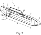
- FIG. 2 shows a sectional view of another embodiment of the multi-function pod 1.
- the pod 1 has a first tank area 3 in the front region of the pod 1, a so-called fore tank.
- the pod 1 has yet another tank area 5 in the rear area of the pod 1, a so-called aft tank.
- the first tank area 3 is connected to an additional tank area 3 ', on the side of the central area 4 of the pod 1 facing the aircraft.
- the further tank area 5 is connected to an additional tank area 5 ', on the side of the middle area 4 of the pod 1 facing the aircraft.
- the receiving device 41 for receiving holding devices or discharge devices 46 is arranged on the side of the central area 4 of the pod 1 facing the aircraft.
- the loading opening 11 of the loading area 4 can be closed with a closure device 11.
- the closure device 11 consists of a closure mechanism 112 and a closure flap 111.
- the closure flap 111 can be opened and the further load 42 (not shown) can be fastened to the holding device or ejection device 46.
- FIGS FIGS. 4 to 7 Various exemplary configurations of loading of the loading area 4 are shown in FIGS FIGS. 4 to 7 shown.
- FIG. 3 shows various embodiments of the positioning of ejectors 46.
- This shows the FIG. 3a a first configuration of the arrangement of a discharge device 46 in the receiving device 41 of the pod 1.
- the receiving device 41 has three slots in the illustrated embodiment of the pod 1, in which discharge devices 46 or holding devices (not shown) can be attached. By forming a slot or guide or rail, along the extension direction of the pod 1, can be arranged drop-off devices 46 and holding devices variable.
- another load not shown
- FIG. 3b illustrated positioning of the discharge devices 46 for example, two other loads (not shown) next to each other on the discharge devices 46 are releasably secured.
- FIG. 3a illustrated embodiment of advantage.
- FIG. 3b illustrated embodiment of advantage.
- 2 smaller loads can be attached next to each other.
- positions of the discharge devices 46 can be combined with each other.
- a centrally disposed discharge device 46 and two discharge devices 46 arranged next to one another can be arranged one behind the other in the receiving device 41.
- the possibility of Combinations here depends only on the number of slots and the width of the pod 1, as well as the length of the loading area 4 of the pod. 1
- FIG. 4 shows various views of an embodiment of the multi-function pod 1 with a rocket 44. This shows FIG. 4a a side view of the multi-function pod 1 in section. In FIG. 4b is a sectional view of the multifunction pod 1 off FIG. 4a shown transversely to the longitudinal axis of the pod 1.
- the multi-function pod 1 has as an additional load 42 in the further area 4 of the pod 1 a discharge device 46 with a rocket 44.
- the rocket 44 is releasably attached to a discharge device 46 in the illustrated embodiment.
- the discharge device 46 is attached to the receiving device 41 of the pod 1.
- the receiving device 41 is covered by the tank area 3 '.
- signals can be transmitted from the aircraft to the launching device 46 or to the missile 44 itself, or in the reverse direction from the launching device 46 or the rocket 44 to the aircraft.
- FIG. 5 shows various views of an embodiment of the multi-function pod 1 with a plurality of bombs 45.
- This shows FIG. 5a a side view of the multi-function pod 1 in section.
- FIG. 5b is a sectional view of the multifunction pod 1 off FIG. 5a shown transversely to the longitudinal axis of the pod 1.
- the multi-function pod 1 has in the illustrated embodiment as another load 42 in the wider area 4 of Pods 1 a dropping device 46 with multiple bombs 45 on.
- the bombs 45 are releasably secured in the illustrated embodiment to a common dropping device 46 for four bombs 45.
- the common discharge device 46 has in the illustrated embodiment, four positions at which bombs 45 can be attached.
- the common discharge device 46 is attached to the receiving device 41 of the pod 1. In the FIG. 5b the receiving device 41 is covered by the tank area 3 'of the pod 1. Via a wireless or wired signal connection (not shown), for example, signals can be transmitted from the aircraft to the discharge device 46 or to the bomb 45 itself or in the reverse direction from the discharge device 46 or the bomb 45 to the aircraft.
- bombs 45 are shown, which are detachably attached to the discharge device, depending on the size of the loading area 4 or depending on the size of the attached bombs and / or missiles, these in different combinations or numbers in the loading area 4 of the pod 1 are housed.
- FIG. 6 shows various views of an embodiment of the multi-function pod with a tank container 43 as another load 42.
- This shows FIG. 6a a side view of the multi-function pod 1 in section.
- FIG. 6b is a sectional view of the multifunction pod 1 off FIG. 6a shown transversely to the longitudinal axis of the pod 1.
- the multi-function pod 1 has a tank container 43 as a further load 42 in the wider area 4 of the pod 1.
- the tank container 43 is attached via a holding device 46 to the receiving device 41 of the pod 1.
- the holding device 46 has an adapter (not shown).
- the adapter includes, for example, a sealed port for the fuel line which can be connected to the fuel tank 43 to provide fuel communication between the fuel tank 43 and the support 46 and further to the aircraft.
- the aircraft may have a corresponding fuel pump.
- the tank container 43 may be provided with a fuel pump which pumps the fuel from the container 43 into the aircraft.
- fuel can be circulated internally and externally between the available tank containers, such as, for example, the tank container 43, the first tank area 3 and the second tank area 5.
- fuel from the aircraft's own or internal tank in the tank area 3, 5 of the pod 1 or in the tank container 43, or vice versa can be pumped for load balancing.
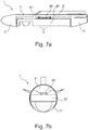
- FIG. 7 shows various views of an embodiment of the multi-function pod 1 with a sensor device 47 as another load.
- This shows Figure 7a a side view of the multi-function pod 1 in section.
- Figure 7b is a sectional view of the multifunction pod 1 off Figure 7a shown transversely to the longitudinal axis of the pod 1.
- the multi-function pod 1 has a sensor device 47 as a further load 42 in the wider area 4 of the pod 1.
- the sensor device 47 consists in the illustrated embodiment of a Container having, for example, a surveillance camera and electronic components for recording and controlling the surveillance camera, as well as for communicating the sensor device 47 with an aircraft or a ground station.
- the sensor device 47 is fastened to the receiving device 41 of the pod 1 via a holding device 46.
- the receiving device 41 is covered by the tank area 3 'of the pod 1.
- the holding device 46 is firmly connected to the sensor device 47, for example.
- the holding device 46 can be latched into the receiving device 41, for example.
- signals can be transmitted from the sensor device 47 to the aircraft or from the aircraft to the sensor device 47.
- the signals can be transmitted for example by cable and / or wireless from the sensor device 47 to the adapter and from the adapter to the aircraft, or from the aircraft to the sensor device 47.
Landscapes
- Engineering & Computer Science (AREA)
- Aviation & Aerospace Engineering (AREA)
- General Engineering & Computer Science (AREA)
- Tires In General (AREA)
- Filling Or Discharging Of Gas Storage Vessels (AREA)
- Details Of Aerials (AREA)
Claims (12)
- Aéronef, comprenant une nacelle multifonction (1) fixée de manière amovible à l'aéronef,
la nacelle (1) comprenant au moins deux zones (3, 4) séparées l'une de l'autre ;
au moins une première zone (3) de la nacelle (1) étant destinée à recevoir du carburant, la première zone (3) de la nacelle (1) destinée à recevoir du carburant étant disposée dans la région avant de la nacelle (1) ;
une deuxième zone (4) de la nacelle (1) comprenant au moins un dispositif de réception (41) servant à fixer de manière amovible au moins une charge supplémentaire (42) ;
la charge supplémentaire (42) pouvant être fixée de manière amovible au dispositif de réception (41) par le biais d'une ouverture de chargement (11) sur le côté de la nacelle (1) opposé à l'aéronef,
une troisième zone (5) de la nacelle (1) étant destinée à recevoir du carburant, la troisième zone (5) de la nacelle (1) étant disposée dans la région arrière de la nacelle (1),
la deuxième zone (4) étant disposée entre la première zone (3) et la troisième zone (5) dans la direction longitudinale de la nacelle (1),
la nacelle multifonction (1) pouvant être détachée de l'aéronef pendant un vol de celui-ci, caractérisé en ce que les zones (3, 5) destinées à recevoir du carburant s'étendent, sur le côté de la nacelle tourné vers l'aéronef, au moins partiellement dans la deuxième zone (4), et le dispositif de réception (41) étant disposé entre les zones (3, 5) s'étendant au moins partiellement dans la deuxième zone (4) et destinées à recevoir du carburant. - Aéronef selon la revendication 1,
dans lequel, par le biais du dispositif de réception (41), différents types de charge (42) peuvent être fixés de manière amovible et de façon variable dans la deuxième zone (4). - Aéronef selon l'une quelconque des revendications précédentes,
dans lequel la charge supplémentaire (42) est au moins un contenant (43) destiné à recevoir du carburant. - Aéronef selon la revendication 3,
dans lequel le dispositif de réception (41) comprend au moins un adaptateur servant à prélever du carburant à partir du contenant (43) vers l'aéronef ou à remplir le contenant (43) de carburant provenant de l'aéronef par le biais d'un dispositif de ravitaillement externe. - Aéronef selon la revendication 1 ou 2,
dans lequel la charge supplémentaire (42) est au moins un missile (44) ou au moins une bombe (45). - Aéronef selon la revendication 5,
dans lequel le dispositif de réception (41) comprend au moins un dispositif de largage (46) pour un ou plusieurs missiles (44). - Aéronef selon la revendication 5,
dans lequel le dispositif de réception (41) comprend au moins un dispositif de largage (46) pour une ou plusieurs bombes (45). - Aéronef selon la revendication 6 ou 7,
dans lequel le dispositif de réception (41) comprend au moins un adaptateur (411) servant à commander le largage des missiles (44) ou des bombes (45) par le biais de l'aéronef. - Aéronef selon l'une quelconque des revendications 6 à 8,
dans lequel plusieurs missiles (44) et/ou bombes (45) peuvent être fixés de manière amovible au dispositif de réception (41) parallèlement et/ou les uns derrière les autres. - Aéronef selon la revendication 1 ou 2,
dans lequel la charge supplémentaire (42) est au moins un dispositif de détection (47). - Aéronef selon la revendication 10,
dans lequel le dispositif de réception (41) comprend au moins un adaptateur servant à la communication de l'aéronef avec le dispositif de détection (47). - Aéronef selon l'une quelconque des revendications précédentes,
dans lequel l'ouverture de chargement (11) peut être fermée à l'aide d'au moins un dispositif de fermeture (12).
Applications Claiming Priority (1)
| Application Number | Priority Date | Filing Date | Title |
|---|---|---|---|
| DE102015004111.8A DE102015004111A1 (de) | 2015-03-31 | 2015-03-31 | Multifunktions-Pod für ein Flugzeug |
Publications (2)
| Publication Number | Publication Date |
|---|---|
| EP3075657A1 EP3075657A1 (fr) | 2016-10-05 |
| EP3075657B1 true EP3075657B1 (fr) | 2019-01-30 |
Family
ID=55640581
Family Applications (1)
| Application Number | Title | Priority Date | Filing Date |
|---|---|---|---|
| EP16162160.2A Active EP3075657B1 (fr) | 2015-03-31 | 2016-03-24 | Nacelle multifonction pour un avion |
Country Status (4)
| Country | Link |
|---|---|
| US (1) | US10086941B2 (fr) |
| EP (1) | EP3075657B1 (fr) |
| DE (1) | DE102015004111A1 (fr) |
| ES (1) | ES2720799T3 (fr) |
Families Citing this family (17)
| Publication number | Priority date | Publication date | Assignee | Title |
|---|---|---|---|---|
| US10259560B2 (en) * | 2016-09-20 | 2019-04-16 | Bell Helicopter Textron Inc. | Modular payload systems for aircraft |
| US10640215B2 (en) * | 2016-09-20 | 2020-05-05 | Textron Innovations Inc. | Modular refueling systems for aircraft |
| WO2018188054A1 (fr) * | 2017-04-14 | 2018-10-18 | 深圳市方鹏科技有限公司 | Système de largage séparé de réservoir de carburant destiné à un véhicule aérien sans pilote |
| US10800526B2 (en) * | 2017-05-10 | 2020-10-13 | Textron Innovations Inc. | Aircraft adapter |
| CN108069038B (zh) * | 2017-12-13 | 2020-12-29 | 中国航空工业集团公司成都飞机设计研究所 | 一种机载三联式混合悬挂系统及使用方法 |
| EP3540362B1 (fr) * | 2018-03-12 | 2021-06-30 | Textron Systems Corporation | Adaptateur de munitions 1-à-n pour une plateforme aéroportée |
| CN108482679B (zh) * | 2018-03-19 | 2023-09-29 | 成都飞机工业(集团)有限责任公司 | 一种同时吊装两架无人机的吊舱系统 |
| US10946963B2 (en) * | 2018-08-21 | 2021-03-16 | Wing Aviation Llc | External containment apparatus for unmanned aerial vehicle |
| US11753164B2 (en) * | 2020-05-04 | 2023-09-12 | Anduril Industries, Inc. | Rotating release launching system |
| US11214370B2 (en) * | 2020-05-04 | 2022-01-04 | Area-I Inc. | Rotating release launching system |
| US12351310B2 (en) * | 2020-05-04 | 2025-07-08 | Anduril Industries, Inc. | Rotating release launching system |
| US11753137B2 (en) * | 2021-08-31 | 2023-09-12 | Textron Systems Corporation | Utilizing a customizable fuselage assembly for an unmanned aerial vehicle |
| DE102022000496A1 (de) | 2022-02-09 | 2023-08-10 | Diehl Defence Gmbh & Co. Kg | Trägerplattform zum Abschießen oder Abwerfen eines unbemannten Flugkörpers auf ein Ziel und Verfahren zum Betrieb einer solchen Trägerplattform |
| DE102022120468A1 (de) | 2022-08-12 | 2022-09-29 | Daimler Truck AG | Elektrischer Energiespeicher für ein zumindest teilweise elektrisch betriebenes Kraftfahrzeug sowie Verfahren |
| US12196528B2 (en) * | 2023-03-01 | 2025-01-14 | The Boeing Company | Interchangeable systems and methods for launching stores from aircraft |
| US20250256868A1 (en) * | 2024-02-13 | 2025-08-14 | Tesseract Ventures, Llc | Modular system for drones |
| DE102024118744A1 (de) * | 2024-07-02 | 2026-01-08 | Airbus Defence and Space GmbH | Waffenbehälter für ein schwer ortbares luftfahrzeug und selbiges |
Family Cites Families (10)
| Publication number | Priority date | Publication date | Assignee | Title |
|---|---|---|---|---|
| US2731885A (en) * | 1956-01-24 | nolan | ||
| GB754429A (en) * | 1952-05-12 | 1956-08-08 | Fairey Aviat Co Ltd | Improvements relating to containers for attachment to aircraft |
| US2816483A (en) * | 1952-10-06 | 1957-12-17 | Northrop Aircraft Inc | Exhaust actuated missile exit door |
| GB780722A (en) * | 1955-06-13 | 1957-08-07 | Northrop Aircraft Inc | Improvements in or relating to rocket and fuel pod |
| GB777919A (en) * | 1955-11-08 | 1957-06-26 | Northrop Aircraft Inc | Improvements in or relating to rocket-launchers for aircraft |
| US3009730A (en) * | 1958-08-13 | 1961-11-21 | Gen Dynamics Corp | Ejector for external carried stores |
| CH431287A (de) * | 1965-01-21 | 1967-02-28 | Oerlikon Buehrle Holding Ag | Behälter an einem Flugzeug für Raketen und Brennstoff |
| AU2002353467A1 (en) * | 2002-05-21 | 2003-12-02 | Nir Padan | System and method for enhancing the payload capacity, carriage efficiency, and adaptive flexibility of external stores mounted on an aerial vehicle |
| US8205536B2 (en) * | 2007-06-13 | 2012-06-26 | Efw Inc. | Integrated weapons pod |
| FR2987032B1 (fr) * | 2012-02-17 | 2014-11-07 | Gaillard Patrick Didier | Systeme d'emport de munitions de precision de petite taille sur aeronef |
-
2015
- 2015-03-31 DE DE102015004111.8A patent/DE102015004111A1/de not_active Ceased
-
2016
- 2016-03-24 EP EP16162160.2A patent/EP3075657B1/fr active Active
- 2016-03-24 ES ES16162160T patent/ES2720799T3/es active Active
- 2016-03-28 US US15/082,219 patent/US10086941B2/en active Active
Non-Patent Citations (1)
| Title |
|---|
| None * |
Also Published As
| Publication number | Publication date |
|---|---|
| ES2720799T3 (es) | 2019-07-24 |
| US10086941B2 (en) | 2018-10-02 |
| EP3075657A1 (fr) | 2016-10-05 |
| DE102015004111A1 (de) | 2016-10-06 |
| US20160288906A1 (en) | 2016-10-06 |
Similar Documents
| Publication | Publication Date | Title |
|---|---|---|
| EP3075657B1 (fr) | Nacelle multifonction pour un avion | |
| EP3548833B1 (fr) | Dispositif de lancement avec missile pour intercepter des drones hostiles | |
| DE102010010508B4 (de) | Unbemanntes Luftfahrzeug mit einem Nutzlastraum | |
| DE10119221B4 (de) | Verborgenes eingekapseltes Luftmunitionsauswurfsystem | |
| DE3132190A1 (de) | Tragvorrichtung fuer eine abwurflast an einem flugzeug | |
| EP1752376A2 (fr) | Aéronef, en particulier aéronef téléguidé, avec au moins une soute d'armes | |
| DE10342565B4 (de) | Vorrichtung und Verfahren für das Absetzen von Marschflugkörpern mittels Airdrop-Launchern aus Transportflugzeugen | |
| DE102014005300B4 (de) | Waffenträger zur Anbringung von zumindest einem unbemannten Flugkörper an einem Trägerluftfahrzeug, Waffensystem und Luftfahrzeug | |
| DE102021000574B4 (de) | Mehrkörperflugsystem | |
| DE102015113092B4 (de) | Verfahren zum Aussetzen unbemannter Flugobjekte von einem Mutterflugzeug | |
| DE102005042484B4 (de) | Unbemannter Gleitflugkörper | |
| DE102012112489B4 (de) | Drehflügler als Plattform für UAV-Missionen | |
| DE10338963A1 (de) | Verfahren und Vorrichtungen für das Absetzen von Marschflugkörpern unter Ausziehplattformen aus Transportflugzeugen mittels Airdrop-Methode | |
| EP4459221A1 (fr) | Munition flottante pour tir par des dispositifs et systèmes existants | |
| DE102008017975A1 (de) | Unbemannter Flugkörper und Verfahren zur Flugführung | |
| DE19518312C1 (de) | Antriebsloser Flugkörper | |
| DE10313279A1 (de) | Verfahren und Vorrichtungen für das Absetzen von aerodynamisch instabilen Marschflugkörpern aus Transportflugzeugen | |
| DE10337085B4 (de) | Verfahren und Vorrichtung für die Reichweitenvergrößerung von Marschflugkörpern | |
| EP3267140A1 (fr) | Véhicule militaire | |
| DE102023001795B4 (de) | Wiederverwendbare flugvorrichtung zur abwehr von einzelnen oder von mehreren flugobjekten in einem örtlich und/oder zeitlich koordinierten verbund | |
| DE102015014502A1 (de) | Hilfstragflügeleinrichtung | |
| DE102007056661A1 (de) | Unbemannter Flugkörper | |
| DE102015105976A1 (de) | Kleinfluggerät | |
| DE102024110250A1 (de) | Aufnahmevorrichtung für lenkflugkörper zur luftabsetzung aus luftfahrzeugen und absetzvorrichtung mit selbiger | |
| DE102024110249A1 (de) | Verfahren zum steuern von lenkflugkörpern sowie lenkflugkörper und luftfahrzeug |
Legal Events
| Date | Code | Title | Description |
|---|---|---|---|
| PUAI | Public reference made under article 153(3) epc to a published international application that has entered the european phase |
Free format text: ORIGINAL CODE: 0009012 |
|
| AK | Designated contracting states |
Kind code of ref document: A1 Designated state(s): AL AT BE BG CH CY CZ DE DK EE ES FI FR GB GR HR HU IE IS IT LI LT LU LV MC MK MT NL NO PL PT RO RS SE SI SK SM TR |
|
| AX | Request for extension of the european patent |
Extension state: BA ME |
|
| STAA | Information on the status of an ep patent application or granted ep patent |
Free format text: STATUS: REQUEST FOR EXAMINATION WAS MADE |
|
| 17P | Request for examination filed |
Effective date: 20170404 |
|
| RBV | Designated contracting states (corrected) |
Designated state(s): AL AT BE BG CH CY CZ DE DK EE ES FI FR GB GR HR HU IE IS IT LI LT LU LV MC MK MT NL NO PL PT RO RS SE SI SK SM TR |
|
| STAA | Information on the status of an ep patent application or granted ep patent |
Free format text: STATUS: EXAMINATION IS IN PROGRESS |
|
| RIC1 | Information provided on ipc code assigned before grant |
Ipc: F41F 5/00 20060101ALI20180212BHEP Ipc: F41F 3/06 20060101ALI20180212BHEP Ipc: F41F 3/065 20060101ALI20180212BHEP Ipc: B64D 1/08 20060101ALI20180212BHEP Ipc: B64D 37/12 20060101ALI20180212BHEP Ipc: B64D 1/04 20060101AFI20180212BHEP Ipc: B64D 7/00 20060101ALI20180212BHEP Ipc: F41F 7/00 20060101ALI20180212BHEP Ipc: F41F 3/052 20060101ALI20180212BHEP |
|
| 17Q | First examination report despatched |
Effective date: 20180302 |
|
| GRAP | Despatch of communication of intention to grant a patent |
Free format text: ORIGINAL CODE: EPIDOSNIGR1 |
|
| STAA | Information on the status of an ep patent application or granted ep patent |
Free format text: STATUS: GRANT OF PATENT IS INTENDED |
|
| INTG | Intention to grant announced |
Effective date: 20180820 |
|
| GRAS | Grant fee paid |
Free format text: ORIGINAL CODE: EPIDOSNIGR3 |
|
| GRAA | (expected) grant |
Free format text: ORIGINAL CODE: 0009210 |
|
| STAA | Information on the status of an ep patent application or granted ep patent |
Free format text: STATUS: THE PATENT HAS BEEN GRANTED |
|
| AK | Designated contracting states |
Kind code of ref document: B1 Designated state(s): AL AT BE BG CH CY CZ DE DK EE ES FI FR GB GR HR HU IE IS IT LI LT LU LV MC MK MT NL NO PL PT RO RS SE SI SK SM TR |
|
| REG | Reference to a national code |
Ref country code: GB Ref legal event code: FG4D Free format text: NOT ENGLISH |
|
| REG | Reference to a national code |
Ref country code: CH Ref legal event code: EP |
|
| REG | Reference to a national code |
Ref country code: AT Ref legal event code: REF Ref document number: 1093043 Country of ref document: AT Kind code of ref document: T Effective date: 20190215 |
|
| REG | Reference to a national code |
Ref country code: IE Ref legal event code: FG4D Free format text: LANGUAGE OF EP DOCUMENT: GERMAN |
|
| REG | Reference to a national code |
Ref country code: DE Ref legal event code: R096 Ref document number: 502016003254 Country of ref document: DE |
|
| REG | Reference to a national code |
Ref country code: LT Ref legal event code: MG4D |
|
| REG | Reference to a national code |
Ref country code: NL Ref legal event code: MP Effective date: 20190130 |
|
| REG | Reference to a national code |
Ref country code: ES Ref legal event code: FG2A Ref document number: 2720799 Country of ref document: ES Kind code of ref document: T3 Effective date: 20190724 |
|
| PG25 | Lapsed in a contracting state [announced via postgrant information from national office to epo] |
Ref country code: PL Free format text: LAPSE BECAUSE OF FAILURE TO SUBMIT A TRANSLATION OF THE DESCRIPTION OR TO PAY THE FEE WITHIN THE PRESCRIBED TIME-LIMIT Effective date: 20190130 Ref country code: LT Free format text: LAPSE BECAUSE OF FAILURE TO SUBMIT A TRANSLATION OF THE DESCRIPTION OR TO PAY THE FEE WITHIN THE PRESCRIBED TIME-LIMIT Effective date: 20190130 Ref country code: FI Free format text: LAPSE BECAUSE OF FAILURE TO SUBMIT A TRANSLATION OF THE DESCRIPTION OR TO PAY THE FEE WITHIN THE PRESCRIBED TIME-LIMIT Effective date: 20190130 Ref country code: SE Free format text: LAPSE BECAUSE OF FAILURE TO SUBMIT A TRANSLATION OF THE DESCRIPTION OR TO PAY THE FEE WITHIN THE PRESCRIBED TIME-LIMIT Effective date: 20190130 Ref country code: PT Free format text: LAPSE BECAUSE OF FAILURE TO SUBMIT A TRANSLATION OF THE DESCRIPTION OR TO PAY THE FEE WITHIN THE PRESCRIBED TIME-LIMIT Effective date: 20190530 Ref country code: NO Free format text: LAPSE BECAUSE OF FAILURE TO SUBMIT A TRANSLATION OF THE DESCRIPTION OR TO PAY THE FEE WITHIN THE PRESCRIBED TIME-LIMIT Effective date: 20190430 Ref country code: NL Free format text: LAPSE BECAUSE OF FAILURE TO SUBMIT A TRANSLATION OF THE DESCRIPTION OR TO PAY THE FEE WITHIN THE PRESCRIBED TIME-LIMIT Effective date: 20190130 |
|
| PG25 | Lapsed in a contracting state [announced via postgrant information from national office to epo] |
Ref country code: GR Free format text: LAPSE BECAUSE OF FAILURE TO SUBMIT A TRANSLATION OF THE DESCRIPTION OR TO PAY THE FEE WITHIN THE PRESCRIBED TIME-LIMIT Effective date: 20190501 Ref country code: HR Free format text: LAPSE BECAUSE OF FAILURE TO SUBMIT A TRANSLATION OF THE DESCRIPTION OR TO PAY THE FEE WITHIN THE PRESCRIBED TIME-LIMIT Effective date: 20190130 Ref country code: RS Free format text: LAPSE BECAUSE OF FAILURE TO SUBMIT A TRANSLATION OF THE DESCRIPTION OR TO PAY THE FEE WITHIN THE PRESCRIBED TIME-LIMIT Effective date: 20190130 Ref country code: BG Free format text: LAPSE BECAUSE OF FAILURE TO SUBMIT A TRANSLATION OF THE DESCRIPTION OR TO PAY THE FEE WITHIN THE PRESCRIBED TIME-LIMIT Effective date: 20190430 Ref country code: LV Free format text: LAPSE BECAUSE OF FAILURE TO SUBMIT A TRANSLATION OF THE DESCRIPTION OR TO PAY THE FEE WITHIN THE PRESCRIBED TIME-LIMIT Effective date: 20190130 Ref country code: IS Free format text: LAPSE BECAUSE OF FAILURE TO SUBMIT A TRANSLATION OF THE DESCRIPTION OR TO PAY THE FEE WITHIN THE PRESCRIBED TIME-LIMIT Effective date: 20190530 |
|
| PG25 | Lapsed in a contracting state [announced via postgrant information from national office to epo] |
Ref country code: MC Free format text: LAPSE BECAUSE OF FAILURE TO SUBMIT A TRANSLATION OF THE DESCRIPTION OR TO PAY THE FEE WITHIN THE PRESCRIBED TIME-LIMIT Effective date: 20190130 Ref country code: AL Free format text: LAPSE BECAUSE OF FAILURE TO SUBMIT A TRANSLATION OF THE DESCRIPTION OR TO PAY THE FEE WITHIN THE PRESCRIBED TIME-LIMIT Effective date: 20190130 Ref country code: DK Free format text: LAPSE BECAUSE OF FAILURE TO SUBMIT A TRANSLATION OF THE DESCRIPTION OR TO PAY THE FEE WITHIN THE PRESCRIBED TIME-LIMIT Effective date: 20190130 Ref country code: EE Free format text: LAPSE BECAUSE OF FAILURE TO SUBMIT A TRANSLATION OF THE DESCRIPTION OR TO PAY THE FEE WITHIN THE PRESCRIBED TIME-LIMIT Effective date: 20190130 Ref country code: RO Free format text: LAPSE BECAUSE OF FAILURE TO SUBMIT A TRANSLATION OF THE DESCRIPTION OR TO PAY THE FEE WITHIN THE PRESCRIBED TIME-LIMIT Effective date: 20190130 Ref country code: SK Free format text: LAPSE BECAUSE OF FAILURE TO SUBMIT A TRANSLATION OF THE DESCRIPTION OR TO PAY THE FEE WITHIN THE PRESCRIBED TIME-LIMIT Effective date: 20190130 Ref country code: CZ Free format text: LAPSE BECAUSE OF FAILURE TO SUBMIT A TRANSLATION OF THE DESCRIPTION OR TO PAY THE FEE WITHIN THE PRESCRIBED TIME-LIMIT Effective date: 20190130 |
|
| REG | Reference to a national code |
Ref country code: CH Ref legal event code: PL Ref country code: DE Ref legal event code: R097 Ref document number: 502016003254 Country of ref document: DE |
|
| PG25 | Lapsed in a contracting state [announced via postgrant information from national office to epo] |
Ref country code: SM Free format text: LAPSE BECAUSE OF FAILURE TO SUBMIT A TRANSLATION OF THE DESCRIPTION OR TO PAY THE FEE WITHIN THE PRESCRIBED TIME-LIMIT Effective date: 20190130 Ref country code: LU Free format text: LAPSE BECAUSE OF NON-PAYMENT OF DUE FEES Effective date: 20190324 |
|
| PLBE | No opposition filed within time limit |
Free format text: ORIGINAL CODE: 0009261 |
|
| STAA | Information on the status of an ep patent application or granted ep patent |
Free format text: STATUS: NO OPPOSITION FILED WITHIN TIME LIMIT |
|
| REG | Reference to a national code |
Ref country code: BE Ref legal event code: MM Effective date: 20190331 |
|
| 26N | No opposition filed |
Effective date: 20191031 |
|
| PG25 | Lapsed in a contracting state [announced via postgrant information from national office to epo] |
Ref country code: IE Free format text: LAPSE BECAUSE OF NON-PAYMENT OF DUE FEES Effective date: 20190324 Ref country code: CH Free format text: LAPSE BECAUSE OF NON-PAYMENT OF DUE FEES Effective date: 20190331 Ref country code: LI Free format text: LAPSE BECAUSE OF NON-PAYMENT OF DUE FEES Effective date: 20190331 |
|
| PG25 | Lapsed in a contracting state [announced via postgrant information from national office to epo] |
Ref country code: BE Free format text: LAPSE BECAUSE OF NON-PAYMENT OF DUE FEES Effective date: 20190331 Ref country code: SI Free format text: LAPSE BECAUSE OF FAILURE TO SUBMIT A TRANSLATION OF THE DESCRIPTION OR TO PAY THE FEE WITHIN THE PRESCRIBED TIME-LIMIT Effective date: 20190130 |
|
| PG25 | Lapsed in a contracting state [announced via postgrant information from national office to epo] |
Ref country code: TR Free format text: LAPSE BECAUSE OF FAILURE TO SUBMIT A TRANSLATION OF THE DESCRIPTION OR TO PAY THE FEE WITHIN THE PRESCRIBED TIME-LIMIT Effective date: 20190130 |
|
| PG25 | Lapsed in a contracting state [announced via postgrant information from national office to epo] |
Ref country code: MT Free format text: LAPSE BECAUSE OF FAILURE TO SUBMIT A TRANSLATION OF THE DESCRIPTION OR TO PAY THE FEE WITHIN THE PRESCRIBED TIME-LIMIT Effective date: 20190130 |
|
| PG25 | Lapsed in a contracting state [announced via postgrant information from national office to epo] |
Ref country code: CY Free format text: LAPSE BECAUSE OF FAILURE TO SUBMIT A TRANSLATION OF THE DESCRIPTION OR TO PAY THE FEE WITHIN THE PRESCRIBED TIME-LIMIT Effective date: 20190130 |
|
| PG25 | Lapsed in a contracting state [announced via postgrant information from national office to epo] |
Ref country code: HU Free format text: LAPSE BECAUSE OF FAILURE TO SUBMIT A TRANSLATION OF THE DESCRIPTION OR TO PAY THE FEE WITHIN THE PRESCRIBED TIME-LIMIT; INVALID AB INITIO Effective date: 20160324 |
|
| REG | Reference to a national code |
Ref country code: AT Ref legal event code: MM01 Ref document number: 1093043 Country of ref document: AT Kind code of ref document: T Effective date: 20210324 |
|
| PG25 | Lapsed in a contracting state [announced via postgrant information from national office to epo] |
Ref country code: MK Free format text: LAPSE BECAUSE OF FAILURE TO SUBMIT A TRANSLATION OF THE DESCRIPTION OR TO PAY THE FEE WITHIN THE PRESCRIBED TIME-LIMIT Effective date: 20190130 |
|
| PG25 | Lapsed in a contracting state [announced via postgrant information from national office to epo] |
Ref country code: AT Free format text: LAPSE BECAUSE OF NON-PAYMENT OF DUE FEES Effective date: 20210324 |
|
| PGFP | Annual fee paid to national office [announced via postgrant information from national office to epo] |
Ref country code: ES Payment date: 20250429 Year of fee payment: 10 |
|
| PGFP | Annual fee paid to national office [announced via postgrant information from national office to epo] |
Ref country code: GB Payment date: 20260324 Year of fee payment: 11 |
|
| PGFP | Annual fee paid to national office [announced via postgrant information from national office to epo] |
Ref country code: DE Payment date: 20260319 Year of fee payment: 11 |
|
| PGFP | Annual fee paid to national office [announced via postgrant information from national office to epo] |
Ref country code: IT Payment date: 20260324 Year of fee payment: 11 |
|
| PGFP | Annual fee paid to national office [announced via postgrant information from national office to epo] |
Ref country code: FR Payment date: 20260320 Year of fee payment: 11 |