EP3075690A1 - Procede et dispositif de surveillance de la production d'une machine a tricoter et machine a tricoter - Google Patents
Procede et dispositif de surveillance de la production d'une machine a tricoter et machine a tricoter Download PDFInfo
- Publication number
- EP3075690A1 EP3075690A1 EP16159895.8A EP16159895A EP3075690A1 EP 3075690 A1 EP3075690 A1 EP 3075690A1 EP 16159895 A EP16159895 A EP 16159895A EP 3075690 A1 EP3075690 A1 EP 3075690A1
- Authority
- EP
- European Patent Office
- Prior art keywords
- yarn
- test
- sensor
- yarn feeding
- feeding devices
- Prior art date
- Legal status (The legal status is an assumption and is not a legal conclusion. Google has not performed a legal analysis and makes no representation as to the accuracy of the status listed.)
- Granted
Links
Images





Classifications
-
- D—TEXTILES; PAPER
- D04—BRAIDING; LACE-MAKING; KNITTING; TRIMMINGS; NON-WOVEN FABRICS
- D04B—KNITTING
- D04B15/00—Details of, or auxiliary devices incorporated in, weft knitting machines, restricted to machines of this kind
- D04B15/38—Devices for supplying, feeding, or guiding threads to needles
- D04B15/48—Thread-feeding devices
-
- D—TEXTILES; PAPER
- D04—BRAIDING; LACE-MAKING; KNITTING; TRIMMINGS; NON-WOVEN FABRICS
- D04B—KNITTING
- D04B15/00—Details of, or auxiliary devices incorporated in, weft knitting machines, restricted to machines of this kind
- D04B15/38—Devices for supplying, feeding, or guiding threads to needles
-
- D—TEXTILES; PAPER
- D04—BRAIDING; LACE-MAKING; KNITTING; TRIMMINGS; NON-WOVEN FABRICS
- D04B—KNITTING
- D04B35/00—Details of, or auxiliary devices incorporated in, knitting machines, not otherwise provided for
- D04B35/10—Indicating, warning, or safety devices, e.g. stop motions
-
- D—TEXTILES; PAPER
- D04—BRAIDING; LACE-MAKING; KNITTING; TRIMMINGS; NON-WOVEN FABRICS
- D04B—KNITTING
- D04B35/00—Details of, or auxiliary devices incorporated in, knitting machines, not otherwise provided for
- D04B35/10—Indicating, warning, or safety devices, e.g. stop motions
- D04B35/12—Indicating, warning, or safety devices, e.g. stop motions responsive to thread consumption
-
- D—TEXTILES; PAPER
- D04—BRAIDING; LACE-MAKING; KNITTING; TRIMMINGS; NON-WOVEN FABRICS
- D04B—KNITTING
- D04B35/00—Details of, or auxiliary devices incorporated in, knitting machines, not otherwise provided for
- D04B35/10—Indicating, warning, or safety devices, e.g. stop motions
- D04B35/14—Indicating, warning, or safety devices, e.g. stop motions responsive to thread breakage
- D04B35/16—Indicating, warning, or safety devices, e.g. stop motions responsive to thread breakage with detectors associated with a series of threads
Definitions
- the invention relates to a method and a device for monitoring the production of a knitting machine according to the preambles of the independent claims and to a corresponding knitting machine.
- the control unit polls the sensor devices individually based on a periodic reference signal that is a function of the operating position of the textile machine, according to the data regarding the state of supply of the threads.
- the control unit controls the operation of the textile machine with the data from the sensor devices. It interrupts the operation of the textile machine when a difference occurs between the data obtained from at least one sensor device and the corresponding stored data.
- a production monitoring / adjustment device and a corresponding method for a knitting machine, in particular a circular knitting machine are in the EP 1 370 720 B1 described.
- the apparatus comprises a plurality of knitting systems, a plurality of delivery devices and a computerized unit, the delivery devices being connected to the computerized unit.
- the production monitor / adjuster receives trig signals.
- yarn is delivered to the active knitting systems of a plurality of non-positive delivering delivery devices according to at least two distinct yarn delivery principles.
- the individual yarn quantities are continuously measured by means of sampled actual rotation signals at the delivery devices.
- the individual yarn quantities are compared in the computerized unit with nominal yarn quantities of about a masterpiece and information and / or adjustment measures derived from the comparisons. Tolerances are defined for the comparisons, which are matched in their width to yarn quality and / or yarn path parameters. Exceeding the different tolerance ranges is used to trigger different measures, such as alarm signals, Setting measures or switching off the knitting machine, used.
- the individual amounts of yarn are also used to determine a total amount of yarn and / or a weight of yarn, being converted or converted into equal quantity or weight units.
- the knitting machine with its machine control, the production monitoring / adjustment device and the delivery devices are connected via a bus system, e.g. a CAN bus system or a daisy chain linked.
- a bus system e.g. a CAN bus system or a daisy chain linked.
- yarn quantities of a certain size are compared with their target yarn quantities.
- the individual yarn quantities are determined, for example, for knitting paths which correspond to one or more revolutions of the knitting cylinder of the circular knitting machine.
- the EP 2 270 269 B1 describes a method for detecting the stopping of yarn unwinding from a yarn feeder to a downstream machine.
- the yarn feeder has a stationary drum and a sensor, through whose sensor signal one pulse is generated per loop unwound from the drum.
- the machine is stopped when a measured time since the last pulse exceeds a setpoint for the time between two pulses.
- the setpoint is updated in real time depending on the yarn unwinding speed.
- the object of the invention is to improve a method and a device for monitoring the production of a knitting machine.
- it is the object of the invention to allow a quick stopping of the knitting machine in case of thread standstill or yarn breakage with little effort.
- An inventive method relates to monitoring the production of a knitting machine.
- a knitting machine is designed, for example, as a circular knitting machine or a flat knitting machine.
- a circular knitting machine has several or a plurality of identical or different yarn feeding devices.
- Yarn feeding devices are, for example, positive yarn feeding devices, thread tension controlled yarn feeding devices or storage yarn feeding devices. These yarn feeding devices are used, for example, when making knitwear with patterns.
- the thread delivery takes place at storage yarn feeding devices, in which the thread is withdrawn from a winding body.
- the yarn delivery takes place, in which the yarn is delivered via a driven winding body.
- the thread tension is measured and controlled by changing the rotational speed of the bobbin.
- the yarn delivery of the Postiv yarn feeding devices is a feeding of the thread synchronously to the speed of the knitting machine.
- bobbins of the positive yarn feeding devices e.g. via a gear and toothed belt, driven by the drive of the knitting machine.
- a knitting point is assigned a yarn feeding device.
- a knitting station is associated with two or more yarn feeding devices which alternately or at the same time different, e.g. deliver differently dyed, threads to the knitting point.
- the yarn feeding devices associated with a knitting station are referred to as a group of yarn feeding devices.
- the invention relates to a method for monitoring the yarn delivery of at least two yarn feeding devices or at least two groups of at least two yarn feeding devices, ie the yarn delivery for at least two knitting points.
- a sensor signal having a measuring pulse per unit length of a yarn feeding path is generated by a sensor device which is arranged in the yarn feeding path of the yarn feeding device.
- the generated sensor signals are checked by a control device. Possibly. a stop signal for the knitting machine is generated by the control device.
- the control device For checking the sensor signals of the yarn feeding devices or the groups, the control device is provided with test events by a clock unit.
- the test event is an event after which the verification of the sensor signals by the control device is started.
- control device checks whether at least one measuring pulse has been generated by the sensor devices of the sensor devices of each of the yarn feeding devices or of each of the groups.
- a test event is determined by the clock unit from the sensor signals of at least two yarn feeding devices or from the sensor signals of at least two groups of yarn feeding devices.
- the yarn feeding devices whose sensor signals are used by the clock unit to determine the test events are called monitor thread feeders. Accordingly, the groups used to determine the test events are called monitor groups.
- the number of measuring pulses is determined during each determination of a test event for each yarn feeding device or for each group.
- the numbers of the measuring pulses are set to zero after a check.
- the verification of the sensor signals is triggered by a test event that has been determined by the clock unit from the sensor signals themselves, namely from sensor signals of at least two monitor thread supply devices or at least two monitor groups. This makes it possible with little effort, namely with the aid of sensor signals to be checked, a rapid stopping of the knitting machine in case of thread standstill or yarn breakage.
- Sensor signals from several, ie from at least two monitor thread suppliers or monitor groups are used to determine a test result, so that different ways of working knitting such as knitting or floatation can be considered
- monitor thread suppliers or monitor groups are used. This allows a safe determination of the test results in different ways of working the knitting or failure of a monitor thread feeding device or a monitor group.
- all yarn feeding devices or all groups are used as monitor thread feeding devices or monitor groups. This is the case, for example, when only a few, for example up to 16, yarn feeding devices or groups are monitored.
- a test event is determined by the clock unit if the clock unit has been supplied with at least M measurement pulses by the sensor signals of N of the monitor thread suppliers or of N monitor groups.
- the number M of measurement pulses to be supplied by a sensor signal of a monitor thread supply device or by a monitor group is at least 2.
- the number M of measurement pulses is 2 to 5.
- the number N of monitor thread suppliers or monitor groups, of which M measurement pulses are to be supplied is at least 1. Preferably, the number N is 1 to 10.
- the monitoring device comprises two yarn feeding devices, both are also monitor thread feeding devices, i.
- the sensor signals of both yarn feeding devices are provided to the clock unit.
- a test pulse is e.g. generated when one of the sensor signals S has sent two measuring pulses to the clock unit, wherein the number N of the sensor signals to 1 and the number M of the measuring pulses is set to 2. The same applies to an embodiment of the monitoring device with two groups of yarn feeding devices.
- the control device is provided by the clock unit with the test events as test commands.
- a test command z. B. denotes a program command, by which a check of the sensor signals performing program of the control device is started.
- a test command is generated by the clock unit if a test event has been determined by it.
- control device is provided by the clock unit, the test events as test pulses of a test signal available.
- the clock unit By the clock unit, a test pulse of the test signal is generated whenever a test event was determined by them.
- the sensor signals are checked in separate control units of the control device.
- Each of the separate control units is associated with a yarn feeding device, wherein it is fed to the sensor signal of the yarn feeding device.
- the control units are integrated, for example, in the yarn feeding devices.
- To check all separate control units z. B. provided a test signal with test pulses.
- the separate control units check with each test pulse whether at least one measuring pulse has been generated at its own sensor signal. If necessary, namely e.g. if this is not the case, the respective separate control unit generates a stop signal for the knitting machine.
- the sensor signals are checked in a central control unit of the control device.
- the sensor signals are fed to the central control unit.
- the central control unit is also provided with the test events determined by the clock unit.
- the central control unit checks with each test event whether at least one measuring pulse has been generated for each sensor signal. Possibly. it generates a stop signal for the knitting machine.
- the test events are provided to the central control unit as test pulses of the test signal.
- the length unit of the yarn delivery path corresponds to a wound from a winding body of the yarn feeding device yarn winding or a part of the unwound Garnwindung.
- the yarn turns are passively unwound in storage yarn feeding devices, namely deducted by the knitting machine. In yarn tension controlled yarn feeding devices and in positive yarn feeding devices, the yarn turns are actively drawn off, namely supplied by driven winding bodies.
- various yarn feeding devices are monitored.
- coordinated measuring pulses of their sensor devices are used.
- the length units unrolled per measurement pulse are the same for the various yarn feeders.
- a device for monitoring the production of a knitting machine, in the following monitoring device, comprises at least two yarn feeding devices, to each of which a sensor device is assigned. Each sensor device is designed to generate a sensor signal with one measurement pulse per unit length of a yarn delivery path.
- the monitoring device comprises a control device, which is designed to check the sensor signals of the sensor devices. If necessary, the control device generates a stop signal for the knitting machine.
- the monitoring device comprises a clock unit, which is designed to provide the control device with a test event.
- the clock unit is designed to determine test events from sensor signals of at least two, designated as monitor thread feeding devices, the yarn feeding devices or, of at least two, designated as monitor groups, the groups.
- the control device is designed to check at each test event whether at least one measuring pulse has been generated in the sensor signals of each yarn feeding device or each group.
- the clock unit is connected to the sensor devices of 4 to 16 monitor thread suppliers or monitor groups.
- the clock unit is configured to determine a test event if it has been supplied with measurement pulses by the sensor signals of N of the monitor thread supply devices or by N of the monitor groups, where N is at least 1 and M is at least 2.
- the clock unit is designed to provide the control unit with the test events as test commands.
- the clock unit is designed to generate a test command each time a test event has been determined.
- the clock unit is designed to make available to the control device the test results as test pulses of a test signal.
- the clock unit is configured to generate a test pulse each time a test event has been determined.
- control device has separate control units, which are each connected to the sensor devices of the yarn feeding devices.
- the separate ones are each connected to the sensor devices of the yarn feeding devices.
- Control units are connected to receive the test signal with the test pulses to the clock unit.
- control device has a central control unit.
- the central control unit is connected to the sensor devices of the yarn feeding devices for receiving the sensor signals of all monitored yarn feeding devices.
- the central control unit is connected to the clock unit for receiving the test events.
- the central control unit is connected to the clock unit for receiving a test signal with test pulses.
- control unit is connected to the clock unit for receiving a test command.
- the central control unit and the clock unit z. B. formed as program units.
- the yarn feeding devices have winding bodies, wherein the length unit of the yarn feeding path corresponds to a yarn winding unwound from the winding body or a part of the yarn winding.
- a knitting machine according to the invention is provided with one of the described monitoring devices according to the invention.
- An apparatus according to the invention is provided for monitoring the production of a circular knitting machine 1.
- FIG. 1 shows a schematic view of the circular knitting machine 1 with elements of inventive devices for monitoring the production of the knitting machine, hereinafter referred to as monitoring devices.
- the circular knitting machine 1 has a plurality of yarn feeding devices, namely as storage yarn feeding devices 2, as voltage-controlled yarn feeding devices 3 and trained as positive yarn feeding devices 4 yarn feeding devices.
- the yarn feeding devices 2, 3, 4 are arranged on a plurality of carrier rings 5 of the circular knitting machines 1. In FIG. 1 only some of the yarn feeding devices are shown, with three storage yarn feeding devices 2 on an upper carrier ring 5, three yarn tension controlled yarn feeding devices 3 on a central carrier ring 5 and three positive yarn feeding devices 4 on a lower carrier ring 5.
- the circular knitting machine 1 has, for example for the production of a patterned knitted fabric, for example a jacquard knit, several knitting points 6 on its knitting device, wherein each knitting point 6 is associated, for example, with a yarn feeding device.
- the knitting device comprises z. B. a knitting cylinder 7, the in FIG. 1 is covered by knitting locks 8 and is displayed as an arrow.
- FIG. 1 also shows that the knitting point 6, a thread 9 is fed by a storage yarn feeding device 2.
- the knitting device is rotatably arranged in a frame 10, which is surrounded by a housing 11 in the region below the knitting device and to which the carrier rings 5 are fastened in the region above the knitting device.
- a machine control 12, u. a. for a non-visible drive of the knitting device is disposed adjacent to the housing 10.
- a monitoring device for a jacquard knitting machine. It comprises at least two storage yarn feeding devices 2 and a control unit 13.
- the control unit 13 is how FIG. 1 shows, at a central part of the frame 11 of the circular knitting machine 1, for example, removably attached.
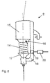
- FIG. 2 shows a storage yarn feeding device 2 with a formed as a storage drum 14 bobbin.
- the stationary storage drum 14 is arranged in front of a housing 15. At the inlet end of the storage drum 14, a take-up element 16 for winding yarn turns on the storage drum 14 is arranged. At the other end, i.e. at the outlet end, the storage drum 14, is e.g. a cone brake 17 is provided. The cone brake 17 is supported by a boom 18 of the housing 15.
- the memory yarn feeding device 2 is associated with a sensor device 19 and a separate control unit 20.
- the sensor device 19 is designed to generate a sensor signal with one measurement pulse I per unit length of a yarn delivery path .DELTA.XF.
- the unit length of the yarn feeding path ⁇ XF corresponds to a yarn winding withdrawn from the storage drum 14.
- the sensor device 19 is e.g. is formed as an optical sensor, which at each withdrawn, i. Passively wound yarn winding generates a measuring pulse I.
- the circumference of the storage drum 14, and thus the length of a yarn turn is 20 cm, i. the unit length of the thread delivery path ⁇ XF is 20 cm.
- the separate control unit 20 has e.g. a microprocessor. It is designed as an electronic module and / or program units.
- the separate control unit 20 is designed to check the sensor signal S of the sensor device 19 and, if necessary, to generate a stop signal ST for the circular knitting machine 1.
- the separate control unit 20 is in the housing 15 and thus in the Storage yarn feeder 2 integrated, but in FIG. 2 shown separately for clarity.
- FIG. 3 shows a block diagram of the circular knitting machine 1 with the monitoring device of the first example.
- Eight of the storage yarn feeding devices 2 and the control unit 13 of the monitoring device can be seen.
- the storage yarn feeding devices 2 are connected to one another and to the control unit 13 via a communication connection 21.
- the communication connection 21 is designed as two lines and guided on the support rings 5 and parts of the frame 11.
- the communication link 21 is in FIG. 1 not shown. Data is exchanged between the connected devices via the communication connection 21.
- the communication connection 21 is designed, for example, as two lines of a CAN-BUS connection, via which a serial data transmission takes place.
- the number J of the storage yarn feeding devices 2 is 2 to 126, or more than 126, of which at least 2, preferably 4 to 16, used as monitor yarn feeding devices.
- the monitoring device 48 comprises storage yarn feeding devices 2 with their sensor devices 19, i. the number J of the storage yarn feeding devices is 48. Of these storage yarn feeding devices 2, 16 are used as monitor thread feeding devices.
- the control unit 13 is connected via a control connection 22 to the circular knitting machine 1, specifically with its machine control 12.
- the control connection 22 is e.g. designed as a control line. Alternatively, it is designed as the communication connection 21 as a CAN-BUS connection.
- FIG. 3 illustrates the path of each thread 9 from a yarn package 23 on the storage yarn feeding device 2 to one of the knitting points 6 on the knitting cylinder 7 of the circular knitting machine first
- FIG. 4 shows a block diagram of this monitoring device, wherein only six of the storage yarn feeding devices 2, their sensor devices 19 and their separate control units 20 can be seen.
- a control device of the monitoring device is formed inter alia by the separate control units 20 of the storage yarn feeding devices 2.
- the control device also includes a control unit K integrated in the control unit 13 for forwarding a stop signal ST to one of the separate control units 20.
- the monitoring device comprises a clock unit T, which is also integrated in the control unit 13.
- the control unit 13 is in FIG. 4 represented by a dashed line around the clock unit T and the control unit K.
- the clock unit T is connected to the sensor devices 19 of the 16 Monitorfadenunter Anlagen. In FIG. 4 It can be seen that the clock unit T is connected to the sensor devices 19 of the three left-hand storage yarn feeding devices 2 used as monitor yarn feeding devices via the control connection 21.
- the clock unit T is designed to determine test results from the sensor signals S of the monitor thread feeders and to provide them as test pulses T3 of a test signal S3. That the clock unit is designed to generate test pulses T3 of a test signal S3. In particular, the clock unit T is designed to generate a test pulse T3 in each case if at least N measurement pulses I have been supplied to the clock unit T of at least N of the sensor signals S of the monitor thread supply devices.
- the separate control units 20 are connected to the clock unit T to receive the test signal S3.
- Each of the separate control units 20 is designed to check at each test pulse T3 of the test signal S3 whether at least one measuring pulse I has been generated in the case of the own sensor signal S. It is designed, if this is not the case, to generate a stop signal ST and send it to the control unit K.
- the control unit K is designed to forward the stop signal ST via the control connection 22 to the machine controller 12 of the circular knitting machine 1.
- the control unit 13 is designed as an electronic device and is used e.g. provided with a microprocessor.
- the clock unit T and the control unit K are designed as electronic units and / or program units of the control unit 13.
- the yarn delivery of all storage yarn feeding devices 2 is monitored to monitor the circular knitting machine 1.
- the respective separate control unit 20 checks the sensor signal S by checking whether at least one measuring pulse I has been generated for each test pulse T3. It generates a stop signal ST for the circular knitting machine 1, if this is not the case.
- test events are determined from the sensor signals S of the monitor thread supply devices and made available as test pulses T3 of a test signal S3. Ie. by the clock unit T test pulses T3 are generated.
- a test pulse T3 is generated when at least N measurement pulses I have been supplied to the clock unit T of at least N of the sensor signals S of the monitor thread supply devices.
- the number N of sensor signals is at least one, preferably 1 to 10.
- the number M of measurement pulses at least two, preferably 2 to 5.
- the number M of measurement pulses is set to 3 and the number N of the sensor signals is set to 2.
- the numbers N and M are variably adjustable depending on the quality of the threads and / or the goods and / or other sizes.
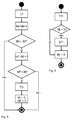
- FIG. 5 shows on the basis of a flowchart the generation of a test pulse T3 by the clock unit T from the sensor signals S of the monitor thread supply devices.
- NF NF + 1. If this is not the case, the procedure is restarted.
- a test pulse T3 of the test signal S3 is generated by the clock unit T.
- FIG. 6 shows by means of a flow chart, the verification of a sensor signal S by the corresponding separate control unit 20th
- the number of measurement pulses Mj of the sensor device S supplied by the sensor device 19 is summed by the corresponding separate control unit 20. This is in FIG. 6 not shown.
- the separate control unit 20 checks whether the number Mj of the measuring pulses is greater than zero.
- a stop signal ST for the circular knitting machine 1 is generated by the control unit 20 and fed to the machine control 12 of the circular knitting machine 1 via the control connection 22.
- the respective number Mj is set to zero by the separate control unit 20.
- the check of the sensor signal S is restarted. It is waiting for a new test pulse T3. Meanwhile, the measurement pulses I of the sensor device 19 are summed up again in the number Mj.
- the verification of the sensor signals S is performed by all separate control units 20 in parallel.
- control unit 13 is integrated in the machine control 12 of the circular knitting machine 1.
- the monitoring device comprises a plurality of yarn tension-controlled yarn feeding devices 3 with driven winding bodies.
- a sensor device for a yarn tension-controlled yarn feeding device 3 is designed, for example, as an encoder, which is arranged on the driven winding body.
- the encoder is designed to generate a sensor signal with measuring pulses for a specific angle of rotation of the winding body and thus for a specific yarn delivery path ⁇ XF.
- the yarn feeding path ⁇ XF of a measuring pulse corresponds to a yarn winding or a part of a yarn winding actively unwound from the winding body, i. delivered, will.
- the monitoring device comprises both storage yarn feeding devices 2 and / or yarn tension-controlled yarn feeding devices 3 and / or positive yarn feeding devices.
- a sensor device for a positive yarn feeding device 4 like that of the yarn tension controlled yarn feeding device, is designed as an encoder on its winding body.
- the measurement pulses for the different yarn feeding devices same Fadenunter admir .DELTA.XF correspond.
- the second example corresponds to that of the first example except for the features shown below.
- FIG. 7 shows a block diagram of the monitoring device of the second example.
- the monitoring device likewise comprises 48 monitored storage yarn feeding devices 2 with their sensor devices 19. Of these, 16 of the storage yarn feeding devices 2 are used as monitor thread feeding devices. In FIG. 7 Six of the storage yarn feeding devices 2 and their sensor devices 19 are shown. Possibly. There are no separate control units for further control functions.
- a monitoring device of the monitoring device comprises a central control unit ZK, which is integrated together with the clock unit T in the control unit 13.
- the central control unit ZK is connected via the communication link 21 for receiving the sensor signals S with all sensor devices 19 and internally, i. within the control unit 13, connected to the clock unit T.
- the central control unit ZK is designed to check at each test pulse T3 of the test signal S3 from the clock unit T whether at least one measuring pulse I has been generated in each sensor signal S of the monitored storage yarn feeding devices 2. It is designed to generate a stop signal ST and to forward it via the control connection 22 to the machine controller 12 of the circular knitting machine 1.
- the number J in this example, as mentioned, is 48.
- a stop signal ST for the circular knitting machine 1 is generated by the central control unit and fed to the machine control 12 of the circular knitting machine 1 via the communication link 22.
- the numbers Mj of the measuring pulses I of the sensor signals are set to zero.
- the verification of the sensor signals S is restarted. That it is waiting for a new test pulse T3. Meanwhile, the measurement pulses Ij of the sensor devices 19 are again summed up in the numbers Mj.
- a monitoring apparatus and a monitoring method of the third example are the same as those of the second example except for the features shown below.
- the central control unit ZK and the clock unit T are integrated in the control unit 13 in common.
- the control unit 13 is connected by its connection to the communication connection 21 with all storage yarn feeding devices 2 for receiving the sensor signals S of all sensor devices 19.
- the clock unit T of the control unit 13 is connected to the sensor devices 19 of the monitor thread supply devices. It is designed to determine test events from the sensor signals S of the 16 monitor thread feeders.
- the central control unit ZK is connected to all sensor devices 19. It is designed to check at each test event made available by the clock unit T whether at least one measuring pulse I has been generated in the sensor signals S of each yarn feeding device 2. It is designed, if this is not the case, to generate a stop signal ST and forward it via the control connection 22 to the machine controller 12 of the circular knitting machine 1.
- the clock unit T and the central control unit ZK are designed, for example, as program units, the test events of the clock unit T being passed to the central control unit ZK as test commands T3 *.
- a test signal with test pulses is not required in this example.
- the yarn delivery of all storage yarn feeding devices 2 is monitored by the monitoring device.
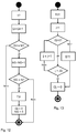
- FIG. 10 shows on the basis of a flowchart the generation of a test event as a test command T3 * by the clock unit T and the by the test command T3 * started checking all sensor signals S by the central control unit ZK.
- test command T3 * is generated by the clock unit T and the central control unit ZK waits for it.
- a stop signal ST for the circular knitting machine 1 is generated by the central control unit ZK and fed to the machine control 12 of the circular knitting machine 1 via the control connection 22.
- the numbers Mi, the numbers Mj and the number NF are set to zero.
- the verification of the sensor signals S is restarted.
- a monitoring apparatus and a monitoring method of the third example are the same as those of the second example except for the features shown below.
- FIG. 11 shows a block diagram of the circular knitting machine 1 with a monitoring device according to the invention of the fourth example, which is provided for a strip knitting machine.
- the yarn delivery of groups G of two storage yarn feeding devices 2 is monitored.
- the two storage yarn feeding devices 2 of a group G supply threads 9, for example of different color.
- the number of storage yarn feeding devices 2 is also 48, and thus the number JG of the groups 24.
- FIG. 11 four of the groups, each with two storage yarn feeding devices 2 and the control unit 13 of the monitoring device can be seen.
- the groups G are each indicated by a dashed line.
- the two storage yarn feeding devices 2 of a group G are each assigned to one of the knitting points 6.
- the circular knitting machine 1 has at each of the knitting points 6 a ringing device 24, which is arranged in the yarn path in front of the knitting point 6.
- the ringing device 24 is designed to select one of the threads 9 of the two storage yarn feeding devices 2 and supply the knitting point 6.
- the central control unit ZK checks the sensor signals S as a function of the test pulses T3 provided by the clock unit T of the control unit 13. It checks whether at least one measuring pulse I has been generated in the sensor signals S of a group. If this is not the case for a group, it generates a stop signal ST for the circular knitting machine 1 and sends it to the machine controller 12.
- FIG. 12 shows on the basis of a flowchart the generation of a test pulse T3 by the clock unit T from the sensor signals S of the monitor groups.
- a test pulse T3 of the test signal S3 is generated by the clock unit T.
- FIG. 13 shows the basis of a flow chart, the verification of the sensor signals S of the groups G by the central control unit ZK.
- the number JG in this example, as mentioned, is 24.
- a stop signal ST for the circular knitting machine 1 is generated by the central control unit ZK and fed to the machine control 12 of the circular knitting machine 1 via the control connection 22.
- the number Gj of the measuring pulses I of the sensor signals S are set to zero.
- the verification of the sensor signals S is restarted. That is, it is waiting for a new test pulse T3. Meanwhile, the measurement pulses Ij of the groups are summed up again in the numbers Gj.
Landscapes
- Engineering & Computer Science (AREA)
- Textile Engineering (AREA)
- Knitting Machines (AREA)
Applications Claiming Priority (1)
| Application Number | Priority Date | Filing Date | Title |
|---|---|---|---|
| DE102015104903.1A DE102015104903B3 (de) | 2015-03-30 | 2015-03-30 | Verfahren und Vorrichtung zur Überwachung der Produktion einer Strickmaschine sowie Strickmaschine |
Publications (2)
| Publication Number | Publication Date |
|---|---|
| EP3075690A1 true EP3075690A1 (fr) | 2016-10-05 |
| EP3075690B1 EP3075690B1 (fr) | 2021-12-22 |
Family
ID=55527415
Family Applications (1)
| Application Number | Title | Priority Date | Filing Date |
|---|---|---|---|
| EP16159895.8A Active EP3075690B1 (fr) | 2015-03-30 | 2016-03-11 | Procede et dispositif de surveillance de la production d'une machine a tricoter et machine a tricoter |
Country Status (4)
| Country | Link |
|---|---|
| EP (1) | EP3075690B1 (fr) |
| CN (1) | CN106012269B (fr) |
| DE (1) | DE102015104903B3 (fr) |
| TW (1) | TWI620845B (fr) |
Cited By (2)
| Publication number | Priority date | Publication date | Assignee | Title |
|---|---|---|---|---|
| EP3699343A1 (fr) * | 2019-02-25 | 2020-08-26 | Memminger-IRO GmbH | Procédé et système de surveillance de la production d'une machine à tricoter pourvue d'une pluralité de dispositifs d'alimentation en fil |
| CN116641182A (zh) * | 2023-03-29 | 2023-08-25 | 福建屹立智能化科技有限公司 | 一种灵活安装的经编机防误触断纱检测自停装置及方法 |
Families Citing this family (1)
| Publication number | Priority date | Publication date | Assignee | Title |
|---|---|---|---|---|
| CN119472567B (zh) * | 2025-01-16 | 2025-04-01 | 浙江联洋先进材料有限公司 | 一种基于物联网的碳纤维经编机运行方法 |
Citations (6)
| Publication number | Priority date | Publication date | Assignee | Title |
|---|---|---|---|---|
| EP0752631B1 (fr) | 1995-07-03 | 2002-04-17 | B.T.S.R. International S.p.A. | Dispositif de surveillance du chargement d'une pluralité de fils pour une machine textile ayant des capteurs encodés et méthode de commande du dispositif |
| EP1370720A1 (fr) | 2001-03-16 | 2003-12-17 | Memminger-IRO GmbH | Procede de reglage/surveillance de production d'un metier a tricoter circulaire et dispositif de reglage/surveillance de production |
| WO2008083691A1 (fr) | 2006-12-22 | 2008-07-17 | Memminger-Iro Gmbh | Dévidoir de fil doté d'un débrayage amélioré |
| EP2270269B1 (fr) | 2009-07-03 | 2011-10-26 | L.G.L. Electronics S.p.A. | Procédé de détection de l'arrêt du déroulement du fil dans un dispositif d'alimentation de fil doté d'un tambour stationnaire |
| DE102012103535B3 (de) * | 2012-04-20 | 2013-10-10 | Memminger-Iro Gmbh | Vorrichtung und Verfahren zur Überwachung der Produktion einer Strickmaschine |
| EP2415916B1 (fr) * | 2010-08-04 | 2015-03-04 | L.G.L. Electronics S.p.A. | Procédé et appareil pour détecter des arrêts accidentels de fil dans une chaîne de fabrication tricotage |
Family Cites Families (6)
| Publication number | Priority date | Publication date | Assignee | Title |
|---|---|---|---|---|
| CN2571800Y (zh) * | 2002-08-15 | 2003-09-10 | 林忠民 | 针织机喂纱器的停车器 |
| ES2289254T3 (es) * | 2003-10-22 | 2008-02-01 | Luigi Omodeo Zorini | Maquina textil y su respectivo procedimiento de control. |
| DE102005050126B3 (de) * | 2005-10-18 | 2007-04-19 | Fraunhofer-Gesellschaft zur Förderung der angewandten Forschung e.V. | Vorrichtung und Verfahren zur überwachten Fadenführung in einer Strickmaschine |
| ITTO20120261A1 (it) * | 2012-03-22 | 2013-09-23 | Lgl Electronics Spa | Metodo di alimentazione/recupero del filato per macchine tessili, ed apparato per l'esecuzione di tale metodo. |
| CN203113045U (zh) * | 2013-03-15 | 2013-08-07 | 中山市斯玛特电子科技有限公司 | 一种电脑横机纱嘴工作检测报警装置 |
| DE102013110988B4 (de) * | 2013-10-02 | 2019-08-29 | Memminger-Iro Gmbh | Verfahren und Vorrichtung zur Überwachung der Produktion einer Strickmaschine sowie Strickmaschine |
-
2015
- 2015-03-30 DE DE102015104903.1A patent/DE102015104903B3/de not_active Expired - Fee Related
-
2016
- 2016-03-11 EP EP16159895.8A patent/EP3075690B1/fr active Active
- 2016-03-28 TW TW105109628A patent/TWI620845B/zh active
- 2016-03-30 CN CN201610189780.8A patent/CN106012269B/zh active Active
Patent Citations (7)
| Publication number | Priority date | Publication date | Assignee | Title |
|---|---|---|---|---|
| EP0752631B1 (fr) | 1995-07-03 | 2002-04-17 | B.T.S.R. International S.p.A. | Dispositif de surveillance du chargement d'une pluralité de fils pour une machine textile ayant des capteurs encodés et méthode de commande du dispositif |
| EP1370720A1 (fr) | 2001-03-16 | 2003-12-17 | Memminger-IRO GmbH | Procede de reglage/surveillance de production d'un metier a tricoter circulaire et dispositif de reglage/surveillance de production |
| EP1370720B1 (fr) | 2001-03-16 | 2006-11-02 | Memminger-IRO GmbH | Procede de reglage/surveillance de production d'un metier a tricoter circulaire et dispositif de reglage/surveillance de production |
| WO2008083691A1 (fr) | 2006-12-22 | 2008-07-17 | Memminger-Iro Gmbh | Dévidoir de fil doté d'un débrayage amélioré |
| EP2270269B1 (fr) | 2009-07-03 | 2011-10-26 | L.G.L. Electronics S.p.A. | Procédé de détection de l'arrêt du déroulement du fil dans un dispositif d'alimentation de fil doté d'un tambour stationnaire |
| EP2415916B1 (fr) * | 2010-08-04 | 2015-03-04 | L.G.L. Electronics S.p.A. | Procédé et appareil pour détecter des arrêts accidentels de fil dans une chaîne de fabrication tricotage |
| DE102012103535B3 (de) * | 2012-04-20 | 2013-10-10 | Memminger-Iro Gmbh | Vorrichtung und Verfahren zur Überwachung der Produktion einer Strickmaschine |
Cited By (2)
| Publication number | Priority date | Publication date | Assignee | Title |
|---|---|---|---|---|
| EP3699343A1 (fr) * | 2019-02-25 | 2020-08-26 | Memminger-IRO GmbH | Procédé et système de surveillance de la production d'une machine à tricoter pourvue d'une pluralité de dispositifs d'alimentation en fil |
| CN116641182A (zh) * | 2023-03-29 | 2023-08-25 | 福建屹立智能化科技有限公司 | 一种灵活安装的经编机防误触断纱检测自停装置及方法 |
Also Published As
| Publication number | Publication date |
|---|---|
| TWI620845B (zh) | 2018-04-11 |
| TW201700809A (zh) | 2017-01-01 |
| DE102015104903B3 (de) | 2016-06-16 |
| CN106012269A (zh) | 2016-10-12 |
| CN106012269B (zh) | 2021-07-06 |
| EP3075690B1 (fr) | 2021-12-22 |
Similar Documents
| Publication | Publication Date | Title |
|---|---|---|
| EP2857567B1 (fr) | Procédé et dispositif de surveillance de la production d'une machine à tricoter | |
| DE3429207C2 (de) | Fadenliefervorrichtung für fadenverbrauchende Textilmaschinen | |
| EP1525344B1 (fr) | Procede et dispositif d'alimentation en fils | |
| EP1370720B1 (fr) | Procede de reglage/surveillance de production d'un metier a tricoter circulaire et dispositif de reglage/surveillance de production | |
| DE3609719C2 (fr) | ||
| DE102008008211B4 (de) | Verfahren und Strickmaschine zur Herstellung einer Maschenware aus einem ungedrehten Fasermaterial | |
| DE102015104903B3 (de) | Verfahren und Vorrichtung zur Überwachung der Produktion einer Strickmaschine sowie Strickmaschine | |
| EP2980291A2 (fr) | Dispositif d'alimentation en fil | |
| DD202191A5 (de) | Verfahren und strickmaschine fuer die zufuhr von garnen verschiedener farbe zu einer strickmaschine | |
| DE3234827C2 (de) | Magazinschußvorrichtung für Kettenwirkmaschinen | |
| DE2556237C2 (de) | Spinnmaschinenanlage mit mehreren Offenend-Spinnmaschinen und wenigstens einem Wartungsgerät | |
| EP0307769B1 (fr) | Métier à tricoter avec dispositif de changement de fils | |
| DE4213842C2 (de) | Verfahren und Einrichtung zur Überwachung der Funktion der Nadeln einer Textilmaschine | |
| DE102004017045B3 (de) | Vorrichtung und Verfahren zur Fadenpositivlieferung | |
| DE3724823A1 (de) | Vorrichtung zur einstellung einer maschendichte auf einer rundstrickmaschine | |
| DE3813216C2 (fr) | ||
| DE102012103535B3 (de) | Vorrichtung und Verfahren zur Überwachung der Produktion einer Strickmaschine | |
| EP0728857B1 (fr) | Procédé et dispositif pour enrouler des faisceaux de fils | |
| DE10103342A1 (de) | Verfahren zur Geschwindigkeitssteuerung eines Fadenliefergeräts einer Greifer- oder Projektilwebmaschine, und fadenverarbeitendes System | |
| CH616458A5 (fr) | ||
| DE3827380C2 (fr) | ||
| DE102012025607B4 (de) | Vorrichtung und Verfahren zur Überwachung der Produktion einer Strickmaschine | |
| WO2019238481A1 (fr) | Procédé et système permettant de mettre en place une nappe de fils | |
| DE19635373A1 (de) | Vorrichtung zum Ausgleichen von Fadenverbrauchsschwankungen und der Fadenspannung | |
| DE1804038A1 (de) | Vorrichtung zur Steuerung von Kett-Wirkmaschinen |
Legal Events
| Date | Code | Title | Description |
|---|---|---|---|
| PUAI | Public reference made under article 153(3) epc to a published international application that has entered the european phase |
Free format text: ORIGINAL CODE: 0009012 |
|
| AK | Designated contracting states |
Kind code of ref document: A1 Designated state(s): AL AT BE BG CH CY CZ DE DK EE ES FI FR GB GR HR HU IE IS IT LI LT LU LV MC MK MT NL NO PL PT RO RS SE SI SK SM TR |
|
| AX | Request for extension of the european patent |
Extension state: BA ME |
|
| STAA | Information on the status of an ep patent application or granted ep patent |
Free format text: STATUS: REQUEST FOR EXAMINATION WAS MADE |
|
| 17P | Request for examination filed |
Effective date: 20170404 |
|
| RBV | Designated contracting states (corrected) |
Designated state(s): AL AT BE BG CH CY CZ DE DK EE ES FI FR GB GR HR HU IE IS IT LI LT LU LV MC MK MT NL NO PL PT RO RS SE SI SK SM TR |
|
| GRAP | Despatch of communication of intention to grant a patent |
Free format text: ORIGINAL CODE: EPIDOSNIGR1 |
|
| STAA | Information on the status of an ep patent application or granted ep patent |
Free format text: STATUS: GRANT OF PATENT IS INTENDED |
|
| INTG | Intention to grant announced |
Effective date: 20210624 |
|
| GRAJ | Information related to disapproval of communication of intention to grant by the applicant or resumption of examination proceedings by the epo deleted |
Free format text: ORIGINAL CODE: EPIDOSDIGR1 |
|
| STAA | Information on the status of an ep patent application or granted ep patent |
Free format text: STATUS: REQUEST FOR EXAMINATION WAS MADE |
|
| INTC | Intention to grant announced (deleted) | ||
| GRAS | Grant fee paid |
Free format text: ORIGINAL CODE: EPIDOSNIGR3 |
|
| STAA | Information on the status of an ep patent application or granted ep patent |
Free format text: STATUS: GRANT OF PATENT IS INTENDED |
|
| GRAP | Despatch of communication of intention to grant a patent |
Free format text: ORIGINAL CODE: EPIDOSNIGR1 |
|
| GRAA | (expected) grant |
Free format text: ORIGINAL CODE: 0009210 |
|
| STAA | Information on the status of an ep patent application or granted ep patent |
Free format text: STATUS: THE PATENT HAS BEEN GRANTED |
|
| INTG | Intention to grant announced |
Effective date: 20211102 |
|
| AK | Designated contracting states |
Kind code of ref document: B1 Designated state(s): AL AT BE BG CH CY CZ DE DK EE ES FI FR GB GR HR HU IE IS IT LI LT LU LV MC MK MT NL NO PL PT RO RS SE SI SK SM TR |
|
| REG | Reference to a national code |
Ref country code: GB Ref legal event code: FG4D Free format text: NOT ENGLISH |
|
| REG | Reference to a national code |
Ref country code: CH Ref legal event code: EP |
|
| REG | Reference to a national code |
Ref country code: DE Ref legal event code: R096 Ref document number: 502016014291 Country of ref document: DE |
|
| REG | Reference to a national code |
Ref country code: AT Ref legal event code: REF Ref document number: 1456944 Country of ref document: AT Kind code of ref document: T Effective date: 20220115 |
|
| REG | Reference to a national code |
Ref country code: IE Ref legal event code: FG4D Free format text: LANGUAGE OF EP DOCUMENT: GERMAN |
|
| REG | Reference to a national code |
Ref country code: LT Ref legal event code: MG9D |
|
| PG25 | Lapsed in a contracting state [announced via postgrant information from national office to epo] |
Ref country code: RS Free format text: LAPSE BECAUSE OF FAILURE TO SUBMIT A TRANSLATION OF THE DESCRIPTION OR TO PAY THE FEE WITHIN THE PRESCRIBED TIME-LIMIT Effective date: 20211222 Ref country code: LT Free format text: LAPSE BECAUSE OF FAILURE TO SUBMIT A TRANSLATION OF THE DESCRIPTION OR TO PAY THE FEE WITHIN THE PRESCRIBED TIME-LIMIT Effective date: 20211222 Ref country code: FI Free format text: LAPSE BECAUSE OF FAILURE TO SUBMIT A TRANSLATION OF THE DESCRIPTION OR TO PAY THE FEE WITHIN THE PRESCRIBED TIME-LIMIT Effective date: 20211222 Ref country code: BG Free format text: LAPSE BECAUSE OF FAILURE TO SUBMIT A TRANSLATION OF THE DESCRIPTION OR TO PAY THE FEE WITHIN THE PRESCRIBED TIME-LIMIT Effective date: 20220322 |
|
| REG | Reference to a national code |
Ref country code: NL Ref legal event code: MP Effective date: 20211222 |
|
| PG25 | Lapsed in a contracting state [announced via postgrant information from national office to epo] |
Ref country code: SE Free format text: LAPSE BECAUSE OF FAILURE TO SUBMIT A TRANSLATION OF THE DESCRIPTION OR TO PAY THE FEE WITHIN THE PRESCRIBED TIME-LIMIT Effective date: 20211222 Ref country code: NO Free format text: LAPSE BECAUSE OF FAILURE TO SUBMIT A TRANSLATION OF THE DESCRIPTION OR TO PAY THE FEE WITHIN THE PRESCRIBED TIME-LIMIT Effective date: 20220322 Ref country code: LV Free format text: LAPSE BECAUSE OF FAILURE TO SUBMIT A TRANSLATION OF THE DESCRIPTION OR TO PAY THE FEE WITHIN THE PRESCRIBED TIME-LIMIT Effective date: 20211222 Ref country code: HR Free format text: LAPSE BECAUSE OF FAILURE TO SUBMIT A TRANSLATION OF THE DESCRIPTION OR TO PAY THE FEE WITHIN THE PRESCRIBED TIME-LIMIT Effective date: 20211222 Ref country code: GR Free format text: LAPSE BECAUSE OF FAILURE TO SUBMIT A TRANSLATION OF THE DESCRIPTION OR TO PAY THE FEE WITHIN THE PRESCRIBED TIME-LIMIT Effective date: 20220323 |
|
| PG25 | Lapsed in a contracting state [announced via postgrant information from national office to epo] |
Ref country code: NL Free format text: LAPSE BECAUSE OF FAILURE TO SUBMIT A TRANSLATION OF THE DESCRIPTION OR TO PAY THE FEE WITHIN THE PRESCRIBED TIME-LIMIT Effective date: 20211222 |
|
| PG25 | Lapsed in a contracting state [announced via postgrant information from national office to epo] |
Ref country code: SM Free format text: LAPSE BECAUSE OF FAILURE TO SUBMIT A TRANSLATION OF THE DESCRIPTION OR TO PAY THE FEE WITHIN THE PRESCRIBED TIME-LIMIT Effective date: 20211222 Ref country code: SK Free format text: LAPSE BECAUSE OF FAILURE TO SUBMIT A TRANSLATION OF THE DESCRIPTION OR TO PAY THE FEE WITHIN THE PRESCRIBED TIME-LIMIT Effective date: 20211222 Ref country code: RO Free format text: LAPSE BECAUSE OF FAILURE TO SUBMIT A TRANSLATION OF THE DESCRIPTION OR TO PAY THE FEE WITHIN THE PRESCRIBED TIME-LIMIT Effective date: 20211222 Ref country code: PT Free format text: LAPSE BECAUSE OF FAILURE TO SUBMIT A TRANSLATION OF THE DESCRIPTION OR TO PAY THE FEE WITHIN THE PRESCRIBED TIME-LIMIT Effective date: 20220422 Ref country code: ES Free format text: LAPSE BECAUSE OF FAILURE TO SUBMIT A TRANSLATION OF THE DESCRIPTION OR TO PAY THE FEE WITHIN THE PRESCRIBED TIME-LIMIT Effective date: 20211222 Ref country code: EE Free format text: LAPSE BECAUSE OF FAILURE TO SUBMIT A TRANSLATION OF THE DESCRIPTION OR TO PAY THE FEE WITHIN THE PRESCRIBED TIME-LIMIT Effective date: 20211222 Ref country code: CZ Free format text: LAPSE BECAUSE OF FAILURE TO SUBMIT A TRANSLATION OF THE DESCRIPTION OR TO PAY THE FEE WITHIN THE PRESCRIBED TIME-LIMIT Effective date: 20211222 |
|
| PG25 | Lapsed in a contracting state [announced via postgrant information from national office to epo] |
Ref country code: PL Free format text: LAPSE BECAUSE OF FAILURE TO SUBMIT A TRANSLATION OF THE DESCRIPTION OR TO PAY THE FEE WITHIN THE PRESCRIBED TIME-LIMIT Effective date: 20211222 |
|
| REG | Reference to a national code |
Ref country code: DE Ref legal event code: R097 Ref document number: 502016014291 Country of ref document: DE |
|
| PG25 | Lapsed in a contracting state [announced via postgrant information from national office to epo] |
Ref country code: IS Free format text: LAPSE BECAUSE OF FAILURE TO SUBMIT A TRANSLATION OF THE DESCRIPTION OR TO PAY THE FEE WITHIN THE PRESCRIBED TIME-LIMIT Effective date: 20220422 |
|
| PLBE | No opposition filed within time limit |
Free format text: ORIGINAL CODE: 0009261 |
|
| STAA | Information on the status of an ep patent application or granted ep patent |
Free format text: STATUS: NO OPPOSITION FILED WITHIN TIME LIMIT |
|
| PG25 | Lapsed in a contracting state [announced via postgrant information from national office to epo] |
Ref country code: MC Free format text: LAPSE BECAUSE OF FAILURE TO SUBMIT A TRANSLATION OF THE DESCRIPTION OR TO PAY THE FEE WITHIN THE PRESCRIBED TIME-LIMIT Effective date: 20211222 Ref country code: DK Free format text: LAPSE BECAUSE OF FAILURE TO SUBMIT A TRANSLATION OF THE DESCRIPTION OR TO PAY THE FEE WITHIN THE PRESCRIBED TIME-LIMIT Effective date: 20211222 Ref country code: AL Free format text: LAPSE BECAUSE OF FAILURE TO SUBMIT A TRANSLATION OF THE DESCRIPTION OR TO PAY THE FEE WITHIN THE PRESCRIBED TIME-LIMIT Effective date: 20211222 |
|
| REG | Reference to a national code |
Ref country code: CH Ref legal event code: PL |
|
| GBPC | Gb: european patent ceased through non-payment of renewal fee |
Effective date: 20220322 |
|
| 26N | No opposition filed |
Effective date: 20220923 |
|
| REG | Reference to a national code |
Ref country code: BE Ref legal event code: MM Effective date: 20220331 |
|
| PG25 | Lapsed in a contracting state [announced via postgrant information from national office to epo] |
Ref country code: LU Free format text: LAPSE BECAUSE OF NON-PAYMENT OF DUE FEES Effective date: 20220311 Ref country code: LI Free format text: LAPSE BECAUSE OF NON-PAYMENT OF DUE FEES Effective date: 20220331 Ref country code: IE Free format text: LAPSE BECAUSE OF NON-PAYMENT OF DUE FEES Effective date: 20220311 Ref country code: GB Free format text: LAPSE BECAUSE OF NON-PAYMENT OF DUE FEES Effective date: 20220322 Ref country code: FR Free format text: LAPSE BECAUSE OF NON-PAYMENT OF DUE FEES Effective date: 20220331 Ref country code: CH Free format text: LAPSE BECAUSE OF NON-PAYMENT OF DUE FEES Effective date: 20220331 |
|
| PG25 | Lapsed in a contracting state [announced via postgrant information from national office to epo] |
Ref country code: SI Free format text: LAPSE BECAUSE OF FAILURE TO SUBMIT A TRANSLATION OF THE DESCRIPTION OR TO PAY THE FEE WITHIN THE PRESCRIBED TIME-LIMIT Effective date: 20211222 Ref country code: BE Free format text: LAPSE BECAUSE OF NON-PAYMENT OF DUE FEES Effective date: 20220331 |
|
| REG | Reference to a national code |
Ref country code: AT Ref legal event code: MM01 Ref document number: 1456944 Country of ref document: AT Kind code of ref document: T Effective date: 20220311 |
|
| PG25 | Lapsed in a contracting state [announced via postgrant information from national office to epo] |
Ref country code: AT Free format text: LAPSE BECAUSE OF NON-PAYMENT OF DUE FEES Effective date: 20220311 |
|
| REG | Reference to a national code |
Ref country code: DE Ref legal event code: R082 Ref document number: 502016014291 Country of ref document: DE Representative=s name: PAUL & ALBRECHT PATENTANWAELTE PARTG MBB, DE |
|
| PG25 | Lapsed in a contracting state [announced via postgrant information from national office to epo] |
Ref country code: HU Free format text: LAPSE BECAUSE OF FAILURE TO SUBMIT A TRANSLATION OF THE DESCRIPTION OR TO PAY THE FEE WITHIN THE PRESCRIBED TIME-LIMIT; INVALID AB INITIO Effective date: 20160311 |
|
| PG25 | Lapsed in a contracting state [announced via postgrant information from national office to epo] |
Ref country code: MK Free format text: LAPSE BECAUSE OF FAILURE TO SUBMIT A TRANSLATION OF THE DESCRIPTION OR TO PAY THE FEE WITHIN THE PRESCRIBED TIME-LIMIT Effective date: 20211222 Ref country code: CY Free format text: LAPSE BECAUSE OF FAILURE TO SUBMIT A TRANSLATION OF THE DESCRIPTION OR TO PAY THE FEE WITHIN THE PRESCRIBED TIME-LIMIT Effective date: 20211222 |
|
| PG25 | Lapsed in a contracting state [announced via postgrant information from national office to epo] |
Ref country code: MT Free format text: LAPSE BECAUSE OF FAILURE TO SUBMIT A TRANSLATION OF THE DESCRIPTION OR TO PAY THE FEE WITHIN THE PRESCRIBED TIME-LIMIT Effective date: 20211222 |
|
| PGFP | Annual fee paid to national office [announced via postgrant information from national office to epo] |
Ref country code: IT Payment date: 20250331 Year of fee payment: 10 |
|
| PGFP | Annual fee paid to national office [announced via postgrant information from national office to epo] |
Ref country code: DE Payment date: 20260320 Year of fee payment: 11 |
|
| PGFP | Annual fee paid to national office [announced via postgrant information from national office to epo] |
Ref country code: TR Payment date: 20260303 Year of fee payment: 11 |