EP3075725A1 - Ultraschall in einem harnstoff- oder melaminsyntheseverfahren - Google Patents
Ultraschall in einem harnstoff- oder melaminsyntheseverfahren Download PDFInfo
- Publication number
- EP3075725A1 EP3075725A1 EP15161665.3A EP15161665A EP3075725A1 EP 3075725 A1 EP3075725 A1 EP 3075725A1 EP 15161665 A EP15161665 A EP 15161665A EP 3075725 A1 EP3075725 A1 EP 3075725A1
- Authority
- EP
- European Patent Office
- Prior art keywords
- reactor
- sonication
- chamber
- urea
- sound waves
- Prior art date
- Legal status (The legal status is an assumption and is not a legal conclusion. Google has not performed a legal analysis and makes no representation as to the accuracy of the status listed.)
- Withdrawn
Links
Images

Classifications
-
- B—PERFORMING OPERATIONS; TRANSPORTING
- B01—PHYSICAL OR CHEMICAL PROCESSES OR APPARATUS IN GENERAL
- B01J—CHEMICAL OR PHYSICAL PROCESSES, e.g. CATALYSIS OR COLLOID CHEMISTRY; THEIR RELEVANT APPARATUS
- B01J19/00—Chemical, physical or physico-chemical processes in general; Their relevant apparatus
- B01J19/08—Processes employing the direct application of electric or wave energy, or particle radiation; Apparatus therefor
- B01J19/10—Processes employing the direct application of electric or wave energy, or particle radiation; Apparatus therefor employing sonic or ultrasonic vibrations
-
- B—PERFORMING OPERATIONS; TRANSPORTING
- B01—PHYSICAL OR CHEMICAL PROCESSES OR APPARATUS IN GENERAL
- B01J—CHEMICAL OR PHYSICAL PROCESSES, e.g. CATALYSIS OR COLLOID CHEMISTRY; THEIR RELEVANT APPARATUS
- B01J19/00—Chemical, physical or physico-chemical processes in general; Their relevant apparatus
- B01J19/24—Stationary reactors without moving elements inside
- B01J19/2455—Stationary reactors without moving elements inside provoking a loop type movement of the reactants
- B01J19/246—Stationary reactors without moving elements inside provoking a loop type movement of the reactants internally, i.e. the mixture circulating inside the vessel such that the upward stream is separated physically from the downward stream(s)
-
- C—CHEMISTRY; METALLURGY
- C07—ORGANIC CHEMISTRY
- C07C—ACYCLIC OR CARBOCYCLIC COMPOUNDS
- C07C273/00—Preparation of urea or its derivatives, i.e. compounds containing any of the groups, the nitrogen atoms not being part of nitro or nitroso groups
- C07C273/02—Preparation of urea or its derivatives, i.e. compounds containing any of the groups, the nitrogen atoms not being part of nitro or nitroso groups of urea, its salts, complexes or addition compounds
- C07C273/04—Preparation of urea or its derivatives, i.e. compounds containing any of the groups, the nitrogen atoms not being part of nitro or nitroso groups of urea, its salts, complexes or addition compounds from carbon dioxide and ammonia
-
- C—CHEMISTRY; METALLURGY
- C07—ORGANIC CHEMISTRY
- C07C—ACYCLIC OR CARBOCYCLIC COMPOUNDS
- C07C273/00—Preparation of urea or its derivatives, i.e. compounds containing any of the groups, the nitrogen atoms not being part of nitro or nitroso groups
- C07C273/02—Preparation of urea or its derivatives, i.e. compounds containing any of the groups, the nitrogen atoms not being part of nitro or nitroso groups of urea, its salts, complexes or addition compounds
- C07C273/12—Preparation of urea or its derivatives, i.e. compounds containing any of the groups, the nitrogen atoms not being part of nitro or nitroso groups of urea, its salts, complexes or addition compounds combined with the synthesis of melamine
-
- B—PERFORMING OPERATIONS; TRANSPORTING
- B01—PHYSICAL OR CHEMICAL PROCESSES OR APPARATUS IN GENERAL
- B01J—CHEMICAL OR PHYSICAL PROCESSES, e.g. CATALYSIS OR COLLOID CHEMISTRY; THEIR RELEVANT APPARATUS
- B01J2219/00—Chemical, physical or physico-chemical processes in general; Their relevant apparatus
- B01J2219/08—Processes employing the direct application of electric or wave energy, or particle radiation; Apparatus therefor
- B01J2219/0873—Materials to be treated
- B01J2219/0877—Liquid
-
- Y—GENERAL TAGGING OF NEW TECHNOLOGICAL DEVELOPMENTS; GENERAL TAGGING OF CROSS-SECTIONAL TECHNOLOGIES SPANNING OVER SEVERAL SECTIONS OF THE IPC; TECHNICAL SUBJECTS COVERED BY FORMER USPC CROSS-REFERENCE ART COLLECTIONS [XRACs] AND DIGESTS
- Y02—TECHNOLOGIES OR APPLICATIONS FOR MITIGATION OR ADAPTATION AGAINST CLIMATE CHANGE
- Y02P—CLIMATE CHANGE MITIGATION TECHNOLOGIES IN THE PRODUCTION OR PROCESSING OF GOODS
- Y02P20/00—Technologies relating to chemical industry
- Y02P20/141—Feedstock
-
- Y—GENERAL TAGGING OF NEW TECHNOLOGICAL DEVELOPMENTS; GENERAL TAGGING OF CROSS-SECTIONAL TECHNOLOGIES SPANNING OVER SEVERAL SECTIONS OF THE IPC; TECHNICAL SUBJECTS COVERED BY FORMER USPC CROSS-REFERENCE ART COLLECTIONS [XRACs] AND DIGESTS
- Y02—TECHNOLOGIES OR APPLICATIONS FOR MITIGATION OR ADAPTATION AGAINST CLIMATE CHANGE
- Y02P—CLIMATE CHANGE MITIGATION TECHNOLOGIES IN THE PRODUCTION OR PROCESSING OF GOODS
- Y02P20/00—Technologies relating to chemical industry
- Y02P20/50—Improvements relating to the production of bulk chemicals
- Y02P20/582—Recycling of unreacted starting or intermediate materials
Definitions
- the invention relates to the field of chemical reactors and processes for urea or melamine synthesis.
- urea reactor which is essentially a heterogeneous vapour / liquid system.
- the vapour phase contains mainly free CO 2 and ammonia; the liquid phase contains NH 3 , carbamate, bicarbonate, urea and water.
- the reagents are transferred gradually from the vapour phase to the liquid phase, where the CO 2 reacts with NH 3 , producing carbamate and then urea and water, with a continuous exchange of CO 2 and NH 3 between the two phases.
- urea involves the following phenomena: mass transfer between the bubbles containing vapour and the liquid, at the vapour / liquid interface, with carbamate production and heat generation; mass and heat transfer from the vapour / liquid interface to the vapour / liquid emulsion and from the latter to the liquid, with carbamate conversion into urea.
- urea reactors aim to obtain good mass and heat transfer especially at the vapour / liquid interface.
- a certain residence time in the reactor is calculated so as to maximize the quantity of vapour transferred to the liquid phase, trying to minimize the vapours containing NH 3 and CO 2 at the reactor outlet.
- these undesirable vapours are always present in the flow leaving the reactor owing to the limitations in the mass and heat transfer which slow down the reaction.
- a stripping plant typically comprises a synthesis section including a reactor, a stripper, a condenser and a scrubber.
- Said apparatuses operate at high pressure and temperature and with corrosive fluids and therefore require high-cost materials and construction solutions. In other words, owing to the low conversion yield inside the reactor, it is required to introduce other apparatuses downstream of the reactor (e.g. stripper and condenser) which are very costly.
- the synthesis of melamine has similar problems of mass and heat transfer in the liquid phase and mixing at the vapour / liquid interface.
- the melamine plants comprise a first synthesis reactor (also called primary reactor or melamine reactor) and a second stripping reactor.
- the primary reactor performs the endothermic conversion of the liquid urea into melamine; the effluent of said primary reactor is directed to the secondary reactor, where it undergoes a process of stripping using gaseous ammonia.
- the primary reactor is a reactor with internal recirculation and generally comprises a heating bundle arranged in the form of an annular ring around a shell; an external stream of urea feed and a recirculating stream from the zone of the heating bundle converge inside the shell.
- the invention aims to improve the processes and apparatuses for urea and melamine synthesis.
- the invention aims to overcome the aforementioned problems and technological obstacles.
- the idea forming the basis of the invention is to use the technique of sonication in the processes and apparatuses for urea and melamine synthesis.
- sonication denotes that at least part of the liquid or the two-phase mixture (liquid and gas) contained in the reactor is subjected to sound waves.
- Another aspect of the invention relates to a reactor designed to apply sonication to the synthesis reaction of urea or melamine, according to the accompanying claims.
- the invention uses sonication with waves having a frequency comprised between 1 kHz and 1 MHz, although waves having even higher frequency may be used.
- the sonication is performed at ultrasound frequency, i.e. at least 20 kHz or more; preferably in the range of 20 kHz to 1 MHz, more preferably 20 kHz to 100 kHz and even more preferably 20 kHz to 40 kHz.
- the sonication is preferably generated using one or more waves sources, the sources being electrical or mechanical.
- An electrical source for example comprises an active element, such as a probe or a membrane, which vibrates at a predetermined frequency, and transmits vibrations to the surrounding liquid which are propagated within the liquid in the form of sound waves.
- a mechanical source operates according to the principle of cavitation and generally uses a dedicated rotor able to induce cavitation phenomena in the fluid. The mechanical sources are designed to treat larger volumes of fluid.
- the sonication is performed inside a small volume, for example inside a sonication chamber.
- said sonication chamber has a significantly smaller volume than the volume of the reactor.
- the sound waves source is contained inside said sonication chamber or, alternatively, said source is in directed communication with said sonication chamber. In order to treat all the fluid, it is convenient to circulate or recirculate all the fluid through said sonication chamber.
- said sonication chamber is delimited by a vertical-axis cylindrical wall which is coaxial with the shell of the reactor. More advantageously, the chamber is open at the bottom and open at the top, so as to allow a continuous recirculating movement of the liquid phase (or two phases) between the inside of the chamber and the surrounding zone.
- the fluid enters through one of two open ends (e.g. bottom end) and exits from the opposite end (e.g. top end). Passing through the chamber, the fluid is subjected to the action of the sound waves and undergoes the desired sonication treatment. Owing to the recirculation, all the fluid mass is gradually acted on by the sound waves, despite the small size of the sound waves generator and the respective sonication chamber.
- the treatment inside a sonication chamber is facilitated in the recirculation reactors. Owing to recirculation, it is in fact easier to subject all the fluid to the sonication treatment, even though the sound waves are located in a relatively small zone of the reactor.
- the invention is applicable to both urea and melamine recirculation reactors.
- a preferred application relates to melamine recirculation reactors already comprising an inner shell which defines a reaction zone and a recirculation zone which are coaxial and concentric. These reactors may be revamped in order to implement the invention, for example by providing one or more sonication sound waves generators in the zone bounded by the inner shell.
- the sonication may be applied to the entire reactor volume, namely in these cases the sonication volume is equivalent to the total volume of the reactor.
- a preferred seat for a source device of the sonication waves is situated at or close to the inlet opening.
- Another aspect of the invention consists in providing at least one mechanical stirrer able to cause the movement of the fluid and transfer it into the area of influence of the sonicator or sonicators. In this way the phenomenon of attenuation of the sound waves is counteracted and the sonication treatment is rendered more uniform.
- Mechanical stirring constitutes a preferred characteristic, but it is not indispensable.
- the desired circulation occurs owing to the differences in density, which are also due to the formation of gas bubbles following the reaction which takes place inside the sonication chamber.
- cavitation denotes the formation of gas bubbles which implode in the liquid phase and locally generate (in a very small volume) very high pressures and temperatures.
- the sonic cavitation may locally induce a temperature of around 5000 K and a pressure of around 500 bar.
- the sonication and consequent cavitation have the effect of improving the mass and heat transfer from the vapour phase to the liquid phase and consequently increasing the carbamate to urea conversion.
- the applicant has found that the application of sonication increases the solubility of the CO 2 and allows achieve a good conversion with a NH 3 :CO 2 ratio lower than the prior art, i.e. closer to the stoichiometric value of 2.
- the technology of the reactors and the respective synthesis sections may be simplified, for example as regards the interiors and/or the materials and/or the dimensions, with cost savings.
- the fact of improving the conversion in the reactor may result in a reduction of the costs of the apparatuses downstream of the reactor itself.
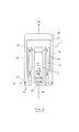
- Fig. 1 shows a general diagram of the reactor 1 according to the invention.
- the reactor 1 comprises a shell 2 with a vertical axis 3 and an inner shell 4 which is open at the top and bottom.
- Said shell 4 preferably is cylindrical with a vertical axis, like the outer shell 2. More advantageously, said shell 4 is coaxial with the shell 2, i.e. has the same vertical axis 3.
- Said inner shell 4 defines a chamber 5 inside which at least one sonication waves source 6 is installed.
- the reactor 1 contains a liquid phase which recirculates through the chamber 5 and in this way is subjected to the action of the sound waves emitted by said source 6.
- the arrows 7 in Fig. 1 indicate the recirculation of the liquid; owing to said recirculation, the substantially entire liquid mass contained inside the reactor 1 is subjected to the sonication process, notwithstanding the volume of the chamber 5 is significantly smaller than the internal volume of the reactor 1.
- Fig. 2 shows in greater detail an embodiment of the invention applied to melamine reactors. For the sake of simplicity, the details which are similar to those of Fig. 1 are indicated with the same reference numbers.
- the wall (or tube) 4 defines a central chamber 5 which forms the primary reaction zone fed with the urea melt 10 via a duct 11.
- Heating elements 13, for example tubes, are housed inside said recirculation chamber 12.
- the reactor in Fig. 2 comprises a further shell 14 delimiting an outer wall of the recirculation chamber 12 and also defining a secondary reaction chamber 15, between the shells 2 and 14, fed with gaseous ammonia 16 via a toroidal distributor 17 located on the bottom of said chamber.
- the top part of the reactor comprises a top-end chamber 18 which collects the gases released inside the chambers 5, 12 and 15, mainly comprising NH 3 and CO 2 . Said gases form a stream 19 of offgases which is carried away towards a scrubber.
- the sound waves source 6 is situated preferably inside the central chamber 5. In this way the sonication affects the liquid phase which recirculates inside the chamber 5, mixing with the urea melt 10.
- the reactor according to Fig. 2 operates in the following manner.
- the liquid melamine circulates with an ascending movement inside the reaction zone 5 and with a descending movement inside the recirculating zone 12, which is also heated by the action of the bodies 13.
- a recirculation in the direction of the arrows shown in the figures is thus created. It should be noted that, owing to the recirculating movement, the sonication affects all the liquid mass recirculating in the reactor, despite the fact that the source 6 is located only in a specific zone, i.e. inside the primary zone 5 which is directly fed with the urea melt 10.
- the liquid melamine reaches the level indicated in the figure by the line 20 and flows over the top edge of the shell 14, passing into the peripheral chamber 15. Inside said chamber 15, the liquid melamine undergoes stripping owing to the counter-flow of gaseous ammonia 16 fed from the toroidal distributor 17.
- the stripped melamine 21 is collected at the bottom of said chamber 15; the gases released during the process - which contain CO 2 and ammonia - are collected in the top chamber 18 and discharged from the line 19 towards a scrubber.
- the sound waves source may be located inside the recirculation chamber 12.
- the sound waves source 6 may be of the electronical or mechanical type. Said source may be formed, in an equivalent manner, with a plurality of sources.
- Fig. 2 shows a melamine reactor which comprises internally the primary reaction zone, inside the central chamber 5 and the recirculation chamber 12, and the secondary or stripping reaction zone, inside the annular chamber 15.
- the invention is also applicable to conventional reactors which comprise only the primary reaction zone. In this case, stripping with ammonia is performed in an external reactor.
- the scrubber of the offgases 19 may be incorporated in the same reactor, for example incorporated in the top part of the reactor 1.
Landscapes
- Chemical & Material Sciences (AREA)
- Organic Chemistry (AREA)
- Chemical Kinetics & Catalysis (AREA)
- Health & Medical Sciences (AREA)
- General Health & Medical Sciences (AREA)
- Toxicology (AREA)
- Organic Low-Molecular-Weight Compounds And Preparation Thereof (AREA)
Priority Applications (14)
| Application Number | Priority Date | Filing Date | Title |
|---|---|---|---|
| EP15161665.3A EP3075725A1 (de) | 2015-03-30 | 2015-03-30 | Ultraschall in einem harnstoff- oder melaminsyntheseverfahren |
| AU2016239601A AU2016239601B2 (en) | 2015-03-30 | 2016-03-11 | Sonication in a urea or melamine synthesis process |
| MYPI2017703341A MY191877A (en) | 2015-03-30 | 2016-03-11 | Sonication in a urea or melamine synthesis process |
| EP16712266.2A EP3277661B1 (de) | 2015-03-30 | 2016-03-11 | Ultraschall in einem harnstoff- oder melaminsyntheseverfahren |
| MX2017012306A MX379700B (es) | 2015-03-30 | 2016-03-11 | Sonicación en un proceso de síntesis de urea o melamina. |
| US15/563,460 US10507451B2 (en) | 2015-03-30 | 2016-03-11 | Sonication in a urea or melamine synthesis process |
| PCT/EP2016/055264 WO2016156015A1 (en) | 2015-03-30 | 2016-03-11 | Sonication in a urea or melamine synthesis process |
| RU2017133799A RU2718901C2 (ru) | 2015-03-30 | 2016-03-11 | Ультразвуковая обработка в процессе синтеза мочевины или меламина |
| CA2978218A CA2978218A1 (en) | 2015-03-30 | 2016-03-11 | Sonication in a urea or melamine synthesis process |
| UAA201710327A UA120533C2 (uk) | 2015-03-30 | 2016-03-11 | Ультразвукова обробка в процесі синтезу сечовини або меламіну |
| BR112017021048-7A BR112017021048B1 (pt) | 2015-03-30 | 2016-03-11 | Sonicaçâo em um processo de síntese de uréia ou de melamina |
| CN201680020198.7A CN107428679B (zh) | 2015-03-30 | 2016-03-11 | 声处理用于尿素或三聚氰胺合成方法 |
| SA517390002A SA517390002B1 (ar) | 2015-03-30 | 2017-09-21 | الصوتنة في عملية تخليق يوريا أو ميلامين |
| CL2017002440A CL2017002440A1 (es) | 2015-03-30 | 2017-09-28 | Sonicación en un proceso de síntesis de urea o melamina |
Applications Claiming Priority (1)
| Application Number | Priority Date | Filing Date | Title |
|---|---|---|---|
| EP15161665.3A EP3075725A1 (de) | 2015-03-30 | 2015-03-30 | Ultraschall in einem harnstoff- oder melaminsyntheseverfahren |
Publications (1)
| Publication Number | Publication Date |
|---|---|
| EP3075725A1 true EP3075725A1 (de) | 2016-10-05 |
Family
ID=53181046
Family Applications (2)
| Application Number | Title | Priority Date | Filing Date |
|---|---|---|---|
| EP15161665.3A Withdrawn EP3075725A1 (de) | 2015-03-30 | 2015-03-30 | Ultraschall in einem harnstoff- oder melaminsyntheseverfahren |
| EP16712266.2A Not-in-force EP3277661B1 (de) | 2015-03-30 | 2016-03-11 | Ultraschall in einem harnstoff- oder melaminsyntheseverfahren |
Family Applications After (1)
| Application Number | Title | Priority Date | Filing Date |
|---|---|---|---|
| EP16712266.2A Not-in-force EP3277661B1 (de) | 2015-03-30 | 2016-03-11 | Ultraschall in einem harnstoff- oder melaminsyntheseverfahren |
Country Status (13)
| Country | Link |
|---|---|
| US (1) | US10507451B2 (de) |
| EP (2) | EP3075725A1 (de) |
| CN (1) | CN107428679B (de) |
| AU (1) | AU2016239601B2 (de) |
| BR (1) | BR112017021048B1 (de) |
| CA (1) | CA2978218A1 (de) |
| CL (1) | CL2017002440A1 (de) |
| MX (1) | MX379700B (de) |
| MY (1) | MY191877A (de) |
| RU (1) | RU2718901C2 (de) |
| SA (1) | SA517390002B1 (de) |
| UA (1) | UA120533C2 (de) |
| WO (1) | WO2016156015A1 (de) |
Citations (6)
| Publication number | Priority date | Publication date | Assignee | Title |
|---|---|---|---|---|
| WO2001030748A1 (en) * | 1999-10-26 | 2001-05-03 | Dsm N.V. | Process for the preparation of urea |
| US6815545B2 (en) | 2000-10-20 | 2004-11-09 | Agrolinz Melamin Gmbh | Method for producing melamine |
| WO2005102992A1 (en) * | 2004-04-22 | 2005-11-03 | Dsm Ip Assets B.V. | Process for the preparation of urea from carbon dioxide and ammonia in a urea plant |
| US7041822B2 (en) | 2001-12-12 | 2006-05-09 | Ami - Agrolinz Melamine International Gmbh | Method for purifying a melamine melt |
| KR20090029375A (ko) * | 2007-09-18 | 2009-03-23 | 주식회사 효성 | 초음파처리시스템 및 2단계로 구성된 초음파처리시스템을통한 5-오르토-톨릴펜텐의 제조방법 |
| WO2011161215A1 (en) | 2010-06-24 | 2011-12-29 | Borealis Agrolinz Melamine Gmbh | Horizontal high-pressure melamine reactor |
Family Cites Families (12)
| Publication number | Priority date | Publication date | Assignee | Title |
|---|---|---|---|---|
| US3325386A (en) * | 1963-12-18 | 1967-06-13 | Jurschewitz Paul Arth Woldemar | Polymerization process using ultrasonic virbrations |
| AT389235B (de) * | 1987-05-19 | 1989-11-10 | Stuckart Wolfgang | Verfahren zur reinigung von fluessigkeiten mittels ultraschall und vorrichtungen zur durchfuehrung dieses verfahrens |
| ES2110449T3 (es) * | 1991-01-15 | 1998-02-16 | Urea Casale Sa | Procedimiento y dispositivo para aumentar el rendimiento y la capacidad de produccion de los reactores de urea. |
| IL144638A (en) * | 2001-07-30 | 2005-12-18 | Nano Size Ltd | High power ultrasound reactor for the production of nano-powder materials |
| NL1021637C2 (nl) * | 2002-07-29 | 2004-01-30 | Dsm Nv | Werkwijze voor het vergroten van de capaciteit van een ureumfabriek. |
| US7160516B2 (en) * | 2002-07-30 | 2007-01-09 | Sonics & Materials, Inc. | High volume ultrasonic flow cell |
| RU2252070C1 (ru) * | 2004-06-16 | 2005-05-20 | Общество с ограниченной ответственностью "Астор-С" | Способ обработки жидкостей в кавитационном реакторе |
| CN201053003Y (zh) * | 2007-06-08 | 2008-04-30 | 王庆仁 | 一种旋笛式低频声波尿素合成塔内粉尘聚合、防粘壁装置 |
| ITMI20072206A1 (it) * | 2007-11-21 | 2009-05-22 | Snam Progetti | Metodo per il recupero di ammoniaca da una corrente gassosa in un processo di sintesi di urea |
| US20090166177A1 (en) * | 2007-12-28 | 2009-07-02 | Kimberly-Clark Worldwide, Inc. | Ultrasonic treatment chamber for preparing emulsions |
| CN102557174B (zh) * | 2012-01-06 | 2013-08-14 | 长沙华时捷环保科技发展有限公司 | 用氨氮废水处理装置降解处理氨氮废水的方法 |
| CN103601693A (zh) * | 2013-10-23 | 2014-02-26 | 李东田 | 氨气循环作载气的一步法三聚氰胺生产方法 |
-
2015
- 2015-03-30 EP EP15161665.3A patent/EP3075725A1/de not_active Withdrawn
-
2016
- 2016-03-11 CN CN201680020198.7A patent/CN107428679B/zh not_active Expired - Fee Related
- 2016-03-11 AU AU2016239601A patent/AU2016239601B2/en not_active Ceased
- 2016-03-11 MX MX2017012306A patent/MX379700B/es unknown
- 2016-03-11 CA CA2978218A patent/CA2978218A1/en active Pending
- 2016-03-11 RU RU2017133799A patent/RU2718901C2/ru active
- 2016-03-11 BR BR112017021048-7A patent/BR112017021048B1/pt not_active IP Right Cessation
- 2016-03-11 UA UAA201710327A patent/UA120533C2/uk unknown
- 2016-03-11 US US15/563,460 patent/US10507451B2/en not_active Expired - Fee Related
- 2016-03-11 MY MYPI2017703341A patent/MY191877A/en unknown
- 2016-03-11 EP EP16712266.2A patent/EP3277661B1/de not_active Not-in-force
- 2016-03-11 WO PCT/EP2016/055264 patent/WO2016156015A1/en not_active Ceased
-
2017
- 2017-09-21 SA SA517390002A patent/SA517390002B1/ar unknown
- 2017-09-28 CL CL2017002440A patent/CL2017002440A1/es unknown
Patent Citations (6)
| Publication number | Priority date | Publication date | Assignee | Title |
|---|---|---|---|---|
| WO2001030748A1 (en) * | 1999-10-26 | 2001-05-03 | Dsm N.V. | Process for the preparation of urea |
| US6815545B2 (en) | 2000-10-20 | 2004-11-09 | Agrolinz Melamin Gmbh | Method for producing melamine |
| US7041822B2 (en) | 2001-12-12 | 2006-05-09 | Ami - Agrolinz Melamine International Gmbh | Method for purifying a melamine melt |
| WO2005102992A1 (en) * | 2004-04-22 | 2005-11-03 | Dsm Ip Assets B.V. | Process for the preparation of urea from carbon dioxide and ammonia in a urea plant |
| KR20090029375A (ko) * | 2007-09-18 | 2009-03-23 | 주식회사 효성 | 초음파처리시스템 및 2단계로 구성된 초음파처리시스템을통한 5-오르토-톨릴펜텐의 제조방법 |
| WO2011161215A1 (en) | 2010-06-24 | 2011-12-29 | Borealis Agrolinz Melamine Gmbh | Horizontal high-pressure melamine reactor |
Non-Patent Citations (3)
| Title |
|---|
| "Ullmann's Encyclopedia of Industrial Chemistry", vol. 21, pages: 205 |
| "Ullmann's Encyclopedia of Industrial Chemistry", vol. A27, WILEY-VCH VERLAG |
| DATABASE WPI Week 200933, Derwent World Patents Index; AN 2009-H17443, XP002744399 * |
Also Published As
| Publication number | Publication date |
|---|---|
| CN107428679A (zh) | 2017-12-01 |
| AU2016239601A1 (en) | 2017-09-21 |
| US10507451B2 (en) | 2019-12-17 |
| UA120533C2 (uk) | 2019-12-26 |
| RU2017133799A (ru) | 2019-05-06 |
| RU2718901C2 (ru) | 2020-04-15 |
| US20180071708A1 (en) | 2018-03-15 |
| AU2016239601B2 (en) | 2020-08-06 |
| RU2017133799A3 (de) | 2019-05-06 |
| BR112017021048B1 (pt) | 2020-11-17 |
| CN107428679B (zh) | 2020-09-01 |
| MX2017012306A (es) | 2017-12-14 |
| EP3277661B1 (de) | 2018-12-12 |
| CA2978218A1 (en) | 2016-10-06 |
| CL2017002440A1 (es) | 2018-03-16 |
| MX379700B (es) | 2025-03-11 |
| WO2016156015A1 (en) | 2016-10-06 |
| MY191877A (en) | 2022-07-18 |
| EP3277661A1 (de) | 2018-02-07 |
| SA517390002B1 (ar) | 2021-06-07 |
| BR112017021048A2 (pt) | 2018-07-03 |
Similar Documents
| Publication | Publication Date | Title |
|---|---|---|
| US9505712B2 (en) | Method and apparatus for the production of urea from ammonia and carbon dioxide | |
| US10501407B2 (en) | Urea manufacturing method and urea manufacturing apparatus | |
| US20180304227A1 (en) | Synthesis of organic peroxydes using an oscillatory flow mixing reactor | |
| CN1130354C (zh) | 蜜胺生产的方法和设备 | |
| EP3429989B1 (de) | Kombinierte vorrichtung für die synthese von harnstoff | |
| CN113710341A (zh) | 在尿素设备中使用的高压汽提器 | |
| RU2664069C2 (ru) | Комбинированный реактор для синтеза меламина при высоком давлении | |
| CN112456450B (zh) | 一种含有机物废硫酸资源化利用的系统和方法 | |
| EP3277661B1 (de) | Ultraschall in einem harnstoff- oder melaminsyntheseverfahren | |
| CN106102894B (zh) | 用于合成三聚氰胺的高压反应器及方法 | |
| PL100430B1 (pl) | Sposob wytwarzania mocznika z amoniaku i dwutlenku wegla | |
| AU2016311013A1 (en) | A reactor-condenser for the synthesis of urea | |
| JP4925276B2 (ja) | ミキサセトラ型ブンゼン反応器 | |
| SU558443A1 (ru) | Реактор | |
| RU2146653C1 (ru) | Трубчатый реактор для проведения экзотермических реакций и способ получения нитрата аммония в нем | |
| RU157330U1 (ru) | Многотрубный реактор для проведения химических реакций при сверхкритических параметрах водной среды | |
| RU157328U1 (ru) | Многотрубный реактор для проведения химических реакций при сверхкритических параметрах водной среды | |
| EA048170B1 (ru) | Химический реактор с внутренними статическими смесителями | |
| RU2024114409A (ru) | Устройство струйного эжектора, система, их применение и способ работы | |
| RU2008129728A (ru) | Способ управления температурой экзотермических химических реакций | |
| WO2020027702A3 (en) | Apparatus and method for plasma-chemical hydrocracking, and plant with such apparatus |
Legal Events
| Date | Code | Title | Description |
|---|---|---|---|
| PUAI | Public reference made under article 153(3) epc to a published international application that has entered the european phase |
Free format text: ORIGINAL CODE: 0009012 |
|
| AK | Designated contracting states |
Kind code of ref document: A1 Designated state(s): AL AT BE BG CH CY CZ DE DK EE ES FI FR GB GR HR HU IE IS IT LI LT LU LV MC MK MT NL NO PL PT RO RS SE SI SK SM TR |
|
| AX | Request for extension of the european patent |
Extension state: BA ME |
|
| STAA | Information on the status of an ep patent application or granted ep patent |
Free format text: STATUS: THE APPLICATION IS DEEMED TO BE WITHDRAWN |
|
| 18D | Application deemed to be withdrawn |
Effective date: 20170406 |