EP3075979B1 - Motor - Google Patents
Motor Download PDFInfo
- Publication number
- EP3075979B1 EP3075979B1 EP14856433.9A EP14856433A EP3075979B1 EP 3075979 B1 EP3075979 B1 EP 3075979B1 EP 14856433 A EP14856433 A EP 14856433A EP 3075979 B1 EP3075979 B1 EP 3075979B1
- Authority
- EP
- European Patent Office
- Prior art keywords
- exhaust
- engine
- supercharger
- exhaust manifolds
- valve
- Prior art date
- Legal status (The legal status is an assumption and is not a legal conclusion. Google has not performed a legal analysis and makes no representation as to the accuracy of the status listed.)
- Not-in-force
Links
Images





Classifications
-
- F—MECHANICAL ENGINEERING; LIGHTING; HEATING; WEAPONS; BLASTING
- F02—COMBUSTION ENGINES; HOT-GAS OR COMBUSTION-PRODUCT ENGINE PLANTS
- F02B—INTERNAL-COMBUSTION PISTON ENGINES; COMBUSTION ENGINES IN GENERAL
- F02B37/00—Engines characterised by provision of pumps driven at least for part of the time by exhaust
- F02B37/02—Gas passages between engine outlet and pump drive, e.g. reservoirs
- F02B37/025—Multiple scrolls or multiple gas passages guiding the gas to the pump drive
-
- F—MECHANICAL ENGINEERING; LIGHTING; HEATING; WEAPONS; BLASTING
- F02—COMBUSTION ENGINES; HOT-GAS OR COMBUSTION-PRODUCT ENGINE PLANTS
- F02B—INTERNAL-COMBUSTION PISTON ENGINES; COMBUSTION ENGINES IN GENERAL
- F02B37/00—Engines characterised by provision of pumps driven at least for part of the time by exhaust
- F02B37/12—Control of the pumps
- F02B37/22—Control of the pumps by varying cross-section of exhaust passages or air passages, e.g. by throttling turbine inlets or outlets or by varying effective number of guide conduits
-
- F—MECHANICAL ENGINEERING; LIGHTING; HEATING; WEAPONS; BLASTING
- F01—MACHINES OR ENGINES IN GENERAL; ENGINE PLANTS IN GENERAL; STEAM ENGINES
- F01N—GAS-FLOW SILENCERS OR EXHAUST APPARATUS FOR MACHINES OR ENGINES IN GENERAL; GAS-FLOW SILENCERS OR EXHAUST APPARATUS FOR INTERNAL-COMBUSTION ENGINES
- F01N13/00—Exhaust or silencing apparatus characterised by constructional features
- F01N13/08—Other arrangements or adaptations of exhaust conduits
- F01N13/10—Other arrangements or adaptations of exhaust conduits of exhaust manifolds
- F01N13/107—More than one exhaust manifold or exhaust collector
-
- F—MECHANICAL ENGINEERING; LIGHTING; HEATING; WEAPONS; BLASTING
- F02—COMBUSTION ENGINES; HOT-GAS OR COMBUSTION-PRODUCT ENGINE PLANTS
- F02B—INTERNAL-COMBUSTION PISTON ENGINES; COMBUSTION ENGINES IN GENERAL
- F02B37/00—Engines characterised by provision of pumps driven at least for part of the time by exhaust
- F02B37/004—Engines characterised by provision of pumps driven at least for part of the time by exhaust with exhaust drives arranged in series
-
- F—MECHANICAL ENGINEERING; LIGHTING; HEATING; WEAPONS; BLASTING
- F02—COMBUSTION ENGINES; HOT-GAS OR COMBUSTION-PRODUCT ENGINE PLANTS
- F02B—INTERNAL-COMBUSTION PISTON ENGINES; COMBUSTION ENGINES IN GENERAL
- F02B37/00—Engines characterised by provision of pumps driven at least for part of the time by exhaust
- F02B37/013—Engines characterised by provision of pumps driven at least for part of the time by exhaust with exhaust-driven pumps arranged in series
-
- F—MECHANICAL ENGINEERING; LIGHTING; HEATING; WEAPONS; BLASTING
- F01—MACHINES OR ENGINES IN GENERAL; ENGINE PLANTS IN GENERAL; STEAM ENGINES
- F01N—GAS-FLOW SILENCERS OR EXHAUST APPARATUS FOR MACHINES OR ENGINES IN GENERAL; GAS-FLOW SILENCERS OR EXHAUST APPARATUS FOR INTERNAL-COMBUSTION ENGINES
- F01N2240/00—Combination or association of two or more different exhaust treating devices, or of at least one such device with an auxiliary device, not covered by indexing codes F01N2230/00 or F01N2250/00, one of the devices being
- F01N2240/36—Combination or association of two or more different exhaust treating devices, or of at least one such device with an auxiliary device, not covered by indexing codes F01N2230/00 or F01N2250/00, one of the devices being an exhaust flap
-
- F—MECHANICAL ENGINEERING; LIGHTING; HEATING; WEAPONS; BLASTING
- F01—MACHINES OR ENGINES IN GENERAL; ENGINE PLANTS IN GENERAL; STEAM ENGINES
- F01N—GAS-FLOW SILENCERS OR EXHAUST APPARATUS FOR MACHINES OR ENGINES IN GENERAL; GAS-FLOW SILENCERS OR EXHAUST APPARATUS FOR INTERNAL-COMBUSTION ENGINES
- F01N2590/00—Exhaust or silencing apparatus adapted to particular use, e.g. for military applications, airplanes, submarines
- F01N2590/02—Exhaust or silencing apparatus adapted to particular use, e.g. for military applications, airplanes, submarines for marine vessels or naval applications
-
- Y—GENERAL TAGGING OF NEW TECHNOLOGICAL DEVELOPMENTS; GENERAL TAGGING OF CROSS-SECTIONAL TECHNOLOGIES SPANNING OVER SEVERAL SECTIONS OF THE IPC; TECHNICAL SUBJECTS COVERED BY FORMER USPC CROSS-REFERENCE ART COLLECTIONS [XRACs] AND DIGESTS
- Y02—TECHNOLOGIES OR APPLICATIONS FOR MITIGATION OR ADAPTATION AGAINST CLIMATE CHANGE
- Y02T—CLIMATE CHANGE MITIGATION TECHNOLOGIES RELATED TO TRANSPORTATION
- Y02T10/00—Road transport of goods or passengers
- Y02T10/10—Internal combustion engine [ICE] based vehicles
- Y02T10/12—Improving ICE efficiencies
Definitions
- the present invention relates to an engine.
- the present invention relates to an engine with a supercharger.
- an engine in which exhaust manifolds communicate with each other via an on/off valve in order to improve fuel consumption in a case where the engine is in a high speed region is publicly known.
- This engine is configured such that dynamic pressure supercharging exhaust manifolds can be changed to static pressure exhaust manifolds by bringing the on/off valve into an opened state. Accordingly, in the engine, by providing communication between the exhaust manifolds and increasing an actual pipe diameter, fuel consumption deterioration due to thermal losses can be suppressed. For example, this is as described in Patent Document 1.
- Patent Document 1 In an engine described in Patent Document 1, in order to switch dynamic pressure supercharging exhaust manifolds to static pressure supercharging exhaust manifolds, a communication pipe providing communication between the exhaust manifolds and an on/off valve are required.
- the communication pipe and the on/off valve enabling switching of the dynamic pressure supercharging method and a static pressure supercharging method are disadvantageously excessive facilities and a cause for increasing cost.
- Patent Literature 2 turbo-driven superchargers for two-stroke I.C. engines are disclosed.
- a receiver In a supercharged engine having the turbine of an exhaust driven turbocharger connected to a group of cylinders by a short conduit, a receiver is connected to the pipe by a shut off valve. At starting and low loads valve is closed and turbine operates on the pulse system. At higher loads the valve is opened, whereby the receiver damps pulsations and the turbine operates on the constant pressure system.
- Separate groups of cylinders 1...3, and 4...6 are connected by pipes to separate turbines, and the receiver is connected to both conduits through valves.
- the turbochargers deliver through coolers to opposite ends of the charge receiver.
- Patent Literature 3 an engine exhaust system is disclosed.
- the engine exhaust system comprise a first exhaust passage and a second exhaust passage connected with a separate combustion chamber of the engine and guiding the exhaust gas independently to the twin scroll type supercharger, a connection passage to put the exhaust passages in mutual communication, a communication control valve installed in the connection passage in such a way as capable of being opened and closed, and a control part to open the control valve when the engine is in a high speed operation and close the valve when the engine is in a low speed operation, wherein the pressure pulsations in the exhaust gases in the exhaust passages are made uniform when the engine is in the high speed operation.
- the present invention is achieved in consideration of the above situation, and an object thereof is to provide an engine in which without replacing exhaust manifolds themselves, the exhaust manifolds capable of switching a dynamic pressure supercharging method and a static pressure supercharging method can be easily changed to the exhaust manifolds only of the dynamic pressure supercharging method or only of the static pressure supercharging method.
- the coupling pipes include a bent pipe and an on/off valve that brings the exhaust manifolds into an independent state is provided in each of the coupling pipes, and the coupling pipe is configured such that a part including the on/off valve or the on/off valve is attached to the exhaust manifolds.
- the present invention is characterized in that the coupling pipes coupling the exhaust manifolds are coupled to each other via one or more branch pipes.
- the number of the plurality of provided independent exhaust manifolds is three or more
- a first reference value and a second reference value in a load factor of the engine are set depending on rotation speed of the engine, in a case where the load factor is less than the first reference value, all the on/off valves are brought into a closed state, in a case where the load factor is the first reference value or more and less than the second reference value, some of the on/off valves are brought into an opened state, and in a case where the load factor is the second reference value or more, all the on/off valves are brought into an opened state.
- all the on/off valves may be brought into a closed state, and in a case where the increase/decrease amount of the load factor per unit time becomes and is kept at less than the predetermined value for a predetermined period of time, the on/off valves may be opened and closed depending on the load factor.
- the coupling pipe including the on/off valve or only the on/off valve is easily attached to and detached from the exhaust manifolds. Accordingly, without replacing the exhaust manifolds themselves, the exhaust manifolds capable of switching a dynamic pressure supercharging method and a static pressure supercharging method can be easily changed to the exhaust manifolds only of the dynamic pressure supercharging method or only of the static pressure supercharging method.
- the coupling pipe is disposed and concentrated on one side end parts of the exhaust manifolds. Accordingly, in the engine, the exhaust manifolds capable of switching the dynamic pressure supercharging method and the static pressure supercharging method can be formed with a configuration in which attachment and detachment of the coupling pipe and maintenance of the on/off valve are easily performed.
- a pressure state of the exhaust air supplied to the supercharger is changed based on the load factor of the engine. Accordingly, responsiveness of the supercharger at the time of low-speed rotation of the supercharger and fuel consumption of the engine at the time of high-speed rotation of the supercharger can be improved.
- the responsiveness of the supercharger is improved. Accordingly, generation of black smoke at the time of a transient response can be suppressed and the fuel consumption can also be improved.
- a vessel 100 serving as a first embodiment of a vessel in which an engine 1 including a supercharger 3 according to the present invention is mounted will be described with reference to Fig. 1 .
- the vessel 100 includes a vessel body 101, a bridge 102, an engine room 103, a propeller 104, and a helm 108.
- the bridge 102 having a control cabin and the like is provided in an upper part of the vessel body 101.
- the engine room 103 is provided in a rear part of the vessel body 101.
- a main engine 105 serving as an internal combustion engine that drives the propeller 104
- an auxiliary engine 106 serving as an internal combustion engine that drives a generator 107 are provided.
- the propeller 104 and the helm 108 are provided at the stern of the vessel body 101.
- the vessel 100 is configured such that power of the main engine 105 can be transmitted to the propeller 104 via a propeller shaft 104a.
- the main engine 105 and the auxiliary engine 106 are configured by the engine 1 which is a diesel engine whose fuel is light oil or heavy oil.
- the engine 1 is a diesel engine whose fuel is light oil or heavy oil.
- an output shaft is driven and rotated by mixing and combusting the outside air and the fuel. It should be noted that the engine 1 is not limited to the diesel engine.
- the engine 1 is the diesel engine, and in the present embodiment, an in-line six-cylinder engine which has six cylinders.
- the engine is an in-line six-cylinder engine including a single-stage supercharger.
- the present invention is not limited to this but the engine may be a multicylinder engine including one or more supercharger.
- the output shaft is driven and rotated by mixing and combusting the outside air and the fuel inside the cylinders.
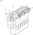
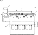
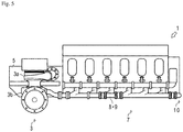
- the engine 1 includes an intake device 2 that takes the outside air in, and an exhaust device 7 that discharges the exhaust air to the outside.
- the intake device 2 includes a compressor portion 3a of the supercharger 3, an air supply pipe 4, an intercooler 5, and an air supply manifold 6.
- the supercharger 3 is to pressurize and compress the intake air with exhaust pressure of the exhaust air as a drive source.
- the supercharger 3 includes the compressor portion 3a and a turbine portion 3b.
- the compressor portion 3a of the supercharger 3 is to pressurize and compress the intake air.
- the compressor portion 3a is coupled to the turbine portion 3b by a coupling shaft 3c.
- the compressor portion 3a is configured such that rotation power from the turbine portion 3b can be transmitted via the coupling shaft 3c.
- the intercooler 5 is connected to the compressor portion 3a via the air supply pipe 4.
- the intercooler 5 is to cool the pressurized intake air. By performing heat exchange between cooling water supplied by a cooling water pump (not shown) and the pressurized intake air (hereinafter, the intake air pressurized and compressed by the compressor portion 3a will be referred to as the supplied air), the intercooler 5 cools the supplied air.
- the air supply manifold 6 is connected to the intercooler 5.
- the air supply manifold 6 is to distribute the supplied air to the cylinders of the engine 1.
- the air supply manifold 6 is connected to the cylinders of the engine 1.
- the air supply manifold 6 is configured such that the supplied air cooled in the intercooler 5 can be supplied to the cylinders of the engine 1.
- the exhaust device 7 includes exhaust manifolds 8, 9, and the turbine portion 3b of the supercharger 3.
- the exhaust manifolds 8, 9 are respectively independently connected to two cylinder groups including cylinders of the same phase of the engine 1 (a group of first, fourth, and fifth cylinders, and a group of second, third, and sixth cylinders in the present embodiment). That is, the exhaust manifold 8 discharges the exhaust air from the first, fourth, and fifth cylinders together, and the exhaust manifold 9 discharges the exhaust air from the second, third, and sixth cylinders together.
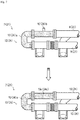
- a coupling pipe 10 (refer to a hatched part in Fig. 6 ) is detachably coupled to end parts (one side end parts) of the exhaust manifolds 8, 9.
- the supercharger 3 is connected to the other side end parts of the exhaust manifolds 8, 9.
- the coupling pipe 10 includes a bent pipe 10a, an on/off valve 10b, and an extension pipe 10c.
- the coupling pipe 10 is detachable from the exhaust manifolds 8, 9. With such a configuration, the coupling pipe 10 is formed so as to couple the independent exhaust manifolds 8, 9 to each other.
- the one side end parts of the exhaust manifolds 8, 9 are coupled to each other by the coupling pipe 10. That is, since the coupling pipe 10 is disposed to the one side end parts of the exhaust manifolds 8, 9, in the exhaust device 7, the exhaust manifolds 8, 9 capable of switching a dynamic pressure supercharging method and a static pressure supercharging method can be formed with a configuration in which attachment and detachment of the coupling pipe 10 and maintenance of the on/off valve 10b are easily performed.
- the turbine portion 3b of the supercharger 3 is to generate the rotation power by the pressure of the exhaust air.
- the turbine portion 3b is coupled to the compressor portion 3a by the coupling shaft 3c, and is configured such that the rotation power can be transmitted to the compressor portion 3a.
- the exhaust manifolds 8, 9 are connected to the turbine portion 3b.
- the turbine portion 3b communicates with the outside via a purifying device (not shown) or the like.
- the compressor portion 3a of the supercharger 3, the air supply pipe 4, the intercooler 5, and the air supply manifold 6 are connected in order from the upstream side (outside).
- the exhaust manifolds 8, 9, the turbine portion 3b of the supercharger 3, and an exhaust pipe or the like are connected in order from the upstream side (engine 1).
- the intercooler 5 is fixed to a side surface in one side end part in the axial direction of an output axis A of the engine 1.
- the supercharger 3 is fixed to an upper part of the intercooler 5. That is, in the engine 1, the supercharger 3 and the intercooler 5 are disposed in the one side end part in the axial direction of the output axis A.
- the air supply manifold 6 is formed in an engine block of the engine 1 on one side of the direction orthogonal to the output axis A on a horizontal plane.
- the air supply manifold 6 is configured so as to communicate with the intercooler 5 fixed to the side surface in the one side end part of the engine 1.
- the exhaust manifolds 8, 9 are disposed on the other side of the direction orthogonal to the output axis A of the engine 1 on the horizontal plane.
- the exhaust manifold 9 is disposed in line with the exhaust manifold 8 on the lower side of the exhaust manifold 8.
- the intake air is taken in, pressurized, and compressed by the compressor portion 3a of the supercharger 3.
- intake air is taken in, pressurized, and compressed by the compressor portion 3a of the supercharger 3.
- compression heat is generated and a temperature is increased.
- the intake air pressurized and compressed in the compressor portion 3a is discharged from the supercharger 3.
- the intake air discharged from the supercharger 3 is supplied to the intercooler 5 via the air supply pipe 4.
- the intake air supplied to the intercooler 5 is cooled and then supplied to the engine 1 via the air supply manifold 6.
- the exhaust air from the engine 1 is supplied to the turbine portion 3b of the supercharger 3 via the exhaust manifold 8 and the exhaust manifold 9.
- the turbine portion 3b is rotated by the exhaust air.
- the rotation power of the turbine portion 3b is transmitted to the compressor portion 3a via the coupling shaft 3c.
- the exhaust air supplied to the turbine portion 3b is discharged to the outside via the purifying device (not shown) or the like.
- Figs. 6 and 7 represent one side parts of the exhaust manifolds 8, 9 of the engine 1.
- the coupling pipe 10 (hatched part) is detachably coupled to the end parts (one side end parts) of the exhaust manifolds 8, 9, the end parts on the opposite side of the supercharger 3.
- the supercharger 3 is connected to the other side end parts of the exhaust manifolds 8, 9 (refer to Figs. 2 to 5 ).
- the coupling pipe 10 is to couple the exhaust manifold 8 and the exhaust manifold 9.
- the coupling pipe 10 includes the bent pipe 10a, the on/off valve 10b, or the extension pipe 10c.
- the coupling pipe 10 is detachable from the one side end parts of the exhaust manifolds 8, 9.
- the coupling pipe 10 is formed so as to switch whether or not the exhaust manifold 8 and the exhaust manifold 9 communicate with each other by a state of the on/off valve 10b.
- the coupling pipe 10 is configured such that the extension pipe 10c can be connected instead of the on/off valve 10b. Accordingly, the coupling pipe 10 is formed so as to couple the exhaust manifold 8 and the exhaust manifold 9 without the on/off valve 10b.
- the exhaust manifold 8 and the exhaust manifold 9 are independently connected to the second turbine portion 3b of the supercharger 3. That is, in the exhaust device 7, the exhaust manifolds corresponding to the dynamic pressure supercharging method are formed.
- the exhaust manifold 8 and the exhaust manifold 9 are connected to the turbine portion 3b of the supercharger 3 in a state where the exhaust manifolds communicate with each other. That is, in the exhaust device 7, the exhaust manifolds 8, 9 corresponding to the static pressure supercharging method are formed.
- the coupling pipe 10 is removed from the exhaust manifolds 8, 9 in the exhaust device 7.
- the one side end parts of the exhaust manifolds 8, 9 are sealed by lids 8a, 9a, respectively. Accordingly, in the exhaust device 7, the exhaust manifold 8 and the exhaust manifold 9 are connected to the supercharger 3 in a state where the exhaust manifolds are independent from each other. That is, in the exhaust device 7, the exhaust manifolds 8, 9 corresponding only to the dynamic pressure supercharging method are formed.
- the on/off valve 10b is removed from the coupling pipe 10 and instead, the extension pipe 10c is attached in the exhaust device 7. Accordingly, in the exhaust device 7, the exhaust manifold 8 and the exhaust manifold 9 are connected to the supercharger 3 in a state where the exhaust manifolds communicate with each other. That is, in the exhaust device 7, the exhaust manifolds 8, 9 corresponding only to the static pressure supercharging method are formed.
- the one side end part of the exhaust manifold 8 and the one side end part of the exhaust manifold 9 are coupled by the coupling pipe 10.
- the coupling pipe 10 including the on/off valve 10b or only the on/off valve 10b is easily attached to and detached from the exhaust manifolds 8, 9. Accordingly, without replacing the exhaust manifolds 8, 9, the exhaust manifolds 8, 9 capable of switching the dynamic pressure supercharging method and the static pressure supercharging method can be easily changed to the exhaust manifolds 8, 9 only of the dynamic pressure supercharging method or only of the static pressure supercharging method.
- the engine 11 is a diesel engine, and in the present example, an in-line six-cylinder engine which has six cylinders.
- the engine is an in-line six-cylinder engine including a two-stage supercharger.
- the present invention is not limited to this but the engine may be a multicylinder engine including one or more supercharger.
- an output shaft is driven and rotated by mixing and combusting the outside air and fuel inside the cylinders.
- the engine 11 includes an intake device 12 that takes the outside air in, and an exhaust device 21 that discharges the exhaust air to the outside.
- the intake device 12 includes a first compressor portion 13a of the first supercharger 13, air supply pipes 14, 16, 18, a low pressure side intercooler 15, a second compressor portion 17a of the second supercharger 17, a high pressure side intercooler 19, and an air supply manifold 20.
- the first supercharger 13 serving as a low pressure stage supercharger is to pressurize and compress the intake air with exhaust pressure of the exhaust air as a drive source.
- the supercharger 3 includes the compressor portion 13a and a turbine portion 13b.
- the first compressor portion 13a of the first supercharger 13 is to pressurize and compress the intake air.
- the first compressor portion 13a is coupled to the first turbine portion 13b by a coupling shaft 13c.
- the first compressor portion 13a is configured such that rotation power from the first turbine portion 13b can be transmitted via the coupling shaft 13c.
- the first compressor portion 13a is connected to the low pressure side intercooler 15 via the air supply pipe 14.
- the low pressure side intercooler 15 and the high pressure side intercooler 19 are to cool the intake air. By performing heat exchange between cooling water supplied by a cooling water pump (not shown) and the intake air, the low pressure side intercooler 15 and the high pressure side intercooler 19 cool the intake air.
- the low pressure side intercooler 15 is connected to the second compressor portion 17a via the air supply pipe 16.
- the high pressure side intercooler 19 is connected to the engine 11 via the air supply manifold 20.
- the second supercharger 17 serving as a high pressure stage supercharger is to pressurize and compress the intake air with the exhaust pressure of the exhaust air as a drive source.
- the supercharger 3 includes the second compressor portion 17a and a second turbine portion 17b.
- the second compressor portion 17a of the second supercharger 17 is to pressurize and compress the supplied air.
- the second compressor portion 17a is coupled to the second turbine portion 17b by a coupling shaft 17c.
- the second compressor portion 17a is configured such that rotation power from the second turbine portion 17b can be transmitted via the coupling shaft 17c.
- the second compressor portion 17a is connected to the high pressure side intercooler 19 via the air supply pipe 18.
- the air supply manifold 20 is to distribute the supplied air to the cylinders of the engine 11.
- the air supply manifold 20 is connected to the cylinders of the engine 11.
- the air supply manifold 20 is configured such that the supplied air cooled in the intercooler 5 can be supplied to the cylinders of the engine 1.
- the exhaust device 21 includes exhaust manifolds 22, 23, an exhaust pipe 25, the first turbine portion 13b of the first supercharger 13, and the second turbine portion 17b of the second supercharger 17.
- the exhaust manifolds 22, 23 are respectively independently connected to two cylinder groups including cylinders of the same phase of the engine 11 (a group of first, fourth, and fifth cylinders, and a group of second, third, and sixth cylinders in the present embodiment). That is, the exhaust manifold 22 discharges the exhaust air from the first, fourth, and fifth cylinders together, and the exhaust manifold 23 discharges the exhaust air from the second, third, and sixth cylinders together.
- a coupling pipe 24 (refer to the hatched part in Fig. 6 ) is detachably coupled to end parts (one side end parts) of the exhaust manifolds 22, 23.
- the second supercharger 17 is connected to the other side end parts of the exhaust manifolds 22, 23.
- the coupling pipe 24 includes a bent pipe 24a, an on/off valve 24b, and an extension pipe 24c.
- the coupling pipe 24 is detachable from the exhaust manifolds 22, 23. With such a configuration, the coupling pipe 24 is formed so as to couple the independent exhaust manifolds 22, 23 to each other.
- the first turbine portion 13b of the first supercharger 13 is to generate the rotation power by the pressure of the exhaust air.
- the first turbine portion 13b is coupled to the compressor portion 13a by the coupling shaft 13c, and is configured such that the rotation power can be transmitted to the compressor portion 13a.
- the first turbine portion 13b is configured so as to be rotated by the exhaust air supplied from the second turbine portion 17b of the second supercharger 17 via the exhaust pipe 25.
- the first turbine portion 13b is discharged to the outside via a purifying device (not shown) or the like.
- the second turbine portion 17b of the second supercharger 17 is to generate the rotation power by the pressure of the exhaust air.
- the second turbine portion 17b is coupled to the second compressor portion 17a by the coupling shaft 17c, and is configured such that the rotation power can be transmitted to the second compressor portion 17a.
- the exhaust manifolds 22, 23 are connected to the second turbine portion 17b.
- the second turbine portion 17b is connected to the first turbine portion 13b of the first supercharger 13 via the exhaust pipe 25.
- the first compressor portion 13a, the air supply pipe 14, the low pressure side intercooler 15, the air supply pipe 16, the second compressor portion 17a, the air supply pipe 18, the high pressure side intercooler 19, and the air supply manifold 20 are connected in order from the upstream side (outside).
- the exhaust manifolds 22, 23, the second turbine portion 17b, the exhaust pipe 25, and the first turbine portion 13b are connected in order from the upstream side (engine 11).
- the outside air (intake air) is taken in, pressurized, and compressed by the first compressor portion 13a of the first supercharger 13.
- intake air the outside air
- compression heat is generated and a temperature is increased.
- the intake air pressurized and compressed in the first compressor portion 13a is discharged from the first supercharger 13.
- the intake air discharged from the first supercharger 13 is supplied to the low pressure side intercooler 15 via the air supply pipe 14.
- the intake air supplied to the low pressure side intercooler 15 is cooled and then supplied to the second compressor portion 17a of the second supercharger 17 via the air supply pipe 16.
- the intake air supplied to the second compressor portion 17a of the second supercharger 17 is pressurized and compressed by the second compressor portion 17a. At this time, by pressurization and compression of the intake air, the compression heat is generated and the temperature is increased. The intake air pressurized and compressed in the second compressor portion 17a is discharged from the second supercharger 17.
- the intake air discharged from the second supercharger 17 is supplied to the high pressure side intercooler 19 via the air supply pipe 18.
- the intake air supplied to the high pressure side intercooler 19 is cooled and then supplied to the engine 11 via the air supply manifold 20.
- the exhaust air from the engine 11 is supplied to the second turbine portion 17b of the second supercharger 17 via the exhaust manifold 22 and the exhaust manifold 23.
- the second turbine portion 17b is rotated by the exhaust air.
- the rotation power of the second turbine portion 17b is transmitted to the second compressor portion 17a via the coupling shaft 17c.
- the exhaust air supplied to the second turbine portion 17b is discharged from the second supercharger 17.
- the exhaust air discharged from the second supercharger 17 is supplied to the first turbine portion 13b of the first supercharger 13 via the exhaust pipe 25.
- the first turbine portion 13b is rotated by the exhaust air.
- the rotation power of the first turbine portion 13b is transmitted to the first compressor portion 13a via the coupling shaft 13c.
- the exhaust air supplied to the first turbine portion 13b is discharged to the outside via the exhaust pipe 25, the purifying device (not shown), or the like.
- the low pressure side intercooler 15 is fixed to one side end part of the engine 11 in the axial direction of an output axis A.
- the first supercharger 13 is fixed to an upper part of the low pressure side intercooler 15.
- the high pressure side intercooler 19 is fixed to the other side end part of the engine 11 in the axial direction of the output axis A.
- the second supercharger 17 is fixed to an upper part of the high pressure side intercooler 19.
- the first supercharger 13 and the low pressure side intercooler 15 are disposed in the one side end part in the axial direction of the output axis A, and the second supercharger 17 and the high pressure side intercooler 19 are disposed in the other side end part in the axial direction of the output axis A.
- the air supply pipe 16 connecting the low pressure side intercooler 15 and the second supercharger 17 is disposed on one side of the direction orthogonal to the output axis A of the engine 11 on a horizontal plane.
- the exhaust pipe 25 connecting the second supercharger 17 and the first supercharger 13 is disposed on the other side of the direction orthogonal to the output axis A of the engine 11 on the horizontal plane.
- the air supply pipe 16 is disposed on the opposite side to the exhaust manifolds 22, 23 of the engine 11.
- the exhaust pipe 25 is disposed on the side of the exhaust manifolds 22, 23 of the engine 11. That is, in the engine 11, the air supply pipe 16 and the exhaust pipe 25 are disposed so as to face each other across the engine 11.
- the air supply manifold 20 is disposed in an engine block of the engine 11 on the other side of the direction orthogonal to the output axis A on the horizontal plane.
- the exhaust manifolds 22, 23 are disposed on the other side of the direction orthogonal to the output axis A of the engine 11 on the horizontal plane.
- the exhaust manifolds 22, 23 are disposed between the engine 11 and the exhaust pipe 25.
- the exhaust manifold 23 is disposed in line with the exhaust manifold 22 on the lower side of the exhaust manifold 22.
- Figs. 6 and 7 represent one side parts of the exhaust manifolds 22, 23 of the engine 11.
- the coupling pipe 24 (hatched part) is detachably coupled to the end parts (one side end parts) of the exhaust manifolds 22, 23, the end parts on the side of the first supercharger 13.
- the second supercharger 17 is connected to the other side end parts of the exhaust manifolds 22, 23 (refer to Figs. 8 to 11 ).
- the coupling pipe 24 is to couple the exhaust manifold 22 and the exhaust manifold 23.
- the coupling pipe 24 includes the bent pipe 24a, the on/off valve 24b, and the extension pipe 24c.
- the coupling pipe 24 is detachable from the one side end parts of the exhaust manifolds 22, 23.
- the coupling pipe 24 is formed so as to switch whether or not the exhaust manifold 22 and the exhaust manifold 23 communicate with each other by a state of the on/off valve 24b.
- one side end part of the bent pipe 24a is coupled to the one side end part of the exhaust manifold 23, and the one side end part of the exhaust manifold 22 is coupled to the other side end part of the bent pipe 24a via the on/off valve 24b.
- the coupling pipe 24 is configured such that the extension pipe 24c can be connected instead of the on/off valve 24b. Accordingly, the coupling pipe 24 is formed so as to couple the exhaust manifold 22 and the exhaust manifold 23 without the on/off valve 24b.
- the exhaust manifold 22 and the exhaust manifold 23 are independently connected to the second turbine portion 17b of the second supercharger 17. That is, in the exhaust device 21, the exhaust manifolds corresponding to the dynamic pressure supercharging method are formed.
- the exhaust manifold 22 and the exhaust manifold 23 are connected to the second turbine portion 17b of the second supercharger 17 in a state where the exhaust manifolds communicate with each other. That is, in the exhaust device 21, the exhaust manifolds 22, 23 corresponding to the static pressure supercharging method are formed.
- the coupling pipe 24 is removed from the exhaust manifolds 22, 23 in the exhaust device 21.
- the one side end parts of the exhaust manifolds 22, 23 are sealed by lids 8a, 9a, respectively. Accordingly, in the exhaust device 21, the exhaust manifold 22 and the exhaust manifold 23 are connected to the second supercharger 17 in a state where the exhaust manifolds are independent from each other. That is, in the exhaust device 21, the exhaust manifolds 22, 23 corresponding only to the dynamic pressure supercharging method are formed.
- the on/off valve 24b is removed from the coupling pipe 24 and instead, the extension pipe 24c is attached in the exhaust device 21. Accordingly, in the exhaust device 21, the exhaust manifold 22 and the exhaust manifold 23 are connected to the second supercharger 17 in a state where the exhaust manifolds communicate with each other. That is, in the exhaust device 21, the exhaust manifolds 22, 23 corresponding only to the static pressure supercharging method are formed.
- the one side end part of the exhaust manifold 22 and the one side end part of the exhaust manifold 23 are coupled by the coupling pipe 24.
- the coupling pipe 24 including the on/off valve 24b or only the on/off valve 24b is easily attached to and detached from the exhaust manifolds 22, 23. Accordingly, without replacing the exhaust manifolds 22, 23, the exhaust manifolds 22, 23 capable of switching the dynamic pressure supercharging method and the static pressure supercharging method can be easily changed to the exhaust manifolds 22, 23 only of the dynamic pressure supercharging method or only of the static pressure supercharging method.
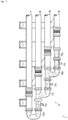
- a coupling mode of exhaust manifolds of an engine 26 including a supercharger 3 according to a first embodiment of the present invention will be specifically described with reference to Figs. 12 and 13 .
- Fig. 12 represents one side parts of exhaust manifolds 27, 28, 29, 30 of the engine 26.
- the engine 26 is a diesel engine, and in the present embodiment, an in-line eight-cylinder engine which has eight cylinders.
- the exhaust manifolds 27, 28, 29, 30 are respectively independently connected to four cylinder groups including cylinders of the same phase of the engine 26 (a group of first and eighth cylinders, a group of second and seventh cylinders, a group of third and sixth cylinders, and a group of fourth and fifth cylinders in the present embodiment).
- the exhaust manifold 27 discharges the exhaust air from the first and eighth cylinders together
- the exhaust manifold 28 discharges the exhaust air from the second and seventh cylinders together
- the exhaust manifold 29 discharges the exhaust air from the third and sixth cylinders together
- the exhaust manifold 30 discharges the exhaust air from the fourth and fifth cylinders together.
- a coupling pipe 31 (hatched part) is detachably coupled to end parts (one side end parts) of the exhaust manifolds 27, 28, 29, 30, the end parts on the opposite side to the supercharger 3.
- the coupling pipe 31 includes a bent pipe 31a, a first on/off valve 31b, a first branch pipe 31c, a second on/off valve 31d, a second branch pipe 31e, a third on/off valve 31f, and an extension pipe 31g.
- the bent pipe 31a, the first on/off valve 31b, the first branch pipe 31c, the second on/off valve 31d, the second branch pipe 31e, the third on/off valve 31f, and the extension pipe 31g are formed in the exhaust manifolds 27, 28, 29, 30 attachably to and detachably from each other. With such a configuration, the coupling pipe 31 is formed so as to couple the three or more independent exhaust manifolds to each other.
- one side end part of the bent pipe 31a is coupled to one side end part of the exhaust manifold 27, and the exhaust manifold 28 is coupled to the other side end part of the bent pipe 31a via the first on/off valve 31b and the first branch pipe 31c.
- the exhaust manifold 29 is coupled to the first branch pipe 31c coupled to the exhaust manifold 28 via the second on/off valve 31d and the second branch pipe 31e.
- the exhaust manifold 30 is coupled to the second branch pipe 31e coupled to the exhaust manifold 29 via the third on/off valve 31f and the extension pipe 31g. That is, the exhaust manifolds 27, 28, 29, 30 are coupled to each other by the coupling pipe 31.
- the one side end parts of the exhaust manifolds 27, 28, 29, 30 are coupled to each other by the coupling pipe 31. That is, the coupling pipe 31 is disposed and concentrated on the one side end parts of the exhaust manifolds 27, 28, 29, 30. Accordingly, in the engine 26, even in a case where the three or more exhaust manifolds 27, 28, 29, 30 are coupled, the exhaust manifolds 27, 28, 29, 30 capable of switching the dynamic pressure supercharging method and the static pressure supercharging method can be formed with a configuration in which attachment and detachment of the coupling pipe 31 and maintenance of the first on/off valve 31b, the second on/off valve 31d, and the third on/off valve 31f are easily performed.
- the engine 1 is a diesel engine, and in the present embodiment, an in-line eight-cylinder engine which has eight cylinders.
- the engine is an in-line eight-cylinder engine including the single stage supercharger 3.
- the present invention is not limited to this but the engine may be a multicylinder engine of eight or more cylinders including a plurality of superchargers 3 (for example, two-stage supercharger).
- an output shaft is driven and rotated by mixing and combusting the outside air and fuel supplied from fuel injection valves 44 inside cylinders 1a.
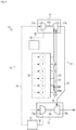
- the engine 1 includes an intake device 2 that takes the outside air in, and an exhaust device 7 that discharges the exhaust air to the outside.
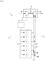
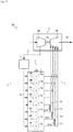
- the engine 1 also includes a rotation speed detection sensor 42, an injection amount detection sensor 43 for the fuel injection valves 44, and an ECU 41 serving as a control device.
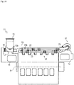
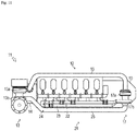
- the exhaust device 7 includes exhaust manifolds 27, 28, 29, 30, and a turbine portion 3b of the supercharger 3.
- the exhaust manifolds 27, 28, 29, 30 are respectively independently connected to four cylinder groups including cylinders of the same phase of the engine 1 (a group of first and eighth cylinders, a group of second and seventh cylinders, a group of third and sixth cylinders, and a group of fourth and fifth cylinders in the present embodiment). That is, the exhaust manifold 27 discharges the exhaust air from the first and eighth cylinders together, the exhaust manifold 28 discharges the exhaust air from the second and seventh cylinders together, the exhaust manifold 29 discharges the exhaust air from the third and sixth cylinders together, and the exhaust manifold 30 discharges the exhaust air from the fourth and fifth cylinders together.
- a coupling pipe 12 (hatched part) is detachably coupled to end parts (one side end parts) of the exhaust manifolds 27, 28, 29, 30.
- the supercharger 3 is connected to the other side end parts of the exhaust manifolds 27, 28, 29, 30.
- the coupling device 12 includes a bent pipe 31a, an on/off valve 31b, a branch pipe 31c, an on/off valve 31d, a branch pipe 31e, an on/off valve 31f, and an extension pipe 31g.
- the bent pipe 31a, the on/off valve 31b, the branch pipe 31c, the on/off valve 31d, the branch pipe 31e, the on/off valve 31f, and the extension pipe 31g are detachable from each other in addition to the exhaust manifolds 27, 28, 29, 30. With such a configuration, the coupling device 12 is formed so as to couple the three or more independent exhaust manifolds to each other.
- one side end part of the bent pipe 31a is coupled to one side end part of the exhaust manifold 27, and the exhaust manifold 28 is coupled to the other side end part of the bent pipe 31a via the on/off valve 31b and the branch pipe 31c.
- the exhaust manifold 29 is coupled to the branch pipe 31c coupled to the exhaust manifold 28 via the on/off valve 31d and the branch pipe 31e.
- the exhaust manifold 30 is coupled to the branch pipe 31e coupled to the exhaust manifold 29 via the on/off valve and the extension pipe 31g. That is, the exhaust manifolds 27, 28, 29, 30 are coupled to each other by the coupling device 12.
- the one side end parts of the exhaust manifolds 27, 28, 29, 30 are coupled to each other by the coupling device 12. That is, the coupling device 12 is disposed and concentrated on the one side end parts of the exhaust manifolds 27, 28, 29, 30.
- the exhaust manifolds 27, 28, 29, 30 capable of switching the dynamic pressure supercharging method and the static pressure supercharging method can be formed with a configuration in which attachment and detachment of the coupling device 12 and maintenance of the on/off valve 31b, the on/off valve 31d, and the on/off valve 31f are easily performed.
- the turbine portion 3b of the supercharger 3 is to generate rotation power by pressure of the exhaust air.
- the turbine portion 3b is coupled to a compressor portion 3a by a coupling shaft 3c, and is configured such that the rotation power can be transmitted to the compressor portion 3a.
- the exhaust manifolds 27, 28, 29, 30 are connected to the turbine portion 3b.
- the turbine portion 3b communicates with the outside via an exhaust pipe 13.
- the compressor portion 3a of the supercharger 3, an air supply pipe 4, an intercooler 5, and an air supply manifold 6 are connected in order from the upstream side (outside).
- the exhaust manifolds 27, 28, 29, 30, the turbine portion 3b of the supercharger 3, and the exhaust pipe 13 are connected in order from the upstream side (engine 1).
- the exhaust manifolds 27, 28, 29, 30 are respectively independently connected to the turbine portion 3b of the supercharger 3. Accordingly, in the exhaust device 7, the exhaust manifolds corresponding to the dynamic pressure supercharging method are formed.
- the exhaust manifold 27 and the exhaust manifold 28 communicate with each other, and the exhaust manifold 29 and the exhaust manifold 30 communicate with each other. That is, the communicating exhaust manifolds 27, 28 and the communicating exhaust manifolds 29, 30 are independently connected to the turbine portion 3b of the supercharger 3. Accordingly, in the exhaust device 7, two sets of exhaust manifolds 27, 28 and exhaust manifolds 29, 30 corresponding to the static pressure supercharging method are formed.
- the exhaust manifold 27, the exhaust manifold 28, and the exhaust manifold 29 communicate with each other. That is, the communicating exhaust manifolds 27, 28, 29 and the exhaust manifold 30 are independently connected to the turbine portion 3b of the supercharger 3. Accordingly, in the exhaust device 7, the exhaust manifolds 27, 28, 29 corresponding to the static pressure supercharging method and the exhaust manifold 30 corresponding to the dynamic pressure supercharging method are mixed and formed.
- the exhaust manifolds 27, 28, 29, 30 are connected to the turbine portion 3b of the supercharger 3 in a state where the exhaust manifolds communicate with each other. That is, in the exhaust device 7, the exhaust manifolds 27, 28, 29, 30 corresponding to the static pressure supercharging method are formed.
- the rotation speed detection sensor 42 is to detect the rotation speed N serving as the engine rotation speed of the engine 1.
- the rotation speed detection sensor 42 is configured by a sensor and a pulsar, and provided in the output shaft of the engine 1.
- the rotation speed detection sensor 42 is configured by the sensor and the pulsar in the present embodiment, the rotation speed detection sensor may be anything capable of detecting the rotation speed N.
- the injection amount detection sensor 43 is to detect an injection amount F of the fuel injected from the fuel injection valves 44.
- the injection amount detection sensor 43 is provided in an intermediate part of a fuel supply pipe (not shown).
- the injection amount detection sensor 43 is configured by a flow rate sensor. Although the injection amount detection sensor 43 is configured by the flow rate sensor in the present embodiment, the present invention is not limited to this and the injection amount detection sensor may be anything capable of detecting the injection amount F of the fuel.
- the ECU 41 is to control the engine 1. Specifically, the ECU controls a main body of the engine 1 and the on/off valves 31b, 31d, 31f. Various programs and data for controlling the engine 1 are stored in the ECU 41.
- the ECU 41 may have a configuration in which a CPU, a ROM, a RAM, a HDD, and the like are connected by a bus, or a configuration in which the ECU includes a single-chip LSI or the like.
- the ECU 41 is connected to the rotation speed detection sensor 42, and is capable of acquiring the rotation speed N detected by the rotation speed detection sensor 42.
- the ECU 41 is connected to the fuel injection valves 44, and is capable of controlling the fuel injection valves 44.
- the ECU 41 is connected to the injection amount detection sensor 43, and is capable of acquiring the injection amount F detected by the injection amount detection sensor 43.
- the ECU 41 is connected to the on/off valves 31b, 31d, 31f of the exhaust manifolds 27, 28, 29, 30, and is capable of controlling an opened/closed state of the on/off valves 31b, 31d, 31f.
- An output torque map M1 for calculating output torque T of the engine 1 based on the acquired rotation speed N and the acquired injection amount F is stored in the ECU 41. Further, a load factor calculation map M2 for calculating a load factor L(n) of the engine 1 based on the acquired rotation speed N and the calculated output torque T is stored in the ECU 41. The load factor L(n) indicates an n-thly calculated load factor L.
- An on/off valve map M3 for determining an opened/closed state of the on/off valves 31b, 31d, 31f to minimize fuel consumption FC of the engine 1 based on the acquired rotation speed N and the calculated load factor L(n) is stored in the ECU 41.
- the on/off valve map M3 stored in the ECU 41 will be described with reference to Figs. 15 and 16 .
- the on/off valve map M3 shows a first reference value La and a second reference value Lb serving as load factors used as a reference for determining an opened/closed state of the on/off valves 31b, 31d, 31f based on the acquired rotation speed N and the calculated load factor L(n) of the engine 1.
- the first reference value La is a load factor in the boundary between a range of the load factor L(n) in which the fuel consumption FC of the engine 1 is minimum when all the on/off valves among the on/off valves 31b, 31d, 31f are in a closed state with an arbitrary rotation speed N of the engine 1, and a range of the load factor L(n) in which the fuel consumption FC is minimum when some of the on/off valves (for example, the on/off valves 31b, 31f) are in an opened state.
- the second reference value Lb is a load factor in the boundary between a range of the load factor L(n) in which the fuel consumption FC of the engine 1 is minimum when some of the on/off valves among the on/off valves 31b, 31d, 31f are in an opened state with an arbitrary rotation speed N of the engine 1, and a range of the load factor L(n) in which the fuel consumption FC is minimum when all the on/off valves are in an opened state. That is, in the engine 1, for each arbitrary rotation speed N, a state of the on/off valves for minimizing the fuel consumption FC is determined from a relationship between the load factor L(n) and the first reference value La and a relationship between the load factor L(n) and the second reference value Lb.
- the on/off valve map M3 is configured by the first reference value La and the second reference value Lb for each number of the rotation speed N of the engine 1. That is, the on/off valve map M3 shows a relationship between a range of the load factor L(n) in which the fuel consumption FC of the engine 1 is minimum for each rotation speed N and a state of the on/off valves 31b, 31d, 31f.
- the ECU 41 calculates the load factor L(n) of the engine 1 from the output torque map M1 and the load factor calculation map M2 based on the acquired rotation speed N and the acquired injection amount F. In a case where an increase/decrease amount of the load factor L(n) per unit time is less than a predetermined value Lc, the ECU 41 judges that an operation state of the engine 1 is fixed. That is, the ECU 41 judges that the vessel 100 is operated in a fixed running mode in which the fuel consumption is focused on. The ECU 41 determines an opened/closed state of the on/off valves 31b, 31d, 31f of the engine 1 from the on/off valve map M3 based on the acquired rotation speed N and the calculated load factor L(n).
- the ECU 41 judges that the operation state of the engine 1 is changing. That is, the ECU 41 judges that the vessel 100 is operated in a transient mode in which a response of acceleration/deceleration is focused on.
- the ECU 41 brings all the on/off valves 31b, 31d, 31f into a closed state irrespective of the acquired rotation speed N and the calculated load factor L(n).
- Step S110 the ECU 41 acquires the rotation speed N detected by the rotation speed detection sensor 42 and the injection amount F detected by the injection amount detection sensor 43, and shifts the flow to Step S120.
- Step S120 the ECU 41 calculates the output torque T of the engine 1 from the output torque map M1 based on the acquired rotation speed N and the acquired injection amount F, and shifts the flow to Step S130.
- Step S130 the ECU 41 calculates the load factor L(n) of the engine 1 from the load factor calculation map M2 based on the acquired rotation speed N and the calculated output torque T, and shifts the flow to Step S140.
- Step S140 the ECU 41 judges whether or not an absolute value of a difference between the calculated L(n) and L(n-1) is less than the predetermined value Lc.
- the ECU 41 shifts the flow to Step S560.
- Step S150 the ECU 41 judges whether or not a state where the absolute value of the difference between the calculated L(n) and L(n-1) is less than the predetermined value Lc is continued for a predetermined period of time T or longer.
- the ECU 41 shifts the flow to Step S200.
- the ECU 41 shifts the flow to Step S560.
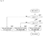
- Step S200 the ECU 41 starts on/off valve control A, and shifts the flow to Step 210 (refer to Fig. 18 ).
- Step S210 the ECU 41 judges whether or not the calculated L(n) is the first reference value La or more.
- Step S220 In a case where the ECU 41 judges that the calculated L(n) is the first reference value La or more as a result, the ECU 41 shifts the flow to Step S220.
- the ECU 41 shifts the flow to Step S430.
- Step S220 the ECU 41 judges whether or not the calculated L(n) is the second reference value Lb or more.
- the ECU 41 shifts the flow to Step S330.
- Step S230 the ECU 41 brings all the on/off valves 31b, 31d, 31f of the exhaust manifolds into an opened state, finishes the on/off valve control A, and shifts the flow to Step S110 (refer to Fig. 17 ).
- Step S330 the ECU 41 brings the on/off valves 31b, 31f or the on/off valves 31b, 31d of the exhaust manifolds into an opened state, finishes the on/off valve control A, and shifts the flow to Step S110 (refer to Fig. 17 ).
- Step S430 the ECU 41 brings all the on/off valves 31b, 31d, 31f of the exhaust manifolds into a closed state, finishes the on/off valve control A, and shifts the flow to Step S110 (refer to Fig. 17 ).
- Step S560 the ECU 41 brings all the on/off valves 31b, 31d, 31f of the exhaust manifolds into a closed state, and shifts the flow to Step S170.
- the engine 1 by switching an opened/closed state of the on/off valves 31b, 31d, 31f of the exhaust manifolds 27, 28, 29, 30 based on the rotation speed N and the load factor L(n), a pressure state of the exhaust air supplied to the supercharger 3 is changed. Accordingly, responsiveness of the supercharger 3 at the time of low-speed rotation of the supercharger 3 and the fuel consumption of the engine 1 at the time of high-speed rotation of the supercharger 3 can be improved.
- a load state of the engine 1 is changed, by switching all the on/off valves 31b, 31d, 31f into a closed state, the responsiveness of the supercharger 3 is improved. Accordingly, generation of black smoke at the time of a transient response can be suppressed and the fuel consumption can also be improved.
- the present invention can be utilized for a technology of an engine with a supercharger.
Landscapes
- Engineering & Computer Science (AREA)
- Chemical & Material Sciences (AREA)
- Combustion & Propulsion (AREA)
- Mechanical Engineering (AREA)
- General Engineering & Computer Science (AREA)
- Supercharger (AREA)
- Exhaust Silencers (AREA)
Claims (2)
- Motor (1), bei dem eine Vielzahl von unabhängigen Abgaskrümmern (27, 28, 29, 30) mit einer Aufladeeinrichtung (3) verbunden ist, wobei die Endteile der Abgaskrümmer (27, 28, 29, 30) durch zwei oder mehr Kupplungsrohre miteinander gekoppelt sind, wobei die Kupplungsrohre ein gebogenes Rohr aufweisen, ein Ein/Aus-Ventil (31b, 31d, 31f), das die Abgaskrümmer (27, 28, 29, 30) in einen unabhängigen Zustand bringt, in jedem der Kupplungsrohre bereitgestellt ist, und in den Kupplungsrohren eine Komponente, die das Ein/Aus-Ventil (31b, 31d, 31f) umfasst, oder das Ein/Aus-Ventil (31b, 31d, 31f) an den Abgaskrümmern (27, 28, 29, 30) angebracht ist, dadurch gekennzeichnet, dass die Kupplungsrohre, die die Abgaskrümmer (27, 28, 29, 30) koppeln, über ein oder mehrere Zweigrohre (31c, 31e) miteinander gekoppelt sind, wobei die Anzahl der Vielzahl von unabhängigen Abgaskrümmern (27, 28, 29, 30) drei oder mehr ist, und dadurch, dass der Motor derart ausgelegt ist, dass ein erster Referenzwert (La) und ein zweiter Referenzwert (Lb) in einem Lastfaktor (L) des Motors (1) je nach Drehgeschwindigkeit des Motors (1) eingestellt werden, und derart, dass in einem Fall, in dem der Lastfaktor (L) geringer ist als der erste Referenzwert (La), alle Ein/Aus-Ventile (31b, 31d, 31f) in einen geschlossenen Zustand gebracht werden, in einem Fall, in dem der Lastfaktor (L) der erste Referenzwert (La) oder mehr und weniger als der zweite Referenzwert (Lb) ist, einige, doch nicht alle Ein/Aus-Ventile (31b, 31d, 31f) in einen offenen Zustand gebracht werden, und in einem Fall, in dem der Lastfaktor (L) der zweite Referenzwert (Lb) oder größer ist, alle Ein/Aus-Ventile (31b, 31d, 31f) in einen offenen Zustand gebracht werden.
- Motor (1) nach Anspruch 1, wobei in einem Fall, in dem ein Zunahme/Abnahmebetrag des Lastfaktors (L) pro Zeiteinheit ein vorbestimmter Wert (Lc) oder größer ist, alle Ein/Aus-Ventile (31b, 31d, 31f) in einen geschlossenen Zustand gebracht werden, und in einem Fall, in dem ein Zunahme/Abnahmebetrag des Lastfaktors (L) pro Zeiteinheit unter den vorbestimmten Wert (Lc) sinkt und für einen vorbestimmten Zeitraum (T) unter diesem gehalten wird, die Ein/Aus-Ventile (31b, 31d, 31f) je nach Lastfaktor (L) geöffnet und geschlossen werden.
Applications Claiming Priority (3)
| Application Number | Priority Date | Filing Date | Title |
|---|---|---|---|
| JP2013222805A JP6073772B2 (ja) | 2013-10-25 | 2013-10-25 | エンジン |
| JP2013222806A JP6148596B2 (ja) | 2013-10-25 | 2013-10-25 | エンジン |
| PCT/JP2014/078019 WO2015060321A1 (ja) | 2013-10-25 | 2014-10-22 | エンジン |
Publications (3)
| Publication Number | Publication Date |
|---|---|
| EP3075979A1 EP3075979A1 (de) | 2016-10-05 |
| EP3075979A4 EP3075979A4 (de) | 2017-05-31 |
| EP3075979B1 true EP3075979B1 (de) | 2019-08-14 |
Family
ID=52992914
Family Applications (1)
| Application Number | Title | Priority Date | Filing Date |
|---|---|---|---|
| EP14856433.9A Not-in-force EP3075979B1 (de) | 2013-10-25 | 2014-10-22 | Motor |
Country Status (5)
| Country | Link |
|---|---|
| US (1) | US9982591B2 (de) |
| EP (1) | EP3075979B1 (de) |
| KR (1) | KR101836019B1 (de) |
| CN (1) | CN105849385B (de) |
| WO (1) | WO2015060321A1 (de) |
Families Citing this family (4)
| Publication number | Priority date | Publication date | Assignee | Title |
|---|---|---|---|---|
| CN108167065A (zh) * | 2017-12-26 | 2018-06-15 | 潍柴动力股份有限公司 | 一种多缸发动机的排气系统 |
| US10690092B2 (en) * | 2018-04-12 | 2020-06-23 | Caterpillar Inc. | EGR system for compound turbocharged engine system |
| US11339715B2 (en) * | 2018-09-28 | 2022-05-24 | Fb Design S.R.L. | Turbocharger assembly |
| EP4731881A1 (de) * | 2023-06-20 | 2026-04-29 | Wärtsilä Finland Oy | Turboladersystem, mehrzylinderkolbenmotor und verfahren zum betreiben eines mehrzylinderkolbenmotors |
Family Cites Families (28)
| Publication number | Priority date | Publication date | Assignee | Title |
|---|---|---|---|---|
| US2660031A (en) * | 1951-01-03 | 1953-11-24 | American Locomotive Co | Exhaust manifold for internalcombustion engines |
| US2773348A (en) * | 1952-03-27 | 1956-12-11 | Nordberg Manufacturing Co | Turbo-charger system, involving plural turbine driven superchargers |
| US2852910A (en) * | 1953-12-29 | 1958-09-23 | Gen Motors Corp | Exhaust manifold |
| US3077071A (en) * | 1960-04-28 | 1963-02-12 | Nordberg Manufacturing Co | Exhaust system for turbocharged engine |
| US3180077A (en) * | 1962-03-20 | 1965-04-27 | Ite Circuit Breaker Ltd | Wave machine to initiate scavenging of internal combustion |
| GB1164018A (en) | 1967-07-11 | 1969-09-10 | Goetaverken Ab | Improvements in or relating to Turbo-Driven Superchargers for Two-Stroke I.C. Engines |
| DE2625788B1 (de) * | 1976-06-09 | 1977-08-11 | Motoren Werke Mannheim Ag | Abgasleitung fuer turboaufgeladene brennkraftmaschinen |
| DE2717684C3 (de) * | 1977-04-21 | 1980-06-26 | Audi Nsu Auto Union Ag, 7107 Neckarsulm | Abgasleitungsanlage für eine mehrzylindrige Brennkraftmaschine mit einem Abgasturbolader |
| JPS60247006A (ja) | 1984-05-22 | 1985-12-06 | Yoichi Yamazaki | 多気筒エンジンの排気装置 |
| DE4342572C1 (de) * | 1993-12-14 | 1994-11-24 | Mtu Friedrichshafen Gmbh | Abgasanlage für eine aufgeladene Brennkraftmaschine |
| JP2001164934A (ja) * | 1999-12-13 | 2001-06-19 | Yanmar Diesel Engine Co Ltd | 内燃機関の排気装置 |
| JP3074863U (ja) | 2000-07-14 | 2001-01-26 | 藤壷技研工業株式会社 | 内燃機関の排気装置 |
| DE10048237A1 (de) * | 2000-09-29 | 2002-04-11 | Daimler Chrysler Ag | Abgasturbolader, aufgeladene Brennkraftmaschine und Verfahren hierzu |
| JP4298972B2 (ja) * | 2002-08-02 | 2009-07-22 | 富士重工業株式会社 | エンジン排気システム及びエンジン排気システムの制御方法 |
| JP4007139B2 (ja) * | 2002-09-30 | 2007-11-14 | マツダ株式会社 | ターボ過給機付エンジンの排気装置 |
| DE102004055571A1 (de) * | 2004-11-18 | 2006-06-08 | Daimlerchrysler Ag | Abgasturbolader für eine Brennkraftmaschine |
| US20060174621A1 (en) * | 2005-02-04 | 2006-08-10 | Kai Chen | Two-turbocharger engine and method |
| DE102005021172A1 (de) | 2005-05-06 | 2006-11-09 | Daimlerchrysler Ag | Brennkraftmaschine mit Abgasturbolader und Abgasrückführung |
| US7788923B2 (en) | 2006-02-02 | 2010-09-07 | International Engine Intellectual Property Company, Llc | Constant EGR rate engine and method |
| DE102006019780A1 (de) * | 2006-04-28 | 2007-11-08 | Daimlerchrysler Ag | Abgasturbolader in einer Brennkraftmaschine |
| DE102006022182A1 (de) * | 2006-05-12 | 2007-11-15 | Daimlerchrysler Ag | Brennkraftmaschine mit einem Abgasturbolader und Abgasrückführung |
| US20080000228A1 (en) * | 2006-06-30 | 2008-01-03 | Caterpillar Inc. | System and method for exhaust recirculation |
| JP4796917B2 (ja) | 2006-08-02 | 2011-10-19 | ヤンマー株式会社 | 過給機付内燃機関の排気制御方法 |
| JP4215085B2 (ja) * | 2006-09-14 | 2009-01-28 | トヨタ自動車株式会社 | 内燃機関 |
| US7891345B2 (en) * | 2008-08-18 | 2011-02-22 | Caterpillar Inc. | EGR system having multiple discharge locations |
| US8201405B2 (en) * | 2008-12-18 | 2012-06-19 | Caterpillar Inc. | Crossover exhaust duct with front inside passage and rear outside passage |
| EP2246543B1 (de) * | 2009-04-01 | 2013-09-04 | Ford Global Technologies, LLC | Zylinderkopf mit zwei Abgaskrümmern und Verfahren zum Betreiben einer Brennkraftmaschine mit einem derartigen Zylinderkopf |
| US8555638B2 (en) * | 2011-04-14 | 2013-10-15 | Caterpillar Inc. | Internal combustion engine with improved exhaust manifold |
-
2014
- 2014-10-22 EP EP14856433.9A patent/EP3075979B1/de not_active Not-in-force
- 2014-10-22 CN CN201480058737.7A patent/CN105849385B/zh not_active Expired - Fee Related
- 2014-10-22 KR KR1020167013718A patent/KR101836019B1/ko not_active Expired - Fee Related
- 2014-10-22 US US15/031,720 patent/US9982591B2/en not_active Expired - Fee Related
- 2014-10-22 WO PCT/JP2014/078019 patent/WO2015060321A1/ja not_active Ceased
Non-Patent Citations (1)
| Title |
|---|
| None * |
Also Published As
| Publication number | Publication date |
|---|---|
| CN105849385A (zh) | 2016-08-10 |
| US9982591B2 (en) | 2018-05-29 |
| US20160265423A1 (en) | 2016-09-15 |
| KR101836019B1 (ko) | 2018-03-07 |
| KR20160081932A (ko) | 2016-07-08 |
| CN105849385B (zh) | 2018-06-26 |
| EP3075979A1 (de) | 2016-10-05 |
| EP3075979A4 (de) | 2017-05-31 |
| WO2015060321A1 (ja) | 2015-04-30 |
Similar Documents
| Publication | Publication Date | Title |
|---|---|---|
| US7788923B2 (en) | Constant EGR rate engine and method | |
| JP4592816B2 (ja) | Scr反応器を備える大型ターボ過給型ディーゼルエンジン | |
| US10513976B2 (en) | Engine system | |
| CN103221661B (zh) | 气缸间空燃比偏差异常检测装置 | |
| US20140190163A1 (en) | Supercharged turbocompound hybrid engine apparatus | |
| EP2683925B1 (de) | Verfahren zur aufrüstung eines motors, aufrüstungskit für einen motor und brennkraftmaschine | |
| CN106468220A (zh) | 带增压器的内燃机的控制装置及其控制方法 | |
| US6381960B1 (en) | Turbocharger housing with exhaust gas recycling | |
| US9982591B2 (en) | Engine | |
| US20180066610A1 (en) | Dedicated egr engine with dedicated loop turbocharger | |
| JP6073772B2 (ja) | エンジン | |
| JP6003239B2 (ja) | 内燃機関 | |
| Liu et al. | Optimizing the exhaust system of marine diesel engines to improve low-speed performances and cylinder working conditions | |
| JP2008280944A (ja) | 過給機付き気体燃料エンジン | |
| JP2013019306A (ja) | ターボチャージャ付き内燃機関の制御装置 | |
| JP6298744B2 (ja) | エンジン | |
| US9719432B2 (en) | Control apparatus for internal combustion engine | |
| EP2527244A1 (de) | System und Verfahren zur Bereitstellung von Wärme auf einem Schiff | |
| JP6148596B2 (ja) | エンジン | |
| US10054039B2 (en) | Turbocharger system for an engine | |
| CN118745953A (zh) | 中冷器系统及其控制方法、控制装置、发动机及车辆 | |
| JP2012132337A (ja) | 過給機付き内燃機関の制御装置 | |
| JPS6019916A (ja) | タ−ボ過給機付エンジン | |
| KR20170119202A (ko) | 엔진 시스템 | |
| JPS5882020A (ja) | 内燃機関用タ−ボス−パ−チヤ−ジヤ |
Legal Events
| Date | Code | Title | Description |
|---|---|---|---|
| PUAI | Public reference made under article 153(3) epc to a published international application that has entered the european phase |
Free format text: ORIGINAL CODE: 0009012 |
|
| 17P | Request for examination filed |
Effective date: 20160525 |
|
| AK | Designated contracting states |
Kind code of ref document: A1 Designated state(s): AL AT BE BG CH CY CZ DE DK EE ES FI FR GB GR HR HU IE IS IT LI LT LU LV MC MK MT NL NO PL PT RO RS SE SI SK SM TR |
|
| AX | Request for extension of the european patent |
Extension state: BA ME |
|
| DAX | Request for extension of the european patent (deleted) | ||
| A4 | Supplementary search report drawn up and despatched |
Effective date: 20170504 |
|
| RIC1 | Information provided on ipc code assigned before grant |
Ipc: F01N 13/10 20100101ALI20170426BHEP Ipc: F02B 37/02 20060101AFI20170426BHEP Ipc: F01N 13/08 20100101ALI20170426BHEP |
|
| STAA | Information on the status of an ep patent application or granted ep patent |
Free format text: STATUS: EXAMINATION IS IN PROGRESS |
|
| 17Q | First examination report despatched |
Effective date: 20180213 |
|
| GRAP | Despatch of communication of intention to grant a patent |
Free format text: ORIGINAL CODE: EPIDOSNIGR1 |
|
| STAA | Information on the status of an ep patent application or granted ep patent |
Free format text: STATUS: GRANT OF PATENT IS INTENDED |
|
| RIC1 | Information provided on ipc code assigned before grant |
Ipc: F01N 13/10 20100101ALI20190208BHEP Ipc: F02B 37/00 20060101ALI20190208BHEP Ipc: F01N 13/08 20100101ALI20190208BHEP Ipc: F02B 37/22 20060101ALI20190208BHEP Ipc: F02B 37/02 20060101AFI20190208BHEP Ipc: F02B 37/013 20060101ALI20190208BHEP |
|
| INTG | Intention to grant announced |
Effective date: 20190304 |
|
| GRAS | Grant fee paid |
Free format text: ORIGINAL CODE: EPIDOSNIGR3 |
|
| GRAA | (expected) grant |
Free format text: ORIGINAL CODE: 0009210 |
|
| STAA | Information on the status of an ep patent application or granted ep patent |
Free format text: STATUS: THE PATENT HAS BEEN GRANTED |
|
| RIN1 | Information on inventor provided before grant (corrected) |
Inventor name: YUKAWA, HIROFUMI Inventor name: TANAKA, HIROKI Inventor name: ONISHI, KENYA Inventor name: NISHIOKA, TAKAAKI |
|
| AK | Designated contracting states |
Kind code of ref document: B1 Designated state(s): AL AT BE BG CH CY CZ DE DK EE ES FI FR GB GR HR HU IE IS IT LI LT LU LV MC MK MT NL NO PL PT RO RS SE SI SK SM TR |
|
| REG | Reference to a national code |
Ref country code: GB Ref legal event code: FG4D |
|
| REG | Reference to a national code |
Ref country code: CH Ref legal event code: EP Ref country code: AT Ref legal event code: REF Ref document number: 1167297 Country of ref document: AT Kind code of ref document: T Effective date: 20190815 |
|
| REG | Reference to a national code |
Ref country code: IE Ref legal event code: FG4D |
|
| REG | Reference to a national code |
Ref country code: DE Ref legal event code: R096 Ref document number: 602014051909 Country of ref document: DE |
|
| REG | Reference to a national code |
Ref country code: NL Ref legal event code: MP Effective date: 20190814 |
|
| REG | Reference to a national code |
Ref country code: LT Ref legal event code: MG4D |
|
| PG25 | Lapsed in a contracting state [announced via postgrant information from national office to epo] |
Ref country code: PT Free format text: LAPSE BECAUSE OF FAILURE TO SUBMIT A TRANSLATION OF THE DESCRIPTION OR TO PAY THE FEE WITHIN THE PRESCRIBED TIME-LIMIT Effective date: 20191216 Ref country code: BG Free format text: LAPSE BECAUSE OF FAILURE TO SUBMIT A TRANSLATION OF THE DESCRIPTION OR TO PAY THE FEE WITHIN THE PRESCRIBED TIME-LIMIT Effective date: 20191114 Ref country code: LT Free format text: LAPSE BECAUSE OF FAILURE TO SUBMIT A TRANSLATION OF THE DESCRIPTION OR TO PAY THE FEE WITHIN THE PRESCRIBED TIME-LIMIT Effective date: 20190814 Ref country code: HR Free format text: LAPSE BECAUSE OF FAILURE TO SUBMIT A TRANSLATION OF THE DESCRIPTION OR TO PAY THE FEE WITHIN THE PRESCRIBED TIME-LIMIT Effective date: 20190814 Ref country code: NL Free format text: LAPSE BECAUSE OF FAILURE TO SUBMIT A TRANSLATION OF THE DESCRIPTION OR TO PAY THE FEE WITHIN THE PRESCRIBED TIME-LIMIT Effective date: 20190814 Ref country code: SE Free format text: LAPSE BECAUSE OF FAILURE TO SUBMIT A TRANSLATION OF THE DESCRIPTION OR TO PAY THE FEE WITHIN THE PRESCRIBED TIME-LIMIT Effective date: 20190814 Ref country code: FI Free format text: LAPSE BECAUSE OF FAILURE TO SUBMIT A TRANSLATION OF THE DESCRIPTION OR TO PAY THE FEE WITHIN THE PRESCRIBED TIME-LIMIT Effective date: 20190814 Ref country code: NO Free format text: LAPSE BECAUSE OF FAILURE TO SUBMIT A TRANSLATION OF THE DESCRIPTION OR TO PAY THE FEE WITHIN THE PRESCRIBED TIME-LIMIT Effective date: 20191114 |
|
| REG | Reference to a national code |
Ref country code: AT Ref legal event code: MK05 Ref document number: 1167297 Country of ref document: AT Kind code of ref document: T Effective date: 20190814 |
|
| PG25 | Lapsed in a contracting state [announced via postgrant information from national office to epo] |
Ref country code: ES Free format text: LAPSE BECAUSE OF FAILURE TO SUBMIT A TRANSLATION OF THE DESCRIPTION OR TO PAY THE FEE WITHIN THE PRESCRIBED TIME-LIMIT Effective date: 20190814 Ref country code: RS Free format text: LAPSE BECAUSE OF FAILURE TO SUBMIT A TRANSLATION OF THE DESCRIPTION OR TO PAY THE FEE WITHIN THE PRESCRIBED TIME-LIMIT Effective date: 20190814 Ref country code: IS Free format text: LAPSE BECAUSE OF FAILURE TO SUBMIT A TRANSLATION OF THE DESCRIPTION OR TO PAY THE FEE WITHIN THE PRESCRIBED TIME-LIMIT Effective date: 20191214 Ref country code: GR Free format text: LAPSE BECAUSE OF FAILURE TO SUBMIT A TRANSLATION OF THE DESCRIPTION OR TO PAY THE FEE WITHIN THE PRESCRIBED TIME-LIMIT Effective date: 20191115 Ref country code: LV Free format text: LAPSE BECAUSE OF FAILURE TO SUBMIT A TRANSLATION OF THE DESCRIPTION OR TO PAY THE FEE WITHIN THE PRESCRIBED TIME-LIMIT Effective date: 20190814 Ref country code: AL Free format text: LAPSE BECAUSE OF FAILURE TO SUBMIT A TRANSLATION OF THE DESCRIPTION OR TO PAY THE FEE WITHIN THE PRESCRIBED TIME-LIMIT Effective date: 20190814 |
|
| PG25 | Lapsed in a contracting state [announced via postgrant information from national office to epo] |
Ref country code: TR Free format text: LAPSE BECAUSE OF FAILURE TO SUBMIT A TRANSLATION OF THE DESCRIPTION OR TO PAY THE FEE WITHIN THE PRESCRIBED TIME-LIMIT Effective date: 20190814 |
|
| PG25 | Lapsed in a contracting state [announced via postgrant information from national office to epo] |
Ref country code: RO Free format text: LAPSE BECAUSE OF FAILURE TO SUBMIT A TRANSLATION OF THE DESCRIPTION OR TO PAY THE FEE WITHIN THE PRESCRIBED TIME-LIMIT Effective date: 20190814 Ref country code: IT Free format text: LAPSE BECAUSE OF FAILURE TO SUBMIT A TRANSLATION OF THE DESCRIPTION OR TO PAY THE FEE WITHIN THE PRESCRIBED TIME-LIMIT Effective date: 20190814 Ref country code: AT Free format text: LAPSE BECAUSE OF FAILURE TO SUBMIT A TRANSLATION OF THE DESCRIPTION OR TO PAY THE FEE WITHIN THE PRESCRIBED TIME-LIMIT Effective date: 20190814 Ref country code: EE Free format text: LAPSE BECAUSE OF FAILURE TO SUBMIT A TRANSLATION OF THE DESCRIPTION OR TO PAY THE FEE WITHIN THE PRESCRIBED TIME-LIMIT Effective date: 20190814 Ref country code: DK Free format text: LAPSE BECAUSE OF FAILURE TO SUBMIT A TRANSLATION OF THE DESCRIPTION OR TO PAY THE FEE WITHIN THE PRESCRIBED TIME-LIMIT Effective date: 20190814 Ref country code: PL Free format text: LAPSE BECAUSE OF FAILURE TO SUBMIT A TRANSLATION OF THE DESCRIPTION OR TO PAY THE FEE WITHIN THE PRESCRIBED TIME-LIMIT Effective date: 20190814 |
|
| PG25 | Lapsed in a contracting state [announced via postgrant information from national office to epo] |
Ref country code: CZ Free format text: LAPSE BECAUSE OF FAILURE TO SUBMIT A TRANSLATION OF THE DESCRIPTION OR TO PAY THE FEE WITHIN THE PRESCRIBED TIME-LIMIT Effective date: 20190814 Ref country code: MC Free format text: LAPSE BECAUSE OF FAILURE TO SUBMIT A TRANSLATION OF THE DESCRIPTION OR TO PAY THE FEE WITHIN THE PRESCRIBED TIME-LIMIT Effective date: 20190814 Ref country code: SK Free format text: LAPSE BECAUSE OF FAILURE TO SUBMIT A TRANSLATION OF THE DESCRIPTION OR TO PAY THE FEE WITHIN THE PRESCRIBED TIME-LIMIT Effective date: 20190814 Ref country code: SM Free format text: LAPSE BECAUSE OF FAILURE TO SUBMIT A TRANSLATION OF THE DESCRIPTION OR TO PAY THE FEE WITHIN THE PRESCRIBED TIME-LIMIT Effective date: 20190814 Ref country code: IS Free format text: LAPSE BECAUSE OF FAILURE TO SUBMIT A TRANSLATION OF THE DESCRIPTION OR TO PAY THE FEE WITHIN THE PRESCRIBED TIME-LIMIT Effective date: 20200224 |
|
| REG | Reference to a national code |
Ref country code: CH Ref legal event code: PL |
|
| REG | Reference to a national code |
Ref country code: DE Ref legal event code: R097 Ref document number: 602014051909 Country of ref document: DE |
|
| PLBE | No opposition filed within time limit |
Free format text: ORIGINAL CODE: 0009261 |
|
| STAA | Information on the status of an ep patent application or granted ep patent |
Free format text: STATUS: NO OPPOSITION FILED WITHIN TIME LIMIT |
|
| PG2D | Information on lapse in contracting state deleted |
Ref country code: IS |
|
| PG25 | Lapsed in a contracting state [announced via postgrant information from national office to epo] |
Ref country code: CH Free format text: LAPSE BECAUSE OF NON-PAYMENT OF DUE FEES Effective date: 20191031 Ref country code: LU Free format text: LAPSE BECAUSE OF NON-PAYMENT OF DUE FEES Effective date: 20191022 Ref country code: LI Free format text: LAPSE BECAUSE OF NON-PAYMENT OF DUE FEES Effective date: 20191031 |
|
| 26N | No opposition filed |
Effective date: 20200603 |
|
| REG | Reference to a national code |
Ref country code: BE Ref legal event code: MM Effective date: 20191031 |
|
| PG25 | Lapsed in a contracting state [announced via postgrant information from national office to epo] |
Ref country code: SI Free format text: LAPSE BECAUSE OF FAILURE TO SUBMIT A TRANSLATION OF THE DESCRIPTION OR TO PAY THE FEE WITHIN THE PRESCRIBED TIME-LIMIT Effective date: 20190814 Ref country code: BE Free format text: LAPSE BECAUSE OF NON-PAYMENT OF DUE FEES Effective date: 20191031 |
|
| GBPC | Gb: european patent ceased through non-payment of renewal fee |
Effective date: 20191114 |
|
| REG | Reference to a national code |
Ref country code: DE Ref legal event code: R082 Ref document number: 602014051909 Country of ref document: DE Representative=s name: JOSTARNDT PATENTANWALTS-AG, DE Ref country code: DE Ref legal event code: R081 Ref document number: 602014051909 Country of ref document: DE Owner name: YANMAR POWER TECHNOLOGY CO., LTD., JP Free format text: FORMER OWNER: YANMAR CO., LTD., OSAKA-SHI, JP |
|
| PG25 | Lapsed in a contracting state [announced via postgrant information from national office to epo] |
Ref country code: IE Free format text: LAPSE BECAUSE OF NON-PAYMENT OF DUE FEES Effective date: 20191022 Ref country code: FR Free format text: LAPSE BECAUSE OF NON-PAYMENT OF DUE FEES Effective date: 20191031 Ref country code: GB Free format text: LAPSE BECAUSE OF NON-PAYMENT OF DUE FEES Effective date: 20191114 |
|
| PG25 | Lapsed in a contracting state [announced via postgrant information from national office to epo] |
Ref country code: CY Free format text: LAPSE BECAUSE OF FAILURE TO SUBMIT A TRANSLATION OF THE DESCRIPTION OR TO PAY THE FEE WITHIN THE PRESCRIBED TIME-LIMIT Effective date: 20190814 |
|
| PG25 | Lapsed in a contracting state [announced via postgrant information from national office to epo] |
Ref country code: MT Free format text: LAPSE BECAUSE OF FAILURE TO SUBMIT A TRANSLATION OF THE DESCRIPTION OR TO PAY THE FEE WITHIN THE PRESCRIBED TIME-LIMIT Effective date: 20190814 Ref country code: HU Free format text: LAPSE BECAUSE OF FAILURE TO SUBMIT A TRANSLATION OF THE DESCRIPTION OR TO PAY THE FEE WITHIN THE PRESCRIBED TIME-LIMIT; INVALID AB INITIO Effective date: 20141022 |
|
| PGFP | Annual fee paid to national office [announced via postgrant information from national office to epo] |
Ref country code: DE Payment date: 20211020 Year of fee payment: 8 |
|
| PG25 | Lapsed in a contracting state [announced via postgrant information from national office to epo] |
Ref country code: MK Free format text: LAPSE BECAUSE OF FAILURE TO SUBMIT A TRANSLATION OF THE DESCRIPTION OR TO PAY THE FEE WITHIN THE PRESCRIBED TIME-LIMIT Effective date: 20190814 |
|
| REG | Reference to a national code |
Ref country code: DE Ref legal event code: R119 Ref document number: 602014051909 Country of ref document: DE |
|
| PG25 | Lapsed in a contracting state [announced via postgrant information from national office to epo] |
Ref country code: DE Free format text: LAPSE BECAUSE OF NON-PAYMENT OF DUE FEES Effective date: 20230503 |