EP3076014A1 - Système d'évaluation de fatigue, générateur de turbine éolienne comportant celui-ci et procédé d'évaluation de fatigue pour générateur de turbine éolienne - Google Patents
Système d'évaluation de fatigue, générateur de turbine éolienne comportant celui-ci et procédé d'évaluation de fatigue pour générateur de turbine éolienne Download PDFInfo
- Publication number
- EP3076014A1 EP3076014A1 EP15180809.4A EP15180809A EP3076014A1 EP 3076014 A1 EP3076014 A1 EP 3076014A1 EP 15180809 A EP15180809 A EP 15180809A EP 3076014 A1 EP3076014 A1 EP 3076014A1
- Authority
- EP
- European Patent Office
- Prior art keywords
- fatigue
- dynamic pressure
- wind turbine
- turbine generator
- basis
- Prior art date
- Legal status (The legal status is an assumption and is not a legal conclusion. Google has not performed a legal analysis and makes no representation as to the accuracy of the status listed.)
- Withdrawn
Links
Images



Classifications
-
- F—MECHANICAL ENGINEERING; LIGHTING; HEATING; WEAPONS; BLASTING
- F03—MACHINES OR ENGINES FOR LIQUIDS; WIND, SPRING, OR WEIGHT MOTORS; PRODUCING MECHANICAL POWER OR A REACTIVE PROPULSIVE THRUST, NOT OTHERWISE PROVIDED FOR
- F03D—WIND MOTORS
- F03D17/00—Monitoring or testing of wind motors, e.g. diagnostics
-
- F—MECHANICAL ENGINEERING; LIGHTING; HEATING; WEAPONS; BLASTING
- F05—INDEXING SCHEMES RELATING TO ENGINES OR PUMPS IN VARIOUS SUBCLASSES OF CLASSES F01-F04
- F05B—INDEXING SCHEME RELATING TO WIND, SPRING, WEIGHT, INERTIA OR LIKE MOTORS, TO MACHINES OR ENGINES FOR LIQUIDS COVERED BY SUBCLASSES F03B, F03D AND F03G
- F05B2270/00—Control
- F05B2270/30—Control parameters, e.g. input parameters
- F05B2270/32—Wind speeds
-
- F—MECHANICAL ENGINEERING; LIGHTING; HEATING; WEAPONS; BLASTING
- F05—INDEXING SCHEMES RELATING TO ENGINES OR PUMPS IN VARIOUS SUBCLASSES OF CLASSES F01-F04
- F05B—INDEXING SCHEME RELATING TO WIND, SPRING, WEIGHT, INERTIA OR LIKE MOTORS, TO MACHINES OR ENGINES FOR LIQUIDS COVERED BY SUBCLASSES F03B, F03D AND F03G
- F05B2270/00—Control
- F05B2270/30—Control parameters, e.g. input parameters
- F05B2270/332—Maximum loads or fatigue criteria
-
- Y—GENERAL TAGGING OF NEW TECHNOLOGICAL DEVELOPMENTS; GENERAL TAGGING OF CROSS-SECTIONAL TECHNOLOGIES SPANNING OVER SEVERAL SECTIONS OF THE IPC; TECHNICAL SUBJECTS COVERED BY FORMER USPC CROSS-REFERENCE ART COLLECTIONS [XRACs] AND DIGESTS
- Y02—TECHNOLOGIES OR APPLICATIONS FOR MITIGATION OR ADAPTATION AGAINST CLIMATE CHANGE
- Y02E—REDUCTION OF GREENHOUSE GAS [GHG] EMISSIONS, RELATED TO ENERGY GENERATION, TRANSMISSION OR DISTRIBUTION
- Y02E10/00—Energy generation through renewable energy sources
- Y02E10/70—Wind energy
- Y02E10/72—Wind turbines with rotation axis in wind direction
Definitions
- the present disclosure relates to a fatigue evaluation system, a wind turbine generator having the same, and a fatigue evaluation method for a wind turbine generator.
- a wind turbine power generation facility generates electric power by utilizing wind as renewable energy.
- a wind turbine power generating facility includes a rotor including a plurality of rotor blades for receiving wind energy and a rotor hub, a generator to which a rotational force of the rotor is transmitted via a drivetrain, a nacelle which supports the rotor rotatably and houses the generator, and a tower which supports the nacelle.
- Patent Document 1 discloses a monitoring system for a wind turbine power generation facility configured to evaluate fatigue of components such as rotor blades and a drivetrain of a wind turbine power generation facility using a Rainflow process.
- Patent Document 1 EP1760311A
- the monitoring system described in Patent Document 1 requires time-series data of a load at a target section of a wind turbine generator that is to be evaluated. It is difficult to store the time-series data of a load for a long period of time given the amount of the data. Further, in the monitoring system described in Patent Document 1, there is a high load due to the calculation process for calculating load amplitude and occurrence frequency from the time-series data of a load. Thus, a long processing time is required to evaluate fatigue.
- An object of at least some embodiments of the present invention is to provide an evaluation system for a wind turbine generator capable of performing simplified fatigue evaluation which does not require acquisition of time-series data of a load, and of reducing the time for the fatigue evaluation, as well as a wind turbine generator having the same and a fatigue evaluation method for a wind turbine generator.
- a fatigue evaluation system for a wind turbine generator includes: an anemometer for measuring wind velocity of wind; a statistical processing part for calculating a mean value U and a standard deviation ⁇ of the wind velocity on the basis of a measurement result of the anemometer; a frequency-distribution calculation part configured to calculate occurrence frequency distribution of a fluctuating dynamic pressure of the wind, on the basis of a product of the mean value U and the standard deviation ⁇ calculated by the statistical processing part; and a fatigue estimation part for estimating fatigue of the wind turbine generator, on the basis of the occurrence-frequency distribution of the fluctuating dynamic pressure.
- a wind load applied to a rotor is transmitted to a nacelle base plate via main bearings supporting the rotor, and then to a tower via the nacelle base plate.
- fluctuating stress is generated at many sections (e.g. a blade root of each blade, an upper end part of the tower or a base part of the tower) disposed in such a transmission path of a load.
- the fluctuating stress shows a strong correlation to a fluctuation component of a load due to wind acting on the rotor.
- fatigue of a material depends on occurrence frequency of stress amplitude of fluctuating stress generated in the material.
- the above configuration (1) is based on the above findings of the present inventors, and capable of performing fatigue evaluation on the basis of occurrence frequency distribution of a fluctuating dynamic pressure calculated on the basis of a product of statistics of wind velocity (the mean value U and the standard deviation ⁇ ), even if time-series data of a load is not available. Further, it is possible to reduce the operation time required to evaluate fatigue as compared to a case where fatigue is evaluated on the basis of occurrence frequency of load amplitude calculated by a known method (e.g. Rainflow method) from time-series data of a load.
- a known method e.g. Rainflow method
- the thrust coefficient C T may vary in accordance with a control of the pitch angles of the blades. For instance, in a typical variable-pitch wind turbine, the pitch angle of the blades is controlled to maintain the power output at the rated output or less, and the thrust coefficient C T decreases in a region with high wind velocity of not less than the rated wind velocity as compared to in a region with the rated wind velocity.
- the moment coefficient C M may vary in accordance with a control of the pitch angles of the blades. For instance, in a typical variable-pitch wind turbine, the pitch angle of the blades is controlled to maintain the power output at the rated output or less, and the moment coefficient C M decreases in a region with high wind velocity of not less than the rated wind velocity as compared to in a region with the rated wind velocity.
- the fatigue estimation part is configured to estimate the fatigue on the basis of the occurrence frequency n i of the fluctuating dynamic pressure P i .
- X 3 ⁇ ⁇ U ⁇ ⁇
- the fatigue estimation part is configured to estimate the fatigue on the basis of a comparison result between: reference occurrence-frequency distribution of the fluctuating dynamic pressure corresponding to a known fatigue lifetime related to the wind turbine generator, and the occurrence frequency distribution of the fluctuating dynamic pressure calculated by the frequency-distribution calculation part.
- the fatigue estimation part is configured to estimate the fatigue on the basis of a ratio n i /N i of the occurrence frequency n i of the fluctuating dynamic pressure P i to occurrence frequency N i of the fluctuating dynamic pressure P i in the reference occurrence-frequency distribution.
- i is a range number of the fluctuating dynamic pressure in the occurrence-frequency distribution or the reference occurrence-frequency distribution.
- the known fatigue lifetime is a design lifetime of the wind turbine generator
- the reference occurrence frequency distribution is occurrence frequency distribution of the fluctuating dynamic pressure taken into account in designing the wind turbine generator.
- a wind turbine generator includes: a rotor configured to rotate by receiving wind; a generator to which a rotational force of the rotor is transmitted, the generator being configured to be driven by the rotational force; and the fatigue evaluation system according to any one of the above (1) to (9).
- a method of evaluating fatigue of a wind turbine generator includes: a wind-velocity measurement step of measuring wind velocity of wind; a statistical processing step of calculating a mean value U and a standard deviation ⁇ of the wind velocity on the basis of a measurement result of the wind velocity; a frequency-distribution calculation step of calculating occurrence-frequency distribution of a fluctuating dynamic pressure of the wind, on the basis of a product of the mean value U and the standard deviation ⁇ calculated in the statistical processing step; and a fatigue estimation step of estimating fatigue of the wind turbine generator, on the basis of the occurrence frequency distribution of the fluctuating dynamic pressure.
- the fatigue estimation step includes estimating the fatigue on the basis of a comparison result between: reference occurrence-frequency distribution of the fluctuating dynamic pressure corresponding to a known fatigue lifetime related to the wind turbine generator; and the occurrence frequency distribution of the fluctuating dynamic pressure calculated in the frequency-distribution calculation step.
- the fatigue estimation step includes estimating the fatigue on the basis of a ratio n i /N i of the occurrence frequency n i of the fluctuating dynamic pressure P i to occurrence frequency N i of the fluctuating dynamic pressure P i in the reference occurrence-frequency distribution.
- the fatigue estimation step includes calculating a fatigue damage level D on the basis of a following equation (1), and estimating the fatigue on the basis of the fatigue damage level D.
- D ⁇ n i N i
- i is a range number of the fluctuating dynamic pressure in the occurrence-frequency distribution or the reference occurrence-frequency distribution.
- the known fatigue lifetime is a design lifetime of the wind turbine generator
- the reference occurrence frequency distribution is occurrence frequency distribution of the fluctuating dynamic pressure taken into account in designing the wind turbine generator.
- FIG. 1 is an overall configuration diagram of a wind turbine generator 1 according to one embodiment.
- a wind turbine generator 1 includes at least one blade 2, a rotation shaft 4 configured to rotate along with the blade 2, and a generator 6 configured to be driven by rotation energy of a rotor 5 including the blade 2 and the rotation shaft 4.
- the wind turbine generator 1 may be placed on land or on ocean.
- a plurality of blades 2 is mounted around a hub 3.
- the hub 3 is mounted to an end portion of the rotation shaft 4, and the rotor 5 includes the blades 2, the hub 3, and the rotation shaft 4.
- the rotation shaft 4 is supported rotatably to a nacelle base plate 7a of a nacelle 7 via main bearings 8.
- the nacelle base plate 7a is mounted to an end portion of a tower 9.
- a drivetrain such as a gear and a hydraulic transmission may be disposed between the rotation shaft 4 and the generator 6.
- a hydraulic transmission includes a hydraulic pump mounted to the rotation shaft 4 and a hydraulic motor connected to the hydraulic pump via a high-pressure oil line and a low-pressure oil line.
- the pressurized oil generated by the hydraulic pump is supplied to the hydraulic motor via the high-pressure oil line, and the hydraulic motor is driven by this pressurized oil.
- the low-pressure working oil having performed work in the hydraulic motor is returned again to the hydraulic pump via the low-pressure oil line.
- the output shaft of the hydraulic motor is connected to the input shaft of the generator 6, so that rotation of the hydraulic motor is inputted into the generator 6 and electric power is generated.
- the above wind turbine generator 1 further includes a fatigue-evaluation system 10 capable of performing simplified fatigue evaluation which does not require acquisition of time-series data of a load.
- the fatigue-evaluation system 10 is to evaluate fatigue of each section of the wind turbine generator 1.
- a section to be subject to the fatigue evaluation is, for example, a blade root of each blade 2, a tip end part of the tower 9, a base part of the tower 9, or the like.
- the fatigue-evaluation system 10 includes an anemometer 11 for measuring wind velocity and an arithmetic processing part 12 for evaluating fatigue of the wind turbine generator 1 on the basis of the measurement result of the anemometer 11.
- the arithmetic processing part 12 may be disposed on a control device inside the nacelle 7 or the tower 9 of the wind turbine generator 1, or on a supervisory control and data acquisition device (SCADA) installed at a remote place.
- SCADA supervisory control and data acquisition device
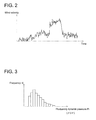
- the anemometer 11 is disposed on the wind turbine generator 1 or in the vicinity of the same. In the illustrated example, the anemometer 11 is disposed on an upper part of the nacelle 7 of the wind turbine generator 1. For instance, the anemometer 11 measures wind velocity continuously, and obtains time-series data of wind velocity as illustrated in FIG. 2 .
- the arithmetic processing part 12 includes a statistical processing part 13, a frequency-distribution calculation part 14, and a fatigue estimation part 15.
- the statistical processing part 13 is configured to calculate a mean value U of wind velocity (wind-velocity mean) and a standard deviation ⁇ on the basis of the measurement result of the anemometer 11 as illustrated in FIG. 2 .
- the mean value U and the standard deviation ⁇ of wind velocity are calculated every predetermined period (e.g. 10 minutes) by a statistical method.
- the frequency-distribution calculation part 14 is configured to calculate occurrence frequency distribution of a fluctuating dynamic pressure P i of wind, on the basis of a product of the mean value U and the standard deviation ⁇ calculated by the statistical processing part 13.
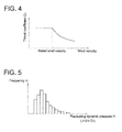
- the fatigue-estimation part 15 is configured to estimate fatigue of a wind turbine generator on the basis of occurrence frequency distribution of a fluctuating dynamic pressure calculated by the frequency-distribution calculation part 14. Specifically, the fatigue estimation part 15 is configured to estimate fatigue on the basis of occurrence frequency n i of a fluctuating dynamic pressure P i as illustrated in FIG. 3 . The fatigue estimation by the fatigue estimation part 15 will be described later.
- a wind load applied to the rotor 5 is transmitted to the nacelle base plate 7a via the main bearings 8 supporting the rotor 5, and also to the tower 9 via the nacelle base plate 7a.
- fluctuating stress is generated at many sections (e.g. a blade root of each blade 2, an upper end part of the tower 9 or a base part of the tower 9) disposed in such a transmission path of a load.
- the fluctuating stress shows a strong correlation to a fluctuation component of a load due to wind acting on the rotor 5.
- the fatigue of a material depends on occurrence frequency of stress amplitude of fluctuating stress generated in the material.
- the above configuration is based on the above findings of the present inventors, and capable of performing fatigue evaluation on the basis of the occurrence frequency distribution of a fluctuating dynamic pressure calculated on the basis of a product of statistics regarding wind velocity (the mean value U and the standard deviation ⁇ ), even when time-series data of a load is not available. Further, it is possible to reduce the operation time required to evaluate fatigue as compared to a case where fatigue is evaluated on the basis of the occurrence frequency of load amplitude calculated by a known method (e.g. Rainflow method) from time-series data of a load.
- a known method e.g. Rainflow method
- the fatigue estimation part 15 is configured to estimate fatigue on the basis of the occurrence frequency n i of the fluctuating dynamic pressure P i .
- the thrust coefficient C T is taken into account as a factor that affects a load M applied to the rotor 5, and fatigue is estimated with higher accuracy.
- the load M (thrust load) due to wind acting on the rotor 5 is calculated from the following equation (2).
- M 1 / 2 ⁇ U 2 C T A
- M is a load (thrust load)
- ⁇ is an air density
- U is a mean value of wind velocity
- C T is a thrust coefficient
- A is a rotor area.
- the thrust coefficient C T may vary in accordance with a control of the pitch angle of the blades 2.
- the pitch angle of the blades 2 is controlled to maintain the power output at the rated output or less, and the thrust coefficient C T decreases in a region with high wind velocity of not less than the rated wind velocity as compared to in a region with the rated wind velocity.
- FIG. 4 is a graph of a relationship between wind velocity and a thrust coefficient.
- FIG. 5 is a graph of an example of frequency distribution of a fluctuating dynamic pressure P i ( ⁇ U ⁇ C T ).
- the fatigue estimation part 15 is configured to estimate fatigue on the basis of the occurrence frequency n i of the fluctuating dynamic pressure P i .
- the moment coefficient C M is taken into account as a factor that affects a load M applied to the rotor 5, and fatigue is estimated with higher accuracy.
- the load M (moment load) due to wind acting on the rotor 5 is calculated from the following equation (3).
- M 1 / 2 ⁇ U 2 C M A
- M is a load (moment load)
- ⁇ is an air density
- U is a mean value of wind velocity
- C M is a moment coefficient
- A is a rotor area.
- the moment coefficient C M may vary in accordance with a control of the pitch angles of the blades 2.
- the pitch angle of the blades 2 is controlled to maintain the power output at the rated output or less, and the moment coefficient C M decreases in a region with high wind velocity of not less than the rated wind velocity as compared to in a region with the rated wind velocity.
- FIG. 6 is a graph of a relationship between wind velocity and a moment coefficient.
- FIG. 7 is a graph of an example of frequency distribution of the fluctuating dynamic pressure P i ( ⁇ U ⁇ C M ).
- the fatigue estimation part 15 is configured to estimate fatigue on the basis of a comparison result between: reference occurrence-frequency distribution of a fluctuating dynamic pressure P i corresponding to a known fatigue lifetime related to the wind turbine generator 1; and occurrence frequency distribution of a fluctuating dynamic pressure P i calculated by the frequency-distribution calculation part.
- the fatigue estimation part 15 is configured to estimate fatigue on the basis of a ratio n i /N i of occurrence frequency n i of a fluctuating dynamic pressure P i to occurrence frequency N i of a fluctuating dynamic pressure P i in the reference occurrence-frequency distribution.
- the fatigue estimation part 15 is configured to calculate a fatigue damage level D on the basis of the following equation (1), and to estimate fatigue on the basis of the fatigue damage level D.
- D ⁇ n i N i
- i is a range number of a fluctuating dynamic pressure in the occurrence-frequency distribution or the reference occurrence-frequency distribution.
- the known fatigue lifetime is the design lifetime of the wind turbine generator 1
- the reference occurrence-frequency distribution is occurrence-frequency distribution of a fluctuating dynamic pressure taken into account in designing the wind turbine generator 1.
- FIG. 8 is a graph of an example of wind-velocity frequency distribution taken into account in designing.
- FIG. 9 is a graph of an example of wind-velocity standard deviation distribution taken into account in designing.
- FIG. 10 is a graph of frequency distribution (reference occurrence-frequency distribution) of a fluctuating dynamic pressure taken into account in designing.
- the frequency distribution (reference occurrence frequency distribution) of a fluctuating dynamic pressure taken into account in designing the wind turbine generator 1 is calculated from the wind-velocity frequency distribution taken into account in designing illustrated in FIG. 8 and the wind-velocity standard deviation distribution taken into account in designing illustrated in FIG. 9 .
- the frequency distribution of a fluctuating dynamic pressure taken into account in designing the wind turbine generator 1 is calculated from a product of the wind-velocity frequency distribution taken into account in designing, the wind-velocity standard deviation distribution taken into account in designing, and the thrust coefficient C T or the moment coefficient C M of the wind turbine generator 1.
- the wind-velocity frequency distribution taken into account in designing is obtained by, for instance, estimating a wind-velocity appearance ratio in each range from yearly average wind velocity U ave , assuming Rayleigh distribution.
- the yearly average wind velocity U ave is determined by a design class of the wind turbine generator 1 being subject to evaluation.
- the wind-velocity standard deviation distribution taken into account in designing is obtained from a standard turbulence model of the IEC standard, for instance. At this time, turbulence determined by the design class of the wind turbine generator 1 being subject to evaluation is used as reference turbulence.
- the frequency distribution of a fluctuating dynamic pressure (reference occurrence frequency distribution) at the time when the wind turbine generator 1 to be evaluated reaches the design lifetime is calculated.
- the fatigue estimation part 15 calculates the fatigue damage level D of a target section of the wind turbine generator 1 from the above equation (1) by comparing the occurrence frequency distribution (see FIG. 3 ) of the fluctuating dynamic pressure P i up until a current time in actual operation of the wind turbine generator 1 calculated by the statistical processing part 13 and the frequency-distribution calculation part 14 to the frequency distribution (see FIG. 10 ) of a fluctuating dynamic pressure at the time when the wind turbine generator 1 reaches the design lifetime.
- FIG. 11 is a flowchart of a fatigue evaluation method of the wind turbine generator 1.
- reference numerals illustrated in FIG. 1 are used where appropriate.
- the wind velocity is measured by the anemometer 11 in the wind-velocity measurement step S1.
- the mean value U and the standard deviation ⁇ of wind velocity are calculated on the basis of the measurement results of wind velocity.
- the occurrence frequency distribution of a fluctuating dynamic pressure of wind is calculated on the basis of a product of the mean value U and the standard deviation ⁇ calculated in the statistical processing step S2.
- X 2 U ⁇ ⁇ ⁇ C T
- fatigue of the wind turbine generator is estimated on the basis of the occurrence frequency distribution of a fluctuating dynamic pressure.
- the fatigue is estimated on the basis of a comparison result between: reference occurrence-frequency distribution of a fluctuating dynamic pressure P i corresponding to a known fatigue lifetime related to the wind turbine generator 1; and occurrence frequency distribution of a fluctuating dynamic pressure calculated in the frequency distribution calculation step.
- fatigue is estimated on the basis of a ratio n i /N i of occurrence frequency n i of a fluctuating dynamic pressure P i to occurrence frequency N i of a fluctuating dynamic pressure P i in the reference occurrence-frequency distribution.
- the fatigue damage level D may be calculated on the basis of the following equation (1), and the fatigue may be estimated on the basis of the fatigue damage level D.
- D ⁇ n i N i
- i is a range number of a fluctuating dynamic pressure in the occurrence-frequency distribution or the reference occurrence-frequency distribution.
- the known fatigue lifetime may be the design lifetime of the wind turbine generator 1
- the reference occurrence-frequency distribution may be occurrence-frequency distribution of a fluctuating dynamic pressure taken into account in designing the wind turbine generator.
- an expression of relative or absolute arrangement such as “in a direction”, “along a direction”, “parallel”, “orthogonal”, “centered”, “concentric” and “coaxial” shall not be construed as indicating only the arrangement in a strict literal sense, but also includes a state where the arrangement is relatively displaced by a tolerance, or by an angle or a distance whereby it is possible to achieve the same function.
- an expression of an equal state such as “same” “equal” and “uniform” shall not be construed as indicating only the state in which the feature is strictly equal, but also includes a state in which there is a tolerance or a difference that can still achieve the same function.
- an expression of a shape such as a rectangular shape or a cylindrical shape shall not be construed as only the geometrically strict shape, but also includes a shape with unevenness or chamfered corners within the range in which the same effect can be achieved.
Landscapes
- Engineering & Computer Science (AREA)
- Life Sciences & Earth Sciences (AREA)
- Sustainable Development (AREA)
- Sustainable Energy (AREA)
- Chemical & Material Sciences (AREA)
- Combustion & Propulsion (AREA)
- Mechanical Engineering (AREA)
- General Engineering & Computer Science (AREA)
- Wind Motors (AREA)
Applications Claiming Priority (1)
| Application Number | Priority Date | Filing Date | Title |
|---|---|---|---|
| JP2015069217A JP6309911B2 (ja) | 2015-03-30 | 2015-03-30 | 疲労評価システム及びこれを備えた風力発電装置、並びに、風力発電装置の疲労評価方法 |
Publications (1)
| Publication Number | Publication Date |
|---|---|
| EP3076014A1 true EP3076014A1 (fr) | 2016-10-05 |
Family
ID=53879375
Family Applications (1)
| Application Number | Title | Priority Date | Filing Date |
|---|---|---|---|
| EP15180809.4A Withdrawn EP3076014A1 (fr) | 2015-03-30 | 2015-08-12 | Système d'évaluation de fatigue, générateur de turbine éolienne comportant celui-ci et procédé d'évaluation de fatigue pour générateur de turbine éolienne |
Country Status (2)
| Country | Link |
|---|---|
| EP (1) | EP3076014A1 (fr) |
| JP (1) | JP6309911B2 (fr) |
Cited By (5)
| Publication number | Priority date | Publication date | Assignee | Title |
|---|---|---|---|---|
| CN107832881A (zh) * | 2017-11-02 | 2018-03-23 | 南方电网科学研究院有限责任公司 | 考虑负荷水平和风速分段的风电功率预测误差评价方法 |
| CN110262454A (zh) * | 2019-06-25 | 2019-09-20 | 三一重能有限公司 | 风机控制系统的测试系统、方法及装置 |
| US11105315B2 (en) | 2017-07-18 | 2021-08-31 | Beijing Goldwind Science & Creation Windpower Equipment Co., Ltd. | Method and device for controlling output power of a wind turbine |
| CN114971305A (zh) * | 2022-05-30 | 2022-08-30 | 中车株洲电力机车研究所有限公司 | 一种基于bladed疲劳载荷的分扇区校核方法及系统 |
| CN119957437A (zh) * | 2025-01-07 | 2025-05-09 | 国电甘肃新能源有限公司 | 一种基于数据分析的风机设备故障预警方法及系统 |
Families Citing this family (5)
| Publication number | Priority date | Publication date | Assignee | Title |
|---|---|---|---|---|
| JP6315836B2 (ja) * | 2016-07-04 | 2018-04-25 | 株式会社日本製鋼所 | 風車の監視装置、風車の監視方法および風車の監視プログラム |
| JP6906354B2 (ja) * | 2017-04-24 | 2021-07-21 | 株式会社東芝 | 風車発電機の疲労損傷量算出装置、風力発電システム、及び風車発電機の疲労損傷量算出方法 |
| JP6865672B2 (ja) * | 2017-12-04 | 2021-04-28 | 株式会社日立製作所 | 風力発電装置の評価方法および設計方法 |
| KR102406870B1 (ko) * | 2020-04-10 | 2022-06-10 | 군산대학교산학협력단 | 유효 전력 조절 하에서의 풍력 터빈 피로 하중 모델 구축 방법 |
| JP7684107B2 (ja) * | 2021-06-22 | 2025-05-27 | 株式会社日立製作所 | 風力発電装置の余寿命診断方法および余寿命診断装置 |
Citations (4)
| Publication number | Priority date | Publication date | Assignee | Title |
|---|---|---|---|---|
| EP1760311A2 (fr) | 2005-09-02 | 2007-03-07 | General Electric Company | Méthode et dispositif de suivi des parts d'une éolienne basés sur les conditions en fonctionnement |
| US20100138267A1 (en) * | 2009-08-31 | 2010-06-03 | Sameer Vittal | System and method for wind turbine health management |
| EP2264314A2 (fr) * | 2009-05-25 | 2010-12-22 | Vestas Wind Systems A/S | Procédé et système pour contrôler le fonctionnement d'une éolienne |
| US20140288855A1 (en) * | 2013-03-20 | 2014-09-25 | United Technologies Corporation | Temporary Uprating of Wind Turbines to Maximize Power Output |
Family Cites Families (4)
| Publication number | Priority date | Publication date | Assignee | Title |
|---|---|---|---|---|
| JP3962645B2 (ja) * | 2002-07-25 | 2007-08-22 | 三菱重工業株式会社 | 風車の運転制御装置 |
| JP2004101417A (ja) * | 2002-09-11 | 2004-04-02 | Mitsubishi Heavy Ind Ltd | 監視装置 |
| JP2005240785A (ja) * | 2004-02-27 | 2005-09-08 | Mitsubishi Heavy Ind Ltd | 浮体式風力発電装置の設計方法及び浮体式風力発電装置の設計用プログラム |
| DK1988284T5 (da) * | 2007-05-03 | 2019-09-30 | Siemens Gamesa Renewable Energy As | Fremgangsmåde til at drive en vindmølle og vindmølle |
-
2015
- 2015-03-30 JP JP2015069217A patent/JP6309911B2/ja active Active
- 2015-08-12 EP EP15180809.4A patent/EP3076014A1/fr not_active Withdrawn
Patent Citations (4)
| Publication number | Priority date | Publication date | Assignee | Title |
|---|---|---|---|---|
| EP1760311A2 (fr) | 2005-09-02 | 2007-03-07 | General Electric Company | Méthode et dispositif de suivi des parts d'une éolienne basés sur les conditions en fonctionnement |
| EP2264314A2 (fr) * | 2009-05-25 | 2010-12-22 | Vestas Wind Systems A/S | Procédé et système pour contrôler le fonctionnement d'une éolienne |
| US20100138267A1 (en) * | 2009-08-31 | 2010-06-03 | Sameer Vittal | System and method for wind turbine health management |
| US20140288855A1 (en) * | 2013-03-20 | 2014-09-25 | United Technologies Corporation | Temporary Uprating of Wind Turbines to Maximize Power Output |
Cited By (8)
| Publication number | Priority date | Publication date | Assignee | Title |
|---|---|---|---|---|
| US11105315B2 (en) | 2017-07-18 | 2021-08-31 | Beijing Goldwind Science & Creation Windpower Equipment Co., Ltd. | Method and device for controlling output power of a wind turbine |
| US11867153B2 (en) | 2017-07-18 | 2024-01-09 | Beijing Goldwind Science & Creation Windpower Equipment Co., Ltd. | Method and device for controlling output power of a wind turbine |
| CN107832881A (zh) * | 2017-11-02 | 2018-03-23 | 南方电网科学研究院有限责任公司 | 考虑负荷水平和风速分段的风电功率预测误差评价方法 |
| CN107832881B (zh) * | 2017-11-02 | 2021-07-02 | 南方电网科学研究院有限责任公司 | 考虑负荷水平和风速分段的风电功率预测误差评价方法 |
| CN110262454A (zh) * | 2019-06-25 | 2019-09-20 | 三一重能有限公司 | 风机控制系统的测试系统、方法及装置 |
| CN110262454B (zh) * | 2019-06-25 | 2020-10-13 | 三一重能有限公司 | 风机控制系统的测试系统、方法及装置 |
| CN114971305A (zh) * | 2022-05-30 | 2022-08-30 | 中车株洲电力机车研究所有限公司 | 一种基于bladed疲劳载荷的分扇区校核方法及系统 |
| CN119957437A (zh) * | 2025-01-07 | 2025-05-09 | 国电甘肃新能源有限公司 | 一种基于数据分析的风机设备故障预警方法及系统 |
Also Published As
| Publication number | Publication date |
|---|---|
| JP2016188612A (ja) | 2016-11-04 |
| JP6309911B2 (ja) | 2018-04-11 |
Similar Documents
| Publication | Publication Date | Title |
|---|---|---|
| EP3076014A1 (fr) | Système d'évaluation de fatigue, générateur de turbine éolienne comportant celui-ci et procédé d'évaluation de fatigue pour générateur de turbine éolienne | |
| US11041483B2 (en) | Methods of operating a wind turbine | |
| JP6906354B2 (ja) | 風車発電機の疲労損傷量算出装置、風力発電システム、及び風車発電機の疲労損傷量算出方法 | |
| Egusquiza et al. | Advanced condition monitoring of Pelton turbines | |
| EP1988284B1 (fr) | Procédé de fonctionnement d'une éolienne et une éolienne | |
| KR101706508B1 (ko) | 풍력 발전기의 피로 해석 및 등가하중 해석 시스템 | |
| US20150176569A1 (en) | Monitoring system and a monitoring method for a wind turbine generator | |
| EP3043066B1 (fr) | Système et procédé de diagnostic d'une installation de génération d'énergie éolienne | |
| JP2019074060A (ja) | 風力発電用風車の状態監視装置、状態監視方法、及び状態監視システム | |
| EP2166222A2 (fr) | Procédé et dispositif de contrôle des vibrations pour une éolienne | |
| Tian et al. | A wind tunnel study of wind loads on a model wind turbine in atmospheric boundary layer winds | |
| US12007310B2 (en) | State monitoring device and state monitoring system | |
| EP3511567A1 (fr) | Dispositif de surveillance d'état pour dispositif de production d'énergie éolienne, système de surveillance d'état le comprenant, et procédé de surveillance d'état pour dispositif de production d'énergie éolienne | |
| US20190010922A1 (en) | Data collection system and method for wind turbine power generation facility, and wind turbine power generation facility | |
| EP2993344A1 (fr) | Système d'évaluation de fatigue pour installation de génération d'énergie éolienne | |
| JP2020180563A (ja) | 風力発電システム及び風力発電装置のメンテナンス方法 | |
| Kallesøe et al. | Field validation of the stability limit of a multi MW turbine | |
| EP2626679A1 (fr) | Procédé pour déterminer les dommages subis par au moins un composant rotatif d'une éolienne | |
| Mullings et al. | Operational loads on a tidal turbine due to environmental conditions | |
| Augusto et al. | Identification of cumulative damage at the blade root of AB92 blade using Palmgren-Miner’s rule | |
| CN111396251B (zh) | 基于最大推力限制操作风力涡轮机的方法 | |
| Kim et al. | A comparison study of the two-bladed partial pitch turbine during normal operation and an extreme gust conditions | |
| EP3722598B1 (fr) | Dispositif d'évaluation de la quantité de génération d'énergie de groupe d'éoliennes, procédé d'évaluation de la quantité de génération d'énergie de groupe d'éoliennes et programme | |
| Moriarty | Safety‐factor calibration for wind turbine extreme loads | |
| Bennouk et al. | Performance and FMECA of a wind turbine based on SCADA and lidar data |
Legal Events
| Date | Code | Title | Description |
|---|---|---|---|
| PUAI | Public reference made under article 153(3) epc to a published international application that has entered the european phase |
Free format text: ORIGINAL CODE: 0009012 |
|
| AK | Designated contracting states |
Kind code of ref document: A1 Designated state(s): AL AT BE BG CH CY CZ DE DK EE ES FI FR GB GR HR HU IE IS IT LI LT LU LV MC MK MT NL NO PL PT RO RS SE SI SK SM TR |
|
| AX | Request for extension of the european patent |
Extension state: BA ME |
|
| STAA | Information on the status of an ep patent application or granted ep patent |
Free format text: STATUS: REQUEST FOR EXAMINATION WAS MADE |
|
| 17P | Request for examination filed |
Effective date: 20170216 |
|
| RBV | Designated contracting states (corrected) |
Designated state(s): AL AT BE BG CH CY CZ DE DK EE ES FI FR GB GR HR HU IE IS IT LI LT LU LV MC MK MT NL NO PL PT RO RS SE SI SK SM TR |
|
| GRAP | Despatch of communication of intention to grant a patent |
Free format text: ORIGINAL CODE: EPIDOSNIGR1 |
|
| STAA | Information on the status of an ep patent application or granted ep patent |
Free format text: STATUS: GRANT OF PATENT IS INTENDED |
|
| INTG | Intention to grant announced |
Effective date: 20190405 |
|
| STAA | Information on the status of an ep patent application or granted ep patent |
Free format text: STATUS: THE APPLICATION IS DEEMED TO BE WITHDRAWN |
|
| 18D | Application deemed to be withdrawn |
Effective date: 20190817 |