EP3076086A1 - Appareil de cuisson menager et procede de fonctionnement d'un appareil de cuisson menager - Google Patents
Appareil de cuisson menager et procede de fonctionnement d'un appareil de cuisson menager Download PDFInfo
- Publication number
- EP3076086A1 EP3076086A1 EP16158065.9A EP16158065A EP3076086A1 EP 3076086 A1 EP3076086 A1 EP 3076086A1 EP 16158065 A EP16158065 A EP 16158065A EP 3076086 A1 EP3076086 A1 EP 3076086A1
- Authority
- EP
- European Patent Office
- Prior art keywords
- tank
- cooking chamber
- treatment
- user
- water
- Prior art date
- Legal status (The legal status is an assumption and is not a legal conclusion. Google has not performed a legal analysis and makes no representation as to the accuracy of the status listed.)
- Granted
Links
Images



Classifications
-
- F—MECHANICAL ENGINEERING; LIGHTING; HEATING; WEAPONS; BLASTING
- F24—HEATING; RANGES; VENTILATING
- F24C—DOMESTIC STOVES OR RANGES ; DETAILS OF DOMESTIC STOVES OR RANGES, OF GENERAL APPLICATION
- F24C14/00—Stoves or ranges having self-cleaning provisions, e.g. continuous catalytic cleaning or electrostatic cleaning
- F24C14/005—Stoves or ranges having self-cleaning provisions, e.g. continuous catalytic cleaning or electrostatic cleaning using a cleaning liquid
Definitions
- the invention relates to a Lousgar réelle, comprising a cooking chamber, at least one metering device for successively adding a plurality of treatment additives to water to form a respective treatment agent, wherein the cooking chamber is treated successively by the plurality of treatment means, and a receiving means for jointly receiving the treatment agent after treatment of the cooking chamber.
- the invention also relates to a method for operating, in particular cleaning, a Swsgar réelles.
- the invention is particularly advantageously applicable to furnaces, in particular with a Dampfgarfunktion.
- EP 2 273 200 A1 discloses a cooking appliance comprising a cooking chamber, a controller and at least one water connection for supplying water to the cooking appliance, a first water connection with a first controllable valve, via which alkaline water can be supplied to the cooking appliance, a second water connection with a second controllable valve, Acidic water can be supplied via the cooking appliance, the two controllable valves being in operative connection with the control of the cooking appliance; and a method for controlling such a cooking appliance.
- a high design effort and a high connection costs are disadvantageous.
- DE 10 2011 010 283 A1 discloses a method for cleaning a household appliance, in particular a steamer, with a cooking chamber.
- a metered addition of a cleaning solution into the cooking chamber and the start of a first cleaning cycle is followed by the evaporation and distribution of the cleaning solution in the cooking chamber.
- a neutralization / descaling solution is metered into the cooking chamber and a second cleaning cycle is started.
- the evaporation and distribution of the condensation / descaling solution takes place in the cooking chamber. Coverings are dissolved and the used neutralization / descaling solution is collected in the cooking chamber.
- this method is either not very user-friendly or expensive to implement.
- a Sunsgar réelle comprising a cooking chamber, at least one metering device for sequentially adding a plurality of treatment additives to water to form a respective treatment agent, wherein the cooking space is treated successively by the plurality of treatment means, and a receiving means for jointly receiving the treatment agent after treatment of the cooking chamber.
- the metering device is adapted to the treatment additives on the device side or device side controllably admit and the receiving means is designed as a user emptied tank.
- This Mullsgarstal has the advantage that it is independent of external water connections by the presence of the first tank and therefore can be used for many types of cooking appliances, including those that have no Dampfgarfunktion. In addition, it can be dispensed with an expensive connection and connection installation for water. Nevertheless, the cleaning of Swsgar réelles is easy to carry out, since a user only needs to have access to the tanks and, for example, during a cleaning process itself does not need to add cleaning liquid, as this happens on the device side. In addition, the spent treatment agents can now be removed very easily as a mixture of the cooking chamber. The treatment agents may in particular be coordinated with one another such that their mixture is less hazardous than the individual treatment agents.
- a treatment additive or active ingredient may be a liquid or solid (eg powdered) concentrate, in particular a water-soluble concentrate.
- the treatment agent or active agent resulting from the addition is provided in particular for the treatment of the cooking chamber and optionally in the cooking chamber befind Anlagen components.
- At least one treatment agent may be a respective cleaning agent, for example for dissolving fatty residues of walls of the cooking chamber or for dissolving lime.
- a treatment agent is a treatment fluid, that is, that it can be present as a liquid and / or as a vapor.
- At least one cleaning agent is a cleaning fluid, in particular a cleaning fluid.
- the cleaning liquid can, for. B. be an alkaline liquid, for example, in order to remove in the cooking chamber or on the walls of which fat.
- the alkaline liquid may e.g. have a pH of 11 or more.
- the cleaning liquid may also be an acidic liquid, for example to remove lime etc. present in the cooking space or on its walls and / or to neutralize cleaning liquid previously used as cleaning liquid.
- the acidic liquid may e.g. have a pH of 2 or less.
- the cleaning agent can be distributed in a vaporous state in the cooking chamber and then deposit as liquid on surfaces (for example the cooking chamber walls).
- the fact that the cooking space can be treated successively by the plurality of treatment agents comprises, in particular, that at least one treatment agent has been drained from the cooking space into the user-settable tank before another treatment agent is added or added.
- the fact that the dosing device is set up to admit the treatment additives on the device side includes that a user does not need to add the treatment additives himself during a cleaning program, but that this is done or initiated by the device. In particular, it is thus possible to dispense with supply channels in the cooking chamber for the successive supply of the treatment additives to the user.
- the metering device can be permanently installed in the cooking appliance. It may alternatively be user-side and / or user-removable and removable, e.g. can only be used for a cleaning process. In this case, in particular, a receptacle for the metering device is permanently present in the cooking appliance.
- a tank can be understood to mean any suitable container for storing liquid (s).
- the tank can be open or closed on the top.
- the user-side emptying tank is a second tank.
- the first tank for supplying water, especially clear water is needed in the cooking chamber for food treatment, for example for a steam generating operation.
- the user-emptied tank is the first tank. This can save a second tank. This is particularly advantageous if the mixture of detergents is harmless.
- the water from the first tank via a fixed in the Marshsgar réelle arranged, lockable against the cooking chamber latch in the oven can be brought.
- This provides the advantage that water can be drained from the first tank before a first treatment agent is discharged into the first tank.
- the cooking chamber can be treated in a particularly user-friendly manner with only one tank, namely the first tank, by means of several treatment means in succession.
- a circulating operation for liquid in the cooking chamber is thus easily implementable.
- a maximum (nominal) filling volume of the intermediate store is equal to or greater than a maximum (nominal) filling volume of the first tank. It is also advantageous for avoiding an overflow of the second tank when it reaches at least the (nominal) filling volume of the first tank.
- At least the user-emptied tank outside the cooking chamber or on a side facing away from the cooking chamber Garraumwandung is arranged. So it is protected against contamination during a cooking operation, for example against vapors.
- connection for example a fluid channel
- the connection may optionally be interrupted or opened by the device by means of a shut-off device (for example for leaving or discharging a treatment agent into the user-side emptied tank).
- the shut-off device may e.g. be a controllable valve or have.
- the Mullsgar réelle has a liquid circuit in which liquid is circulated, wherein the cooking chamber has a part of the liquid circuit. Because of this, liquid can be discharged from the cooking chamber (for example, on the bottom side) and can be introduced again into the cooking space at another location, a particularly efficient treatment of the cooking chamber is possible when using a treatment agent in the form of liquid.
- the circulation circuit has no tank as a component, so no tank is a part of the circulation.
- at least one tank e.g., the first tank and / or the user-settable tank
- the circulation circuit has no tank as a component, so no tank is a part of the circulation.
- at least one tank e.g., the first tank and / or the user-settable tank
- the Rumsgar Giveaway has at least one Fluidverteil noticed for distributing to be introduced into the cooking fluid.
- the fluid distribution device is set up to distribute liquid in the cooking chamber.
- Such a liquid distribution device may have, for example, a nozzle or an atomizer. It may, for example, be adapted to spray liquid under pressure onto the walls of the cooking chamber and / or to finely atomize the liquid into the cooking chamber.
- the Fluidverteil is adapted to introduce steam into the cooking chamber or in to distribute the cooking space.
- Such a fluid distribution device may, for example, have a steam generator arranged outside the cooking chamber. But it can also be located in the cooking chamber evaporator shell o. exhibit.
- the household cooking appliance has a pump for pumping liquid out of the first tank, for example also for circulating the liquid.
- the at least one metering device dispenses at least one treatment additive into the cooking chamber.
- the at least one metering device dispenses at least one treatment additive into the cooking chamber.
- At least one electrically controllable metering device can deliver at least one treatment agent into a container located outside the cooking chamber, for example into the first tank and / or, if present, into the intermediate storage.
- At least one metering device may have a metering valve for the metered discharge of at least one treatment additive.
- the at least one metering device is at least one cartridge that can be inserted through the cooking chamber.
- the cartridge may in particular be a disposable or disposable cartridge.
- the cartridge can be, for example, a cleaning cartridge from Gaggenau.
- the cartridge may in particular have a plurality of chambers in which respective treatment additives are accommodated.
- the cartridge can, for example, by respective Absperrrus of wax or the like against the cooking space. be separated.
- the successive delivery of the treatment additives into the cooking space can be controlled, for example, by the appliance, in that the shut-off walls have a different melting temperature and the household cooking appliance is set to set a cooking space temperature corresponding to a time of the desired delivery of a treatment additive.
- the Matchsgar réelle has a Dampfgarfunktion and in particular for carrying out the Dampfgarfunktion the first tank is provided to be user-fillable with water to be evaporated. This allows the first tank of the household cooking appliance to be used for several purposes.
- the Dampfgarfunktion can be achieved in particular by heating at least a portion of the bottom of the cooking chamber, so that water located on this part of the bottom can evaporate.
- This part may for example be an evaporator shell.
- the Marshsgar réelle may have to bottom side heating elements, in particular in the area of the evaporator shell.
- the evaporator bowl may have a drain opening for draining liquid, e.g. in the user-emptied tank.
- a steam generator may be present, which is arranged outside the cooking chamber.
- the Sprintsgar réelle is an oven, as in an oven typically requires a particularly high cleaning and ovens usually have no water connection.
- a pyrolysis function can be dispensed with.
- the cooking chamber can also be referred to as a furnace room.
- the oven can have a steam cooking function.
- the household cooker can be used e.g. also be a microwave oven or a pure steamer.
- the Sprintsgar Giveaway has at least one sensor for detecting at least one property of a content of at least the user-side emptied tank.
- a liquid present in the respective tank can be adjusted to a predetermined desired value or desired range and / or at least one action can be triggered upon reaching a predetermined value or value range, e.g. an optical and / or audible warning signal is triggered or switched off, a tank is unlocked, etc.
- At least one sensor is a pH sensor.
- a pH sensor it is possible to check a pH of a liquid in the tank which can be emptied by the user. For example, it can be checked as to whether a content of the user-side emptied tank is sufficiently neutral in order to be safely removed or discharged.
- At least one sensor is a temperature sensor.
- a temperature of a liquid in the user-side emptied tank can be checked. For example, it can be checked as to whether a content of the user-side emptied tank is sufficiently cold to be safely removed or drained.
- At least one sensor is a level sensor.
- a fill level of a liquid in the user-side emptied tank can be checked. For example, it can be checked as to whether the user-emptied tank threatens to overflow.
- At least one tank from the Mullsgar réelle can be removed.
- the first tank and / or - if present - the second tank can be removed.
- the removability facilitates a user's filling (e.g., the first tank of clear water) and / or draining (e.g., the user-side dumpable tank).
- at least one tank can be filled or emptied via a filling and / or a discharge line.
- the household cooker may e.g. have a corresponding locking device which is connected, for example, with a control device of the cooking appliance and can be controlled via this.
- a control device of the cooking appliance can be controlled via this.
- the control device can be connected to a corresponding sensor.
- the pump and the shut-off device may be connected to the control device of the Wheelsgarologies and controlled by this control device. This further supports automatic operation of the household cooking appliance.
- the object is also achieved by a method for operating a Mossgar réelles as described above, in which in a treatment process, in particular cleaning process, by means ofMansgar réelles (a) from a first, user-fillable first tank water is discharged into a cooking chamber, (b) a first treatment additive is added to the cooking chamber to form a first treating agent with the water, (c) the first treating agent acts on the cooking chamber for a first time period, (d) the first treating agent is drained into a user-side emptiable tank (e ) is again brought out of the first tank water in the cooking chamber, (f) a second treatment additive is spent in the cooking chamber to form a second detergent with the water, (g) the second treatment agent acts on the cooking chamber for a second period of time and (h) draining the second treatment agent into the user-settable tank.
- the method can be designed analogously to the Langsgarford and has the same advantages.
- the process is automatic - except for filling the first tank with water and emptying a tank - automatically.
- the first treatment agent may be e.g. be an alkaline fluid.
- the second treatment agent is a fluid neutralizing the first treatment agent, e.g. an acidic fluid.
- the first treatment agent and / or the second treatment agent can be heated by means of at least one heating element of Swsgar réelles or are heated.
- the first treatment agent and / or the second treatment agent can thus be at least partially vaporized.
- the at least one heating element may for example be associated with an evaporator dish located in the cooking chamber.
- the at least one heating element can also be assigned to a steam generator arranged outside the cooking chamber. However, the heating can also be carried out without evaporation, for example by heating the cooking chamber to a desired oven temperature.
- step (c) and / or step (g) may comprise heating and / or circulating the respective treatment agents.
- the first tank may be filled with clear water on the user side.
- Step (e) may involve directly transferring water from the first tank into the cooking chamber or indirectly transferring water from the first tank into the cooking chamber (e.g., via a buffer).
- At least the user emptied tank is selectively locked and unlocked depending on a detected by at least one sensor reading.
- the lock may generally be controlled without a sensor, e.g. by a time of commencement and end of a cleaning program.
- the treatment processes followed by a rinsing process in which the cooking chamber is treated with clear water to remove even small residues of treatment agent.
- the clear water can also be heated (especially vaporized) and / or circulated.
- the water can also be started after the rinsing process in the user-side emptied tank.
- Fig.1 shows a sectional side view of a household cooking appliance in the form of a steam oven 1.
- the steam oven 1 has a cooking chamber 2, the wall of which can also be referred to as a muffle.
- the cooking chamber 2 can be heated by means of electrically operated heaters 3 and 4, which can be activated and / or deactivated by means of a control device 5.
- the heater 3 here corresponds to a lower heat radiator, the heater 4 a top heat radiator.
- a convection heating may also be present, but is not shown.
- a metering device in the form of a cleaning cartridge K can be used, which has two chambers C1 and C2.
- the first chamber C1 is filled with an alkaline cleaning additive B1
- the second chamber C2 is filled with an acidic treatment additive B2.
- Dosing openings (not shown) of the chambers C1 and C2 are separated from the cooking chamber 2 by means of respective closure elements, which can melt depending on the temperature, since they are e.g. consist of wax.
- the closure elements are thus exposed to the cooking chamber 2.
- a melting temperature of the closure element of the first chamber C1 is lower than a melting temperature of the closure element of the second chamber C2.
- the steam oven 1 further has a user removable and fillable first tank 6.
- liquid can be sucked out of the first tank 6 by means of a pump 7, to a nozzle 8 mounted in the cooking chamber 2 on the cover side.
- the nozzle 8 By means of the nozzle 8, the liquid can be distributed in the cooking chamber 2.
- Liquid collecting at a bottom 9 of the cooking chamber 2 flows into a bowl ("evaporator bowl 10").
- the evaporator shell 10 can be heated so much by means of the lower heat radiator 3 that liquid contained therein can evaporate. It is thus possible to carry out a steaming operation by filling clear water in the first tank 6 and without cleaning cartridge K.
- the cartridge K can in particular be arranged so that the additives B1 or B2 fall directly into the evaporator shell 10 with open metering openings.
- the steam oven 1 further comprises a second tank 12, which is arranged outside the cooking chamber 2 (here: below it) and user side can be removed and emptied.
- the second tank 12 is connectable via a shut-off valve 13 to the evaporator shell 10, so that at a corresponding opening of the shut-off valve 13 liquid from the evaporator shell 10 in the second tank 12 can be drained.
- a shut-off valve 13 to the evaporator shell 10
- At least one sensor 14, which is connected to the control device 5, is assigned to the second tank 12, so that the control device 5 can also control the steam baking oven 1 on the basis of measured values generated by the at least one sensor 14.
- the at least one sensor 14 may e.g. a pH sensor, a temperature sensor and / or a level sensor.
- control device 5 can actuate a locking device (not shown) for the first tank 6 and / or for the second tank 12 on the basis of the measured values.
- the first tank 6 and the second tank 12 are thus by means of the control device 5 selectively locked against removal and unlocked for removal.
- Fig.2 shows a sequence of a possible cleaning method (S1 to S14) for cleaning the cooking chamber. 2
- an unused cleaning cartridge K is inserted into the ceiling of the cooking chamber 2 by a user, eg screwed, inserted, latched or clamped there.
- a second step S2 the user removes the first tank 6 from the steam oven 1, fills it with clear water and puts it back into the steam oven 1.
- a cleaning process e.g. a cleaning program, the steam oven 1.
- step S4 on the device side, by means of control by the control device 5, part of the water in the first tank 6 is pumped by means of the pump 7 into the cooking chamber 2, where it collects in the evaporator shell 10.
- a step S5 the cooking chamber 2 is heated by using the lower heat radiator 3, so that the water contained in the evaporator shell 10 is made to evaporate. On the walls of the cooking chamber 2 precipitating water flows back into the evaporator shell 10.
- the evaporator shell 10 is thus advantageously always filled with water.
- the steam oven 1 can therefore control the time of addition of the first cleaning additive B1 by suitably setting the cooking chamber temperature. The steam oven 1 now holds the oven temperature initially at a level which is below the melting temperature of the closure element of the second chamber C2.
- step S6 the first cleaning agent is left in the cooking chamber 2 for a predetermined (first cleaning) period of time. Due to the - optionally - continued evaporation of the first cleaning agent this is distributed over a large area on the walls of the cooking chamber 2.
- step S7-optionally-at least the bottom heat radiator 3 is switched off and the first cleaning agent is discharged into the second tank 12 by opening the shut-off valve 13.
- step S8 with now closed shut-off valve 13 - device side by means of the control device 5, a further part of the water in the first tank 6 is pumped by means of the pump 7 in the cooking chamber 2, where it collects again in the evaporator shell 10.
- at least the lower heating element 3 is also turned on again for evaporation of the water present in the evaporator shell 10 (if it had not already been switched on).
- the control device 5 now sets the cooking chamber temperature to a value which is above the melting point of the closure element of the second chamber C2.
- the metering opening is released to the second chamber C2, so that now the second cleaning additive B2 falls into the evaporator shell 10.
- the second cleaning agent is here e.g. an acidic liquid, in particular solution, which can be used in particular for decalcifying the cooking chamber 2.
- the steam oven 1 can therefore control the time of addition of the second cleaning additive B2 by suitably setting the oven temperature.
- step S10 the second cleaning agent is left in the cooking chamber 2 for a predetermined (second treatment) period of time. Due to the - optionally - continued evaporation of the second cleaning agent this is distributed over a large area on the walls of the cooking chamber 2.
- step S11 - optionally - at least the lower heat radiator 3 is switched off and the shut-off valve 13 is opened. As a result, the second cleaning agent is discharged into the second tank 12.
- the two cleaning agents mix, neutralizing them to such an extent that they pose no danger to a user.
- the amount of additives B1 and B2 are such that the neutralization results.
- a rinsing process can now be initiated by the steam oven 1, in which, in turn, water from the first tank 6 is brought into the cooking chamber 2 and is then added there without additives, e.g. is evaporated. As a result, residues of detergent can be removed. The water can be drained towards the end of the flushing process in the second tank 12.
- step S14 the now spent cleaning cartridge K can be removed and disposed of by a user.
- FIG. 3 shows a sectional side view of a Marshsgar réelle in the form of a steam oven 15.
- the steam oven 15 differs from the steam oven 15 in that it allows the possibility of a circulation of a treatment agent, which allows a much more effective treatment of the cooking chamber.
- a 3/2-way valve 16 is present.
- the first 3/2-way valve 16 opens a connection between the evaporator shell 10 and - via a connecting line 18 - a second 3/2-way valve 17 and blocks the connection between the evaporator shell 10 and the second tank 12th
- liquid can flow from the evaporator shell 10 to the second 3/2-way valve 17.
- the first 3/2-way valve 16 blocks the connection between the evaporator shell 10 and the second 3/2-way valve 17 and opens the connection between the evaporator shell 10 and the second tank 12. This allows liquid from the evaporator shell 10 flow into the second tank 12.
- the second 3/2-way valve 17 While the first 3/2-way valve 16 is in its first switching position, the second 3/2-way valve 17 is in its first switching position, in which there is a connection between the first 3/2-way valve 16 and the nozzle 8 opens and blocks a connection between the first 3/2-way valve 16 and the first tank. Then, by an operation of the pump 7, a circulation of a located in the cooking chamber 2 Treating agent on the evaporator shell 10 out of the cooking chamber 2 out and pressurized via the nozzle take place again in the cooking chamber 2, which significantly improves a treatment effect, in particular cleaning effect.
- the pump 7 can pump water from the first tank 6 into the cooking chamber 2, in this case also via the nozzle 8. If there is no shut-off valve 13, can the first 3/2-way valve 16 advantageously occupy a shut-off relative to the cooking chamber 2, in which no liquid is forwarded.
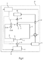
- FIG 4 shows a sectional side view of a Marshsgar réelle in the form of a steam oven 21.
- the steam oven 21 is similar to the steam oven 1 constructed, differs from this, however, by the presence of a permanently installed in the steam oven 21 intermediate memory 22nd
- first 3/2-way valve 23 instead of the shut-off valve 13 is present.
- the first 3/2-way valve 23 opens a connection between the evaporator shell 10 and the first tank 6 and blocks the connection between the evaporator shell 10 and the second tank 12.
- the first 3/2-way valve 23 closes the connection between the evaporator shell 10 and the first tank 6 and opens the connection between the evaporator shell 10 and the second tank 12.
- a second 3/2-way valve 24 is present.
- the second 3/2-way valve 24 opens a connection between the first tank 6 and the cooking chamber 2 and blocks the connection to the buffer 22.
- liquid can be pumped from the first tank 6 into the cooking chamber 2.
- the second 3/2-way valve 24 blocks the connection between the first tank 6 and the cooking chamber 2 and opens the connection between the first tank 6 and the buffer 22. This allows liquid from the first tank 6 in the Cache 22 are pumped.
- the filling volume of the buffer 22 is in particular at least as large as the filling volume of the first tank 6, but in principle need not be.
- a sequence of the intermediate storage 22 is connected via a shut-off valve 25 to the cooking chamber 2, in particular to the nozzle 8.
- This embodiment provides the advantage that now liquid from the cooking chamber 2 is recirculated, as will be shown in more detail below.
- step S6 all the clear water from the first tank 6 is pumped into the buffer 22, for which purpose the second 3/2-way valve 24 is in the second switching position.
- the shut-off valve 25 water from the buffer 22 can be discharged in portions into the cooking chamber 2, e.g. for steps S4, S8 and - if performed - S12.
- liquid in the cooking chamber 2 can now be circulated by actuating the pump 7. If the 3/2-way valves 23 and 24 are in their first switching positions, liquid present in the evaporator bowl 10 can flow into the first tank 6 and be pumped directly back into the cooking chamber 2 by the pump 7.
- the steam oven 21 then provides a liquid circuit, the cooking chamber 2, the first tank 6 and the pump 7 being parts thereof.
- An improved distribution of the liquid in the cooking chamber 2 is achieved during the circulation by the provision of the nozzle 8, through which the liquid is distributed over a large area in the cooking chamber 2.
- a larger amount of detergent can be used as in the evaporator shell 10 fits.
- the 3/2-way valve 23 can be switched to the second switching position.
- the pump 7 After switching the 3/2-way valve 23 to run in the second switching position for a while.
- the circulation circuit can also pass the first tank 6, for example analogously to Figure 3 ,
- the circulation circuit can also have a separate pump.
- Figure 5 shows a sectional side view of a household cooking appliance in the form of a steam oven 31st
- the steam oven 31 is constructed similar to the steam oven 21, but differs from the steam oven 1 by the absence of the second tank 12.
- the first tank 6 is now also provided as the user-emptied tank.
- a simple shut-off valve 32 is provided, which is open for circulating the liquid and for discharging the liquid in the first tank 6.
- the cooking chamber 2 can generally be treated successively by more than two treatment agents.
- Steps S1 and S2 are also executed in reverse order.
- the evaporator bowl may be missing in the cooking chamber and instead a steam generator may be present, in particular outside the cooking chamber.
- the steam generator for example, have the buffer as a liquid storage and evaporate located in the buffer liquid for introduction into the cooking chamber.
- a pump for pumping out the water from the first tank may be present, for example, a pump for pumping out the water from the first tank and a pump for circulating. This can be advantageous since these two functions can have different technical requirements.
- steam generator instead of the evaporator shell arranged outside the cooking chamber steam generator may be present. This can e.g. be arranged between a pressure side of the pump and the cooking chamber or between the buffer and the cooking chamber. Also, the cache may be part of the steam generator.
- a number may include exactly the specified number as well as a usual tolerance range, as long as this is not explicitly excluded.
Landscapes
- Chemical & Material Sciences (AREA)
- Engineering & Computer Science (AREA)
- Chemical Kinetics & Catalysis (AREA)
- Combustion & Propulsion (AREA)
- Mechanical Engineering (AREA)
- General Engineering & Computer Science (AREA)
- Commercial Cooking Devices (AREA)
- Cookers (AREA)
Priority Applications (1)
| Application Number | Priority Date | Filing Date | Title |
|---|---|---|---|
| EP16158065.9A EP3076086B1 (fr) | 2015-03-30 | 2016-03-01 | Appareil de cuisson menager et procede de fonctionnement d'un appareil de cuisson menager |
Applications Claiming Priority (2)
| Application Number | Priority Date | Filing Date | Title |
|---|---|---|---|
| EP15290087 | 2015-03-30 | ||
| EP16158065.9A EP3076086B1 (fr) | 2015-03-30 | 2016-03-01 | Appareil de cuisson menager et procede de fonctionnement d'un appareil de cuisson menager |
Publications (2)
| Publication Number | Publication Date |
|---|---|
| EP3076086A1 true EP3076086A1 (fr) | 2016-10-05 |
| EP3076086B1 EP3076086B1 (fr) | 2021-08-04 |
Family
ID=52997370
Family Applications (1)
| Application Number | Title | Priority Date | Filing Date |
|---|---|---|---|
| EP16158065.9A Active EP3076086B1 (fr) | 2015-03-30 | 2016-03-01 | Appareil de cuisson menager et procede de fonctionnement d'un appareil de cuisson menager |
Country Status (1)
| Country | Link |
|---|---|
| EP (1) | EP3076086B1 (fr) |
Cited By (3)
| Publication number | Priority date | Publication date | Assignee | Title |
|---|---|---|---|---|
| WO2020224965A1 (fr) * | 2019-05-03 | 2020-11-12 | BSH Hausgeräte GmbH | Appareil de traitement à la vapeur et procédé pour faire fonctionner un appareil de traitement à la vapeur |
| DE102020204203A1 (de) | 2020-03-31 | 2021-09-30 | BSH Hausgeräte GmbH | Haushalts-Dampfbehandlungsgerät und Verfahren zum Reinigen eines Verdampfers |
| EP4033155A1 (fr) | 2021-01-26 | 2022-07-27 | BSH Hausgeräte GmbH | Mise en oeuvre d'un processus de nettoyage d'un appareil électroménager contenant de l'eau |
Citations (5)
| Publication number | Priority date | Publication date | Assignee | Title |
|---|---|---|---|---|
| DE102006025508A1 (de) * | 2005-06-01 | 2006-12-07 | Sinnotec Entwicklungsgesellschaft Ltd. | Reinigungssystem zum Reinigen eines Back- oder Kombidämpfer-Geräts |
| EP2273200A1 (fr) | 2009-07-10 | 2011-01-12 | Rational AG | Appareil de cuisson doté d'un raccordement d'eau multiple et d'une sélection d'eau automatique en fonction d'un programme de cuisson ou de nettoyage |
| DE102010017177A1 (de) * | 2010-05-31 | 2011-12-01 | Debag Deutsche Backofenbau Gmbh | Einrichtung zur Wärmebehandlung von Lebensmitteln |
| DE102011010283A1 (de) | 2011-02-03 | 2012-08-09 | i-clean Technologies GmbH | Verfahren zur Reinigung eines Haushalts-Gargerätes |
| DE102011017021A1 (de) * | 2011-04-14 | 2012-10-18 | Jaroslav Klouda | Reinigungsvorrichtung für ein Gar- und/oder Back- und/oder Gär- und/oder Grillgerät |
Family Cites Families (2)
| Publication number | Priority date | Publication date | Assignee | Title |
|---|---|---|---|---|
| DE10060204B4 (de) * | 2000-11-28 | 2004-04-29 | Wiesheu Gmbh | Reinigungssystem für einen Ofen und Verfahren zur Ofenreinigung |
| DE102010039515A1 (de) * | 2010-08-19 | 2012-02-23 | BSH Bosch und Siemens Hausgeräte GmbH | Dampfgargerätvorrichtung |
-
2016
- 2016-03-01 EP EP16158065.9A patent/EP3076086B1/fr active Active
Patent Citations (5)
| Publication number | Priority date | Publication date | Assignee | Title |
|---|---|---|---|---|
| DE102006025508A1 (de) * | 2005-06-01 | 2006-12-07 | Sinnotec Entwicklungsgesellschaft Ltd. | Reinigungssystem zum Reinigen eines Back- oder Kombidämpfer-Geräts |
| EP2273200A1 (fr) | 2009-07-10 | 2011-01-12 | Rational AG | Appareil de cuisson doté d'un raccordement d'eau multiple et d'une sélection d'eau automatique en fonction d'un programme de cuisson ou de nettoyage |
| DE102010017177A1 (de) * | 2010-05-31 | 2011-12-01 | Debag Deutsche Backofenbau Gmbh | Einrichtung zur Wärmebehandlung von Lebensmitteln |
| DE102011010283A1 (de) | 2011-02-03 | 2012-08-09 | i-clean Technologies GmbH | Verfahren zur Reinigung eines Haushalts-Gargerätes |
| DE102011017021A1 (de) * | 2011-04-14 | 2012-10-18 | Jaroslav Klouda | Reinigungsvorrichtung für ein Gar- und/oder Back- und/oder Gär- und/oder Grillgerät |
Cited By (8)
| Publication number | Priority date | Publication date | Assignee | Title |
|---|---|---|---|---|
| WO2020224965A1 (fr) * | 2019-05-03 | 2020-11-12 | BSH Hausgeräte GmbH | Appareil de traitement à la vapeur et procédé pour faire fonctionner un appareil de traitement à la vapeur |
| CN113728199A (zh) * | 2019-05-03 | 2021-11-30 | Bsh家用电器有限公司 | 蒸汽处理器具和用于运行蒸汽处理器具的方法 |
| US20220154925A1 (en) * | 2019-05-03 | 2022-05-19 | BSH Hausgeräte GmbH | Steam treatment appliance and method for operating a steam treatment |
| CN113728199B (zh) * | 2019-05-03 | 2024-04-09 | Bsh家用电器有限公司 | 蒸汽处理器具和用于运行蒸汽处理器具的方法 |
| US12253258B2 (en) | 2019-05-03 | 2025-03-18 | BSH Hausgeräte GmbH | Steam treatment appliance |
| DE102020204203A1 (de) | 2020-03-31 | 2021-09-30 | BSH Hausgeräte GmbH | Haushalts-Dampfbehandlungsgerät und Verfahren zum Reinigen eines Verdampfers |
| EP4033155A1 (fr) | 2021-01-26 | 2022-07-27 | BSH Hausgeräte GmbH | Mise en oeuvre d'un processus de nettoyage d'un appareil électroménager contenant de l'eau |
| DE102021200678A1 (de) | 2021-01-26 | 2022-07-28 | BSH Hausgeräte GmbH | Durchführen eines Reinigungsablaufs eines wasserführenden Haushaltsgeräts |
Also Published As
| Publication number | Publication date |
|---|---|
| EP3076086B1 (fr) | 2021-08-04 |
Similar Documents
| Publication | Publication Date | Title |
|---|---|---|
| EP1953458B1 (fr) | Procédé de nettoyage d'un appareil de cuisson | |
| EP0383327B1 (fr) | Chaudière à vapeur avec détartrage pour appareil de cuisson | |
| EP1297907B1 (fr) | Couvercle pour appareil de cuisson comportant un dispositif de nettoyage et procédé de nettoyage | |
| DE102007048567B4 (de) | Verfahren zur Reinigung eines Systems, bestehend aus einem Tank und einem Durchlauferhitzer, sowie System | |
| EP1209419B1 (fr) | Dispositif et méthode de nettoyage d'un four de cuisson | |
| EP2366315B1 (fr) | Système de production de vapeur pour un appareil ménager et procédé de fonctionnement d'un système de production de vapeur | |
| DE10259829B4 (de) | Verfahren zum Entkalken von Dampferzeugern für Gargeräte | |
| DE102021114666B4 (de) | Gargerät für die Großküche mit Fettabsaugeinrichtung, Fettabsaugeinrichtung sowie Verfahren zum Betreiben eines solchen Gargeräts mit Fettabsaugung | |
| EP1364166A1 (fr) | Dispositif et procede pour nettoyer un appareil de cuisson | |
| WO2007098732A2 (fr) | Procédé de nettoyage d'un appareil de cuisson, et appareil de cuisson correspondant | |
| DE112014004758T5 (de) | Backofen für die Gastronomieindustrie mit einer Vorrichtung zum Zuführen des Reinigungsmittels zum Waschsystem der Backkammer | |
| EP2271375A1 (fr) | Appareil et procédé pour désinfecter, stériliser et/ou entretenir des instruments médicaux, notamment dentaires | |
| EP3076086B1 (fr) | Appareil de cuisson menager et procede de fonctionnement d'un appareil de cuisson menager | |
| EP2273200A1 (fr) | Appareil de cuisson doté d'un raccordement d'eau multiple et d'une sélection d'eau automatique en fonction d'un programme de cuisson ou de nettoyage | |
| CH711596B1 (de) | Reinigen eines Haushaltgeräts. | |
| WO2016155963A1 (fr) | Mise en œuvre d'un cycle de nettoyage d'un appareil de cuisson | |
| DE10033479A1 (de) | Wasserspareinrichtung mit Pumpe für Sanitärduschen | |
| DE102014209732A1 (de) | Reinigen wasserführender Komponenten eines Haushaltsgeräts | |
| EP3599421B1 (fr) | Système de nettoyage destiné au nettoyage de l'espace de cuisson d'un appareil de cuisson | |
| EP2476961A1 (fr) | Appareil de cuisson | |
| DE102009054161B4 (de) | Vorrichtung zum Reinigen und Desinfizieren von Reinigungsgut und Verfahren zur Desinfektion einer Vorrichtung der vorgenannten Art | |
| DE102021129609B4 (de) | Geschirrreinigungsautomat zum Reinigen von Küchenutensilien und Betriebsverfahren für den Geschirrreinigungsautomaten | |
| EP4282549B1 (fr) | Dispositif et procédé d'hydrolyse alcaline des cadavres et/ou de carcasses | |
| WO2008101774A2 (fr) | Dispositif pour faire bouillir de l'eau ayant une fonction de stérilisation et procédé de traitement d'eau | |
| DE3824601A1 (de) | Vorrichtung zum einbringen von wirkstoffen in saunakabinen |
Legal Events
| Date | Code | Title | Description |
|---|---|---|---|
| PUAI | Public reference made under article 153(3) epc to a published international application that has entered the european phase |
Free format text: ORIGINAL CODE: 0009012 |
|
| AK | Designated contracting states |
Kind code of ref document: A1 Designated state(s): AL AT BE BG CH CY CZ DE DK EE ES FI FR GB GR HR HU IE IS IT LI LT LU LV MC MK MT NL NO PL PT RO RS SE SI SK SM TR |
|
| AX | Request for extension of the european patent |
Extension state: BA ME |
|
| STAA | Information on the status of an ep patent application or granted ep patent |
Free format text: STATUS: REQUEST FOR EXAMINATION WAS MADE |
|
| 17P | Request for examination filed |
Effective date: 20170405 |
|
| RBV | Designated contracting states (corrected) |
Designated state(s): AL AT BE BG CH CY CZ DE DK EE ES FI FR GB GR HR HU IE IS IT LI LT LU LV MC MK MT NL NO PL PT RO RS SE SI SK SM TR |
|
| STAA | Information on the status of an ep patent application or granted ep patent |
Free format text: STATUS: EXAMINATION IS IN PROGRESS |
|
| 17Q | First examination report despatched |
Effective date: 20181121 |
|
| GRAP | Despatch of communication of intention to grant a patent |
Free format text: ORIGINAL CODE: EPIDOSNIGR1 |
|
| STAA | Information on the status of an ep patent application or granted ep patent |
Free format text: STATUS: GRANT OF PATENT IS INTENDED |
|
| INTG | Intention to grant announced |
Effective date: 20200917 |
|
| GRAJ | Information related to disapproval of communication of intention to grant by the applicant or resumption of examination proceedings by the epo deleted |
Free format text: ORIGINAL CODE: EPIDOSDIGR1 |
|
| STAA | Information on the status of an ep patent application or granted ep patent |
Free format text: STATUS: EXAMINATION IS IN PROGRESS |
|
| INTC | Intention to grant announced (deleted) | ||
| GRAP | Despatch of communication of intention to grant a patent |
Free format text: ORIGINAL CODE: EPIDOSNIGR1 |
|
| STAA | Information on the status of an ep patent application or granted ep patent |
Free format text: STATUS: GRANT OF PATENT IS INTENDED |
|
| INTG | Intention to grant announced |
Effective date: 20210323 |
|
| GRAS | Grant fee paid |
Free format text: ORIGINAL CODE: EPIDOSNIGR3 |
|
| GRAA | (expected) grant |
Free format text: ORIGINAL CODE: 0009210 |
|
| STAA | Information on the status of an ep patent application or granted ep patent |
Free format text: STATUS: THE PATENT HAS BEEN GRANTED |
|
| AK | Designated contracting states |
Kind code of ref document: B1 Designated state(s): AL AT BE BG CH CY CZ DE DK EE ES FI FR GB GR HR HU IE IS IT LI LT LU LV MC MK MT NL NO PL PT RO RS SE SI SK SM TR |
|
| REG | Reference to a national code |
Ref country code: GB Ref legal event code: FG4D Free format text: NOT ENGLISH |
|
| REG | Reference to a national code |
Ref country code: AT Ref legal event code: REF Ref document number: 1417350 Country of ref document: AT Kind code of ref document: T Effective date: 20210815 |
|
| REG | Reference to a national code |
Ref country code: CH Ref legal event code: EP |
|
| REG | Reference to a national code |
Ref country code: DE Ref legal event code: R096 Ref document number: 502016013525 Country of ref document: DE |
|
| REG | Reference to a national code |
Ref country code: NL Ref legal event code: FP |
|
| REG | Reference to a national code |
Ref country code: IE Ref legal event code: FG4D Free format text: LANGUAGE OF EP DOCUMENT: GERMAN |
|
| REG | Reference to a national code |
Ref country code: LT Ref legal event code: MG9D |
|
| PG25 | Lapsed in a contracting state [announced via postgrant information from national office to epo] |
Ref country code: FI Free format text: LAPSE BECAUSE OF FAILURE TO SUBMIT A TRANSLATION OF THE DESCRIPTION OR TO PAY THE FEE WITHIN THE PRESCRIBED TIME-LIMIT Effective date: 20210804 Ref country code: ES Free format text: LAPSE BECAUSE OF FAILURE TO SUBMIT A TRANSLATION OF THE DESCRIPTION OR TO PAY THE FEE WITHIN THE PRESCRIBED TIME-LIMIT Effective date: 20210804 Ref country code: PT Free format text: LAPSE BECAUSE OF FAILURE TO SUBMIT A TRANSLATION OF THE DESCRIPTION OR TO PAY THE FEE WITHIN THE PRESCRIBED TIME-LIMIT Effective date: 20211206 Ref country code: NO Free format text: LAPSE BECAUSE OF FAILURE TO SUBMIT A TRANSLATION OF THE DESCRIPTION OR TO PAY THE FEE WITHIN THE PRESCRIBED TIME-LIMIT Effective date: 20211104 Ref country code: BG Free format text: LAPSE BECAUSE OF FAILURE TO SUBMIT A TRANSLATION OF THE DESCRIPTION OR TO PAY THE FEE WITHIN THE PRESCRIBED TIME-LIMIT Effective date: 20211104 Ref country code: LT Free format text: LAPSE BECAUSE OF FAILURE TO SUBMIT A TRANSLATION OF THE DESCRIPTION OR TO PAY THE FEE WITHIN THE PRESCRIBED TIME-LIMIT Effective date: 20210804 Ref country code: SE Free format text: LAPSE BECAUSE OF FAILURE TO SUBMIT A TRANSLATION OF THE DESCRIPTION OR TO PAY THE FEE WITHIN THE PRESCRIBED TIME-LIMIT Effective date: 20210804 Ref country code: RS Free format text: LAPSE BECAUSE OF FAILURE TO SUBMIT A TRANSLATION OF THE DESCRIPTION OR TO PAY THE FEE WITHIN THE PRESCRIBED TIME-LIMIT Effective date: 20210804 Ref country code: HR Free format text: LAPSE BECAUSE OF FAILURE TO SUBMIT A TRANSLATION OF THE DESCRIPTION OR TO PAY THE FEE WITHIN THE PRESCRIBED TIME-LIMIT Effective date: 20210804 |
|
| PG25 | Lapsed in a contracting state [announced via postgrant information from national office to epo] |
Ref country code: PL Free format text: LAPSE BECAUSE OF FAILURE TO SUBMIT A TRANSLATION OF THE DESCRIPTION OR TO PAY THE FEE WITHIN THE PRESCRIBED TIME-LIMIT Effective date: 20210804 Ref country code: LV Free format text: LAPSE BECAUSE OF FAILURE TO SUBMIT A TRANSLATION OF THE DESCRIPTION OR TO PAY THE FEE WITHIN THE PRESCRIBED TIME-LIMIT Effective date: 20210804 Ref country code: GR Free format text: LAPSE BECAUSE OF FAILURE TO SUBMIT A TRANSLATION OF THE DESCRIPTION OR TO PAY THE FEE WITHIN THE PRESCRIBED TIME-LIMIT Effective date: 20211105 |
|
| PG25 | Lapsed in a contracting state [announced via postgrant information from national office to epo] |
Ref country code: DK Free format text: LAPSE BECAUSE OF FAILURE TO SUBMIT A TRANSLATION OF THE DESCRIPTION OR TO PAY THE FEE WITHIN THE PRESCRIBED TIME-LIMIT Effective date: 20210804 |
|
| REG | Reference to a national code |
Ref country code: DE Ref legal event code: R097 Ref document number: 502016013525 Country of ref document: DE |
|
| PG25 | Lapsed in a contracting state [announced via postgrant information from national office to epo] |
Ref country code: SM Free format text: LAPSE BECAUSE OF FAILURE TO SUBMIT A TRANSLATION OF THE DESCRIPTION OR TO PAY THE FEE WITHIN THE PRESCRIBED TIME-LIMIT Effective date: 20210804 Ref country code: SK Free format text: LAPSE BECAUSE OF FAILURE TO SUBMIT A TRANSLATION OF THE DESCRIPTION OR TO PAY THE FEE WITHIN THE PRESCRIBED TIME-LIMIT Effective date: 20210804 Ref country code: RO Free format text: LAPSE BECAUSE OF FAILURE TO SUBMIT A TRANSLATION OF THE DESCRIPTION OR TO PAY THE FEE WITHIN THE PRESCRIBED TIME-LIMIT Effective date: 20210804 Ref country code: EE Free format text: LAPSE BECAUSE OF FAILURE TO SUBMIT A TRANSLATION OF THE DESCRIPTION OR TO PAY THE FEE WITHIN THE PRESCRIBED TIME-LIMIT Effective date: 20210804 Ref country code: CZ Free format text: LAPSE BECAUSE OF FAILURE TO SUBMIT A TRANSLATION OF THE DESCRIPTION OR TO PAY THE FEE WITHIN THE PRESCRIBED TIME-LIMIT Effective date: 20210804 Ref country code: AL Free format text: LAPSE BECAUSE OF FAILURE TO SUBMIT A TRANSLATION OF THE DESCRIPTION OR TO PAY THE FEE WITHIN THE PRESCRIBED TIME-LIMIT Effective date: 20210804 |
|
| PLBE | No opposition filed within time limit |
Free format text: ORIGINAL CODE: 0009261 |
|
| STAA | Information on the status of an ep patent application or granted ep patent |
Free format text: STATUS: NO OPPOSITION FILED WITHIN TIME LIMIT |
|
| 26N | No opposition filed |
Effective date: 20220506 |
|
| PG25 | Lapsed in a contracting state [announced via postgrant information from national office to epo] |
Ref country code: IT Free format text: LAPSE BECAUSE OF FAILURE TO SUBMIT A TRANSLATION OF THE DESCRIPTION OR TO PAY THE FEE WITHIN THE PRESCRIBED TIME-LIMIT Effective date: 20210804 |
|
| PG25 | Lapsed in a contracting state [announced via postgrant information from national office to epo] |
Ref country code: SI Free format text: LAPSE BECAUSE OF FAILURE TO SUBMIT A TRANSLATION OF THE DESCRIPTION OR TO PAY THE FEE WITHIN THE PRESCRIBED TIME-LIMIT Effective date: 20210804 |
|
| PG25 | Lapsed in a contracting state [announced via postgrant information from national office to epo] |
Ref country code: MC Free format text: LAPSE BECAUSE OF FAILURE TO SUBMIT A TRANSLATION OF THE DESCRIPTION OR TO PAY THE FEE WITHIN THE PRESCRIBED TIME-LIMIT Effective date: 20210804 |
|
| REG | Reference to a national code |
Ref country code: BE Ref legal event code: MM Effective date: 20220331 |
|
| PG25 | Lapsed in a contracting state [announced via postgrant information from national office to epo] |
Ref country code: LU Free format text: LAPSE BECAUSE OF NON-PAYMENT OF DUE FEES Effective date: 20220301 Ref country code: IE Free format text: LAPSE BECAUSE OF NON-PAYMENT OF DUE FEES Effective date: 20220301 |
|
| PG25 | Lapsed in a contracting state [announced via postgrant information from national office to epo] |
Ref country code: BE Free format text: LAPSE BECAUSE OF NON-PAYMENT OF DUE FEES Effective date: 20220331 |
|
| REG | Reference to a national code |
Ref country code: AT Ref legal event code: MM01 Ref document number: 1417350 Country of ref document: AT Kind code of ref document: T Effective date: 20220301 |
|
| PG25 | Lapsed in a contracting state [announced via postgrant information from national office to epo] |
Ref country code: AT Free format text: LAPSE BECAUSE OF NON-PAYMENT OF DUE FEES Effective date: 20220301 |
|
| PG25 | Lapsed in a contracting state [announced via postgrant information from national office to epo] |
Ref country code: HU Free format text: LAPSE BECAUSE OF FAILURE TO SUBMIT A TRANSLATION OF THE DESCRIPTION OR TO PAY THE FEE WITHIN THE PRESCRIBED TIME-LIMIT; INVALID AB INITIO Effective date: 20160301 |
|
| PG25 | Lapsed in a contracting state [announced via postgrant information from national office to epo] |
Ref country code: MK Free format text: LAPSE BECAUSE OF FAILURE TO SUBMIT A TRANSLATION OF THE DESCRIPTION OR TO PAY THE FEE WITHIN THE PRESCRIBED TIME-LIMIT Effective date: 20210804 Ref country code: CY Free format text: LAPSE BECAUSE OF FAILURE TO SUBMIT A TRANSLATION OF THE DESCRIPTION OR TO PAY THE FEE WITHIN THE PRESCRIBED TIME-LIMIT Effective date: 20210804 |
|
| PG25 | Lapsed in a contracting state [announced via postgrant information from national office to epo] |
Ref country code: MT Free format text: LAPSE BECAUSE OF FAILURE TO SUBMIT A TRANSLATION OF THE DESCRIPTION OR TO PAY THE FEE WITHIN THE PRESCRIBED TIME-LIMIT Effective date: 20210804 |
|
| PGFP | Annual fee paid to national office [announced via postgrant information from national office to epo] |
Ref country code: CH Payment date: 20250401 Year of fee payment: 10 |
|
| PG25 | Lapsed in a contracting state [announced via postgrant information from national office to epo] |
Ref country code: TR Free format text: LAPSE BECAUSE OF FAILURE TO SUBMIT A TRANSLATION OF THE DESCRIPTION OR TO PAY THE FEE WITHIN THE PRESCRIBED TIME-LIMIT Effective date: 20210804 |
|
| REG | Reference to a national code |
Ref country code: CH Ref legal event code: U11 Free format text: ST27 STATUS EVENT CODE: U-0-0-U10-U11 (AS PROVIDED BY THE NATIONAL OFFICE) Effective date: 20260401 |
|
| PGFP | Annual fee paid to national office [announced via postgrant information from national office to epo] |
Ref country code: GB Payment date: 20260324 Year of fee payment: 11 |
|
| PGFP | Annual fee paid to national office [announced via postgrant information from national office to epo] |
Ref country code: DE Payment date: 20260331 Year of fee payment: 11 |
|
| PGFP | Annual fee paid to national office [announced via postgrant information from national office to epo] |
Ref country code: NL Payment date: 20260323 Year of fee payment: 11 |
|
| PGFP | Annual fee paid to national office [announced via postgrant information from national office to epo] |
Ref country code: FR Payment date: 20260324 Year of fee payment: 11 |