EP3076101B1 - Échangeur de chaleur et ensemble constitué d'un brûleur et d'un échangeur de chaleur - Google Patents
Échangeur de chaleur et ensemble constitué d'un brûleur et d'un échangeur de chaleur Download PDFInfo
- Publication number
- EP3076101B1 EP3076101B1 EP16159342.1A EP16159342A EP3076101B1 EP 3076101 B1 EP3076101 B1 EP 3076101B1 EP 16159342 A EP16159342 A EP 16159342A EP 3076101 B1 EP3076101 B1 EP 3076101B1
- Authority
- EP
- European Patent Office
- Prior art keywords
- pipes
- burner
- heat exchanger
- group
- pattern
- Prior art date
- Legal status (The legal status is an assumption and is not a legal conclusion. Google has not performed a legal analysis and makes no representation as to the accuracy of the status listed.)
- Active
Links
Images


Classifications
-
- F—MECHANICAL ENGINEERING; LIGHTING; HEATING; WEAPONS; BLASTING
- F24—HEATING; RANGES; VENTILATING
- F24H—FLUID HEATERS, e.g. WATER OR AIR HEATERS, HAVING HEAT-GENERATING MEANS, e.g. HEAT PUMPS, IN GENERAL
- F24H1/00—Water heaters, e.g. boilers, continuous-flow heaters or water-storage heaters
- F24H1/22—Water heaters other than continuous-flow or water-storage heaters, e.g. water heaters for central heating
- F24H1/40—Water heaters other than continuous-flow or water-storage heaters, e.g. water heaters for central heating with water tube or tubes
- F24H1/406—Water heaters other than continuous-flow or water-storage heaters, e.g. water heaters for central heating with water tube or tubes the tubes forming a membrane wall
-
- F—MECHANICAL ENGINEERING; LIGHTING; HEATING; WEAPONS; BLASTING
- F28—HEAT EXCHANGE IN GENERAL
- F28D—HEAT-EXCHANGE APPARATUS, NOT PROVIDED FOR IN ANOTHER SUBCLASS, IN WHICH THE HEAT-EXCHANGE MEDIA DO NOT COME INTO DIRECT CONTACT
- F28D21/00—Heat-exchange apparatus not covered by any of the groups F28D1/00 - F28D20/00
- F28D21/0001—Recuperative heat exchangers
- F28D21/0003—Recuperative heat exchangers the heat being recuperated from exhaust gases
-
- F—MECHANICAL ENGINEERING; LIGHTING; HEATING; WEAPONS; BLASTING
- F28—HEAT EXCHANGE IN GENERAL
- F28D—HEAT-EXCHANGE APPARATUS, NOT PROVIDED FOR IN ANOTHER SUBCLASS, IN WHICH THE HEAT-EXCHANGE MEDIA DO NOT COME INTO DIRECT CONTACT
- F28D7/00—Heat-exchange apparatus having stationary tubular conduit assemblies for both heat-exchange media, the media being in contact with different sides of a conduit wall
- F28D7/0041—Heat-exchange apparatus having stationary tubular conduit assemblies for both heat-exchange media, the media being in contact with different sides of a conduit wall the conduits for only one medium being tubes having parts touching each other or tubes assembled in panel form
-
- F—MECHANICAL ENGINEERING; LIGHTING; HEATING; WEAPONS; BLASTING
- F28—HEAT EXCHANGE IN GENERAL
- F28D—HEAT-EXCHANGE APPARATUS, NOT PROVIDED FOR IN ANOTHER SUBCLASS, IN WHICH THE HEAT-EXCHANGE MEDIA DO NOT COME INTO DIRECT CONTACT
- F28D7/00—Heat-exchange apparatus having stationary tubular conduit assemblies for both heat-exchange media, the media being in contact with different sides of a conduit wall
- F28D7/16—Heat-exchange apparatus having stationary tubular conduit assemblies for both heat-exchange media, the media being in contact with different sides of a conduit wall the conduits being arranged in parallel spaced relation
- F28D7/163—Heat-exchange apparatus having stationary tubular conduit assemblies for both heat-exchange media, the media being in contact with different sides of a conduit wall the conduits being arranged in parallel spaced relation with conduit assemblies having a particular shape, e.g. square or annular; with assemblies of conduits having different geometrical features; with multiple groups of conduits connected in series or parallel and arranged inside common casing
- F28D7/1638—Heat-exchange apparatus having stationary tubular conduit assemblies for both heat-exchange media, the media being in contact with different sides of a conduit wall the conduits being arranged in parallel spaced relation with conduit assemblies having a particular shape, e.g. square or annular; with assemblies of conduits having different geometrical features; with multiple groups of conduits connected in series or parallel and arranged inside common casing with particular pattern of flow or the heat exchange medium flowing inside the conduits assemblies, e.g. change of flow direction from one conduit assembly to another one
-
- F—MECHANICAL ENGINEERING; LIGHTING; HEATING; WEAPONS; BLASTING
- F28—HEAT EXCHANGE IN GENERAL
- F28F—DETAILS OF HEAT-EXCHANGE AND HEAT-TRANSFER APPARATUS, OF GENERAL APPLICATION
- F28F2210/00—Heat exchange conduits
- F28F2210/08—Assemblies of conduits having different features
Definitions
- the invention relates to a heat exchanger, comprising:
- Such a heat exchanger is known from European patent EP-B1-0687870 in the name of the same applicant. It is an object to improve the heat exchanger described in EP-B1-0687870 .
- a heat exchanger is also known from EP 1 243 866 A1 .
- This document discloses in a condensation boiler of the type comprising a plurality of pipes defining a water flow path between a return section from a heating plant to a delivery section to the heating plant, at least two covers mounted at an end of the plurality of pipes and provided internally with dividing walls that realize connecting chambers between the pipes and define the conformation of the water flow path.
- the connecting chambers also serve the function of front wall of a wet combustion chamber.
- said receiving space is arranged between at least a part of the pipes of the first pattern located near the open end of the U-shape body in such a manner that in use at least a part of the pipes of the first pattern surround a flame provided by said burner.
- An advantage of this embodiment is that the casing is protected from the heat of the flame by said pipes of the first pattern that surround said flame.
- the flame was present in an area not bounded by pipes. Practically the heat exchanger therefore had a sealing arranged to protect the casing from the heat, which sealing is quite expensive.
- An advantage of this embodiment is therefore that no or less sealing is required, thereby reducing the costs of the heat exchanger.
- a distance between all pairs of adjacent pipes of each leg of the first pattern is maximally 0.1 mm.
- said distance is defined as the distance between the adjacent outer surfaces of each pair of adjacent pipes.
- said heat exchanger comprises a sealing arranged between the outer surface of the pipes arranged at a first end of each leg of the first pattern near the open end of the U-shape body and the substantially U-shaped body.
- the distance between the legs of the U-shape body and the pipes of the first pattern is maximally 1.0 mm, preferably maximally 0.4 mm.
- said distance is defined as the distance between the outer surfaces of the pipes of the first pattern that are facing the U-shape body and the legs of the U-shape body.
- Relatively hot flue gas has a relatively large volume and vice versa.
- the flue gas coming from the burner has a relatively large flow rate as the flue gas is relatively hot, thereby requiring a relatively large surface area between adjacent pipes arranged near the burner space in order to have the velocity of the flue gas being maximally said value C.
- the pipes arranged near the outlet opening however require a smaller surface area there between in order to have the velocity of the flue gas being maximally said value C, as the flue gas is already cooled down to some extent by the heat exchanger and the flow rate is relatively small.
- An advantage of a substantially constant velocity of the flue gas throughout the heat exchanger is that such a substantially constant velocity reduces the pressure drop. It is therefore an advantage of this embodiment to arrange said second part of the pipes such that this formula is fulfilled.
- An advantage of this embodiment is that the heat exchanger is designed such that the distribution of the liquid flow over determined groups of pipes is chosen such that the quantity of heat Q discharged from the flue gas and transferred to the liquid flowing in each pipe is substantially constant anywhere in the heat exchanger.
- the pipes are exposed to less thermal stresses as the pipes are exposed to more or less similar heat transfer.
- the liquid flow through the pipes is optimized with respect to pressure drop and blockage of the pipes due to lime scale deposition is prevented by preventing the pipes from becoming too hot. This is especially advantageous in heat exchangers where a relatively large number of pipes with a relatively small throughflow area is used.
- At least one of the connecting means comprises a liquid distributor for substantially equally distributing liquid over pipes being connected to said connecting means.
- liquid distributor Without such a liquid distributor it is possible that the liquid is not equally distributed over the pipes connected to the connecting means. This way, some pipes with less liquid flowing there through can become too hot and thereby exposed to high thermal stresses.
- An advantage of the liquid distributor is therefore that the liquid is substantially equally distributed over pipes that are connected to said connecting means, thereby reducing the thermal stresses of the pipes.
- the second part of the pipes comprise at least three groups of pipes, wherein a first group located near the base of the U-shape body has a first, smallest diameter, wherein a second group located near the first group at a side of the first group opposite to the base of the U-shape has a second diameter, and wherein a third group located near the open end of the U-shape body has a third, largest diameter, which third group is located at a predetermined distance from the second group.
- An advantage of this arrangement of the pipes is that the third group is arranged nearest to the burner space.
- the flue gas coming from the burner is cooled down relatively fast by this third group of pipes arranged near the burner with relatively large diameter and thereby relatively large liquid flow, such that the production of NOx is efficiently reduced.
- said predetermined distance is present, such that over this distance the flue gas is substantially not cooled down and a relatively large time period is provided for the conversion of CO into CO 2 , such that the emission of CO is reduced and preferably prevented.
- said distance is preferably between 10 and 40mm, more preferably between 20 and 30mm. Said distance is defined between the outer surfaces of the row of pipes of the third group and the row of pipes of the second group arranged nearest to the third group and especially between the facing outer surfaces thereof.
- a part of the pipes of the first group is arranged at least partly between a part of the pipes of the second group.
- An advantage of such an arrangement is that the flow of flue gas along substantially the whole outer surface of the pipes arranged upstream of said part of pipes of the second group as seen in the direction of the flow of flue gases is enhanced.
- the invention also relates to an assembly of a heat exchanger according to any of the claims 1 - 7 and a burner, wherein the burner is arranged in said receiving space.
- the assembly comprises the heat exchanger according to at least claim 2, wherein the burner is arranged in said receiving space in such a manner that in use at least a part of the pipes of the first pattern surround a flame provided by said burner.
- said burner comprises a damper.
- Such a (Panel Helmholtz resonance) damper efficiently dampens any noise of the heat exchanger.
- said burner comprises a burner plate that is connected to or is integrally formed with said damper.
- An advantage of this embodiment is that the functions of the burner plate and the damper are combined in one integrally formed or connected element.
- said burner comprises a gas/air-mixture distribution plate that is connected to or integrally formed with said damper and/or burner plate.
- An advantage of this embodiment is that the functions of the burner plate and/or the damper and/or the gas/air-mixture distribution plate are combined in one integrally formed or connected element.
- said (Panel Helmholtz resonance) damper may be provided with through holes for distributing the gas/air-mixture, such that said damper functions also as said gas/air-mixture distribution plate.
- said assembly comprises a sealing that is provided between the casing and the gas/air-mixture distribution plate.
- Said gas/air-mixture distribution plate is arranged upstream of the burner plate and distributes the gas/air-mixture prior to passing though the burner plate.
- the gas/air-mixture distribution plate and the burner plate are connected or integrally formed in one element, the gas/air-mixture exiting the gas/air-mixture distribution plate cannot by-pass the burner plate.
- Said sealing prevents the gas/air-mixture from entering the burner room alongside said element comprising the gas/air-mixture distribution plate and the burner plate.
- the gas/air-mixture flowing through the gas/air chamber will cool down the gas/air chamber and the gas/air-mixture distribution plate/damper. The life time of the burner is hereby enhanced.
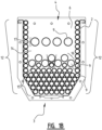
- FIGS 1A and 1B show a heat exchanger 1.
- Said heat exchanger 1 comprises a casing with a substantially U-shaped body 2 as seen in cross-section and extending in a longitudinal direction L.
- the base 3 of the body 2 arranged at the lower end of the body 2 comprises a gas outlet opening (not shown).
- the body 2 is open and comprises a receiving space 4 for receiving a burner (not shown).
- the flue gases from the burner flow downwards through the casing 1 and are discharged via said gas outlet opening.
- the body 2 comprises an end plate 6.
- a plurality of pipes 9 is arranged within said casing and is connected to said end plates 6, in particular to holes in said end plates 6.
- a liquid practically water flows though the pipes 9 for taking up heat from the flue gases, thereby heating the water and cooling the flue gases.
- Panels 7 are provided to cover the end plates 6.
- Each panel 7 comprises a plurality of hollow spaces 8, each hollow space 8 connecting at least two pipes 9 at each longitudinal end zone 5 of the body 2, such that liquid flowing through a first pipe 9 of the at least two pipes 9 is directed to the other pipe 9 of the at least two pipes 9. Liquid flowing through the pipes 9 thereby flows from the one longitudinal end zone 5 to the other longitudinal end zone 5 via the plurality of pipes 9 and hollow spaces 8.
- a water inlet 10 and a water outlet 11 are provided in one panel 7 at one longitudinal end zone 5, for feeding relatively cold water to the pipes 9 via the water inlet 10 and for discharging relatively hot water from the pipes 9 via the water outlet 11.
- Said hot water may be used for central heating or tap water.
- a first part of the pipes 9 is arranged in a first pattern 12 defining two legs of a substantially U-shape as seen in cross-section, said first pattern being arranged substantially parallel to legs of said U-shape body 2.
- the receiving space 4 for the burner is arranged between at least a part of the pipes 9 of the first pattern 12 located near the open end of the body 2 in such a manner that in use at least a part of the pipes 9 of the first pattern 12 surround a flame provided by said burner. This way, said part of the pipes 9 of the first pattern 12 protect the casing from the heat of the flame.
- a distance between all pairs of adjacent pipes 9 of each leg of the first pattern 12 is maximally 0.1 mm, thereby restricting the mass flow of flue gas that will flow through the spaces between adjacent pipes 9 to an area between the pipes of the legs of the first pattern 12 and the casing, such that the flue gas that will enter this area will be cooled down by the liquid in the pipes 9 to such an extent that the flue gas will have a relatively low temperature that is more or less similar to or slightly higher than the temperature of the walls of these pipes 9.
- the distance between the legs of the U-shape body 2 and the pipes 9 of the first pattern 12 is preferably maximally 1.0 mm, more preferably maximally 0.4 mm, thereby also contributing to the restriction of the mass flow of flue gas into this area and thereby contributing to the reduction in temperature to which the casing is exposed.
- a sealing 13 is arranged between the outer surface of the pipes 9 arranged at a first end of each leg of the first pattern 12 near the open end of the body 2 and the body 2, thereby sealing off the space there between and thereby preventing the flue gases from flowing in the area between the pipes 9 of the first pattern 12 and the casing via said space.
- a second part of said pipes 9 are arranged within a space 14 at least partly bounded by said first pattern 12.
- Relatively hot flue gas has a relatively large volume and vice versa.
- the flue gas coming from the burner arranged in the receiving space 4 has a relatively large flow rate as the flue gas is relatively hot, thereby requiring a relatively large surface area between adjacent pipes 9 arranged near the burner space in order to have the velocity of the flue gas being maximally said value C.
- the pipes 9 arranged near the outlet opening in the base 3 of the body 2 therefor require a smaller surface area there between in order to have the velocity of the flue gas being maximally said value C, as the flue gas is already cooled down to some extent by the heat exchanger and the flow rate is relatively small. This is shown in figure 1B , showing that the closer the pipes 9 are arranged to the burner arranged in the receiving space 4, the larger the surface area between the pipes 9.
- the second part of the pipes comprises three groups of pipes 9, wherein a first group 15 located near the base 3 of the body 2 has a first, smallest diameter, wherein a second group 16 located near the first group 15 at a side of the first group 15 opposite to the base 3 of body 2 has a second, intermediate diameter, and wherein a third group 17 located near the open end of the body 2 has a third, largest diameter.
- a third group 17 of pipes 9 has the largest diameter of the three groups, the flow rate of liquid flowing there through is also the largest of the three groups, thereby cooling down the flue gas coming from the burner relatively fast and efficiently reducing production of NO x .
- the pipes 9 of the second group 16 have an intermediate diameter adapted to the amount of heat to be absorbed from the already partly cooled down flue gases, and the pipes 9 of the first group 15 have the smallest diameter adapted to absorb heat from the more cooled down flue gases.
- a part of the pipes 9 of the first group 15, in particular three pipes 9 thereof, is arranged at least partly between a part of the pipes 9 of the second group 16, wherein said part of the pipes 9 of the first group 15 and said part of the pipes 9 of the second group 16 are arranged alternately in a direction substantially orthogonal to the direction of the flow of the flue gases.
- the flow of flue gas is directed along substantially the whole outer surface, in particular also along the lower surface, of the pipes 9 arranged directly upstream of said part of pipes 9 of the second group 16 as seen in the direction of the flow of flue gases.
- FIG. 2 schematically shows the distribution of the liquid flow through the pipes 9 of the heat exchanger. This shows that the pipes 9 are divided over in total twenty-two groups. Appointment of the pipes 9 to each group is established with said hollow spaces 8 that connect any desired number of selected pipes 9 to a specific group.
- Liquid enters the first group I via the liquid inlet 10 that is in medium through flow connection with group I and exits the last group XX via liquid outlet 11 that is in medium through flow connection with group XX.
- the liquid flows alternatingly between the two end zones 5 via the groups in sequential order, thus via group I to group II, from group II to group III, etc.
- the number of pipes 9 belonging to each group and the selection of pipes 9 belonging to each group may be chosen as desired.
- the selection and number of pipes 9 belonging to each group are chosen to fulfil a second formula:
- the liquid flow is distributed such that the quantity of heat Q discharged from the flue gas and transferred to the liquid flowing in each pipe is substantially constant anywhere in the heat exchanger.
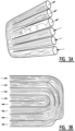
- Figures 3A and 3B show the effect of liquid distributors according to the invention.
- Said liquid distributors may be provided in any desired hollow space 8 for distributing the liquid over the pipes 9 connecting to that hollow space 8.
- Figure 3A shows a plurality of three pipes 9 of a group that are connected via a hollow space 8 to three pipes 9 of a subsequent group. The liquid tends to follow the largest curvature and thereby to enter the most outer pipe 9 of the three pipes of the subsequent group. The middle pipe therefor receives less liquid and will therefor become relative hot and exposed to high thermal stresses.
- each pipe 9 of a group is connected to a pipe 9 of the subsequent group. The liquid is thereby evenly distributed over the pipes 9 belonging to a specific group, independent of the location of the pipe 9.
- FIG 4 is a perspective view of a burner according to the invention.
- Said burner comprises a casing 18.
- an element comprising a ceramic burner plate 19 and a damper 21 that also functions as an aluminium gas/air mixture distribution plate and that is arranged upstream from the burner plate 19.
- An anorganic insulation material 20 is provided between the burner plate 19 and the damper/distribution plate 21.
- a sealing 22 is provided between the casing 18 and the damper/distribution plate 21, such that the gas/air-mixture is prevented from entering the burner room alongside said element comprising the damper/distribution plate 21and the burner plate 19.
- the gas/air-mixture exiting the damper/distribution plate 21 cannot by-pass the burner plate 19.
- the gas/air-mixture flowing through the gas/air chamber will cool down the gas/air chamber and the gas/air-mixture distribution plate/damper 21.
- the life time of the burner is hereby enhanced.
- Figure 5 shows an assembly of the heat exchanger of figures 1A , 1B and the burner of figure 4 .
- the U-shape body 2 and the panels 7 of the heat exchanger are shown, as well as the casing 18 of the burner.
- the burner is arranged such in the receiving space of the body 2, that the flames coming from the burner plate are surrounded by the upper pipes 9 of the legs of the first pattern 12 of pipes 9.
Landscapes
- Engineering & Computer Science (AREA)
- Physics & Mathematics (AREA)
- Thermal Sciences (AREA)
- Mechanical Engineering (AREA)
- General Engineering & Computer Science (AREA)
- Chemical & Material Sciences (AREA)
- Combustion & Propulsion (AREA)
- Geometry (AREA)
- Heat-Exchange Devices With Radiators And Conduit Assemblies (AREA)
Claims (13)
- Échangeur de chaleur (1), comprenant:- un carter (18), comprenant:- un corps sensiblement en forme de U (2) vu en coupe transversale et s'étendant dans une direction longitudinale, dans lequel une base (3) du corps en forme de U (2) comprend une ouverture de sortie de gaz et dans lequel une extrémité ouverte, opposée à la base (3), du corps en forme de U (2) comprend un espace de réception (4) destiné à recevoir un brûleur, et- deux plaques d'extrémité (6) agencées au niveau des deux zones d'extrémité longitudinales (5) dudit corps en forme de U (2);- une pluralité de tuyaux (9) agencés à l'intérieur dudit carter (18) et reliés aux plaques d'extrémité (6), à travers lesquels les tuyaux (9), lors de l'utilisation, peuvent laisser s'écouler un liquide;- une pluralité de moyens de raccordement pour fournir un liquide à travers un raccordement d'écoulement entre au moins deux tuyaux (9) au niveau de chaque zone d'extrémité longitudinale (5) dudit corps en forme de U (2), de telle sorte que le liquide s'écoulant à travers un premier tuyau (9) des au moins deux tuyaux (9) est dirigé vers l'autre tuyau (9) des au moins deux tuyaux (9),dans lequel une première partie des tuyaux (9) est agencée selon un premier modèle (12) définissant deux pattes d'une forme sensiblement en U vue en coupe transversale, ledit premier modèle (12) étant agencé sensiblement parallèlement aux pattes dudit corps en forme de U (2), etdans lequel une seconde partie des tuyaux (9) est agencée à l'intérieur d'un espace (14) au moins partiellement délimité par le premier modèle (12),caractérisé en ce qu'une distance entre toutes les paires de tuyaux adjacents (9) de chaque patte du premier modèle (12) est au maximum de 0,1 mm.
- Échangeur de chaleur (1) selon la revendication 1, dans lequel ledit espace de réception (4) est agencé entre au moins une partie des tuyaux (9) du premier modèle (12) situés près de l'extrémité ouverte du corps en forme de U (2) de manière que, lors de l'utilisation, au moins une partie des tuyaux (9) du premier modèle (12) entoure une flamme fournie par ledit brûleur.
- Échangeur de chaleur (1) selon l'une quelconque des revendications précédentes, comprenant un joint d'étanchéité (13) agencé entre la surface extérieure des tuyaux (9) agencés au niveau d'une première extrémité de chaque patte du premier modèle (12) près de l'extrémité ouverte du corps en forme de U (2) et le corps en forme de U (2).
- Échangeur de chaleur (1) selon l'une quelconque des revendications précédentes, dans lequel la distance entre les pattes du corps en forme de U (2) et les tuyaux (9) du premier modèle (12) est au maximum de 1,0 mm, de préférence au maximum de 0,4 mm.
- Échangeur de chaleur (1) selon l'une quelconque des revendications précédentes, dans lequel au moins l'un parmi les moyens de raccordement comprend un distributeur de liquide pour distribuer de manière sensiblement égale le liquide sur des tuyaux (9) raccordés auxdits moyens de raccordement.
- Échangeur de chaleur (1) selon l'une quelconque des revendications précédentes, dans lequel la seconde partie des tuyaux (9) comprend au moins trois groupes de tuyaux (9), dans lequel un premier groupe (15) situé près de la base (3) du corps en forme de U (2) présente un premier diamètre, le plus petit, dans lequel un deuxième groupe (16) situé près du premier groupe (15) sur un côté du premier groupe (15) opposé à la base (3) du corps en forme de U (2) présente un deuxième diamètre, et dans lequel un troisième groupe (17) situé près de l'extrémité ouverte du corps en forme de U (2) présente un troisième diamètre, le plus grand, ce troisième groupe (17) étant situé à une distance prédéterminée du deuxième groupe (16).
- Échangeur de chaleur (1) selon la revendication 6, dans lequel une partie des tuyaux (9) du premier groupe (15) est agencée, au moins en partie, entre une partie des tuyaux (9) du deuxième groupe (16).
- Assemblage d'un échangeur de chaleur (1) selon l'une quelconque des revendications 1 à 7 et d'un brûleur, dans lequel le brûleur est agencé dans ledit espace de réception (4).
- Assemblage selon la revendication 8, dans lequel l'assemblage comprend l'échangeur de chaleur (1) selon au moins la revendication 2, et dans lequel le brûleur est agencé dans ledit espace de réception (4) de manière que, lors de l'utilisation, au moins une partie des tuyaux (9) du premier modèle (12) entoure une flamme fournie par ledit brûleur.
- Assemblage selon la revendication 8 ou 9, dans lequel ledit brûleur comprend un amortisseur (21).
- Assemblage selon la revendication 10, dans lequel ledit brûleur comprend une plaque de brûleur (19) qui est reliée audit amortisseur (21) ou formée d'une seule pièce avec celui-ci.
- Assemblage selon la revendication 10 ou 11, dans lequel ledit brûleur comprend une plaque de distribution du mélange gaz/air qui est reliée audit amortisseur (21) et/ou à ladite plaque de brûleur (19) ou formée d'une seule pièce avec ceux-ci.
- Assemblage selon la revendication 12, comprenant un joint d'étanchéité (22) placé entre le carter (18) et la plaque de distribution du mélange gaz/air.
Applications Claiming Priority (1)
| Application Number | Priority Date | Filing Date | Title |
|---|---|---|---|
| NL2014432A NL2014432B1 (en) | 2015-03-10 | 2015-03-10 | Heat exchanger and assembly of a heat exchanger and a burner. |
Publications (4)
| Publication Number | Publication Date |
|---|---|
| EP3076101A2 EP3076101A2 (fr) | 2016-10-05 |
| EP3076101A3 EP3076101A3 (fr) | 2018-03-28 |
| EP3076101B1 true EP3076101B1 (fr) | 2025-02-12 |
| EP3076101C0 EP3076101C0 (fr) | 2025-02-12 |
Family
ID=53502764
Family Applications (1)
| Application Number | Title | Priority Date | Filing Date |
|---|---|---|---|
| EP16159342.1A Active EP3076101B1 (fr) | 2015-03-10 | 2016-03-09 | Échangeur de chaleur et ensemble constitué d'un brûleur et d'un échangeur de chaleur |
Country Status (2)
| Country | Link |
|---|---|
| EP (1) | EP3076101B1 (fr) |
| NL (1) | NL2014432B1 (fr) |
Families Citing this family (2)
| Publication number | Priority date | Publication date | Assignee | Title |
|---|---|---|---|---|
| DE102017212965B4 (de) * | 2017-07-27 | 2020-11-05 | smk systeme metall kunststoff gmbh & co. kg | Wärmetauscher für eine Gastherme |
| CN110529840A (zh) * | 2019-08-22 | 2019-12-03 | 嘉兴市建超智能科技有限公司 | 一种燃气锅炉本体 |
Family Cites Families (8)
| Publication number | Priority date | Publication date | Assignee | Title |
|---|---|---|---|---|
| FR2499223B1 (fr) * | 1979-11-23 | 1985-06-28 | Landreau Andre | Chaudiere, notamment pour installation de chauffage |
| NL8105827A (nl) * | 1981-12-23 | 1983-07-18 | Remeha Fabrieken Bv | Verwarmingsketel. |
| GB2244799A (en) * | 1990-05-30 | 1991-12-11 | Welmark Limited | Boiler unit |
| AT396981B (de) * | 1991-09-12 | 1994-01-25 | Vaillant Gmbh | Lamellenwärmetauscher |
| NL9400980A (nl) * | 1994-06-15 | 1996-01-02 | Atag Verwarming Bv | Warmtewisselaar. |
| IT1295238B1 (it) * | 1997-09-29 | 1999-05-04 | Ferroli Spa | Caldaia perfezionata premiscelata a condensazione,particolarmente idonea alla produzione di acqua sanitaria e per riscaldamento |
| ITPR20010024A1 (it) * | 2001-03-23 | 2002-09-23 | Immergas Spa | Scambiatore di calore in caldaia a condensazione. |
| DE102009028624A1 (de) * | 2009-08-18 | 2011-02-24 | Sandvik Intellectual Property Ab | Strahlungsbrenner |
-
2015
- 2015-03-10 NL NL2014432A patent/NL2014432B1/en active
-
2016
- 2016-03-09 EP EP16159342.1A patent/EP3076101B1/fr active Active
Also Published As
| Publication number | Publication date |
|---|---|
| NL2014432A (en) | 2016-10-10 |
| NL2014432B1 (en) | 2017-01-06 |
| EP3076101C0 (fr) | 2025-02-12 |
| EP3076101A2 (fr) | 2016-10-05 |
| EP3076101A3 (fr) | 2018-03-28 |
Similar Documents
| Publication | Publication Date | Title |
|---|---|---|
| US7909005B2 (en) | Condensation heat exchanger including 2 primary bundles and a secondary bundle | |
| CN109812963B (zh) | 热交换器以及热水装置 | |
| KR20190138554A (ko) | 열교환기 유닛 | |
| EA019912B1 (ru) | Теплообменник | |
| RU2418246C1 (ru) | Водогрейный котел | |
| KR20190138585A (ko) | 열교환배관, 이를 이용한 열교환기 유닛 및 이를 이용한 콘덴싱 보일러 | |
| EP3076101B1 (fr) | Échangeur de chaleur et ensemble constitué d'un brûleur et d'un échangeur de chaleur | |
| JP5731936B2 (ja) | 給湯器 | |
| EP2307816B1 (fr) | Chaudière à condensation pour générer de l'eau chaude | |
| US4182276A (en) | Economizer for smoke tube boilers for high pressure steam and hot water | |
| RU2187763C1 (ru) | Водогрейный котел | |
| US3368531A (en) | Vapor generator | |
| US4169430A (en) | Modular heat exchangers with a common flue | |
| KR101717091B1 (ko) | 열교환기 | |
| SU1755011A1 (ru) | Рекуператор | |
| US8047164B2 (en) | Removable heat exchanger for a gas fired water heater | |
| RU97112464A (ru) | Газовая горелка для нагревательных приборов, в частности, водоподогревателей | |
| EP2896919B1 (fr) | Échangeur de chaleur de gaz d'échappement - liquide pour chaudière à co-combustion industrielle ou domestique | |
| CN213542467U (zh) | 水冷燃烧器及具有其的燃气热水器 | |
| PL91719B1 (fr) | ||
| CN113028646A (zh) | 热交换器以及温水装置 | |
| RU2296921C2 (ru) | Подогреватель жидких или газообразных сред | |
| RU37803U1 (ru) | Водогрейный водотрубный котел | |
| JP4716011B2 (ja) | 温水機器 | |
| KR20090017174A (ko) | 장방형 연관을 구비한 열교환기 |
Legal Events
| Date | Code | Title | Description |
|---|---|---|---|
| PUAI | Public reference made under article 153(3) epc to a published international application that has entered the european phase |
Free format text: ORIGINAL CODE: 0009012 |
|
| AK | Designated contracting states |
Kind code of ref document: A2 Designated state(s): AL AT BE BG CH CY CZ DE DK EE ES FI FR GB GR HR HU IE IS IT LI LT LU LV MC MK MT NL NO PL PT RO RS SE SI SK SM TR |
|
| AX | Request for extension of the european patent |
Extension state: BA ME |
|
| PUAL | Search report despatched |
Free format text: ORIGINAL CODE: 0009013 |
|
| AK | Designated contracting states |
Kind code of ref document: A3 Designated state(s): AL AT BE BG CH CY CZ DE DK EE ES FI FR GB GR HR HU IE IS IT LI LT LU LV MC MK MT NL NO PL PT RO RS SE SI SK SM TR |
|
| AX | Request for extension of the european patent |
Extension state: BA ME |
|
| RIC1 | Information provided on ipc code assigned before grant |
Ipc: F28D 7/00 20060101ALI20180220BHEP Ipc: F24H 1/40 20060101AFI20180220BHEP |
|
| STAA | Information on the status of an ep patent application or granted ep patent |
Free format text: STATUS: REQUEST FOR EXAMINATION WAS MADE |
|
| 17P | Request for examination filed |
Effective date: 20180928 |
|
| RBV | Designated contracting states (corrected) |
Designated state(s): AL AT BE BG CH CY CZ DE DK EE ES FI FR GB GR HR HU IE IS IT LI LT LU LV MC MK MT NL NO PL PT RO RS SE SI SK SM TR |
|
| STAA | Information on the status of an ep patent application or granted ep patent |
Free format text: STATUS: EXAMINATION IS IN PROGRESS |
|
| 17Q | First examination report despatched |
Effective date: 20200414 |
|
| RAP1 | Party data changed (applicant data changed or rights of an application transferred) |
Owner name: ATAG HEATING B.V. |
|
| GRAP | Despatch of communication of intention to grant a patent |
Free format text: ORIGINAL CODE: EPIDOSNIGR1 |
|
| STAA | Information on the status of an ep patent application or granted ep patent |
Free format text: STATUS: GRANT OF PATENT IS INTENDED |
|
| INTG | Intention to grant announced |
Effective date: 20240910 |
|
| GRAS | Grant fee paid |
Free format text: ORIGINAL CODE: EPIDOSNIGR3 |
|
| GRAA | (expected) grant |
Free format text: ORIGINAL CODE: 0009210 |
|
| STAA | Information on the status of an ep patent application or granted ep patent |
Free format text: STATUS: THE PATENT HAS BEEN GRANTED |
|
| AK | Designated contracting states |
Kind code of ref document: B1 Designated state(s): AL AT BE BG CH CY CZ DE DK EE ES FI FR GB GR HR HU IE IS IT LI LT LU LV MC MK MT NL NO PL PT RO RS SE SI SK SM TR |
|
| REG | Reference to a national code |
Ref country code: GB Ref legal event code: FG4D |
|
| REG | Reference to a national code |
Ref country code: CH Ref legal event code: EP |
|
| REG | Reference to a national code |
Ref country code: DE Ref legal event code: R096 Ref document number: 602016091164 Country of ref document: DE |
|
| REG | Reference to a national code |
Ref country code: IE Ref legal event code: FG4D |
|
| U01 | Request for unitary effect filed |
Effective date: 20250311 |
|
| U07 | Unitary effect registered |
Designated state(s): AT BE BG DE DK EE FI FR IT LT LU LV MT NL PT RO SE SI Effective date: 20250411 |
|
| U20 | Renewal fee for the european patent with unitary effect paid |
Year of fee payment: 10 Effective date: 20250428 |
|
| PG25 | Lapsed in a contracting state [announced via postgrant information from national office to epo] |
Ref country code: RS Free format text: LAPSE BECAUSE OF FAILURE TO SUBMIT A TRANSLATION OF THE DESCRIPTION OR TO PAY THE FEE WITHIN THE PRESCRIBED TIME-LIMIT Effective date: 20250512 |
|
| PG25 | Lapsed in a contracting state [announced via postgrant information from national office to epo] |
Ref country code: PL Free format text: LAPSE BECAUSE OF FAILURE TO SUBMIT A TRANSLATION OF THE DESCRIPTION OR TO PAY THE FEE WITHIN THE PRESCRIBED TIME-LIMIT Effective date: 20250212 |
|
| PG25 | Lapsed in a contracting state [announced via postgrant information from national office to epo] |
Ref country code: ES Free format text: LAPSE BECAUSE OF FAILURE TO SUBMIT A TRANSLATION OF THE DESCRIPTION OR TO PAY THE FEE WITHIN THE PRESCRIBED TIME-LIMIT Effective date: 20250212 |
|
| PG25 | Lapsed in a contracting state [announced via postgrant information from national office to epo] |
Ref country code: IS Free format text: LAPSE BECAUSE OF FAILURE TO SUBMIT A TRANSLATION OF THE DESCRIPTION OR TO PAY THE FEE WITHIN THE PRESCRIBED TIME-LIMIT Effective date: 20250612 Ref country code: NO Free format text: LAPSE BECAUSE OF FAILURE TO SUBMIT A TRANSLATION OF THE DESCRIPTION OR TO PAY THE FEE WITHIN THE PRESCRIBED TIME-LIMIT Effective date: 20250512 |
|
| PG25 | Lapsed in a contracting state [announced via postgrant information from national office to epo] |
Ref country code: HR Free format text: LAPSE BECAUSE OF FAILURE TO SUBMIT A TRANSLATION OF THE DESCRIPTION OR TO PAY THE FEE WITHIN THE PRESCRIBED TIME-LIMIT Effective date: 20250212 |
|
| PG25 | Lapsed in a contracting state [announced via postgrant information from national office to epo] |
Ref country code: GR Free format text: LAPSE BECAUSE OF FAILURE TO SUBMIT A TRANSLATION OF THE DESCRIPTION OR TO PAY THE FEE WITHIN THE PRESCRIBED TIME-LIMIT Effective date: 20250513 |
|
| PG25 | Lapsed in a contracting state [announced via postgrant information from national office to epo] |
Ref country code: SM Free format text: LAPSE BECAUSE OF FAILURE TO SUBMIT A TRANSLATION OF THE DESCRIPTION OR TO PAY THE FEE WITHIN THE PRESCRIBED TIME-LIMIT Effective date: 20250212 |
|
| PG25 | Lapsed in a contracting state [announced via postgrant information from national office to epo] |
Ref country code: CZ Free format text: LAPSE BECAUSE OF FAILURE TO SUBMIT A TRANSLATION OF THE DESCRIPTION OR TO PAY THE FEE WITHIN THE PRESCRIBED TIME-LIMIT Effective date: 20250212 |
|
| REG | Reference to a national code |
Ref country code: CH Ref legal event code: H13 Free format text: ST27 STATUS EVENT CODE: U-0-0-H10-H13 (AS PROVIDED BY THE NATIONAL OFFICE) Effective date: 20251023 |
|
| PG25 | Lapsed in a contracting state [announced via postgrant information from national office to epo] |
Ref country code: SK Free format text: LAPSE BECAUSE OF FAILURE TO SUBMIT A TRANSLATION OF THE DESCRIPTION OR TO PAY THE FEE WITHIN THE PRESCRIBED TIME-LIMIT Effective date: 20250212 |
|
| PLBE | No opposition filed within time limit |
Free format text: ORIGINAL CODE: 0009261 |
|
| STAA | Information on the status of an ep patent application or granted ep patent |
Free format text: STATUS: NO OPPOSITION FILED WITHIN TIME LIMIT |
|
| PG25 | Lapsed in a contracting state [announced via postgrant information from national office to epo] |
Ref country code: MC Free format text: LAPSE BECAUSE OF FAILURE TO SUBMIT A TRANSLATION OF THE DESCRIPTION OR TO PAY THE FEE WITHIN THE PRESCRIBED TIME-LIMIT Effective date: 20250212 |
|
| PG25 | Lapsed in a contracting state [announced via postgrant information from national office to epo] |
Ref country code: CH Free format text: LAPSE BECAUSE OF NON-PAYMENT OF DUE FEES Effective date: 20250331 |
|
| PG25 | Lapsed in a contracting state [announced via postgrant information from national office to epo] |
Ref country code: IE Free format text: LAPSE BECAUSE OF NON-PAYMENT OF DUE FEES Effective date: 20250309 |
|
| 26N | No opposition filed |
Effective date: 20251113 |
|
| PGFP | Annual fee paid to national office [announced via postgrant information from national office to epo] |
Ref country code: GB Payment date: 20260327 Year of fee payment: 11 |