EP3076103A1 - Sous-ensemble et ensemble destines a maintenir au moins un module photovoltaïque et procede de fabrication d'un sous-ensemble - Google Patents
Sous-ensemble et ensemble destines a maintenir au moins un module photovoltaïque et procede de fabrication d'un sous-ensemble Download PDFInfo
- Publication number
- EP3076103A1 EP3076103A1 EP16163105.6A EP16163105A EP3076103A1 EP 3076103 A1 EP3076103 A1 EP 3076103A1 EP 16163105 A EP16163105 A EP 16163105A EP 3076103 A1 EP3076103 A1 EP 3076103A1
- Authority
- EP
- European Patent Office
- Prior art keywords
- subassembly
- connecting element
- photovoltaic module
- holding
- side connecting
- Prior art date
- Legal status (The legal status is an assumption and is not a legal conclusion. Google has not performed a legal analysis and makes no representation as to the accuracy of the status listed.)
- Withdrawn
Links
Images


Classifications
-
- F—MECHANICAL ENGINEERING; LIGHTING; HEATING; WEAPONS; BLASTING
- F24—HEATING; RANGES; VENTILATING
- F24S—SOLAR HEAT COLLECTORS; SOLAR HEAT SYSTEMS
- F24S25/00—Arrangement of stationary mountings or supports for solar heat collector modules
- F24S25/60—Fixation means, e.g. fasteners, specially adapted for supporting solar heat collector modules
- F24S25/65—Fixation means, e.g. fasteners, specially adapted for supporting solar heat collector modules for coupling adjacent supporting elements, e.g. for connecting profiles together
-
- H—ELECTRICITY
- H02—GENERATION; CONVERSION OR DISTRIBUTION OF ELECTRIC POWER
- H02S—GENERATION OF ELECTRIC POWER BY CONVERSION OF INFRARED RADIATION, VISIBLE LIGHT OR ULTRAVIOLET LIGHT, e.g. USING PHOTOVOLTAIC [PV] MODULES
- H02S20/00—Supporting structures for PV modules
- H02S20/30—Supporting structures being movable or adjustable, e.g. for angle adjustment
-
- F—MECHANICAL ENGINEERING; LIGHTING; HEATING; WEAPONS; BLASTING
- F24—HEATING; RANGES; VENTILATING
- F24S—SOLAR HEAT COLLECTORS; SOLAR HEAT SYSTEMS
- F24S25/00—Arrangement of stationary mountings or supports for solar heat collector modules
- F24S25/30—Arrangement of stationary mountings or supports for solar heat collector modules using elongate rigid mounting elements extending substantially along the supporting surface, e.g. for covering buildings with solar heat collectors
- F24S25/33—Arrangement of stationary mountings or supports for solar heat collector modules using elongate rigid mounting elements extending substantially along the supporting surface, e.g. for covering buildings with solar heat collectors forming substantially planar assemblies, e.g. of coplanar or stacked profiles
- F24S25/35—Arrangement of stationary mountings or supports for solar heat collector modules using elongate rigid mounting elements extending substantially along the supporting surface, e.g. for covering buildings with solar heat collectors forming substantially planar assemblies, e.g. of coplanar or stacked profiles by means of profiles with a cross-section defining separate supporting portions for adjacent modules
-
- F—MECHANICAL ENGINEERING; LIGHTING; HEATING; WEAPONS; BLASTING
- F24—HEATING; RANGES; VENTILATING
- F24S—SOLAR HEAT COLLECTORS; SOLAR HEAT SYSTEMS
- F24S25/00—Arrangement of stationary mountings or supports for solar heat collector modules
- F24S2025/80—Special profiles
- F24S2025/803—Special profiles having a central web, e.g. I-shaped, inverted T- shaped
-
- F—MECHANICAL ENGINEERING; LIGHTING; HEATING; WEAPONS; BLASTING
- F24—HEATING; RANGES; VENTILATING
- F24S—SOLAR HEAT COLLECTORS; SOLAR HEAT SYSTEMS
- F24S25/00—Arrangement of stationary mountings or supports for solar heat collector modules
- F24S2025/80—Special profiles
- F24S2025/804—U-, C- or O-shaped; Hat profiles
-
- Y—GENERAL TAGGING OF NEW TECHNOLOGICAL DEVELOPMENTS; GENERAL TAGGING OF CROSS-SECTIONAL TECHNOLOGIES SPANNING OVER SEVERAL SECTIONS OF THE IPC; TECHNICAL SUBJECTS COVERED BY FORMER USPC CROSS-REFERENCE ART COLLECTIONS [XRACs] AND DIGESTS
- Y02—TECHNOLOGIES OR APPLICATIONS FOR MITIGATION OR ADAPTATION AGAINST CLIMATE CHANGE
- Y02E—REDUCTION OF GREENHOUSE GAS [GHG] EMISSIONS, RELATED TO ENERGY GENERATION, TRANSMISSION OR DISTRIBUTION
- Y02E10/00—Energy generation through renewable energy sources
- Y02E10/40—Solar thermal energy, e.g. solar towers
- Y02E10/47—Mountings or tracking
-
- Y—GENERAL TAGGING OF NEW TECHNOLOGICAL DEVELOPMENTS; GENERAL TAGGING OF CROSS-SECTIONAL TECHNOLOGIES SPANNING OVER SEVERAL SECTIONS OF THE IPC; TECHNICAL SUBJECTS COVERED BY FORMER USPC CROSS-REFERENCE ART COLLECTIONS [XRACs] AND DIGESTS
- Y02—TECHNOLOGIES OR APPLICATIONS FOR MITIGATION OR ADAPTATION AGAINST CLIMATE CHANGE
- Y02E—REDUCTION OF GREENHOUSE GAS [GHG] EMISSIONS, RELATED TO ENERGY GENERATION, TRANSMISSION OR DISTRIBUTION
- Y02E10/00—Energy generation through renewable energy sources
- Y02E10/50—Photovoltaic [PV] energy
Definitions
- the invention relates to a subassembly and an arrangement for mounting a photovoltaic module and to a method for producing a subassembly.
- substructures When mounting photovoltaic modules on open spaces usually so-called substructures are needed to which the photovoltaic modules can be mounted in a desired location and with a desired orientation. For a desired installation site therefore usually elements of the substructure must be specially made or adapted for assembly. This requires a costly and time-consuming provision of such a substructure.
- the JP 2014-037685 A discloses a method of installing a photovoltaic module.
- supporting elements are used, wherein some of these support elements are covered by cover elements.
- the EP 2 642 218 A1 discloses a modular device for architectural integration of frameless solar modules.
- the DE 10 2011 007 521 A1 discloses a substructure for a solar module free-field arrangement, in particular an arrangement of frameless solar modules. This includes module carriers and upper connection brackets for connecting module carriers.
- the DE 20 2009 014 723 U1 discloses a steel-made solar module support structure consisting of two arches of different height.
- the US 2010/096073 A discloses a method and apparatus for solar module installation.
- the photovoltaic module can also be referred to as a solar module.
- the photovoltaic module may in particular be a framed photovoltaic module.
- the frame may in this case be a metallic frame, which is coated with an electrically insulating insulation layer, for example an anodized layer.
- the subassembly may be part of an arrangement for mounting such a photovoltaic module.
- the subassembly comprises a first retaining profile element and at least one further retaining profile element.
- a holding profile element here denotes an element for holding the photovoltaic module.
- Such a retaining profile element may in particular be made of metal, preferably aluminum.
- a holding profile element can be produced in a so-called extrusion process.
- a retaining profile may in this case be an elongated element, wherein a retaining profile element may have a predetermined length. The length may for example be in a range of 500 mm to 1500 mm.
- a holding profile element can have or form at least one holding section for holding the photovoltaic module.
- the holding section can be designed, for example, as a section for supporting or mounting the photovoltaic module, in particular an edge section or a section of the frame on one side of the photovoltaic module.
- the retaining profile element for example, a support surface for supporting a bottom of the edge portion or a portion of the edge portion, in particular a bottom of the frame, have or form.
- the retaining profile element may in this case comprise a plurality of sub-elements, which need not necessarily be connected. However, in each case sections of the same side of the photovoltaic module are supported by the sub-elements of a holding profile element.
- the first and the at least one further retaining profile element may have the same design.
- the subassembly may comprise more than two retaining profile elements, for example up to 10 retaining profile elements.
- the subassembly comprises at least a first underside connecting element and at least one first top side connecting element.
- a bottom link may also be referred to as a so-called bottom chord and a top link as a so-called top chord.
- a retaining profile element may have a bottom and a top.
- On or in the lower or upper side means may be formed or arranged for fastening the lower side connecting element or the upper side connecting element.
- the underside connecting element is connected to lower sides of the first and further retaining profile element. This can mean that both the underside of the first retaining profile element and the underside of the further retaining profile element is connected to the underside connecting element. Further, this may mean that the underside connecting element is connected to the underside of the retaining profile element with the retaining profile element.
- the feature "connected” may mean that a non-positive, cohesive and / or positive connection exists.
- the compound may in this case be a detachable or insoluble compound.
- first upper side connecting element is connected to upper sides of the first and further retaining profile element.
- first Top link is connected to both the top of the first and with the top of the further retaining profile element.
- top side connection element is connected to the top side of the retaining profile element with the retaining profile element.
- the top connector and / or the bottom connector may each include one or more through holes and / or one or more threaded holes that serve to connect the member to the top and bottom, respectively.
- the holding profile elements are connected to each other via the lower side connecting elements as well as via the upper side connecting elements. If the retaining profile elements are connected to one another in such a way, there is a connected state.
- the first upper-side connecting element is configured and connectable to the retaining profile elements such that a photovoltaic module which can be held by the first retaining profiled element and / or a photovoltaic module which can be retained by the further retaining profiled element can be connected to the retaining profiled element by the first upper-side connecting element.
- the first upper-side connection element can be designed and connectable to the retaining profile elements in such a way that one or two photovoltaic modules can be fastened to the first retaining profile element and / or another or two further photovoltaic modules can be fastened to the further retaining profile element.
- the first upper-side connection element may have contact surfaces for contacting an upper side of one or two photovoltaic modules, in particular an upper side of an edge section or frame of the photovoltaic module (s).
- the upper side connecting member may have a connecting portion for connecting these contact portions. If the upper side connecting element is connected to the upper side of the first and / or further holding profile element, the contact sections can each come into contact with a photovoltaic module.
- a photovoltaic module may be connected to the substrate during connection of the top side connector Holding profile elements between the holding portion of the holding profile element and the respective contact portion of the upper side connecting element are clamped.
- the attachment of the photovoltaic module to the retaining profile elements is at least partially by means of the upper side connecting element.
- the upper side connecting element and the lower side connecting element may be formed as separate components.
- both a mechanical stability of the support profile elements consisting of the support profile elements, in particular a high bending stiffness, can be ensured in an advantageous manner, while at the same time enabling reliable fastening of a photovoltaic module to the support structure by the upper side connecting element.
- the subassembly may include more than one bottom link and more than one top link. If the subassembly comprises, for example, n holding profile elements, then the subassembly may comprise n-1 bottom side connecting elements and n-1 top side connecting elements.
- the first and further retaining profile element are angled at a desired angle to each other.
- This arrangement can be given in particular in the connected state.
- the desired angle may designate an angle between central longitudinal axes of the retaining profile elements. This angle may in particular be greater than 0 ° and less than 180 °. Preferably, the angle is in an angular range of 5 ° to 30 °.
- the photovoltaic modules which can be fastened to the retaining profile elements can be mounted with a desired orientation relative to one another and / or relative to the ground, when an assembly comprising the sub-assembly for mounting on a foundation, for example in the ground, is fastened ,
- At least one free end of the first and further retaining profile element is chamfered. That ends of the first and further retaining profile element are chamfered, may mean that end faces of the Holding profile elements include a predetermined angle greater than 0 °, but less than 90 ° with the central longitudinal axis of the corresponding holding profile element. In the connected state, the chamfered ends of the retaining profile elements can rest against each other.
- free ends of the retaining profile elements can be beveled in such a way that, in the connected state, they are angled relative to one another with the desired angle explained above or rest against one another. This results in an advantageous manner, a simple assembly of the retaining profile elements in an angled arrangement.
- the subassembly comprises an element for adjusting the angle between two retaining profile elements.
- the element for adjusting the angle is arranged between free ends, in particular front ends, of the retaining profile elements.
- the adjustment element may have two contact surfaces which are angled at the desired angle to one another. End faces of the first and further retaining profile elements can rest against these contact surfaces.
- the element for adjusting the angle can be formed here as a solid or hollow profile.
- the element for adjusting the angle of an electrically conductive material, in particular metal, preferably aluminum may be formed.
- the element for adjusting the angle may have a triangular or trapezoidal profile in cross section.
- first underside connecting element and / or the first top connecting element is / are formed as an angle profile element.
- a connecting element may have two sections, wherein these sections are arranged at an angle to one another. These sections can in particular be arranged at an angle which is angled relative to one another. Further, these portions may include or form the previously explained contact portions.
- the upper side connecting element and / or the lower side connecting element are / is designed as a sheet metal profile or as a stainless steel profile.
- This profile may for example have a predetermined thickness, for example from a range of 3 mm to 8 mm.
- the first upper-side connecting element has at least one contact means for electrically contacting a frame of the photovoltaic module or forms such a.
- the contact means may in particular be designed such that the electrically conductive part of the frame is contactable.
- the frame of the photovoltaic module can be connected to a potential of the subassembly. If the subassembly is connected to a reference potential, for example a ground potential, an electrical connection between the frame and this electrical reference potential can thereby take place. This results in an advantageous way, a simple grounding of content-supported photovoltaic modules.
- the upper-side connecting element has or forms a contact section, in particular a contact surface, for mechanically contacting a frame of the photovoltaic module.
- the contact means for electrical contacting is formed by the contact portion or is arranged thereon.
- an edge region of a contact surface designed as a contact section can be folded.
- the contact surface When attaching the upper side connecting element to a holding profile element, the contact surface may come into mechanical contact with the surface of the frame, wherein the bent edge portion penetrates the described insulating layer and enters into mechanical as well as electrical contact with the electrically conductive part of the frame.
- a contact means for example, a serrated edge region, a curved edge region or an uneven surface structuring of the upper side connecting element, in particular their contact surface.
- a serrated edge region for example, a curved edge region or an uneven surface structuring of the upper side connecting element, in particular their contact surface.
- at least one pyramidal or a pointed elevations may be provided on the contact surface.
- the retaining profile elements and the upper side connecting element made of electrically conductive material. In this way, it is advantageously ensured that the electrically conductive part of a frame can be connected to a desired reference potential via a top side connecting element and retaining profile element of the subassembly.
- the underside connector may be formed of an electrically conductive material.
- the subassembly is electrically connected to a reference potential, for example a ground potential. This can be done, for example, via an electrical connection of one of the retaining profile elements and / or one of the upper side connecting elements and / or one of the lower side connecting elements with the reference potential. As a result, the subassembly can be grounded in an advantageous manner, which advantageously increases operating reliability.
- a reference potential for example a ground potential.
- the arrangement comprises at least one end bottom side connecting element, wherein the end bottom side connecting element with a Bottom of an end retaining profile element is connected. Further, the end bottom link is connected to a foundation.
- An end retaining profile element may in this case designate a retaining profile element of the subassembly which has one end which is not connected to a further retaining profile element via a bottom side connecting element and / or a top side connecting element. This can thus be connected in an advantageous manner via the end bottom side connecting element with a foundation or another support structure.
- the end underside connecting element may in this case be designed like a lower side connecting element.
- the subassembly may also include one or more end bottom connection elements in addition to one or more bottom side connection elements.
- a foundation member such as a foundation plate
- an end retaining profile member may be attached to a free end of an end retaining profile member.
- retaining profile elements of the subassembly are designed and arranged such that the retaining profile elements form a substantially arcuate, in particular semicircular, subassembly for mounting.
- the fact that the retaining profile elements of the subassembly are designed and arranged in such a way may mean that the subassembly comprises a predetermined number of retaining profile elements of a predetermined length, which are each angled at a desired angle to each other to provide the substantially arcuate subassembly.
- a substantially arcuate subassembly denotes a polygonal structure, in particular a polygon.
- a polygon may be equilateral or equiangular.
- the ideal arc or circular shape is approached, but not achieved.
- the subassembly makes it possible to produce a photovoltaic system which has a flat diurnal line compared to roof mounted photovoltaic systems but no steep peak yield curve.
- a length of a retaining profile element is greater than the length of the side of the photovoltaic module supported by the retaining profile element or equal to this length.
- the supported side may be a longitudinal side or front side of the photovoltaic module.
- Feeder may mean that the side or a frame or section of the frame arranged on the side is arranged in, on or on the explained holding section of the holding profile element.
- the side or side frame or section of the frame may be in, on or on along its entire length be arranged the explained holding portion of the holding profile element. In this case, the stability of the resulting assembly can be improved by the holding profile element.
- the length of a retaining profile element is smaller than the length of the content held by the retaining profile element side of the photovoltaic module.
- the side or the frame or portion of the frame arranged on the side can not be arranged along its entire length in, on or on the explained holding section of the holding profile element. In this case, the stability of the resulting assembly can be ensured by the frame.
- the length of each sub-element or the sum of the lengths of all sub-elements may be smaller than the length of the side of the photovoltaic module supported by the retaining profile element.
- a retaining profile element has a receiving groove on the underside, wherein the underside connecting element is arranged in or outside the receiving groove.
- the arrangement here comprises at least two subassemblies according to one of the embodiments described in this invention.
- the first subassembly is arranged at a distance from a second subassembly.
- the distance can be adapted to a length or width of a photovoltaic module.
- photovoltaic modules can be arranged between the sub-assemblies.
- a photovoltaic module in particular a first edge section, preferably a first section of the frame, can be arranged on a retaining profile element of the first subassembly and fastened to this retaining profile element by means of a top side connecting element of the first subassembly.
- this photovoltaic module in particular a further edge section, preferably a further section of the frame, can be arranged on a retaining profile element of the second subassembly and connected to this retaining profile element via the upper side connecting element of the second subassembly.
- the arranged on the holding profile elements sections of the solar module may in particular be sections of opposite longitudinal or transverse sides of the solar module.
- the arrangement may include more than two sub-assemblies for mounting.
- the various sub-assemblies can be connected exclusively via the arranged between the sub-assemblies photovoltaic module.
- At least one underside connecting element of the first subassembly forms a underside connecting element of the second subassembly.
- at least one upper-side connecting element of the first sub-assembly forms a top-side connecting element of the second sub-assembly.
- one or more, but not all, bottom and / or top connecting members form both a connecting element of the first and the further subassembly.
- such a connecting element can extend from the first subassembly to the second subassembly.
- a connecting element may also be a connecting element of more than two subassemblies.
- At least one photovoltaic module is supported by a holding profile element of the first subassembly and a holding profile element of the second subassembly.
- the at least one photovoltaic module can be fastened to the corresponding retaining profile elements via a top-side connecting element or can be mechanically connected thereto.
- Such an arrangement may also be referred to as a photovoltaic system.
- a method for mounting a subassembly for holding at least one photovoltaic module serves to produce a subassembly according to one of the embodiments described in this invention.
- this method may include all necessary process steps.
- a first retaining profile element at least one further retaining profile element, at least one first lower side connecting element and at least one upper side connecting element are provided.
- the first underside connector is connected to bottoms of the first and further bracket members.
- the first upper side connecting element is connected to upper sides of the first and further retaining profiled element.
- At least one photovoltaic module is arranged on the retaining profile elements before the connection of the upper side connecting element with the upper sides of the first and further retaining profile element. It is conceivable that two photovoltaic modules are arranged on a holding profile element.
- at least one photovoltaic module in particular an edge section, preferably a section of the frame, can be arranged on or at corresponding holding sections of one of the retaining profile elements. Then the photovoltaic modules are connected to the holding profile elements by the connection of the upper side connecting element with the upper sides of the retaining profile elements. This allows the photovoltaic module to be clamped.
- different sections of a photovoltaic module in particular different edge sections, preferably different sections of the frame, can be connected to holding profile elements of different subassemblies, whereby a rigid, self-supporting and statically stable photovoltaic system is provided.
- a frame of at least one photovoltaic module is electrically contacted by the connection of the upper side connecting element with the upper sides of the retaining profile elements. This can be done, for example, by the explained fold of a marginal portion of a contact surface of the upper side connecting element.
- frames of the modules may be connected to a common reference potential, preferably a ground potential.
- a force dissipation of tensile or compressive forces acting on the photovoltaic modules can take place via the upper-side connecting elements and lower-side connecting elements in the retaining profile elements, which in turn can then divert these forces into a foundation.
- the proposed sub-assembly and arrangement for mounting a photovoltaic module can be used in particular for the production of smaller solar systems with a flat daily output yield curve.
- the top-side connector and / or the bottom-side connector is a stainless steel sheet. This is resistant to material, offers high corrosion protection and high electrical conductivity.
- the proposed embodiments advantageously make it possible to produce a supporting structure which can be varied and adapted to different applications. Due to the modular extensibility, a high degree of flexibility in assembly is given. At the same time, manufacturing costs can be reduced by using standardized components.
- the proposed subassembly and arrangement also advantageously allows the use of high module weight photovoltaic modules because such photovoltaic modules provide high mechanical load and vibration stability in the proposed arrangement. Also photovoltaic modules can be used with a comparatively high module output voltage, as this can be advantageously produced with a desired output power, the previously explained small photovoltaic systems.
- the proposed subassembly and arrangement for mounting can serve as raumumwaysde arrangement for other purposes, such as for the production of a carport, a stable or a storage room.
- a subassembly in particular a holding profile element, a top side connecting element and a bottom side connecting element, wherein these components are designed such that a subassembly or an arrangement for mounting according to one of the embodiments described in this invention can be produced.
- a photovoltaic module is arranged on a retaining profile element of a first subassembly and on a retaining profile element of a second subassembly, in particular on or on its retaining sections.
- a first edge portion or a frame in the region of the first edge portion on the retaining profile element of the first subassembly and a further edge portion or frame in the region of the further edge portion are arranged on the retaining profile element of the second subassembly.
- the first and further edge portions may be disposed on opposite sides of the photovoltaic module. Then, a first upper side connecting element with the upper side of the retaining profile element of the first subassembly and the first or preferably another upper side connecting element can be connected to the upper side of the retaining profile element of the second subassembly, the photovoltaic module being connected to the retaining profile elements by the connection of the upper side connecting elements to the respective upper sides of the retaining profile elements becomes.
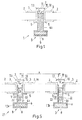
- Fig. 1 shows a schematic cross section through a sub-assembly 1 according to the invention for supporting photovoltaic modules 2.
- the photovoltaic modules 2 are framed photovoltaic modules 2 and have in the edge region of the longitudinal and transverse sides of a frame 3.
- the frame 3 may in particular consist of aluminum, which is coated with an insulating layer, for example an anodized layer.
- the subassembly 1 comprises a first retaining profile element 4a. This forms holding sections 5 for holding the photovoltaic modules 2.
- the holding sections 5 are in particular designed as abkragende webs having a support surface for the frame 3 of the photovoltaic modules 2.
- a respective photovoltaic module 2 is arranged on opposite sides of the first holding profile element 4a.
- the subassembly 1 comprises a bottom side connecting element 6 and a top side connecting element 7.
- the underside connecting element 6 is arranged in a receiving groove 8 of the first holding profile element 4a, which is formed on a lower side 9 of the first holding profile element 4a thereof.
- the receiving groove 8 may be formed here as a so-called T-slot.
- the lower side connecting element 6 is connected to the underside 9 of the first holding profile element 4a.
- a top connecting element 7, which in Fig. 1 not shown in the connected state.
- This can be connected by means of a screw, not shown, in particular a self-tapping screw, with an upper side 10 of the first holding profile element 4a.
- the upper side connecting element 7 may have a passage opening 11.
- the upper side connecting element 7 has contact surfaces 12 on a lower side for mechanically contacting an upper side of the frame 3. In the edge region of this contact surface 12 is the upper side connecting element 7 folded. The resulting edges 13 penetrate when attaching the upper side connecting member 7 on the upper side 10 of the first holding profile member 4a through the insulating layer of the frame 3, whereby they can be electrically contacted by the upper side connecting member 7.
- the first retaining profile element 4a may be formed in particular of aluminum.
- the underside connecting element 6 and the upper side connecting element 7 may be made of stainless steel, in particular as a stainless steel sheet.
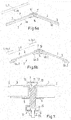
- Fig. 2 shows a schematic side view of a subassembly 1 according to the invention in a further embodiment. Shown is a first retaining profile element 4a and another retaining profile element 4b. Also shown are photovoltaic modules 2, which are arranged on the holding profile elements 4a, 4b and fastened by a top-side connecting element 7 to the holding profile elements 4a, 4b.
- the subassembly 1 comprises a bottom side connecting element 6, which is designed as an angle plate.
- the angle plate comprises two legs, which are arranged at a desired angle ⁇ angled to each other.
- the underside connecting element 6 is connected via schematically illustrated screws 14 on the lower sides 9 of the retaining profile elements 4a, 4b with these.
- a first leg of the underside connecting element 6 is connected to the underside 9 of the first retaining profile element 4a and the second leg to the underside of the further retaining profile element 4b.
- Fig. 2 is shown that the retaining profile elements 4a, 4b are arranged at an angle ⁇ to each other angled.
- the holding profile elements 4a, 4b each have beveled end-side ends 15.
- top connecting element 7 which is also connected via schematically illustrated screws 16 with tops 10 of the retaining profile elements 4a, 4b.
- the upper side connecting element 7 is formed as an angle plate, which has two with the desired angle ⁇ to each other angled legs.
- a first leg is in this case connected to the upper side 10 of the first retaining profile element 4a and the further leg to the upper side 10 of the further retaining profile element 4b.
- Fig. 3 is a schematic side view of a subassembly 1 according to the invention shown in a further embodiment.
- the retaining profile elements 4a, 4b no beveled ends 15.
- the subassembly 1 comprises an element 17 for setting the desired angle ⁇ between the retaining profile elements 4a, 4b.
- the element 17 for adjusting the angle ⁇ is formed in the form of a full profile and has two contact surfaces 18 arranged at an angle to one another, on each of which a free end 15 of a retaining profile element 4a, 4b bears.
- Fig. 3 It is shown that the underside connecting element 6 has a central passage opening, through which the element 17 protrudes.
- Fig. 4 is a side view of a subassembly 1 shown, which is formed substantially semicircular.
- holding profile elements 4a, 4b, 4c, 4d, 4e, 4f, 4g, 4h are connected to each other via lower side connecting elements and upper side connecting elements, not shown, such that a polygon is formed which approximates a semicircular shape.
- photovoltaic modules 2 see, eg Fig. 1 ), which differ from the one in Fig. 4 Part arrangement shown 1 extend toward a spaced arranged further sub-assembly, which is arranged in a direction perpendicular to the plane of the illustrated sub-assembly 1 spaced.
- the two sub-assemblies are attached to each other via the photovoltaic modules 2, whereby a stable, rigid photovoltaic system is formed.
- connecting elements 19 for connecting the free ends of the end retaining profile elements 4a, 4h with a foundation, in particular the ground 20th
- Fig. 5 shows a schematic cross section through an inventive arrangement 21 for mounting. Shown are a first and a second sub-assembly 1a, 1b of the assembly 21.
- the assembly 21 may of course comprise further sub-assemblies 1.
- the sub-assemblies 1a, 1b are in large parts corresponding to the in Fig. 1 illustrated embodiment of the subassembly 1 is formed. Therefore, the corresponding statements to Fig. 1 directed.
- a retaining profile element 4a formed as a hollow body.
- a retaining profile element 4a each have two side walls 22, wherein on each side wall 22 each have a holding portion 5 is arranged to support or support a frame 3 of a photovoltaic module 2.
- the side walls 22 are connected by three connecting webs 23 each.
- a lower connecting web 23 is part of a wall which comprises the receiving groove 8 formed as a T-groove. Between the connecting webs 23 and the side walls 22 thus cavities are formed.
- an uppermost connecting web 23 is arranged at a distance from the upper end of the side walls 22, so that at the upper end a further groove of the retaining profile element 4a is formed.
- the holding profile element 4a of the first subassembly 1a is arranged at a distance A spaced from the retaining profile element 4a of the second subassembly 1b.
- the distance A can here be measured between central axes of symmetry of the holding profile elements 4a.
- a photovoltaic module 2a is arranged between the holding profile elements 4a of the first and second sub-assembly 1 a, 1 b.
- a frame 3 arranged on a left longitudinal side of the photovoltaic module 2a rests on a holding section 5 of the holding profile element 4a of the first subassembly 1.
- a arranged on a right longitudinal side of the photovoltaic module 2a frame 3 rests on a holding portion 5 of the holding profile element 4a of the second sub-assembly 1 b.
- photovoltaic module 2a is connected via top side connecting elements 7 both to the retaining profile element 4a of the first subassembly 1a and to the retaining profile element 4a of the second subassembly 1b, then a rigid, self-supporting photovoltaic system is provided.
- Fig. 6a and Fig. 6b show schematic longitudinal sections through partial arrangements 1 according to the invention in various embodiments.
- the lengths L_4a of the holding profile elements 4a, 4b are longer than a length L_3 of the sections of the frame 3 of the photovoltaic module 2 supported by the first holding profile elements 4a, 4b.
- the lengths of the retaining profile elements 4a, 4b are shorter than a length of the sections of the frame 3 of the photovoltaic module 2 held by the first retaining profile elements 4a, 4b.
- the first retaining profile elements 4a comprises two partial profile elements 4a_1, 4a_2, each of which has end sections or end face of the photovoltaic module 2 arranged portion of the frame 3.
- the further retaining profile elements 4b comprises two partial profile elements 4b_1, 4b_2, which respectively support end sections of a section of the frame 3 arranged on a longitudinal or front side of the photovoltaic module 2.
- a sum of the length L_4a_1 of a first subelement 4a_1 of the first retaining profiled element 4a and the length L_4a_2 of a second subelement 4a_2 of the first retaining profiled element 4a is shorter than the length L_3 of the portion of the frame 3 retained by the first retaining profiled element 4a.
- the arranged on the longitudinal or front side of the photovoltaic module 2 portion of the frame 3 is not along its entire length L_3 but only in the region of the ends on the support surfaces 5 formed by the bearing surfaces.
- Fig. 7 shows a cross section through a subassembly 1 according to the invention in a further embodiment.
- Fig. 7 illustrated embodiment corresponds substantially to in Fig. 1 illustrated embodiment, so that reference may be made to the corresponding statements to claim 1.
- the underside connecting element 6 is arranged on the underside 9 of the first retaining profiled element 4a outside the receiving groove 8 of the first retaining profiled element 4a.
- the receiving groove 8 is a part of a hammer head screw 24, in particular the head part arranged.
- the lower side connecting member 6 may have a through hole for the hammer head screw 24.
- a nut 25 which serves to fasten the underside connecting element 6 on the underside 9, is screwed onto the threaded portion of the hammer head screw 24.
Landscapes
- Engineering & Computer Science (AREA)
- Physics & Mathematics (AREA)
- Life Sciences & Earth Sciences (AREA)
- Sustainable Development (AREA)
- Sustainable Energy (AREA)
- Thermal Sciences (AREA)
- Chemical & Material Sciences (AREA)
- Combustion & Propulsion (AREA)
- Mechanical Engineering (AREA)
- General Engineering & Computer Science (AREA)
- Photovoltaic Devices (AREA)
- Optical Couplings Of Light Guides (AREA)
Applications Claiming Priority (1)
| Application Number | Priority Date | Filing Date | Title |
|---|---|---|---|
| DE102015206062.4A DE102015206062A1 (de) | 2015-04-02 | 2015-04-02 | Teilanordnung und Anordnung zur Halterung mindestens eines Photovoltaikmoduls sowie Verfahren zur Herstellung einer Teilanordnung |
Publications (1)
| Publication Number | Publication Date |
|---|---|
| EP3076103A1 true EP3076103A1 (fr) | 2016-10-05 |
Family
ID=55650281
Family Applications (1)
| Application Number | Title | Priority Date | Filing Date |
|---|---|---|---|
| EP16163105.6A Withdrawn EP3076103A1 (fr) | 2015-04-02 | 2016-03-31 | Sous-ensemble et ensemble destines a maintenir au moins un module photovoltaïque et procede de fabrication d'un sous-ensemble |
Country Status (3)
| Country | Link |
|---|---|
| EP (1) | EP3076103A1 (fr) |
| CN (1) | CN106059457B (fr) |
| DE (1) | DE102015206062A1 (fr) |
Cited By (2)
| Publication number | Priority date | Publication date | Assignee | Title |
|---|---|---|---|---|
| WO2021089679A1 (fr) * | 2019-11-05 | 2021-05-14 | Goldbeck Solar Gmbh | Ensemble solaire pour la production d'énergie solaire |
| EP3972125A3 (fr) * | 2020-09-15 | 2022-07-06 | Premium Mounting Technologies GmbH & Co. KG | Installation photovoltaïque pour produire de l'énergie solaire |
Families Citing this family (1)
| Publication number | Priority date | Publication date | Assignee | Title |
|---|---|---|---|---|
| DE102020124058A1 (de) | 2020-09-15 | 2022-03-17 | Premium Mounting Technologies GmbH & Co. KG | Photovoltaik-Anlage zum Erzeugen von Solarstrom |
Citations (16)
| Publication number | Priority date | Publication date | Assignee | Title |
|---|---|---|---|---|
| DE10047400A1 (de) * | 2000-09-26 | 2002-04-18 | Hne Elektronik Gmbh & Co Satel | Photovoltaische Solarvorrichtung |
| US20050257453A1 (en) * | 2004-05-18 | 2005-11-24 | Barry Cinnamon | Mounting system for a solar panel |
| DE202009014723U1 (de) | 2009-10-31 | 2010-02-25 | Tropberger, Dieter | Eine in Stahl gefertigte Solar-Modul-Trägerkonstruktion für serienproduzierte Photovoltaikmodule |
| US20100096073A1 (en) | 2008-09-16 | 2010-04-22 | Adriani Paul M | Compression or arched mounting of solar panels |
| DE102010010676A1 (de) * | 2010-03-08 | 2011-09-08 | Gudrun Arau | Überdachung, insbesondere Dachabdeckung |
| FR2957405A1 (fr) * | 2010-03-10 | 2011-09-16 | Altus Energy | Dispositif d'installation de panneaux solaires |
| DE202010017294U1 (de) * | 2009-09-15 | 2011-12-22 | Rem Gmbh | Anordnung, Unterkonstruktion und Photovoltaikanlage |
| DE102011016262A1 (de) * | 2011-04-06 | 2012-10-11 | Wolfgang Gerdemann | Photovoltaik-Indach |
| DE102011007521A1 (de) | 2011-04-15 | 2012-10-18 | Inventux Technologies Ag | Unterkonstruktion für eine Solarmodul-Freilandanordnung |
| WO2012148261A2 (fr) * | 2011-04-29 | 2012-11-01 | Peter Joost Wieriks | Éléments de raccordement de profilés pour des systèmes de montage de panneaux solaires |
| US20130175231A1 (en) * | 2011-07-12 | 2013-07-11 | Lumos Lsx, Llc | Photovoltaic panel carrier device |
| EP2642218A1 (fr) | 2012-03-23 | 2013-09-25 | Brandoni Solare S.p.A. | Appareil modulaire permettant une intégration architecturale de modules solaires sans cadre |
| EP2648231A2 (fr) * | 2012-04-02 | 2013-10-09 | Creotecc GmbH | Système de montage pour la pose de modules photovoltaïques selon une orientation est-ouest |
| WO2014029499A1 (fr) * | 2012-08-23 | 2014-02-27 | Adensis Gmbh | Générateur photovoltaïque en forme de toit à pignon posé sur des éléments de support au sol |
| JP2014037685A (ja) | 2012-08-13 | 2014-02-27 | Nisshin Steel Co Ltd | 太陽光発電モジュールの金具並びに太陽光発電モジュールの建築物への設置方法 |
| EP2725309A1 (fr) * | 2012-10-23 | 2014-04-30 | Terom S.P.A. | Structure pour l'installation de panneaux photovoltaïques sur des toits ou des façades de bâtiments, avec refroidissement d'air et récupération éventuelle de l'énergie thermique |
Family Cites Families (8)
| Publication number | Priority date | Publication date | Assignee | Title |
|---|---|---|---|---|
| US8273980B2 (en) * | 2005-09-30 | 2012-09-25 | General Electric Company | Photovoltaic roof ridge cap and installation method |
| CN101599510B (zh) * | 2009-07-01 | 2011-08-17 | 天津市津能电池科技有限公司 | 人字形斜面屋顶太阳电池方阵 |
| CN201635270U (zh) * | 2010-02-20 | 2010-11-17 | 欧贝黎新能源科技股份有限公司 | 太阳能斜屋顶安装铝材结构 |
| DE102010023259A1 (de) * | 2010-06-09 | 2011-11-03 | Gudrun Arau | Überdachung, insbesondere Dachabdeckung |
| CN201804876U (zh) * | 2010-07-28 | 2011-04-20 | 福建钧石能源有限公司 | 太阳能电池板安装支架 |
| DE102011010148A1 (de) * | 2011-02-02 | 2012-08-02 | Franz Öller | Montageklammer zur Befestigung von gerahmten Photovoltaikmodulen auf Montageschienen, die eine abgedichtete, stromleitende Verbindung zwischen den Modulen herstellt |
| DE102012009486A1 (de) * | 2012-05-09 | 2013-11-14 | K2 Systems Gmbh | Solarmodulhalter |
| CN204179996U (zh) * | 2014-09-24 | 2015-02-25 | 浙江贝立德能源科技有限公司 | 一种组成屋顶结构的光伏并网系统结构 |
-
2015
- 2015-04-02 DE DE102015206062.4A patent/DE102015206062A1/de not_active Ceased
-
2016
- 2016-03-31 EP EP16163105.6A patent/EP3076103A1/fr not_active Withdrawn
- 2016-04-01 CN CN201610383154.2A patent/CN106059457B/zh not_active Expired - Fee Related
Patent Citations (17)
| Publication number | Priority date | Publication date | Assignee | Title |
|---|---|---|---|---|
| DE10047400A1 (de) * | 2000-09-26 | 2002-04-18 | Hne Elektronik Gmbh & Co Satel | Photovoltaische Solarvorrichtung |
| US20050257453A1 (en) * | 2004-05-18 | 2005-11-24 | Barry Cinnamon | Mounting system for a solar panel |
| US20100096073A1 (en) | 2008-09-16 | 2010-04-22 | Adriani Paul M | Compression or arched mounting of solar panels |
| DE202010017294U1 (de) * | 2009-09-15 | 2011-12-22 | Rem Gmbh | Anordnung, Unterkonstruktion und Photovoltaikanlage |
| DE202009014723U1 (de) | 2009-10-31 | 2010-02-25 | Tropberger, Dieter | Eine in Stahl gefertigte Solar-Modul-Trägerkonstruktion für serienproduzierte Photovoltaikmodule |
| DE102010010676A1 (de) * | 2010-03-08 | 2011-09-08 | Gudrun Arau | Überdachung, insbesondere Dachabdeckung |
| FR2957405A1 (fr) * | 2010-03-10 | 2011-09-16 | Altus Energy | Dispositif d'installation de panneaux solaires |
| DE102011016262A1 (de) * | 2011-04-06 | 2012-10-11 | Wolfgang Gerdemann | Photovoltaik-Indach |
| DE102011007521A1 (de) | 2011-04-15 | 2012-10-18 | Inventux Technologies Ag | Unterkonstruktion für eine Solarmodul-Freilandanordnung |
| WO2012148261A2 (fr) * | 2011-04-29 | 2012-11-01 | Peter Joost Wieriks | Éléments de raccordement de profilés pour des systèmes de montage de panneaux solaires |
| US20130175231A1 (en) * | 2011-07-12 | 2013-07-11 | Lumos Lsx, Llc | Photovoltaic panel carrier device |
| EP2642218A1 (fr) | 2012-03-23 | 2013-09-25 | Brandoni Solare S.p.A. | Appareil modulaire permettant une intégration architecturale de modules solaires sans cadre |
| EP2648231A2 (fr) * | 2012-04-02 | 2013-10-09 | Creotecc GmbH | Système de montage pour la pose de modules photovoltaïques selon une orientation est-ouest |
| JP2014037685A (ja) | 2012-08-13 | 2014-02-27 | Nisshin Steel Co Ltd | 太陽光発電モジュールの金具並びに太陽光発電モジュールの建築物への設置方法 |
| WO2014029499A1 (fr) * | 2012-08-23 | 2014-02-27 | Adensis Gmbh | Générateur photovoltaïque en forme de toit à pignon posé sur des éléments de support au sol |
| DE102012016807A1 (de) * | 2012-08-23 | 2014-02-27 | Adensis Gmbh | Giebeldachförmiger PV-Generator auf Bodenstützelementen |
| EP2725309A1 (fr) * | 2012-10-23 | 2014-04-30 | Terom S.P.A. | Structure pour l'installation de panneaux photovoltaïques sur des toits ou des façades de bâtiments, avec refroidissement d'air et récupération éventuelle de l'énergie thermique |
Cited By (3)
| Publication number | Priority date | Publication date | Assignee | Title |
|---|---|---|---|---|
| WO2021089679A1 (fr) * | 2019-11-05 | 2021-05-14 | Goldbeck Solar Gmbh | Ensemble solaire pour la production d'énergie solaire |
| EP3972125A3 (fr) * | 2020-09-15 | 2022-07-06 | Premium Mounting Technologies GmbH & Co. KG | Installation photovoltaïque pour produire de l'énergie solaire |
| EP4184789A1 (fr) | 2020-09-15 | 2023-05-24 | Premium Mounting Technologies GmbH & Co. KG | Installation photovoltaïque pour la production d'énergie solaire |
Also Published As
| Publication number | Publication date |
|---|---|
| CN106059457A (zh) | 2016-10-26 |
| DE102015206062A1 (de) | 2016-10-06 |
| CN106059457B (zh) | 2019-09-10 |
Similar Documents
| Publication | Publication Date | Title |
|---|---|---|
| EP3004752B1 (fr) | Dispositif de fixation pour modules photovoltaïques sur des toits avec une tôle trapézoïdale | |
| EP3256795B1 (fr) | Dispositif de serrage et procédé pour le montage d'un module solaire | |
| EP2385324A2 (fr) | Dispositif destiné à l'élévation de modules solaires | |
| WO2008009530A2 (fr) | Structure porteuse pour une installation solaire et installation solaire munie d'une telle structure porteuse | |
| WO2016198305A1 (fr) | Étrier de montage pour module photovoltaïque ainsi que système photovoltaïque | |
| EP2003406A2 (fr) | Agencement de support pour une installation solaire, installation solaire dotée de plusieurs modules solaires et module solaire correspondant | |
| DE202009011708U1 (de) | Befestigungselement | |
| EP3803228B1 (fr) | Système de montage pour monter des modules photovoltaïques sur des toits, comprenant des composants de système de montage reliés par des moyens d'assemblage par encliquetage | |
| DE202005012993U1 (de) | Traganordnung für Solaranlagen, Modulträger für eine solche Traganordnung und Solaranlage mit Modulträgern | |
| DE202005003224U1 (de) | Montagesystem mit einer mindestens eine hinterschnittene Profilnut aufweisenden Profilleiste | |
| EP3076103A1 (fr) | Sous-ensemble et ensemble destines a maintenir au moins un module photovoltaïque et procede de fabrication d'un sous-ensemble | |
| DE202008002297U1 (de) | Traganordnung für eine Solaranlage und zugehöriger Querträger | |
| CH717416B1 (de) | Tragkonstruktion für vertikal angeordnete Photovoltaik-Module. | |
| WO2014075746A1 (fr) | Système de montage pour modules solaires | |
| EP4184789A1 (fr) | Installation photovoltaïque pour la production d'énergie solaire | |
| DE19831453A1 (de) | Einstellbare Befestigung für Gegenstände, insbesondere Glasplatten auf einer Unterkonstruktion | |
| EP2775231B1 (fr) | Etrier de montage | |
| DE202024100099U1 (de) | Befestigungsvorrichtung | |
| DE9201273U1 (de) | Modulbefestigung | |
| DE102012206166A1 (de) | Klemmvorrichtung mit einer Klemmbacke, welche einen Grundkörper kappenartig umschließt | |
| DE102009017164A1 (de) | Haltevorrichtung | |
| EP1406021B1 (fr) | Dispositif à fixation | |
| DE112013006791B4 (de) | Haltevorrichtung | |
| AT528501B1 (de) | Vorrichtung zur Montage von Solarpanels | |
| EP2775232A2 (fr) | Dispositif de fixation pour la fixation d'une sous-structure pour la réception de modules et capteurs solaires |
Legal Events
| Date | Code | Title | Description |
|---|---|---|---|
| PUAI | Public reference made under article 153(3) epc to a published international application that has entered the european phase |
Free format text: ORIGINAL CODE: 0009012 |
|
| AK | Designated contracting states |
Kind code of ref document: A1 Designated state(s): AL AT BE BG CH CY CZ DE DK EE ES FI FR GB GR HR HU IE IS IT LI LT LU LV MC MK MT NL NO PL PT RO RS SE SI SK SM TR |
|
| AX | Request for extension of the european patent |
Extension state: BA ME |
|
| 17P | Request for examination filed |
Effective date: 20170405 |
|
| RBV | Designated contracting states (corrected) |
Designated state(s): AL AT BE BG CH CY CZ DE DK EE ES FI FR GB GR HR HU IE IS IT LI LT LU LV MC MK MT NL NO PL PT RO RS SE SI SK SM TR |
|
| 17Q | First examination report despatched |
Effective date: 20180111 |
|
| STAA | Information on the status of an ep patent application or granted ep patent |
Free format text: STATUS: THE APPLICATION IS DEEMED TO BE WITHDRAWN |
|
| 18D | Application deemed to be withdrawn |
Effective date: 20180523 |