EP3076113B1 - Kühlschrank - Google Patents
Kühlschrank Download PDFInfo
- Publication number
- EP3076113B1 EP3076113B1 EP14865585.5A EP14865585A EP3076113B1 EP 3076113 B1 EP3076113 B1 EP 3076113B1 EP 14865585 A EP14865585 A EP 14865585A EP 3076113 B1 EP3076113 B1 EP 3076113B1
- Authority
- EP
- European Patent Office
- Prior art keywords
- bracket
- coupled
- refrigerator
- main body
- coupling
- Prior art date
- Legal status (The legal status is an assumption and is not a legal conclusion. Google has not performed a legal analysis and makes no representation as to the accuracy of the status listed.)
- Not-in-force
Links
Images






Classifications
-
- F—MECHANICAL ENGINEERING; LIGHTING; HEATING; WEAPONS; BLASTING
- F25—REFRIGERATION OR COOLING; COMBINED HEATING AND REFRIGERATION SYSTEMS; HEAT PUMP SYSTEMS; MANUFACTURE OR STORAGE OF ICE; LIQUEFACTION SOLIDIFICATION OF GASES
- F25D—REFRIGERATORS; COLD ROOMS; ICE-BOXES; COOLING OR FREEZING APPARATUS NOT OTHERWISE PROVIDED FOR
- F25D23/00—General constructional features
- F25D23/02—Doors; Covers
- F25D23/028—Details
-
- E—FIXED CONSTRUCTIONS
- E05—LOCKS; KEYS; WINDOW OR DOOR FITTINGS; SAFES
- E05D—HINGES OR SUSPENSION DEVICES FOR DOORS, WINDOWS OR WINGS
- E05D5/00—Construction of single parts, e.g. the parts for attachment
- E05D5/02—Parts for attachment, e.g. flaps
- E05D5/04—Flat flaps
-
- E—FIXED CONSTRUCTIONS
- E05—LOCKS; KEYS; WINDOW OR DOOR FITTINGS; SAFES
- E05D—HINGES OR SUSPENSION DEVICES FOR DOORS, WINDOWS OR WINGS
- E05D7/00—Hinges or pivots of special construction
- E05D7/08—Hinges or pivots of special construction for use in suspensions comprising two spigots placed at opposite edges of the wing, especially at the top and the bottom, e.g. trunnions
- E05D7/081—Hinges or pivots of special construction for use in suspensions comprising two spigots placed at opposite edges of the wing, especially at the top and the bottom, e.g. trunnions the pivot axis of the wing being situated near one edge of the wing, especially at the top and bottom, e.g. trunnions
-
- E—FIXED CONSTRUCTIONS
- E05—LOCKS; KEYS; WINDOW OR DOOR FITTINGS; SAFES
- E05D—HINGES OR SUSPENSION DEVICES FOR DOORS, WINDOWS OR WINGS
- E05D7/00—Hinges or pivots of special construction
- E05D7/12—Hinges or pivots of special construction to allow easy detachment of the hinge from the wing or the frame
-
- E—FIXED CONSTRUCTIONS
- E05—LOCKS; KEYS; WINDOW OR DOOR FITTINGS; SAFES
- E05D—HINGES OR SUSPENSION DEVICES FOR DOORS, WINDOWS OR WINGS
- E05D7/00—Hinges or pivots of special construction
- E05D7/12—Hinges or pivots of special construction to allow easy detachment of the hinge from the wing or the frame
- E05D2007/128—Hinges or pivots of special construction to allow easy detachment of the hinge from the wing or the frame in a radial direction
-
- E—FIXED CONSTRUCTIONS
- E05—LOCKS; KEYS; WINDOW OR DOOR FITTINGS; SAFES
- E05Y—INDEXING SCHEME ASSOCIATED WITH SUBCLASSES E05D AND E05F, RELATING TO CONSTRUCTION ELEMENTS, ELECTRIC CONTROL, POWER SUPPLY, POWER SIGNAL OR TRANSMISSION, USER INTERFACES, MOUNTING OR COUPLING, DETAILS, ACCESSORIES, AUXILIARY OPERATIONS NOT OTHERWISE PROVIDED FOR, APPLICATION THEREOF
- E05Y2900/00—Application of doors, windows, wings or fittings thereof
- E05Y2900/30—Application of doors, windows, wings or fittings thereof for domestic appliances
- E05Y2900/31—Application of doors, windows, wings or fittings thereof for domestic appliances for refrigerators
-
- F—MECHANICAL ENGINEERING; LIGHTING; HEATING; WEAPONS; BLASTING
- F25—REFRIGERATION OR COOLING; COMBINED HEATING AND REFRIGERATION SYSTEMS; HEAT PUMP SYSTEMS; MANUFACTURE OR STORAGE OF ICE; LIQUEFACTION SOLIDIFICATION OF GASES
- F25D—REFRIGERATORS; COLD ROOMS; ICE-BOXES; COOLING OR FREEZING APPARATUS NOT OTHERWISE PROVIDED FOR
- F25D2323/00—General constructional features not provided for in other groups of this subclass
- F25D2323/02—Details of doors or covers not otherwise covered
- F25D2323/024—Door hinges
Definitions
- the present invention relates to a refrigerator, and more particularly, to a refrigerator that has an improved structure to facilitate assembling a door and a main body which are separable from each other.
- a refrigerator is an apparatus that includes a main body that forms an exterior appearance of the refrigerator, a storage compartment that is provided inside the main body in such a manner that a front surface of the storage compartment is open, and a cool air supplying apparatus that supplies the storage compartment with cool air, and keeps food fresh.
- the open front surface of the storage compartment of the refrigerator is normally closed by a door in order to maintain the temperature of the storage compartment.
- the door is hinge-coupled to the main body and mounted to the main body in a selectively rotatable manner.
- a hinge device provided in each of upper and lower portions of the refrigerator should be disassembled.
- a bolt provided in the bottom surface of the main body should be removed so as to fix the hinge device so that discomfort such that the refrigerator should be laid on its side is created.
- the present invention is directed to providing a refrigerator in which a door and a main body can be separated in a state in which the refrigerator stands upright, thereby having an improved structure to improve the ease of installation of the refrigerator.
- the present invention is also directed to providing a refrigerator which has an improved structure to improve the durability of a separable hinge bracket.
- a refrigerator including: a main body that forms an exterior appearance; a storage compartment that is provided inside the main body; a door that is rotatably coupled to the main body so as to open and close an open front surface of the storage compartment; and a hinge bracket that connects the main body and the door, wherein the hinge bracket includes a first bracket that is coupled to the main body and a second bracket that is coupled to the door and detachably coupled to the first bracket;
- the second bracket may be detachably coupled to the first bracket in forward and backward directions.
- the plurality of legs may further include a second leg that faces the first leg and in which a guide unit for guiding movement of the second bracket is formed.
- the guide unit may be recessed on an inner wall of the second leg.
- a second coupling hole corresponding to the first coupling hole may be formed in one surface of the second bracket facing the first leg, and the first bracket and the second bracket may be coupled to each other by the coupling member passing through the first coupling hole and the second coupling hole.
- the hinge bracket may further include a fixing unit that fixes the second bracket to the first bracket so that the first coupling hole and the second coupling hole are positioned on a straight line in a coupling direction of the coupling member.
- the fixing guide may have a shape that extends from the body toward a rear side of the first bracket and is bent.
- the fixing guide may have a pin shape that protrudes from the body toward a lower side of the first bracket.
- the fixing guide may include a head, and a neck that has a smaller width than that of the head so as to be fastened to the fixing groove, and connects the head and the body.
- a hinge bracket installed in a lower portion of a refrigerator may be constituted of a first bracket coupled to a main body and a second bracket coupled to a door which are separable from each other, and therefore the door and the main body can be easily separated in a state in which the refrigerator stands upright, thereby improving the ease of installation of the refrigerator.
- one or more connection members installed in the first bracket and one or more coupling members passing through the first bracket and the second bracket may be used in order to couple the first bracket and the second bracket which are separable from each other, and therefore it is possible to improve the durability of the hinge bracket constituted of the first bracket and the second bracket so that the first bracket and the second bracket which are installed in the lower portion of the refrigerator may stand the load of the door and the main body.
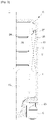
- FIG. 1 is a perspective view showing an exterior appearance of a refrigerator in accordance with one embodiment of the present invention
- FIG. 2 is a cross-sectional view showing a refrigerator in accordance with one embodiment of the present invention
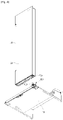
- FIG. 3 is a perspective view showing a state in which a door of a refrigerator in accordance with one embodiment of the present invention is opened
- FIG. 4 is a perspective view showing a coupling relationship between a door and a main body of a refrigerator in accordance with an illustrative example.
- a refrigerator 1 includes a main body 10 that forms an exterior appearance, a storage compartment 20 that is provided in the main body 10 to have an open front surface, a door 30 that opens and closes the storage compartment 20, and a hinge module 40 that includes an upper hinge 41 and a lower hinge 43 to allow the door 30 to be rotatably coupled to the main body 10.
- the upper hinge 41 and the lower hinge 43 are fixed on both upper and lower end portions of the main body 10 and provide a rotation center axis for opening and closing the door 30.
- a hinge pin (not shown) of the upper hinge 41 is inserted into a pin insertion hole (not shown) formed in a top corner portion of the door 30 and acts as a rotary shaft at the time of opening and closing operations of the door 30.
- a hinge pin 43a of the lower hinge 43 is inserted into a pin insertion hole 43b formed in a bottom corner portion of the door 30 and acts as a rotary shaft at the time of opening and closing operations of the door 30 together with the hinge pin of the upper hinge 41.
- the hinge pin 43a of the lower hinge 43 passes through a pin coupling hole 44 formed in a second bracket 120 (see FIG. 5 ) coupled to the lower end portion of the door 30, and coupled to the pin insertion hole 43b formed in the bottom corner portion of the door 30. Accordingly, a user may open and close the storage compartment 20 using a door handle 50 provided in a front surface of the door 30.
- the main body 10 includes an inner case 11 that forms the storage compartment 20, an outer case 13 that forms the exterior appearance, and a cool air supplying apparatus that supplies the storage compartment 20 with cool air.
- the cool air supplying apparatus includes a compressor C, a condenser (not shown), an expansion valve (not shown), an evaporator 26, a blower fan 27, and the like, and a heat insulating material 15 is foamed between the inner case 11 and the outer case 13 of the main body 10 to prevent cool air of the storage compartment 20 from being discharged.
- a machine room 23 is provided at a lower rear portion of the body 10 such that the compressor C for compressing a refrigerant and the condenser for condensing the compressed refrigerant are installed therein.
- a refrigerator compartment 21 and a freezer compartment 22 are respectively opened and closed by a refrigerator door 31 and a freezer door 33 which are rotatably coupled to the body 10, and a plurality of door guards 35 to accommodate food are provided at rear surfaces of the refrigerator door 21 and the freezer door 33.
- a plurality of shelves 24 are provided in the storage compartment 20 to divide the storage compartment 20 into a plurality of sections, and articles such as food may be loaded on the shelves 24.
- a plurality of storage boxes 25 are provided to be taken in and out of the storage compartment 20 in a slidable manner.
- a foaming space S is provided between the inner case 11 that forms the storage compartment 20 and the outer case 13 coupled to the outer side of the inner case 11 to form the exterior appearance, and the heat insulating material 15 is filled inside the foaming space S.
- a vacuum insulation panel (VIP) (not shown) may be filled together with the heat insulating material 15.
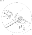
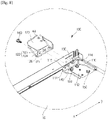
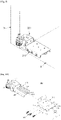
- FIG. 5 is an exploded perspective view showing a hinge bracket in a refrigeratoraccording to an illustrative example that does not form part of the claimed invention .
- a second coupling member 160 may be used with the same meaning as a coupling member.
- at least one of the upper hinge 41 and the lower hinge 43 may have a type of a hinge bracket 100 in accordance with the illustrative example .
- the hinge bracket 100 in accordance with the illustrative example may be in a more preferable form at the lower hinge 43. Therefore, hereinafter, the hinge bracket 100 that is used at the lower hinge 43 will be the focus of the description.
- the hinge bracket 100 connecting the door 30 and the main body 10 may include a first bracket 110 and a second bracket 120.
- the first bracket 110 is coupled to a bottom surface of the main body 10.
- One or more insertion holes 113 are formed in a bottom surface 112 of the first bracket 110 facing the bottom surface of the main body 10, and the first bracket 110 is fixed to the bottom surface of the main body 10 by one or more first coupling members 150 passing through the one or more insertion holes 113.
- One or more fastening holes 114 and one or more first fixing holes 115 may be formed in a front surface 111 of the first bracket 110 toward the front, and a description thereof will be made later.
- the second bracket 120 may be coupled to a bottom surface of the door 30, and detachably coupled to the front side of the first bracket 110.
- One or more connection members 130 connecting the first bracket 110 and the second bracket 120 may be installed in the first bracket 110.
- the one or more connection members 130 are coupled to the one or more fastening holes 114 which are formed in the front surface 111 of the first bracket 110 so as to correspond to the one or more connection members 130.
- the one or more connection members 130 may include a body 131 and a head 132.
- the body 131 is coupled to the one or more fastening holes 114 so as to face the rear of the first bracket 110, and the head 132 extends from the body 131 so as to face the front of the first bracket 110.
- the one or more connection members 130 are coupled to the one or more fastening holes 114 in such a manner that the head 132 protrudes toward the front of the first bracket 110.
- the head 132 may protrude toward the outside of the body 131 so as to have a larger diameter than the diameter of the body 131.
- connection members 130 may be formed integrally with the first bracket 110 in such a manner that the head 132 protrudes toward the front of the first bracket 110.
- One or more stoppers 140 may be provided in the first bracket 110.
- the one or more stoppers 140 may be provided behind the one or more fastening holes 114 so as to support the one or more connection members 130 passing through the one or more fastening holes 114.
- the one or more stoppers 140 may be coupled to a recessed portion (not shown) formed on the bottom surface 112 of the first bracket 110, and have a shape protruding toward the lower side of the main body 10.
- the one or more stoppers 140 may face one end of the body 131 of the one or more connection members 130 passing through the one or more fastening holes 114.
- connection member through-holes 122 corresponding to the one or more connection members 130 may be formed in a rear surface 121 of the second bracket 120 facing the front surface 111 of the first bracket 110 in such a manner that the second bracket 120 is detachably coupled to the one or more connection members 130.
- connection member through-holes 122 may include a fastening unit 123 and a locking unit 124.
- the fastening unit 123 and the locking unit 124 may have different diameters from each other. Specifically, the fastening unit 123 may have a larger diameter than that of the head 132 so that the head 132 may be coupled to or separated from the fastening unit 123, and the locking unit 124 may have a smaller diameter than that of the head 132 so as to prevent the head 132 from being separated from the one or more connection member through-holes 122.
- the fastening unit 123 and the locking unit 124 may be connected to each other so that the one or more connection members 130 can be moved between the fastening unit 123 and the locking unit 124.
- the body 131 is coupled to the locking unit 124 so that the one or more connection members 130 are fixed to the one or more connection member through-holes 122.
- the fastening unit 123 and the locking unit 124 may have different shapes from each other.
- the fastening unit 123 may have a shape corresponding to the head 132 so that the head 132 can pass through the fastening unit 123 toward the front of the second bracket 120
- the locking unit 124 may have a shape corresponding to the body 131 so as to grasp and fix the outer surface of the body 131.
- the fastening unit 123 has a larger width than that of the locking unit 124 coupled to the body 131 so that the head 132 having a larger width than that of the body 131 can pass through the fastening unit 123.
- One or more second fixing holes 126 corresponding to the one or more first fixing holes 115 provided in the front surface 111 of the first bracket 110 may be formed in the rear surface 121 of the second bracket 120 facing the one or more fastening holes 114.
- the second bracket 120 may be coupled to the front surface 111 of the first bracket 110 so as to face the rear of the first bracket 110 by the second coupling member 160 passing through the one or more second fixing holes 126 and the one or more first fixing holes 115 so that the binding force between the first bracket 110 and the second bracket 120 caused by the one or more connection members 130 may be complemented.
- the first coupling member 150 and the second coupling member 160 may include bolts.
- FIG. 6 is a perspective view showing a state in which a coupling member of the hinge bracket according to an illustrative example that does not form part of the claimed invention is separated in a refrigerator
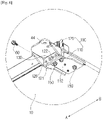
- FIG. 7 is a perspective view showing a state in which a second bracket of the hinge bracket according to an illustrative example that does not form part of the claimed invention is separated from a first bracket in a refrigerator
- FIG. 8 is a perspective view showing a state in which the second bracket of the hinge bracket according to an illustrative example that does not form part of the claimed invention has been separated from the first bracket in a refrigerator.
- Unillustrated reference numerals refer to Figs. 1 to 5 .
- a process in which the second bracket 120 is coupled to the first bracket 110 is as follows.
- the second bracket 120 is disposed in front of the first bracket 110 so that the one or more connection member through-holes 122 may face the one or more connection members 130.
- the second bracket 120 is made to approach the front surface 111 of the first bracket 110 so that the head 132 of the one or more connection members 130 can pass through the fastening unit 123 of the one or more connection member through-holes 122.
- the second bracket 120 is slid in a first direction A.
- the second bracket 120 is slid in the first direction A, the head 132 is positioned in front of the locking unit 124, and one end of the body 131 extending from the head 132 is coupled to the locking unit 124 so that the second bracket 120 is coupled to the first bracket 110.
- the second coupling member 160 sequentially passing through the second fixing hole 126 and the first fixing hole 115 is coupled to the second bracket 120 and the first bracket 110.
- a process in which the second bracket 120 is separated from the first bracket 110 is as follows.
- the second coupling member 160 that has sequentially passed through the second fixing hole 126 and the first fixing hole 115 toward the rear of the first bracket 110 so as to connect the first bracket 110 and the second bracket 120 is removed.
- the head 132 is positioned in front of the fastening unit 123 and the body 131 is spaced apart from the locking unit 124.
- the one or more connection members 130 are positioned on a straight line with the fastening unit 123.
- the first direction A and the second direction B are opposite to each other.
- FIG. 9 is a perspective view showing a hinge bracket in accordance with a first embodiment in a refrigerator in accordance with one embodiment of the present invention
- FIG. 10 is an exploded perspective view showing the hinge bracket in accordance with the first embodiment in a refrigerator in accordance with one embodiment of the present invention.
- unillustrated reference numerals refer to FIGS. 1 to 4 .
- at least one of the upper hinge 41 and the lower hinge 43 may have a form of a hinge bracket 200 in accordance with the first embodiment.
- the door 30 should be separated from the main body 10.
- the hinge bracket 200 in accordance with the first embodiment of the present invention may be in a more preferable form at the lower hinge 43. Therefore, hereinafter, the hinge bracket 200 that is used at the lower hinge 43 will be the focus of the description.
- the hinge bracket 200 connecting the door 30 and the main body 10 may include a first bracket 210 and a second bracket 220.
- the first bracket 210 may be coupled to the main body 10. Specifically, the first bracket 210 may be coupled to the bottom surface of the main body 10.
- the first bracket 210 may include a body 211.
- the body 211 may be disposed so as to face the main body 10, that is, the bottom surface of the main body 10.
- the body 211 may be fixedly coupled to the main body 10.
- the first bracket 210 may further include a plurality of legs 212 and 213.
- the plurality of legs 212 and 213 may form an opening 214 (see FIG. 11A ) that is open toward the front of the first bracket 210 together with the body 211 so that the second bracket 220 can be inserted into the plurality of legs 212 and 213.
- the plurality of legs 212 and 213 may include a first leg 212 and a second leg 213.
- the first leg 212 may be connected to the body 211 in such a manner to face outside of the main body 10.
- the second leg 213 may be connected to the body 211 in such a manner to face inside of the main body 10.
- a first coupling hole 215 to which a coupling member 230 is coupled may be formed in the first leg 212.
- one or more first coupling holes 215 may be formed in the first leg 212.
- the second leg 213 may face the first leg 212.
- a guide unit 216 for guiding the movement of the second bracket 220 may be formed in the second leg 213.
- the guide unit 216 may be recessed on the inner wall of the second leg 213.
- the guide unit 216 may have a cross-section of " ⁇ "-shape that is open toward the inside of the first bracket 210 (see FIG. 10 ).
- the guide unit 216 may serve to fix the positions of the first bracket 210 and the second bracket 220 so that the first bracket 210 and the second bracket 220 are connectable with each other by the coupling member 230 together with a fixing unit 240.
- the second bracket 220 may be coupled to the door 30. Specifically, the second bracket 220 may be coupled to the bottom surface of the door 30.
- the second bracket 220 may be detachably coupled to the first bracket 210.
- the second bracket 220 may be detachably coupled to the first bracket 210 in forward and backward directions.
- the second bracket 220 may be slidably coupled to the first bracket 210.
- the second bracket 220 may be slidably coupled to the inner side of the first bracket 210.
- the second bracket 220 may be inserted into the opening 214 of the first bracket 210 and moved toward the rear of the main body 10 along the guide unit 216.
- the fixing unit 240 may serve as a stopper that limits the movement of the second bracket 220 facing the rear of the main body 10.
- the second bracket 220 may include a first portion 221 and a second portion 222.
- the first portion 221 may face the door 30.
- An adjustment portion 223 for adjusting the height or level of the refrigerator 1 may be installed in the first portion 221.
- the height or level of the refrigerator 1 may be adjusted by rotating the adjustment portion 223. As an example, when the adjustment portion 223 is rotated in the clockwise direction, the height of the refrigerator 1 may be increased. When the adjustment portion 223 is rotated in the counterclockwise direction, the height of the refrigerator 1 may be reduced.
- a method of adjusting the height or level of the refrigerator 1 is not limited thereto, and may be variously modified.
- the adjustment portion 223 may connect the second bracket 220 and the door 30.
- the second portion 222 may extend from the first portion 221 toward the main body 10.
- the second portion 222 may be coupled to the first bracket 210. Specifically, the second portion 222 may be inserted into the opening 214 of the first bracket 210 and moved toward the rear of the main body 10 along the guide unit 216.
- the first portion 221 of the second bracket 220 may be positioned in front of the first bracket 210, and the second portion 222 of the second bracket 220 may be positioned inside the first bracket 210.
- a second coupling hole 225 may be formed in one surface of the second bracket 220.
- the second coupling hole 225 corresponding to a first coupling hole 215 may be formed in the one surface of the second bracket 220 facing the first leg 212.
- the second coupling hole 225 may be formed in one surface of the second portion 222 facing the first leg 212.
- the shape and number of the second coupling holes 225 may correspond to the shape and number of the first coupling holes 215.
- the shape and number of the first coupling holes 215 and the second coupling holes 225 may correspond to the shape and number of the coupling members 230.
- the hinge bracket 200 may further include the coupling member 230 for allowing the first bracket 210 and the second bracket 220 to be coupled to each other.
- the coupling member 230 may allow the second bracket 220 to be coupled to one or more surfaces of the first bracket 210.
- the coupling member 230 may allow the one surface of the second bracket 220 facing the first leg 212 to be coupled to the first leg 212.
- the first bracket 210 and the second bracket 220 may be coupled to each other by the coupling member 230 passing through the first coupling hole 215 and the second coupling hole 225.
- the one surface of the second bracket 220 may be coupled to the first leg 212 of the first bracket 210 by the coupling member 230, and the other surface of the second bracket 220 may be coupled to the guide unit 216 of the first bracket 210.
- a fixing guide 241 may be coupled to a fixing groove 242.
- the coupling member 230 may be used only when one surface of the first bracket 210 and the one surface of the second bracket 220 are coupled to each other, and therefore it is possible to reduce the number of the coupling numbers 230 which is required in the process in which the first bracket 210 and the second bracket 220 are coupled to each other. Consequently, coupling between the one surface of the first bracket 210 and the one surface of the second bracket 220 by the coupling member 230 may lead to material cost savings.
- the number and shape of the coupling members 230 may be variously modified.
- the hinge bracket 200 may further include the fixing unit 240.
- the fixing unit 240 may serve to fix the positions of the first bracket 210 and the second bracket 220 so that the first bracket 210 and the second bracket 220 are connectable with each other by the coupling member 230. Specifically, the fixing unit 240 may serve to fix the second bracket 220 to the first bracket 210 so that the first coupling hole 215 of the first bracket 210 and the second coupling hole 225 of the second bracket 220 are positioned on a straight line in a coupling direction E of the coupling member 230.
- the fixing unit 240 may include the fixing guide 241 and the fixing groove 242.
- the fixing guide 241 may be provided in any one of the first bracket 210 and the second bracket 220.
- the fixing groove 242 may be provided in the other one of the first bracket 210 and the second bracket 220 so as to be coupled to the fixing guide 241.
- the fixing guide 241 may be provided in any one of the body 211 of the first bracket 210 and one surface of the second bracket 220 facing the body 211.
- the fixing groove 242 may be provided in the other one of the body 211 of the first bracket 210 and the one surface of the second bracket 220 facing the body 211 so as to be coupled to the fixing guide 241.
- the fixing guide 241 may be provided in the body 211 of the first bracket 210 so as to be positioned between the first leg 212 and the second leg 213.
- the fixing guide 241 may be provided in the body 211 of the first bracket 210 so as to protrude toward the same direction as a direction in which the plurality of legs 212 and 213 extend from the body 211.
- the fixing groove 242 may be provided on the one surface of the second bracket 220 facing the body 211 so as to be coupled to the fixing guide 241.
- the fixing groove 242 may be provided in the rear of the second portion 222.
- the fixing groove 242 may have a shape recessed toward the inside of the second bracket 220.
- the fixing guide 241 may have a pin shape that protrudes from the body 211 toward the lower side of the first bracket 210.
- the fixing guide 241 may have the pin shape that protrudes from the body 211 toward the same direction as the direction in which the plurality of legs 212 and 213 extend from the body 211.
- the fixing guide 241 may have a head 241a and a neck 241b.
- the head 241a and the neck 241b may have different widths from each other. Specifically, the neck 241b may have a smaller width than that of the head 241a so as to be fastened to the fixing groove 242.
- the neck 241b may connect the head 241a and the body 211 of the first bracket 210.
- the fixing groove 242 may have a smaller width than that of the head 241a.
- the head 241a may serve to support a peripheral portion of the fixing groove 242.
- the fixing unit 240 may serve to primarily fix the positions of the first bracket 210 and the second bracket 220 so that coupling between the first bracket 210 and the second bracket 220 is facilitated.
- the guide unit 216 of the first bracket 210 may serve to guide an insertion position of the second bracket 220 with respect to the first bracket 210. That is, the fixing unit 240 and the guide unit 216 of the first bracket 210 may reduce the number of coupling members 230 which is required in a coupling process of the first bracket 210 and the second bracket 220.
- the fixing unit 240 and the guide unit 216 of the first bracket 210 may primarily fix the positions of the first bracket 210 and the second bracket 220 so that coupling between the first bracket 210 and the second bracket 220 is accurately carried out by the coupling member 230, and therefore it is possible to enhance the binding force of the first bracket 210 and the second bracket 220.
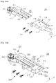
- FIGS. 11A to 11E are bottom perspective views showing a process in which a second bracket of the hinge bracket in accordance with the first embodiment is coupled to a first bracket in a refrigerator in accordance with one embodiment of the present invention.
- unillustrated reference numerals refer to FIGS. 1 to 4 , and FIGS. 9 and 10 .
- a process in which the second bracket 220 is coupled to the first bracket 210 is as follows.
- the second bracket 220 is disposed in front of the first bracket 210 so that the second portion 222 of the second bracket 220 faces the opening 214 of the first bracket 210.
- the second bracket 220 is made to approach the front surface of the first bracket 210 so that the second portion 222 is inserted into the opening 214 of the first bracket 210.
- the second bracket 220 is slid toward the rear of the main body 10.
- the second bracket 220 is slid toward the rear of the main body 10 in a state in which one surface of the second bracket 220 is fitted into the guide unit 216 of the first bracket 210.
- the movement of the second bracket 220 toward the rear of the main body 10 is limited by the fixing unit 240. That is, the movement of the second bracket 220 is limited by coupling of the fixing guide 241 to the fixing groove 242.
- the first bracket 210 and the second bracket 220 are connectable with each other by the coupling member 230.
- the first coupling hole 215 of the first bracket 210 and the second coupling hole 225 of the second bracket 220 are positioned on a straight line in the coupling direction E of the coupling member 230.
- the coupling member 230 sequentially passes through the first coupling hole 215 and the second coupling hole 225 and thereby the first bracket 210 and the second bracket 220 are coupled to each other.
- the door 30 is rotatably coupled to the main body 10 by coupling between the first bracket 210 and the second bracket 220.
- a process in which the second bracket 220 is separated from the first bracket 210 is as follows.
- the coupling member 230 that connects the first bracket 210 and the second bracket 220 while sequentially passing through the first coupling hole 215 and the second coupling hole 225 is removed.
- the second bracket 220 is slid toward the front of the main body 10.
- the second bracket 220 is slid toward the front of the main body 10 in a state in which one surface of the second bracket 220 is fitted into the guide unit 216 of the first bracket 210.
- the fixing groove 242 is separated from the fixing guide 241.
- the second portion 222 of the second bracket 220 is spaced apart from the opening 214 of the first bracket 210 toward the front of the main body 10, and therefore the second bracket 220 is separated from the first bracket 210.
- the door 30 may be separated from the main body 10 by separation between the first bracket 210 and the second bracket 220.
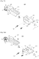
- FIG. 12 is a perspective view showing a hinge bracket in accordance with a second embodiment in a refrigerator in accordance with one embodiment of the present invention
- FIG. 13 is an exploded perspective view showing the hinge bracket in accordance with the second embodiment in a refrigerator in accordance with one embodiment of the present invention.
- unillustrated reference numerals refer to FIGS. 1 to 4 .
- at least one of the upper hinge 41 and the lower hinge 43 may have a form of a hinge bracket 300 in accordance with the second embodiment of the present invention.
- the door 30 should be separated from the main body 10.
- the hinge bracket 300 in accordance with the second embodiment of the present invention may be in a more preferable form at the lower hinge 43. Therefore, hereinafter, the hinge bracket 300 that is used at the lower hinge 43 will be the focus of the description. Hereinafter, repeated descriptions in FIGS. 9 to 11E will be omitted.
- the hinge bracket 300 connecting the door 30 and the main body 10 may include a first bracket 310 and a second bracket 320. Descriptions of the first bracket 310 and the second bracket 320 are the same as those in FIGS. 9 to 11E , and therefore will be omitted.
- the hinge bracket 300 may further include the coupling member 230 for allowing the first bracket 310 and the second bracket 320 to be coupled to each other. Description of the coupling member 230 is the same as that in FIGS. 9 to 11E , and therefore will be omitted.
- the hinge bracket 300 may further include a fixing unit 340.
- the fixing unit 340 may serve to fix the positions of the first bracket 310 and the second bracket 320 so that the first bracket 310 and the second bracket 320 are connectable with each other by the coupling member 230. Specifically, the fixing unit 340 may serve to fix the second bracket 320 to the first bracket 310 so that the first coupling hole 215 of the first bracket 310 and the second coupling hole 225 of the second bracket 320 are positioned on a straight line in the coupling direction E of the coupling member 230.
- the fixing unit 340 may include a fixing guide 341 and a fixing groove 342.
- the fixing guide 341 may be provided in any one of the first bracket 310 and the second bracket 320.
- the fixing groove 342 may be provided in the other one of the first bracket 310 and the second bracket 320 so as to be coupled to the fixing guide 341.
- the fixing guide 341 may be provided in any one of the body 211 of the first bracket 310 and one surface of the second bracket 320 facing the body 211.
- the fixing groove 342 may be provided in the other one of the body 211 of the first bracket 310 and the one surface of the second bracket 320 facing the body 211 so as to be coupled to the fixing guide 341.
- the fixing guide 341 may be provided in the body 211 of the first bracket 310 so as to be positioned between the first leg 212 and the second leg 213.
- the fixing groove 342 may be provided on the one surface of the second bracket 320 facing the body 211 so as to be coupled to the fixing guide 341.
- the fixing groove 342 may be provided in the rear of the second portion 222.
- the fixing groove 342 may have a shape recessed toward the inside of the second bracket 320.
- the fixing guide 341 may have a shape that extends from the body 211 toward the rear of the first bracket 310 and is bent. Specifically, the fixing guide 341 may have the shape that extends from the body 211 toward the rear of the first bracket 310 and is bent toward the same direction as the direction in which the plurality of legs 212 and 213 extend from the body 211. That is, the fixing guide 341 may have the shape that extends from the body 211 toward the rear of the first bracket 340 and is bent toward the lower side of the first bracket 340.
- the shapes of the fixing guide 341 and the fixing groove 342 may be variously modified.
- the fixing guide 341 may be fitted into and coupled to the fixing groove 342, but a coupling method between the fixing guide 341 and the fixing groove 342 is not limited thereto.
- the fixing unit 340 may serve to primarily fix the positions of the first bracket 310 and the second bracket 320 so that coupling between the first bracket 310 and the second bracket 320 is facilitated.
- the guide unit 216 of the first bracket 310 may serve to guide an insertion position of the second bracket 320 with respect to the first bracket 310. That is, the fixing unit 340 and the guide unit 216 of the first bracket 310 may reduce the number of coupling members 230 which are required in a coupling process of the first bracket 310 and the second bracket 320.
- the fixing unit 340 and the guide unit 216 of the first bracket 310 may primarily fix the positions of the first bracket 310 and the second bracket 320 so that coupling between the first bracket 310 and the second bracket 320 is accurately carried out by the coupling member 230, and therefore it is possible to enhance the binding force of the first bracket 310 and the second bracket 320.
- FIGS. 14A to 14D are bottom perspective views showing a process in which a second bracket of the hinge bracket in accordance with the second embodiment is coupled to a first bracket in a refrigerator in accordance with one embodiment of the present invention.
- unillustrated reference numerals refer to FIGS. 1 to 4 and FIGS. 12 and 13 .
- a process in which the second bracket 320 is coupled to the first bracket 310 is as follows.
- the second bracket 320 is disposed in front of the first bracket 310 so that the second portion 222 of the second bracket 320 may face the opening 214 of the first bracket 310.
- the second bracket 320 is made to approach the front surface of the first bracket 310 so that the second portion 222 of the second bracket 320 is inserted into the opening 214 of the first bracket 310.
- the second bracket 320 is slid toward the rear of the main body 10.
- the second bracket 320 is slid toward the rear of the main body 10 in a state in which one surface of the second bracket 320 is fitted into the guide unit 216 of the first bracket 310.
- the movement of the second bracket 320 toward the rear of the main body 10 is limited by the fixing unit 340. That is, the movement of the second bracket 320 is limited by coupling of the fixing guide 341 to the fixing groove 342.
- the first bracket 310 and the second bracket 320 are connectable with each other by the coupling member 230.
- the first coupling hole 215 of the first bracket 310 and the second coupling hole 225 of the second bracket 320 are positioned on a straight line in the coupling direction E of the coupling member 230.
- the coupling member 230 sequentially passes through the first coupling hole 215 and the second coupling hole 225 and thereby the first bracket 310 and the second bracket 320 are coupled to each other.
- the door 30 may be rotatably coupled to the main body 10 by coupling between the first bracket 310 and the second bracket 320.
- a process in which the second bracket 320 is separated from the first bracket 310 is as follows.
- the coupling member 230 that connects the first bracket 310 and the second bracket 320 while sequentially passing through the first coupling hole 215 and the second coupling hole 225 is removed.
- the second bracket 320 is slid toward the front of the main body 10.
- the second bracket 320 is slid toward the front of the main body 10 in a state in which the one surface of the second bracket 320 is fitted into the guide unit 216 of the first bracket 310.
- the fixing groove 342 is separated from the fixing guide 341.
- the second portion 222 of the second bracket 320 is spaced apart from the opening 214 of the first bracket 310 toward the front of the main body 10, and therefore the second bracket 320 is separated from the first bracket 310.
- the door 30 may be separated from the main body 10 by separation between the first bracket 310 and the second bracket 320.
- FIG. 15 is a perspective view showing a hinge bracket in a refrigerator according to an illustrative example that does not form part of the claimed invention
- FIG. 16 is an exploded perspective view showing the hinge bracket in a refrigeratoraccording to an illustrative example that does not form part of the claimed invention
- unillustrated reference numerals refer to FIGS. 1 to 4
- at least one of the upper hinge 41 and the lower hinge 43 may have a form of a hinge bracket 400according to an illustrative example .
- the door 30 should be separated from the main body 10.
- the hinge bracket 400 according to an illustrative example may be in a more preferable form at the lower hinge 43. Therefore, hereinafter, the hinge bracket 400 that is used at the lower hinge 43 will be the focus of the description.
- the hinge bracket 400 connecting the door 30 and the main body 10 may include a first bracket 410 and a second bracket 420.
- the first bracket 410 may be coupled to the main body 10.
- the first bracket 410 may be coupled to the lower side of the main body 10.
- the first bracket 410 may include frames 411, 412, and 413 that form an exterior appearance.
- the frames 411, 412, and 413 may include a top frame 411 forming a top surface of the first bracket 410, a rear frame 412 forming a rear surface of the first bracket 410, and a side frame 413 (see FIG. 17A ) forming one side surface of the first bracket 410.
- the top frame 411 may face the lower side of the main body 10, that is, the bottom surface of the main body 10.
- a first coupling hole 215 to which the coupling member 230 is coupled may be formed in the side frame 413.
- the first bracket 410 may further include a side opening 414.
- the side opening 414 may face the side frame 413.
- the side opening 414 may be open toward the outside of the main body 10.
- the side opening 414 may be provided in the first bracket 410 toward the outside of the main body 10
- the side frame 413 may be provided in the first bracket 410 toward the inside of the main body 10.
- the second bracket 420 may be coupled to the door 30. Specifically, the second bracket 420 may be coupled to the lower side of the door 30 so as to correspond to the first bracket 410.
- the second bracket 420 may be detachably coupled to the first bracket 410.
- the second bracket 420 may be detachably coupled to the first bracket 410 in left and right directions.
- the second bracket 420 may be slidably coupled to the first bracket 410.
- the second bracket 420 may be slidably coupled to the inner side of the first bracket 410.
- the second bracket 420 may be slidably coupled to the first bracket 410 in a direction from the side opening 414 to the inside of the main body 10.
- the second bracket 420 may be slidably coupled to the first bracket 410 in a direction from the side opening 414 to the side frame 413.
- the second bracket 420 may include the first portion 221 and the second portion 222.
- the first portion 221 may face the door 30.
- the adjustment portion 223 for adjusting the height or level of the refrigerator 1 may be installed in the first portion 221.
- the height or level of the refrigerator 1 may be adjusted by rotating the adjustment portion 223. As an example, when the adjustment portion 223 is rotated in the clockwise direction, the height of the refrigerator 1 may be increased. When the adjustment portion 223 is rotated in the counterclockwise direction, the height of the refrigerator 1 may be reduced.
- a method of adjusting the height or level of the refrigerator 1 is not limited thereto, and may be variously modified.
- the adjustment portion 223 may connect the second bracket 420 and the door 30.
- the second portion 222 may extend from the first portion 221 toward the main body 10.
- the second portion 222 may be coupled to the first bracket 410. Specifically, the second portion 222 may be inserted into the side opening 414 of the first bracket 410 and moved toward the inside of the main body 10.
- the first portion 221 of the second bracket 420 may be positioned in front of the first bracket 410, and the second portion 222 of the second bracket 420 may be positioned inside the first bracket 410.
- the second coupling hole 225 may be formed in one surface of the second bracket 420. Specifically, the second coupling hole 225 corresponding to the first coupling hole 215 may be formed in one surface of the second bracket 420 facing the side opening 414. In other words, the second coupling hole 225 may be formed in the one surface of the second portion 222 facing the side opening 414.
- the shape and number of the second coupling holes 225 may correspond to the shape and number of the first coupling holes 215.
- the shape and number of the first coupling holes 215 and the second coupling holes 225 may correspond to the shape and number of the coupling members 230.
- the hinge bracket 300 may further include the coupling member 230 for allowing the first bracket 410 and the second bracket 420 to be coupled to each other.
- the coupling member 230 may couple the first bracket 410 and the second bracket 420 to other by passing through the first bracket 410 and the second bracket 420.
- a coupling direction E of the coupling member 230 with respect to the first bracket 410 and the second bracket 420 may coincide with a coupling direction of the second bracket 420 with respect to the first bracket 410.
- the coupling member 230 may pass through one surface of the first bracket 410 positioned on a downstream side in the coupling direction E of the coupling member 230 and one surface of the second bracket 420 positioned on an upstream side in the coupling direction E of the coupling member 230.
- the coupling member 230 may pass through the side frame 413 of the first bracket 410 and the one surface of the second bracket 420 facing the side opening 414 of the first bracket 410.
- the load of the main body 10 and the door 30 of the refrigerator 1 may be distributed to the first bracket 410, the second bracket 420, and the coupling member 230, and therefore it is possible to improve the durability of the hinge bracket 400.
- the coupling member 230 that sequentially passes through the second coupling hole 225 of the second bracket 420 and the first coupling hole 215 of the first bracket 410 may be coupled to a fastening member 450.
- the coupling member 230 may correspond to a bolt and the fastening member 450 may correspond to a nut.
- the number and shape of the coupling members 230 may be variously modified.
- the hinge bracket 400 may further include a fixing unit 440.
- the fixing unit 440 may serve to fix the positions of the first bracket 410 and the second bracket 420 so that the first bracket 410 and the second bracket 420 are connectable with each other by the coupling member 230. Specifically, the fixing unit 440 may serve to fix the second bracket 420 to the first bracket 410 so that the first coupling hole 215 of the first bracket 410 and the second coupling hole 225 of the second bracket 420 are positioned on a straight line in the coupling direction E of the coupling member 230.
- the fixing unit 440 may include a fixing guide 441 and a fixing groove 442.
- the fixing guide 441 may be provided in any one of the first bracket 410 and the second bracket 420.
- the fixing groove 442 may be provided in the other one of the first bracket 410 and the second bracket 420 so that the fixing guide 441 may be fastened to the fixing groove 442.
- the fixing guide 441 may be provided in any one of the top frame 411 of the first bracket 410 and one surface of the second bracket 420 facing the top frame 411.
- the fixing groove 442 may be provided in the other one of the top frame 411 of the first bracket 410 and the one surface of the second bracket 420 facing the top frame 411 so as to be coupled to the fixing guide 441.
- the fixing guide 441 may be provided in the top frame 411 of the first bracket 410.
- the fixing guide 441 may be provided in the top frame 411 of the first bracket 410 so as to protrude toward the same direction as a direction in which the rear frame 412 and the side frame 413 extend from the top frame 411.
- the fixing groove 442 may be provided on the one surface of the second bracket 420 facing the top frame 411 so as to be coupled to the fixing guide 441.
- the fixing groove 442 may be provided in the second portion 222 of the second bracket 420 facing the top frame 411.
- the fixing guide 441 may have a pin shape that protrudes from the top frame 411 toward the lower side of the first bracket 410.
- the fixing guide 441 may have the pin shape that protrudes from the top frame 411 so as to face the same direction as the direction in which the rear frame 412 and the side frame 413 extend from the top frame 411.
- the fixing guide 411 may include a head 241a and a neck 241b.
- the head 241a and the neck 241b may have different widths from each other. Specifically, the neck 241b may have a smaller width than that of the head 241a.
- the neck 241b may connect any one of the first bracket 410 and the second bracket 420 and the head 241a.
- the neck 241b may connect the top frame 411 of the first bracket 410 and the head 241a.
- the fixing groove 442 may include a fastening unit 442a and a locking unit 442b.
- the fastening unit 442a may be provided in such a manner that the head 241a may pass through the fastening unit 442a.
- the locking unit 442b may be coupled to the neck 241b so that the fixing guide 441 may be fixed to the fixing groove 442 and connected to the fastening unit 442a.
- the fastening unit 442a and the locking unit 442b may have different widths from each other.
- the fastening unit 442a may have a larger width than that of the head 241a in such a manner that the head 241a may be coupled to or separated from the fastening unit 442a
- the locking unit 442b may have a smaller width than that of the head 241a so as to prevent the head 241a from being separated from the fixing groove 442.
- the fastening unit 442a and the locking unit 442b may be connected to each other in such a manner that the fixing guide 441 may be moved between the fastening unit 442a and the locking unit 442b.
- the neck 241b of the fixing guide 441 may be coupled to the locking unit 442b so that the fixing guide 441 may be fixed to the fixing groove 442.
- the fastening unit 442a and the locking unit 442b may have different shapes from each other.
- the fastening unit 442a may have a shape corresponding to the head 241a so that the head 241a may pass through the fastening unit 442a.
- the locking unit 442b may have a shape corresponding to the neck 241b so as to grasp and fix the outer surface of the neck 241b.
- the fastening unit 442a may have a larger width than that of the locking unit 442b coupled to the neck 241b in such a manner that the head 241a having a larger width than that of the neck 241b may pass through the fastening unit 442a.
- the second bracket 420 When the second bracket 420 is slid in the coupling direction E of the coupling member 230 in a state in which the head 241a passes through the fastening unit 442a, the second bracket 420 may be fixed to the first bracket 410 by coupling between the neck 241b and the locking unit 442b.
- the fixing unit 440 may serve to primarily fix the positions of the first bracket 410 and the second bracket 420 so that the coupling between the first bracket 410 and the second bracket 420 is facilitated. Accordingly, the fixing unit 440 may primarily fix the positions of the first bracket 410 and the second bracket 420 so that the coupling between the first bracket 410 and the second bracket 420 is accurately carried out by the coupling member 230, and therefore it is possible to enhance the binding force of the first bracket 410 and the second bracket 420.
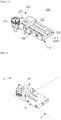
- FIGS. 17A to 17D are bottom perspective views showing a process in which a second bracket of the hinge bracket according to an illustrative example that does not form part of the claimed invention in a refrigerator.
- unillustrated reference numerals refer to FIGS. 1 to 4 and FIGS. 15 and 16 .
- a process in which the second bracket 420 is coupled to the first bracket 410 is as follows.
- the second bracket 420 is made to approach the first bracket 410 so that the fixing groove 442 and the fixing guide 441 face each other.
- the second bracket 420 is made to approach the first bracket 410 so that the second portion 222 of the second bracket 420 faces the top frame 411 of the first bracket 410.
- the second bracket 420 When the second bracket 420 is slid in the first direction A, the head 241a is positioned on a lower side of the locking unit 442b, and the neck 241b connected to the head 241a is coupled to the locking unit 442b, and therefore the second bracket 420 is fixed to the first bracket 410.
- the first bracket 410 and the second bracket 420 may be connectable with each other by the coupling member 230.
- the first coupling hole 215 of the first bracket 410 and the second coupling hole 225 of the second bracket 420 are positioned on a straight line in the coupling direction E of the coupling member 230.
- the coupling member 230 sequentially passes through the second coupling hole 225 and the first coupling hole 215 and thereby the first bracket 410 and the second bracket 420 are coupled to each other.
- the coupling member 230 that has sequentially passed through the second coupling hole 225 and the first coupling hole 215 is coupled to the fastening member 450.
- the door 30 may be rotatably coupled to the main body 10 by coupling between the first bracket 410 and the second bracket 420.
- a process in which the second bracket 420 is separated from the first bracket 410 is as follows.
- the fastening member 450 is separated from the coupling member 230.
- the coupling member 230 that has sequentially passed through the second coupling hole 225 and the first coupling hole 215 is removed.
- the second bracket 420 is slid in the second direction B, the head 241a is positioned on the lower side of the fastening unit 442a, and the neck 241b is spaced apart from the locking unit 442b.
- the fixing guide 441 is positioned on a straight line with the fastening unit 442a.
- the second bracket 420 is moved toward the lower side of the main body 10, the second bracket 420 is separated from the first bracket 410 while the fixing guide 441 is spaced apart from the fixing groove 442.
- the first direction A and the second direction B may be opposite to each other.
- the first direction A indicates the right direction and the second direction B indicates the left direction.
Landscapes
- Engineering & Computer Science (AREA)
- Mechanical Engineering (AREA)
- Physics & Mathematics (AREA)
- Thermal Sciences (AREA)
- Chemical & Material Sciences (AREA)
- Combustion & Propulsion (AREA)
- General Engineering & Computer Science (AREA)
- Refrigerator Housings (AREA)
- Hinges (AREA)
Claims (8)
- Kühlschrank (1), umfassend:einen Hauptkörper (10), der eine äußere Erscheinung ausbildet;ein Lagerfach (20), das im Innern des Hauptkörpers (10) vorgesehen ist;eine Tür (30), die drehbar mit dem Hauptkörper (10) gekoppelt ist, sodass sie eine offene Vorderfläche (111) des Lagerfachs (20) öffnet und schließt; undeinen Scharnierbügel (200, 300), der den Hauptkörper (10) und die Tür (30) verbindet,wobei der Scharnierbügel (200, 300) einen ersten Bügel (210, 310), der mit dem Hauptkörper (10) gekoppelt ist, und einen zweiten Bügel (220, 320), der mit der Tür (30) gekoppelt und lösbar mit dem ersten Bügel (210, 310) gekoppelt ist, umfasst,wobei der erste Bügel (210, 310) einen Körper (211), der so angeordnet ist, dass er dem Hauptkörper (10) zugewandt ist, und eine Mehrzahl von Schenkeln (212, 213), die sich von dem Körper (211) erstrecken und zusammen mit dem Körper (211) eine Öffnung in Richtung einer Vorderseite des ersten Bügels (210, 310) ausbilden, sodass der zweite Bügel (220, 230) in die Öffnung einsetzbar ist, umfasst,wobei der zweite Bügel (220, 320) verschiebbar mit einer Innenseite des ersten Bügels (210, 310) gekoppelt ist und der Scharnierbügel (200, 300) ferner ein Kopplungselement (230) umfasst, das den zweiten Bügel (220, 320) mit mindestens einer Fläche des ersten Bügels (210, 310) koppelt, undwobei der Scharnierbügel (200, 300) ferner eine Fixiereinheit (240, 340) umfasst, die Positionen des ersten Bügels (210, 310) und des zweiten Bügels (220, 320) fixiert, sodass der erste Bügel (210, 310) und der zweite Bügel (220, 320) durch das Kopplungselement (230) miteinander verbindbar sind, undwobei die Mehrzahl von Schenkeln (212, 213) einen ersten Schenkel (212) umfasst, in dem eine erste Kopplungsbohrung (215) ausgebildet ist, mit der das Kopplungselement (230) gekoppelt wird,dadurch gekennzeichnet, dassdie Fixiereinheit (240, 340) eine Fixierführung (241, 341), die in dem Körper (211) des ersten Bügels (210, 310) so vorgesehen ist, dass sie in dieselbe Richtung vorsteht wie eine Richtung, in die die Mehrzahl von Schenkeln (212, 213) sich von dem Körper (211) erstrecken, und eine Fixiernut (242, 342), die in einer Fläche des zweiten Bügels (220, 320) vorgesehen ist, die dem Körper (211) zugewandt ist, sodass die Fixierführung (241, 341) an der Fixiernut (242, 342) befestigt wird, umfasst.
- Kühlschrank (1) nach Anspruch 1, wobei der zweite Bügel (220, 320) in Vorwärts- und Rückwärtsrichtung lösbar mit dem ersten Bügel (210, 310) gekoppelt ist.
- Kühlschrank (1) nach Anspruch 1, wobei die Mehrzahl von Schenkeln (212, 213) ferner einen zweiten Schenkel (213) umfasst, der dem ersten Schenkel (212) zugewandt ist und in dem eine Führungseinheit (216) zum Führen der Bewegung des zweiten Bügels (220, 320) ausgebildet ist, und die Führungseinheit (216) an einer Innenwand des zweiten Schenkels (213) ausgespart ist.
- Kühlschrank (1) nach Anspruch 1, wobei in einer Fläche des zweiten Bügels (220), die dem ersten Schenkel (212) zugewandt ist, eine zweite Kopplungsbohrung (225) ausgebildet ist, die der ersten Kopplungsbohrung (215) entspricht, und der erste Bügel (210) und der zweite Bügel (220) dadurch miteinander gekoppelt werden, dass das Kopplungselement (230) die erste Kopplungsbohrung (215) und die zweite Kopplungsbohrung (225) durchdringt.
- Kühlschrank (1) nach Anspruch 4, wobei die Fixiereinheit (240) den zweiten Bügel (220) an dem ersten Bügel (210) so fixiert, dass die erste Kopplungsbohrung (215) und die zweite Kopplungsbohrung (225) in einer Kopplungsrichtung des Kopplungselements (230) auf einer geraden Linie angeordnet sind.
- Kühlschrank (1) nach Anspruch 5, wobei die Fixierführung (341) eine Form aufweist, die sich von dem Körper (211) in Richtung einer hinteren Seite des ersten Bügels (310) erstreckt und gebogen ist.
- Kühlschrank nach Anspruch 5, wobei die Fixierführung (341) eine Stiftform aufweist, die von dem Körper (211) in Richtung einer unteren Seite des ersten Bügels (310) vorsteht.
- Kühlschrank (1) nach Anspruch 7, wobei die Fixierführung (241) Folgendes umfasst:einen Kopf (241a) undeinen Hals (241b), der eine geringere Breite als die des Kopfes (241a) aufweist,sodass er an der Fixiernut (242) befestigt wird, und den Kopf (241a) und den Körper (211) verbindet.
Applications Claiming Priority (2)
| Application Number | Priority Date | Filing Date | Title |
|---|---|---|---|
| KR20130145018 | 2013-11-27 | ||
| PCT/KR2014/011445 WO2015080477A1 (ko) | 2013-11-27 | 2014-11-26 | 냉장고 |
Publications (3)
| Publication Number | Publication Date |
|---|---|
| EP3076113A1 EP3076113A1 (de) | 2016-10-05 |
| EP3076113A4 EP3076113A4 (de) | 2017-07-26 |
| EP3076113B1 true EP3076113B1 (de) | 2022-04-27 |
Family
ID=53182068
Family Applications (1)
| Application Number | Title | Priority Date | Filing Date |
|---|---|---|---|
| EP14865585.5A Not-in-force EP3076113B1 (de) | 2013-11-27 | 2014-11-26 | Kühlschrank |
Country Status (5)
| Country | Link |
|---|---|
| US (2) | US20150145400A1 (de) |
| EP (1) | EP3076113B1 (de) |
| KR (1) | KR102267886B1 (de) |
| CN (1) | CN105765327B (de) |
| WO (1) | WO2015080477A1 (de) |
Families Citing this family (4)
| Publication number | Priority date | Publication date | Assignee | Title |
|---|---|---|---|---|
| KR102494128B1 (ko) * | 2017-12-01 | 2023-02-01 | 엘지전자 주식회사 | 냉장고 |
| US11015377B2 (en) | 2019-08-26 | 2021-05-25 | Whirlpool Corporation | Hinge assembly |
| EP4130622A4 (de) * | 2020-04-17 | 2023-08-23 | Samsung Electronics Co., Ltd. | Kühlschrank |
| CN114061227B (zh) * | 2020-07-30 | 2023-12-22 | Lg电子株式会社 | 多关节连杆铰链和包括该多关节连杆铰链的冰箱 |
Citations (1)
| Publication number | Priority date | Publication date | Assignee | Title |
|---|---|---|---|---|
| US4407044A (en) * | 1979-08-18 | 1983-10-04 | Ohta Company Limited | Hinge |
Family Cites Families (25)
| Publication number | Priority date | Publication date | Assignee | Title |
|---|---|---|---|---|
| US2211581A (en) * | 1938-01-20 | 1940-08-13 | Robert A Ross | Hinge |
| US4170391A (en) * | 1978-09-21 | 1979-10-09 | General Electric Company | Refrigerator cabinet construction |
| US4536904A (en) * | 1982-10-07 | 1985-08-27 | Leggett & Platt, Incorporated | Foldable bed frame |
| DE3630234C2 (de) * | 1986-09-05 | 1994-04-28 | Simonswerk Gmbh | Vorrichtung zur Befestigung eines Tür- oder Fensterbandes |
| US4932729A (en) * | 1989-11-13 | 1990-06-12 | White Consolidated Industries, Inc. | Door hinge and cabinet support mounting bracket |
| US5193308A (en) * | 1992-07-22 | 1993-03-16 | The Stanley Works | Snap-in hinge for doors with hollow metal frames |
| US5361455A (en) * | 1992-12-29 | 1994-11-08 | Ran Enterprises, Inc. | Hinge |
| US5408725A (en) * | 1993-04-20 | 1995-04-25 | Maytag Corporation | Hinge assembly |
| KR0169462B1 (ko) * | 1996-10-08 | 1999-10-01 | 삼성전자주식회사 | 냉장고 |
| KR100200797B1 (ko) * | 1997-03-06 | 1999-06-15 | 윤종용 | 냉장고 |
| AU733320B2 (en) * | 1997-08-09 | 2001-05-10 | Lg Electronics Inc. | Door hinge fixing structure for refrigerator |
| KR100277591B1 (ko) * | 1997-09-29 | 2001-03-02 | 윤종용 | 냉장고 |
| KR100249364B1 (ko) * | 1997-10-09 | 2000-04-01 | 구자홍 | 냉장고의 힌지 구조 |
| SI20218B (sl) * | 1999-04-30 | 2006-04-30 | Mednarodno Podjetje Lama D.D. Okovja - Montazni Sistemi - Orodja - Trgovina, Dekani | Osnovna plosca za sarnir |
| KR200202532Y1 (ko) * | 2000-06-07 | 2000-11-15 | 대우전자주식회사 | 탈부착이 용이한 냉장고 도어 힌지 |
| US7192105B2 (en) * | 2000-08-10 | 2007-03-20 | Samsung Electronics Co., Ltd. | Door control device for refrigerators and refrigerator with the device |
| JP2004293913A (ja) * | 2003-03-26 | 2004-10-21 | Sanyo Electric Co Ltd | 冷蔵庫 |
| KR101164823B1 (ko) * | 2005-06-24 | 2012-07-12 | 삼성전자주식회사 | 냉장고 |
| CN101398248B (zh) * | 2007-09-28 | 2010-11-03 | 博西华家用电器有限公司 | 家用电器 |
| KR20100019616A (ko) * | 2008-08-11 | 2010-02-19 | 삼성전자주식회사 | 냉장고 |
| KR101786966B1 (ko) * | 2010-08-06 | 2017-10-19 | 삼성전자주식회사 | 냉장고 |
| KR101506145B1 (ko) * | 2010-08-11 | 2015-03-27 | 삼성전자 주식회사 | 냉장고 |
| DE102010039743A1 (de) | 2010-08-25 | 2012-03-01 | BSH Bosch und Siemens Hausgeräte GmbH | Kältegerät, insbesondere Haushaltskältegerät |
| US8491070B2 (en) * | 2010-10-04 | 2013-07-23 | General Electric Company | Refrigerator door pocket hinge assembly |
| KR20130021670A (ko) * | 2011-08-23 | 2013-03-06 | 위니아만도 주식회사 | 냉장고 도어 힌지어셈블리 |
-
2014
- 2014-11-25 US US14/552,934 patent/US20150145400A1/en not_active Abandoned
- 2014-11-26 US US15/039,909 patent/US10724782B2/en active Active
- 2014-11-26 EP EP14865585.5A patent/EP3076113B1/de not_active Not-in-force
- 2014-11-26 CN CN201480063890.9A patent/CN105765327B/zh not_active Expired - Fee Related
- 2014-11-26 KR KR1020167002512A patent/KR102267886B1/ko not_active Expired - Fee Related
- 2014-11-26 WO PCT/KR2014/011445 patent/WO2015080477A1/ko not_active Ceased
Patent Citations (1)
| Publication number | Priority date | Publication date | Assignee | Title |
|---|---|---|---|---|
| US4407044A (en) * | 1979-08-18 | 1983-10-04 | Ohta Company Limited | Hinge |
Also Published As
| Publication number | Publication date |
|---|---|
| WO2015080477A1 (ko) | 2015-06-04 |
| KR102267886B1 (ko) | 2021-06-23 |
| US10724782B2 (en) | 2020-07-28 |
| KR20160100292A (ko) | 2016-08-23 |
| CN105765327B (zh) | 2018-11-20 |
| CN105765327A (zh) | 2016-07-13 |
| EP3076113A1 (de) | 2016-10-05 |
| US20150145400A1 (en) | 2015-05-28 |
| US20170003067A1 (en) | 2017-01-05 |
| EP3076113A4 (de) | 2017-07-26 |
Similar Documents
| Publication | Publication Date | Title |
|---|---|---|
| US9353985B2 (en) | Refrigerator | |
| EP1903288B1 (de) | Schubladentür und Kühlschrank damit | |
| KR101880085B1 (ko) | 냉장고 | |
| KR101849106B1 (ko) | 냉장고 | |
| EP2770285B1 (de) | Kühlschrank | |
| US8220888B2 (en) | Storage with a symmetric hinge assembly | |
| EP3076113B1 (de) | Kühlschrank | |
| US10436500B2 (en) | Refrigerator | |
| US20080203875A1 (en) | Refrigerator | |
| US20130270989A1 (en) | Sliding apparatus and refrigerator having the same | |
| US20120062093A1 (en) | Refrigerator | |
| US9726423B1 (en) | Sliding shelf assembly for a refrigerator appliance | |
| EP2573491A2 (de) | Kühlschrank | |
| US20060152119A1 (en) | Refrigerator | |
| EP2455693A2 (de) | Kühlschrank und Behälteranordnung dafür | |
| US12044462B2 (en) | Refrigerator | |
| US9310126B2 (en) | Refrigerator | |
| KR20120084215A (ko) | 서랍식 냉장고 | |
| US20110315694A1 (en) | Refrigerator | |
| US20140203698A1 (en) | Refrigerator | |
| EP3671084B1 (de) | Kühlschrank | |
| KR20140134865A (ko) | 냉장고 | |
| US11988437B2 (en) | Refrigerator | |
| KR101161120B1 (ko) | 냉장고용 식품 수납장치 및 이를 갖는 냉장고 | |
| KR101273655B1 (ko) | 김치냉장고 |
Legal Events
| Date | Code | Title | Description |
|---|---|---|---|
| PUAI | Public reference made under article 153(3) epc to a published international application that has entered the european phase |
Free format text: ORIGINAL CODE: 0009012 |
|
| 17P | Request for examination filed |
Effective date: 20160315 |
|
| AK | Designated contracting states |
Kind code of ref document: A1 Designated state(s): AL AT BE BG CH CY CZ DE DK EE ES FI FR GB GR HR HU IE IS IT LI LT LU LV MC MK MT NL NO PL PT RO RS SE SI SK SM TR |
|
| AX | Request for extension of the european patent |
Extension state: BA ME |
|
| DAX | Request for extension of the european patent (deleted) | ||
| A4 | Supplementary search report drawn up and despatched |
Effective date: 20170628 |
|
| RIC1 | Information provided on ipc code assigned before grant |
Ipc: E05D 5/04 20060101ALI20170620BHEP Ipc: E05D 7/081 20060101ALI20170620BHEP Ipc: E05D 7/12 20060101ALI20170620BHEP Ipc: E05D 11/08 20060101ALI20170620BHEP Ipc: F25D 23/02 20060101AFI20170620BHEP |
|
| STAA | Information on the status of an ep patent application or granted ep patent |
Free format text: STATUS: EXAMINATION IS IN PROGRESS |
|
| 17Q | First examination report despatched |
Effective date: 20190102 |
|
| GRAP | Despatch of communication of intention to grant a patent |
Free format text: ORIGINAL CODE: EPIDOSNIGR1 |
|
| STAA | Information on the status of an ep patent application or granted ep patent |
Free format text: STATUS: GRANT OF PATENT IS INTENDED |
|
| INTG | Intention to grant announced |
Effective date: 20220208 |
|
| RIN1 | Information on inventor provided before grant (corrected) |
Inventor name: JEONG, KYUNG HAN Inventor name: LEE, JEA WON Inventor name: IGOR, IVANOV Inventor name: TELEGIN, YURY Inventor name: KYONG, YONG SOO Inventor name: EOM, TAE IN Inventor name: KANG, SUNG WOOK Inventor name: LEE, JEE HOON |
|
| GRAS | Grant fee paid |
Free format text: ORIGINAL CODE: EPIDOSNIGR3 |
|
| GRAA | (expected) grant |
Free format text: ORIGINAL CODE: 0009210 |
|
| STAA | Information on the status of an ep patent application or granted ep patent |
Free format text: STATUS: THE PATENT HAS BEEN GRANTED |
|
| AK | Designated contracting states |
Kind code of ref document: B1 Designated state(s): AL AT BE BG CH CY CZ DE DK EE ES FI FR GB GR HR HU IE IS IT LI LT LU LV MC MK MT NL NO PL PT RO RS SE SI SK SM TR |
|
| REG | Reference to a national code |
Ref country code: GB Ref legal event code: FG4D |
|
| REG | Reference to a national code |
Ref country code: CH Ref legal event code: EP |
|
| REG | Reference to a national code |
Ref country code: DE Ref legal event code: R096 Ref document number: 602014083464 Country of ref document: DE |
|
| REG | Reference to a national code |
Ref country code: AT Ref legal event code: REF Ref document number: 1487219 Country of ref document: AT Kind code of ref document: T Effective date: 20220515 |
|
| REG | Reference to a national code |
Ref country code: IE Ref legal event code: FG4D |
|
| REG | Reference to a national code |
Ref country code: LT Ref legal event code: MG9D |
|
| REG | Reference to a national code |
Ref country code: NL Ref legal event code: MP Effective date: 20220427 |
|
| REG | Reference to a national code |
Ref country code: AT Ref legal event code: MK05 Ref document number: 1487219 Country of ref document: AT Kind code of ref document: T Effective date: 20220427 |
|
| PG25 | Lapsed in a contracting state [announced via postgrant information from national office to epo] |
Ref country code: NL Free format text: LAPSE BECAUSE OF FAILURE TO SUBMIT A TRANSLATION OF THE DESCRIPTION OR TO PAY THE FEE WITHIN THE PRESCRIBED TIME-LIMIT Effective date: 20220427 |
|
| PG25 | Lapsed in a contracting state [announced via postgrant information from national office to epo] |
Ref country code: SE Free format text: LAPSE BECAUSE OF FAILURE TO SUBMIT A TRANSLATION OF THE DESCRIPTION OR TO PAY THE FEE WITHIN THE PRESCRIBED TIME-LIMIT Effective date: 20220427 Ref country code: PT Free format text: LAPSE BECAUSE OF FAILURE TO SUBMIT A TRANSLATION OF THE DESCRIPTION OR TO PAY THE FEE WITHIN THE PRESCRIBED TIME-LIMIT Effective date: 20220829 Ref country code: NO Free format text: LAPSE BECAUSE OF FAILURE TO SUBMIT A TRANSLATION OF THE DESCRIPTION OR TO PAY THE FEE WITHIN THE PRESCRIBED TIME-LIMIT Effective date: 20220727 Ref country code: LT Free format text: LAPSE BECAUSE OF FAILURE TO SUBMIT A TRANSLATION OF THE DESCRIPTION OR TO PAY THE FEE WITHIN THE PRESCRIBED TIME-LIMIT Effective date: 20220427 Ref country code: HR Free format text: LAPSE BECAUSE OF FAILURE TO SUBMIT A TRANSLATION OF THE DESCRIPTION OR TO PAY THE FEE WITHIN THE PRESCRIBED TIME-LIMIT Effective date: 20220427 Ref country code: GR Free format text: LAPSE BECAUSE OF FAILURE TO SUBMIT A TRANSLATION OF THE DESCRIPTION OR TO PAY THE FEE WITHIN THE PRESCRIBED TIME-LIMIT Effective date: 20220728 Ref country code: FI Free format text: LAPSE BECAUSE OF FAILURE TO SUBMIT A TRANSLATION OF THE DESCRIPTION OR TO PAY THE FEE WITHIN THE PRESCRIBED TIME-LIMIT Effective date: 20220427 Ref country code: ES Free format text: LAPSE BECAUSE OF FAILURE TO SUBMIT A TRANSLATION OF THE DESCRIPTION OR TO PAY THE FEE WITHIN THE PRESCRIBED TIME-LIMIT Effective date: 20220427 Ref country code: BG Free format text: LAPSE BECAUSE OF FAILURE TO SUBMIT A TRANSLATION OF THE DESCRIPTION OR TO PAY THE FEE WITHIN THE PRESCRIBED TIME-LIMIT Effective date: 20220727 Ref country code: AT Free format text: LAPSE BECAUSE OF FAILURE TO SUBMIT A TRANSLATION OF THE DESCRIPTION OR TO PAY THE FEE WITHIN THE PRESCRIBED TIME-LIMIT Effective date: 20220427 |
|
| PG25 | Lapsed in a contracting state [announced via postgrant information from national office to epo] |
Ref country code: RS Free format text: LAPSE BECAUSE OF FAILURE TO SUBMIT A TRANSLATION OF THE DESCRIPTION OR TO PAY THE FEE WITHIN THE PRESCRIBED TIME-LIMIT Effective date: 20220427 Ref country code: PL Free format text: LAPSE BECAUSE OF FAILURE TO SUBMIT A TRANSLATION OF THE DESCRIPTION OR TO PAY THE FEE WITHIN THE PRESCRIBED TIME-LIMIT Effective date: 20220427 Ref country code: LV Free format text: LAPSE BECAUSE OF FAILURE TO SUBMIT A TRANSLATION OF THE DESCRIPTION OR TO PAY THE FEE WITHIN THE PRESCRIBED TIME-LIMIT Effective date: 20220427 Ref country code: IS Free format text: LAPSE BECAUSE OF FAILURE TO SUBMIT A TRANSLATION OF THE DESCRIPTION OR TO PAY THE FEE WITHIN THE PRESCRIBED TIME-LIMIT Effective date: 20220827 |
|
| REG | Reference to a national code |
Ref country code: DE Ref legal event code: R097 Ref document number: 602014083464 Country of ref document: DE |
|
| PG25 | Lapsed in a contracting state [announced via postgrant information from national office to epo] |
Ref country code: SM Free format text: LAPSE BECAUSE OF FAILURE TO SUBMIT A TRANSLATION OF THE DESCRIPTION OR TO PAY THE FEE WITHIN THE PRESCRIBED TIME-LIMIT Effective date: 20220427 Ref country code: SK Free format text: LAPSE BECAUSE OF FAILURE TO SUBMIT A TRANSLATION OF THE DESCRIPTION OR TO PAY THE FEE WITHIN THE PRESCRIBED TIME-LIMIT Effective date: 20220427 Ref country code: RO Free format text: LAPSE BECAUSE OF FAILURE TO SUBMIT A TRANSLATION OF THE DESCRIPTION OR TO PAY THE FEE WITHIN THE PRESCRIBED TIME-LIMIT Effective date: 20220427 Ref country code: EE Free format text: LAPSE BECAUSE OF FAILURE TO SUBMIT A TRANSLATION OF THE DESCRIPTION OR TO PAY THE FEE WITHIN THE PRESCRIBED TIME-LIMIT Effective date: 20220427 Ref country code: DK Free format text: LAPSE BECAUSE OF FAILURE TO SUBMIT A TRANSLATION OF THE DESCRIPTION OR TO PAY THE FEE WITHIN THE PRESCRIBED TIME-LIMIT Effective date: 20220427 Ref country code: CZ Free format text: LAPSE BECAUSE OF FAILURE TO SUBMIT A TRANSLATION OF THE DESCRIPTION OR TO PAY THE FEE WITHIN THE PRESCRIBED TIME-LIMIT Effective date: 20220427 |
|
| PGFP | Annual fee paid to national office [announced via postgrant information from national office to epo] |
Ref country code: DE Payment date: 20220621 Year of fee payment: 9 |
|
| PLBE | No opposition filed within time limit |
Free format text: ORIGINAL CODE: 0009261 |
|
| STAA | Information on the status of an ep patent application or granted ep patent |
Free format text: STATUS: NO OPPOSITION FILED WITHIN TIME LIMIT |
|
| PG25 | Lapsed in a contracting state [announced via postgrant information from national office to epo] |
Ref country code: AL Free format text: LAPSE BECAUSE OF FAILURE TO SUBMIT A TRANSLATION OF THE DESCRIPTION OR TO PAY THE FEE WITHIN THE PRESCRIBED TIME-LIMIT Effective date: 20220427 |
|
| 26N | No opposition filed |
Effective date: 20230130 |
|
| PG25 | Lapsed in a contracting state [announced via postgrant information from national office to epo] |
Ref country code: SI Free format text: LAPSE BECAUSE OF FAILURE TO SUBMIT A TRANSLATION OF THE DESCRIPTION OR TO PAY THE FEE WITHIN THE PRESCRIBED TIME-LIMIT Effective date: 20220427 |
|
| PG25 | Lapsed in a contracting state [announced via postgrant information from national office to epo] |
Ref country code: MC Free format text: LAPSE BECAUSE OF FAILURE TO SUBMIT A TRANSLATION OF THE DESCRIPTION OR TO PAY THE FEE WITHIN THE PRESCRIBED TIME-LIMIT Effective date: 20220427 |
|
| REG | Reference to a national code |
Ref country code: CH Ref legal event code: PL |
|
| GBPC | Gb: european patent ceased through non-payment of renewal fee |
Effective date: 20221126 |
|
| REG | Reference to a national code |
Ref country code: BE Ref legal event code: MM Effective date: 20221130 |
|
| PG25 | Lapsed in a contracting state [announced via postgrant information from national office to epo] |
Ref country code: LI Free format text: LAPSE BECAUSE OF NON-PAYMENT OF DUE FEES Effective date: 20221130 Ref country code: CH Free format text: LAPSE BECAUSE OF NON-PAYMENT OF DUE FEES Effective date: 20221130 |
|
| PG25 | Lapsed in a contracting state [announced via postgrant information from national office to epo] |
Ref country code: LU Free format text: LAPSE BECAUSE OF NON-PAYMENT OF DUE FEES Effective date: 20221126 |
|
| PG25 | Lapsed in a contracting state [announced via postgrant information from national office to epo] |
Ref country code: IE Free format text: LAPSE BECAUSE OF NON-PAYMENT OF DUE FEES Effective date: 20221126 Ref country code: GB Free format text: LAPSE BECAUSE OF NON-PAYMENT OF DUE FEES Effective date: 20221126 |
|
| PG25 | Lapsed in a contracting state [announced via postgrant information from national office to epo] |
Ref country code: FR Free format text: LAPSE BECAUSE OF NON-PAYMENT OF DUE FEES Effective date: 20221130 Ref country code: BE Free format text: LAPSE BECAUSE OF NON-PAYMENT OF DUE FEES Effective date: 20221130 |
|
| PG25 | Lapsed in a contracting state [announced via postgrant information from national office to epo] |
Ref country code: IT Free format text: LAPSE BECAUSE OF FAILURE TO SUBMIT A TRANSLATION OF THE DESCRIPTION OR TO PAY THE FEE WITHIN THE PRESCRIBED TIME-LIMIT Effective date: 20220427 |
|
| PG25 | Lapsed in a contracting state [announced via postgrant information from national office to epo] |
Ref country code: HU Free format text: LAPSE BECAUSE OF FAILURE TO SUBMIT A TRANSLATION OF THE DESCRIPTION OR TO PAY THE FEE WITHIN THE PRESCRIBED TIME-LIMIT; INVALID AB INITIO Effective date: 20141126 |
|
| PG25 | Lapsed in a contracting state [announced via postgrant information from national office to epo] |
Ref country code: CY Free format text: LAPSE BECAUSE OF FAILURE TO SUBMIT A TRANSLATION OF THE DESCRIPTION OR TO PAY THE FEE WITHIN THE PRESCRIBED TIME-LIMIT Effective date: 20220427 |
|
| PG25 | Lapsed in a contracting state [announced via postgrant information from national office to epo] |
Ref country code: MK Free format text: LAPSE BECAUSE OF FAILURE TO SUBMIT A TRANSLATION OF THE DESCRIPTION OR TO PAY THE FEE WITHIN THE PRESCRIBED TIME-LIMIT Effective date: 20220427 |
|
| REG | Reference to a national code |
Ref country code: DE Ref legal event code: R119 Ref document number: 602014083464 Country of ref document: DE |
|
| PG25 | Lapsed in a contracting state [announced via postgrant information from national office to epo] |
Ref country code: TR Free format text: LAPSE BECAUSE OF FAILURE TO SUBMIT A TRANSLATION OF THE DESCRIPTION OR TO PAY THE FEE WITHIN THE PRESCRIBED TIME-LIMIT Effective date: 20220427 |
|
| PG25 | Lapsed in a contracting state [announced via postgrant information from national office to epo] |
Ref country code: MT Free format text: LAPSE BECAUSE OF FAILURE TO SUBMIT A TRANSLATION OF THE DESCRIPTION OR TO PAY THE FEE WITHIN THE PRESCRIBED TIME-LIMIT Effective date: 20220427 |
|
| PG25 | Lapsed in a contracting state [announced via postgrant information from national office to epo] |
Ref country code: DE Free format text: LAPSE BECAUSE OF NON-PAYMENT OF DUE FEES Effective date: 20240601 |
|
| PG25 | Lapsed in a contracting state [announced via postgrant information from national office to epo] |
Ref country code: DE Free format text: LAPSE BECAUSE OF NON-PAYMENT OF DUE FEES Effective date: 20240601 |
|
| PG25 | Lapsed in a contracting state [announced via postgrant information from national office to epo] |
Ref country code: BG Free format text: LAPSE BECAUSE OF FAILURE TO SUBMIT A TRANSLATION OF THE DESCRIPTION OR TO PAY THE FEE WITHIN THE PRESCRIBED TIME-LIMIT Effective date: 20220427 |
|
| PG25 | Lapsed in a contracting state [announced via postgrant information from national office to epo] |
Ref country code: BG Free format text: LAPSE BECAUSE OF FAILURE TO SUBMIT A TRANSLATION OF THE DESCRIPTION OR TO PAY THE FEE WITHIN THE PRESCRIBED TIME-LIMIT Effective date: 20220427 |