EP3076135B1 - Appareil de détection de rotation, appareil de détection d'angle de rotation et système électrique de direction assistée - Google Patents
Appareil de détection de rotation, appareil de détection d'angle de rotation et système électrique de direction assistée Download PDFInfo
- Publication number
- EP3076135B1 EP3076135B1 EP16162600.7A EP16162600A EP3076135B1 EP 3076135 B1 EP3076135 B1 EP 3076135B1 EP 16162600 A EP16162600 A EP 16162600A EP 3076135 B1 EP3076135 B1 EP 3076135B1
- Authority
- EP
- European Patent Office
- Prior art keywords
- quadrant
- coordinate
- arithmetic circuit
- rotating shaft
- rotation
- Prior art date
- Legal status (The legal status is an assumption and is not a legal conclusion. Google has not performed a legal analysis and makes no representation as to the accuracy of the status listed.)
- Active
Links
Images

Classifications
-
- B—PERFORMING OPERATIONS; TRANSPORTING
- B62—LAND VEHICLES FOR TRAVELLING OTHERWISE THAN ON RAILS
- B62D—MOTOR VEHICLES; TRAILERS
- B62D5/00—Power-assisted or power-driven steering
- B62D5/04—Power-assisted or power-driven steering electrical, e.g. using an electric servo-motor connected to, or forming part of, the steering gear
- B62D5/0457—Power-assisted or power-driven steering electrical, e.g. using an electric servo-motor connected to, or forming part of, the steering gear characterised by control features of the drive means as such
- B62D5/0481—Power-assisted or power-driven steering electrical, e.g. using an electric servo-motor connected to, or forming part of, the steering gear characterised by control features of the drive means as such monitoring the steering system, e.g. failures
- B62D5/049—Power-assisted or power-driven steering electrical, e.g. using an electric servo-motor connected to, or forming part of, the steering gear characterised by control features of the drive means as such monitoring the steering system, e.g. failures detecting sensor failures
-
- G—PHYSICS
- G01—MEASURING; TESTING
- G01P—MEASURING LINEAR OR ANGULAR SPEED, ACCELERATION, DECELERATION, OR SHOCK; INDICATING PRESENCE, ABSENCE, OR DIRECTION, OF MOVEMENT
- G01P3/00—Measuring linear or angular speed; Measuring differences of linear or angular speeds
- G01P3/42—Devices characterised by the use of electric or magnetic means
- G01P3/44—Devices characterised by the use of electric or magnetic means for measuring angular speed
- G01P3/443—Devices characterised by the use of electric or magnetic means for measuring angular speed mounted in bearings
-
- B—PERFORMING OPERATIONS; TRANSPORTING
- B62—LAND VEHICLES FOR TRAVELLING OTHERWISE THAN ON RAILS
- B62D—MOTOR VEHICLES; TRAILERS
- B62D15/00—Steering not otherwise provided for
- B62D15/02—Steering position indicators ; Steering position determination; Steering aids
- B62D15/021—Determination of steering angle
-
- B—PERFORMING OPERATIONS; TRANSPORTING
- B62—LAND VEHICLES FOR TRAVELLING OTHERWISE THAN ON RAILS
- B62D—MOTOR VEHICLES; TRAILERS
- B62D5/00—Power-assisted or power-driven steering
- B62D5/04—Power-assisted or power-driven steering electrical, e.g. using an electric servo-motor connected to, or forming part of, the steering gear
- B62D5/0457—Power-assisted or power-driven steering electrical, e.g. using an electric servo-motor connected to, or forming part of, the steering gear characterised by control features of the drive means as such
- B62D5/046—Controlling the motor
- B62D5/0463—Controlling the motor calculating assisting torque from the motor based on driver input
-
- G—PHYSICS
- G01—MEASURING; TESTING
- G01D—MEASURING NOT SPECIALLY ADAPTED FOR A SPECIFIC VARIABLE; ARRANGEMENTS FOR MEASURING TWO OR MORE VARIABLES NOT COVERED IN A SINGLE OTHER SUBCLASS; TARIFF METERING APPARATUS; MEASURING OR TESTING NOT OTHERWISE PROVIDED FOR
- G01D5/00—Mechanical means for transferring the output of a sensing member; Means for converting the output of a sensing member to another variable where the form or nature of the sensing member does not constrain the means for converting; Transducers not specially adapted for a specific variable
- G01D5/12—Mechanical means for transferring the output of a sensing member; Means for converting the output of a sensing member to another variable where the form or nature of the sensing member does not constrain the means for converting; Transducers not specially adapted for a specific variable using electric or magnetic means
- G01D5/14—Mechanical means for transferring the output of a sensing member; Means for converting the output of a sensing member to another variable where the form or nature of the sensing member does not constrain the means for converting; Transducers not specially adapted for a specific variable using electric or magnetic means influencing the magnitude of a current or voltage
- G01D5/142—Mechanical means for transferring the output of a sensing member; Means for converting the output of a sensing member to another variable where the form or nature of the sensing member does not constrain the means for converting; Transducers not specially adapted for a specific variable using electric or magnetic means influencing the magnitude of a current or voltage using Hall-effect devices
- G01D5/145—Mechanical means for transferring the output of a sensing member; Means for converting the output of a sensing member to another variable where the form or nature of the sensing member does not constrain the means for converting; Transducers not specially adapted for a specific variable using electric or magnetic means influencing the magnitude of a current or voltage using Hall-effect devices influenced by the relative movement between the Hall device and magnetic fields
-
- G—PHYSICS
- G01—MEASURING; TESTING
- G01D—MEASURING NOT SPECIALLY ADAPTED FOR A SPECIFIC VARIABLE; ARRANGEMENTS FOR MEASURING TWO OR MORE VARIABLES NOT COVERED IN A SINGLE OTHER SUBCLASS; TARIFF METERING APPARATUS; MEASURING OR TESTING NOT OTHERWISE PROVIDED FOR
- G01D5/00—Mechanical means for transferring the output of a sensing member; Means for converting the output of a sensing member to another variable where the form or nature of the sensing member does not constrain the means for converting; Transducers not specially adapted for a specific variable
- G01D5/12—Mechanical means for transferring the output of a sensing member; Means for converting the output of a sensing member to another variable where the form or nature of the sensing member does not constrain the means for converting; Transducers not specially adapted for a specific variable using electric or magnetic means
- G01D5/14—Mechanical means for transferring the output of a sensing member; Means for converting the output of a sensing member to another variable where the form or nature of the sensing member does not constrain the means for converting; Transducers not specially adapted for a specific variable using electric or magnetic means influencing the magnitude of a current or voltage
- G01D5/16—Mechanical means for transferring the output of a sensing member; Means for converting the output of a sensing member to another variable where the form or nature of the sensing member does not constrain the means for converting; Transducers not specially adapted for a specific variable using electric or magnetic means influencing the magnitude of a current or voltage by varying resistance
-
- G—PHYSICS
- G01—MEASURING; TESTING
- G01D—MEASURING NOT SPECIALLY ADAPTED FOR A SPECIFIC VARIABLE; ARRANGEMENTS FOR MEASURING TWO OR MORE VARIABLES NOT COVERED IN A SINGLE OTHER SUBCLASS; TARIFF METERING APPARATUS; MEASURING OR TESTING NOT OTHERWISE PROVIDED FOR
- G01D5/00—Mechanical means for transferring the output of a sensing member; Means for converting the output of a sensing member to another variable where the form or nature of the sensing member does not constrain the means for converting; Transducers not specially adapted for a specific variable
- G01D5/12—Mechanical means for transferring the output of a sensing member; Means for converting the output of a sensing member to another variable where the form or nature of the sensing member does not constrain the means for converting; Transducers not specially adapted for a specific variable using electric or magnetic means
- G01D5/244—Mechanical means for transferring the output of a sensing member; Means for converting the output of a sensing member to another variable where the form or nature of the sensing member does not constrain the means for converting; Transducers not specially adapted for a specific variable using electric or magnetic means influencing characteristics of pulses or pulse trains; generating pulses or pulse trains
- G01D5/24457—Failure detection
- G01D5/24461—Failure detection by redundancy or plausibility
-
- G—PHYSICS
- G01—MEASURING; TESTING
- G01L—MEASURING FORCE, STRESS, TORQUE, WORK, MECHANICAL POWER, MECHANICAL EFFICIENCY, OR FLUID PRESSURE
- G01L5/00—Apparatus for, or methods of, measuring force, work, mechanical power, or torque, specially adapted for specific purposes
- G01L5/22—Apparatus for, or methods of, measuring force, work, mechanical power, or torque, specially adapted for specific purposes for measuring the force applied to control members, e.g. control members of vehicles, triggers
- G01L5/221—Apparatus for, or methods of, measuring force, work, mechanical power, or torque, specially adapted for specific purposes for measuring the force applied to control members, e.g. control members of vehicles, triggers to steering wheels, e.g. for power assisted steering
-
- G—PHYSICS
- G01—MEASURING; TESTING
- G01P—MEASURING LINEAR OR ANGULAR SPEED, ACCELERATION, DECELERATION, OR SHOCK; INDICATING PRESENCE, ABSENCE, OR DIRECTION, OF MOVEMENT
- G01P3/00—Measuring linear or angular speed; Measuring differences of linear or angular speeds
- G01P3/42—Devices characterised by the use of electric or magnetic means
- G01P3/44—Devices characterised by the use of electric or magnetic means for measuring angular speed
- G01P3/48—Devices characterised by the use of electric or magnetic means for measuring angular speed by measuring frequency of generated current or voltage
- G01P3/481—Devices characterised by the use of electric or magnetic means for measuring angular speed by measuring frequency of generated current or voltage of pulse signals
- G01P3/487—Devices characterised by the use of electric or magnetic means for measuring angular speed by measuring frequency of generated current or voltage of pulse signals delivered by rotating magnets
Definitions
- the invention relates to a rotation detection apparatus, a rotation angle detection apparatus, and an electric power steering system.
- Electric power steering systems (hereinafter referred to as EPSs) have been known which generate an assist torque using a motor as described in, for example, Japanese Patent Application Publication No. 2011-095094 ( JP 2011-095094 A ).
- a control apparatus in the EPS controls a torque to be generated by a motor in accordance with a steering torque detected through a torque sensor.
- the control apparatus conducts a current through a coil of the motor in accordance with a rotation angle of the motor detected through a rotation angle sensor.
- the EPSs are also available which perform compensation control on a basic target assist torque based on the steering torque in order to provide more excellent steering feeling.
- the compensation control includes steering return control that returns a steering wheel to a neutral position based on a steering angle of the steering wheel.
- the control apparatus in the EPS determines the steering angle by calculating a rotation angle of the steering shaft, for example, based on the rotation angle of the motor.
- rotation angle sensors which include a magnetic sensor. Some such magnetic sensors each have two detectors. A first detector generates a sine signal that varies like a sine wave according to the rotation angle of a rotating shaft of the motor. A second detector generates a cosine signal that varies like a cosine wave according to the rotation angle of the rotating shaft of the motor. The control apparatus in the EPS calculates arctangent values for the sine signal and the cosine signal to determine the rotation angle of the rotating shaft.
- the rotation angle detected through the rotation angle sensor is a relative angle varying within the range from 0° to 360°.
- the steering angle used for steering return control and the like, is an absolute angle varying beyond the range from 0° to 360°.
- the control apparatus in the EPS for example, counts the number of rotations corresponding to the number of changes, during one period (360°), in the rotation angle (electrical angle) detected by the rotation angle sensor, and calculates the steering angle in absolute value based on the counted number of rotations and the rotation angle detected through the rotation angle sensor.
- EPSs which power down the control apparatus and the rotation angle sensor when a power switch of a vehicle is turned off.
- the rotation angle of the motor cannot be detected while the power switch is off.
- the count value of the number of rotations is different from the actual value of the number of rotations.
- the absolute value of the steering angle may fail to be appropriately detected.
- JP 2014-234072A adopts the following configuration. That is, the control apparatus in the EPS is provided with a control apparatus that controls driving of the motor and an arithmetic circuit that calculates the rotation angle of the motor; the control apparatus and the arithmetic circuit are independent of each other.
- the control apparatus and the arithmetic circuit are independent of each other.
- the power switch on the vehicle is turned off, power from an in-vehicle battery or a battery provided separately from the in-vehicle battery is supplied to the rotation angle sensor and to the arithmetic circuit.
- the arithmetic circuit continues to calculate the rotation angle of the motor even while the power switch is off.
- the EPS needs to have high reliability, and this also applies to the arithmetic circuit, which is a component of the EPS. For example, if the arithmetic circuit incorrectly calculates the rotation angle of the motor, driving of the motor is controlled based on the incorrect rotation angle. Thus, generating an appropriate assist torque may be difficult. Therefore, an abnormality in the arithmetic circuit needs to be appropriately detected.
- An object of the invention is to provide a rotation detection apparatus, a rotation angle detection apparatus, and an electric power steering apparatus that allow appropriate detection of an abnormality in a functional portion detecting rotation of a rotating shaft.
- An aspect of the invention provides a rotation detection apparatus that detects a rotating direction of a rotating shaft and a number of rotations of the rotating shaft based on first and second sine signals and first and second cosine signals generated by a sensor connected to the rotation detection apparatus, the first and second sine signals being in accordance with rotation of the rotating shaft and having phases shifted from each other by 180°, the first and second cosine signals being in accordance with rotation of the rotating shaft and having phases shifted from each other by 180°.
- the rotation detection apparatus includes:
- the first arithmetic circuit and the second arithmetic circuit execute the same calculation and thus produce basically the same calculation result.
- this indicates that an abnormality has occurred in at least one of the first and second arithmetic circuits.
- an abnormality in the first and second arithmetic circuits can be appropriately detected based on the calculated two rotating directions.
- the rotation detection apparatus in the above-described aspect of the invention may be configured as follows.
- the change in the combination of positivity and negativity means that, in an orthogonal coordinate system in which one of the sine signals represents a value on a Y axis and in which the cosine signal with a phase shifted by 90° from the phase of the sine signal represents a value on an X axis, a quadrant is switched to cause the coordinates to transition.
- a shift of one quadrant or less is present between a first coordinate that is a set of the first sine signal and the first cosine signal and a second coordinate that is a set of the second sine signal and the second cosine signal, due to an individual difference between the first arithmetic circuit and the second arithmetic circuit.
- the rotating direction calculated by the first arithmetic circuit corresponds to a quadrant transition direction of the first coordinate
- the rotating direction calculated by the second arithmetic circuit corresponds to a quadrant transition direction of the second coordinate.
- the abnormality determination circuit determines that at least one of the first and second arithmetic circuits is abnormal, upon determining, based on the quadrant transition direction of the first coordinate and the quadrant transition direction of the second coordinate, that a difference between a quadrant where the first coordinate is located and a quadrant where the second coordinate is located has reached two quadrants.
- the coordinates do not necessarily transition between the quadrants at the same timing. For example, even when the first coordinate is determined to have transitioned from a last quadrant to a current quadrant, the second coordinate may be determined to remain in the same quadrant as the last quadrant, that is, determined to have made no transition.
- the presence of an abnormality is not determined until a difference between the quadrant where the first coordinate is located and the quadrant where the second coordinate is located reaches two quadrants. That is, a shift of one quadrant or less between the first coordinate and the second coordinate is accepted which results from the individual difference between the first arithmetic circuit and the second arithmetic circuit. This restrains the presence of an abnormality from being incorrectly determined due to the individual difference between the first arithmetic circuit and the second arithmetic circuit. Therefore, an abnormality in the first and second arithmetic circuits can be appropriately detected.
- the rotation detection apparatus is suitable for an apparatus that detects the rotation angle of the rotating shaft in absolute value.
- the rotation angle obtained based on the four signals generated by the sensor is a relative angle.
- the rotation angle of the rotating shaft can be determined in absolute value based on the relative angle and the number of rotations of the rotating shaft detected through the rotation detection apparatus.
- Yet another aspect of the invention provides an electric power steering system, the system including:
- the above-described rotation detection apparatus can appropriately detect an abnormality in the rotation detection apparatus, and is thus suitable for an apparatus that detects rotation of the rotating shaft of the motor in the electric power steering apparatus. This is because the electric power steering system needs to have high reliability.
- the electric power steering system in the above-described aspect of the invention may be configured as follows.
- the rotation detection apparatus can continue to detect an abnormality in the rotation detection apparatus.
- the rotation detection apparatus, the rotation angle detection apparatus, and the electric power steering apparatus allow appropriate detection of an abnormality in the functional portion detecting rotation of the rotating shaft.
- an EPS 1 has an electronic control unit (ECU) 11 and a motor 12.
- ECU electronice control unit
- a motor 12 for example, a three-phase brushless motor is adopted.
- the motor 12 is provided with a rotation angle sensor 13.
- the rotation angle sensor 13 generates a first electric signal S1, a second electric signal S2, a third electric signal S3, and a fourth electric signal S4 in accordance with a rotation angle ⁇ of the motor 12 (to be exact, a rotating shaft 12a of the motor 12).
- the ECU 11 detects the rotation angle ⁇ based on the first to fourth electric signals S1 to S4 generated by the rotation angle sensor 13 to vector-control the motor 12 based on the detected rotation angle ⁇ .
- the ECU 11 calculates a target assist torque based on a steering torque ⁇ and a vehicle speed V detected through in-vehicle sensors not depicted in the drawings.
- the ECU 11 feedback-controls a current supplied to the motor 12 to make an assist torque generated by the motor 12 equal to the target assist torque.
- the ECU 11 has a driving circuit (inverter circuit) 21 and an MPU (Micro Processing Unit) 22.
- the ECU 11 also has a rotation detector 23.
- the rotation detector 23 detects the number of rotations and the rotating direction of the motor 12 based on the first to fourth electric signals S 1 to S4.
- the driving circuit 21 and the MPU 22 are supplied with power by a DC power supply 31 such as a battery mounted in a vehicle.
- a DC power supply 31 such as a battery mounted in a vehicle.
- Various sensors including the rotation angle sensor 13 are also supplied with power by the DC power supply 31.
- a power terminal T1 of the MPU 22 and the DC power supply 31 are connected together by a first feeding line 32.
- a power switch 33 for the vehicle is provided on the first feeding line 32.
- a first connection point P1 is set between the power switch 33 and the MPU 22.
- the first connection point P1 and the driving circuit 21 are connected together by a second feeding line 34.
- a second connection point P2, a third connection point P3, and a fourth connection point P4 are set between the DC power supply 31 and the power switch 33.
- the second connection point P2 and a second power supply terminal T2 of the MPU 22 are connected together by a third feeding line 35.
- a power relay 36 is provided on the third feeding line 35.
- the third connection point P3 and the rotation angle sensor 13 are connected together by a fourth feeding line 37.
- the fourth connection point P4 and the rotation detector 23 are connected together by a fifth feeding line 38.
- the driving circuit 21 is a well-known PWM inverter including three arms corresponding to three phases (U, V, and W) and connected together in parallel; each of the arms has, as a basic unit, switching elements such as two field effect transistors (FETs) connected together in series.
- the driving circuit 21 converts DC power supplied by the DC power supply 31 into three-phase AC power based on a motor control signal (PWM driving signal) generated by the MPU 22.
- the three-phase AC power is supplied to the motor 12 (to be exact, motor coils for the three phases) via respective feeding paths 39 for the three phases.
- Current sensors 40 are provided for the feeding paths 39 for the respective phases.
- the current sensors 40 detect current values Im of actual currents generated in the feeding paths 39 for the respective phases.
- the feeding paths 39 for the respective phases and the current sensors 40 for the respective phases are collectively illustrated as a single feeding path and a single current sensor, respectively, for convenience of description.
- the MPU 22 acquires the steering torque ⁇ , the vehicle speed V, the first to fourth electric signals S 1 to S4, and the actual current values Im at specified sampling periods as a state variable indicative of a traveling state or a steering state of the vehicle. The MPU 22 then generates a motor control signal based on the acquired state variable.
- the MPU 22 calculates a basic component of the target assist torque to be generated by the motor 12 based on the steering torque ⁇ and the vehicle speed V.
- the MPU 22 calculates the rotation angle ⁇ of the motor 12 based on the first to fourth electric signals S1 to S4, and also calculates a steering angle (a rotation angle of a steering wheel) based on the calculated rotation angle ⁇ .
- the MPU 22 calculates various compensation components for the basic component of the target assist torque based on the calculated steering angle.
- the compensation components include a steering return component used to return the steering wheel to a neutral position.
- the MPU 22 calculates a current command value corresponding to a value resulting from summation of the basic component of the target assist torque and the various compensation components.
- the MPU 22 then performs current feedback control to allow the actual current value Im of the motor 12 to follow the current command value, thus generating a motor control signal.
- the motor control signal specifies an on duty of each of the switching elements in the driving circuit 21.
- a current corresponding to the motor control signal is supplied to the motor 12 through the driving circuit 21 so that the motor 12 generates a torque (turning force) corresponding to the target assist torque.
- the torque of the motor 12 is applied to a steering mechanism (for example, a steering shaft) in the vehicle via a speed reducing mechanism not depicted in the drawings, as an assist force that assists the driver's steering.
- the MPU 22 also controls turn-on and turn-off of the power relay 36. For example, the MPU 22 keeps the power relay 36 in an on state for a needed period when the power switch 33 in the on state is turned off. Thus, even after the power switch 33 is turned off, the MPU 22 can write certain information to a storage apparatus (not depicted in the drawings) in the MPU 22 or constantly monitor detection results from the sensors supplied with power. When the power supply from the DC power supply 31 becomes unnecessary, the MPU 22 can power down itself by turning off the power relay 36.
- the rotation angle sensor 13 has a bias magnet 41 and a magnetic sensor 42.
- the bias magnet 41 is a cylindrical bipolar magnet magnetized to have N poles and S poles arranged in a radial direction, and is fixed to an end of the rotating shaft 12a of the motor 12.
- the magnetic sensor 42 for example, an MR sensor (magnetoresistive sensor) is adopted.
- the magnetic sensor 42 faces the bias magnet 41 in a direction along an axis of the rotating shaft 12a.
- a bias magnetic field emitted from the bias magnet 41 and traveling in a direction from the N pole toward the S pole is applied to the magnetic sensor 42.
- the bias magnet 41 rotates integrally with the rotating shaft 12a, and thus, the direction of the bias magnetic field applied to the magnetic sensor 42 varies in accordance with the rotation angle ⁇ of the rotating shaft 12a.
- the magnetic sensor 42 generates the first to fourth electric signals S 1 to S4 in accordance with the direction of the bias magnetic field applied by the bias magnet 41.
- the magnetic sensor 42 includes a first detector 42a and a second detector 42b.
- the first detector 42a and the second detector 42b each have a Wheatstone bridge circuit including four magnetoresistive elements.
- the MPU 22 is supplied with midpoint potentials of two half bridges included in the Wheatstone bridge in the first detector 42a, as the first electric signal S1 and the second electric signal S2.
- the MPU 22 is supplied with midpoint potentials of two half bridges included in the Wheatstone bridge circuit in the second detector 42b, as the third electric signal S3 and the fourth electric signal S4.
- the electric signal S1 is a sine signal (first sine signal) with an amplitude A that varies like a sine wave with respect to the rotation angle ⁇ of the rotating shaft 12a.
- the second electric signal S2 is a sine signal (second sine signal) with the amplitude A and a phase shifted by 180° from a phase of the first electric signal S1.
- the third electric signal S3 is a cosine signal (first cosine signal) with the amplitude A and a phase lagged by 90° behind the phase of the first electric signal S1.
- the fourth electric signal S4 is a cosine signal (second cosine signal) with the amplitude A and a phase shifted by 180° from the phase of the third electric signal S3.
- the first to fourth electric signals are signals for which one period is a period of time during which the rotating shaft 12a (bias magnet 41) rotates through an angle corresponding to one magnetic pole pair (in this case, 360°).
- the MPU 22 acquires the first and second electric signals S1 and S2 and the third and fourth electric signals S3 and S4 at specified sampling periods. As represented by Expressions (5) and (6), the MPU 22 calculates a difference (first difference value) between the first electric signal S1 and the second electric signal S2 and a difference (second difference value) between the third electric signal S3 and the fourth electric signal S4. Consequently, a signal is obtained which has an amplitude 2A that is double the amplitude of the first to fourth electric signals S1 to S4. As represented by Expression (7), the MPU 22 calculates an arctangent value based on the first and second difference values to determine the rotation angle ⁇ of the rotating shaft 12a.
- the MPU 22 can detect the rotation angle ⁇ of the rotating shaft 12a by calculating an arctangent value based on the first electric signal S1 and the third electric signal S3 as represented by Expression (8) or calculating an arctangent value based on the second electric signal S2 and the fourth electric signal S4 as represented by Expression (8).
- ⁇ Arctan S 1 / S 3
- ⁇ Arctan S 2 / S 4
- the rotation angle ⁇ calculated based on the first to fourth electric signals S 1 to S4 is a relative angle.
- the steering angle used for steering return control and the like is an absolute angle.
- the MPU 22 calculates the steering angle in absolute value, for example, as follows.
- N represents the number of rotations (the number of periods) when one rotation is defined as one period of the rotation angle ⁇ , that is, a variation in electrical angle from 0° to 360°.
- the number of rotations N is acquired through the rotation detector 23.
- the speed reducing mechanism (not depicted in the drawings) that reduces the speed of rotation transmitted from the motor 12 has a gear ratio (speed reduction ratio) Gr.
- Information indicative of the gear ratio Gr is stored in the storage apparatus in the MPU 22, which is not depicted in the drawings.
- the rotation angle sensor 13, the rotation detector 23, and the MPU 22 function as a rotation angle detection apparatus that detects the rotation angle ⁇ of the motor 12 (to be exact, the rotating shaft 12a).
- the MPU 22 When the power switch 33 is turned off, the MPU 22 turns on the power relay 36 to continue supplying power to the MPU 22.
- the MPU 22 then stores, in the storage apparatus not depicted in the drawings, the rotation angle ⁇ of the motor 12 obtained immediately before the power switch 33 is turned off and the number of rotations N acquired through the rotation detector 23 immediately before the power switch 33 is turned off. This action is taken to allow the accurate steering angle to be calculated when the power switch 33 is turned on again.
- the MPU 22 After storing the rotation angle ⁇ and the number of rotations N in the storage apparatus, the MPU 22 turns off the power relay 36 to power down the MPU 22.
- the steering wheel may be operated for some reason while the power switch 33 is off.
- the rotation angle ⁇ and the number of rotations N of the motor 12 stored in the storage apparatus immediately before stoppage of the power supply to the MPU 22 may become different from the actual rotation angle ⁇ and the actual number of rotations N, precluding the accurate steering angle from being obtained when the power switch 33 is turned on again.
- at least the number of rotations N of the motor 12 (to be exact, the rotating shaft 12a) is preferably monitored even while the power switch 33 is off.
- the rotation angle sensor 13 and the rotation detector 23 continue to be supplied with power so that the number of rotations N of the motor 12 is continuously counted even while the power switch 33 is off. Furthermore, to keep the detection of the number of rotations N reliable, the rotation detector 23 needs to have a function to detect an abnormality in the rotation detector 23 (self-diagnosis function). This is because, while the power switch 33 is off, the MPU 22 is powered down in order to suppress drain of the DC power supply 31.
- a specific configuration of the rotation detector 23 is as described below.
- the rotation detector 23 has a first arithmetic circuit 51, a second arithmetic circuit 52, and an abnormality determination circuit 53.
- the first arithmetic circuit 51, the second arithmetic circuit 52, and the abnormality determination circuit 53 may be integrated together into a single IC chip.
- the first arithmetic circuit 51 acquires, at specified sampling periods, the first electric signal S1 and the third electric signal S3 generated by the rotation angle sensor 13 to calculate the rotating direction D1 and the number of rotations N1 of the motor 12 (rotating shaft 12a) based on the acquired first electric signal S1 and third electric signal S3.
- the first arithmetic circuit 51 plots a coordinate Q1 (cos ⁇ , sin ⁇ ) that is a set of the first electric signal S1 (first sine signal) and the third electric signal S3 (first cosine signal) on an orthogonal coordinate system of cos ⁇ and sin ⁇ .
- the first arithmetic circuit 51 detects the rotating direction D1 of the motor 12 based on a transition of a quadrant where the plotted coordinate Q1 is located.
- the first arithmetic circuit 51 determines the quadrant where the plotted coordinate Q1 is located based on whether the values of sin ⁇ and cos ⁇ are positive or negative as represented by Expressions (11) to (14).
- Second quadrant cos ⁇ ⁇ 0, sin ⁇ ⁇ 0
- the first arithmetic circuit 51 determines that the rotating direction D1 of the motor 12 is a forward direction. This also applies to cases where the coordinate Q1 has transitioned from the second quadrant to a third quadrant, from the third quadrant to a fourth quadrant, and from the fourth quadrant to the first quadrant.
- the first arithmetic circuit 51 determines that the rotating direction D1 of the motor 12 is a backward direction. This also applies to cases where the coordinate Q1 has transitioned from the fourth quadrant to the third quadrant, from the third quadrant to the second quadrant, and from the second quadrant to the first quadrant.
- the rotating direction D1 of the motor 12 is the same as the direction in which the coordinate Q1 transitions from quadrant to quadrant (quadrant transition direction).
- the first arithmetic circuit 51 has a counter.
- the first arithmetic circuit 51 increments or decrements a count value by a given value (a positive natural number, for example, 1 or 2) each time the quadrant where the coordinate Q1 is located is switched.
- a given value a positive natural number, for example, 1 or 2
- the count value is incremented by one each time the coordinate transitions one quadrant.
- the rotating direction D1 of the motor 12 is the backward direction, the count value is decremented by one each time the coordinate transitions one quadrant.
- the first arithmetic circuit 51 detects the number of rotations N1 of the motor 12 based on the count value in the first arithmetic circuit 51. For example, when the count value is +1, the first arithmetic circuit 51 determines that the motor 12 has made a quarter forward rotation (rotated in the forward direction for a quarter period). Similarly, when the count value is +2, +3, or +4, the first arithmetic circuit 51 determines that the motor 12 has made a half forward rotation, a three-quarter forward rotation, or one forward rotation, respectively. When the count value is -1, the first arithmetic circuit 51 determines that the motor 12 has made a quarter backward rotation (rotated in the backward direction for a quarter period).
- the first arithmetic circuit 51 determines that the motor 12 has made a half backward rotation, a three-quarter backward rotation, or one backward rotation, respectively.
- the count value is zero, the first arithmetic circuit 51 determines that the motor 12 is making no rotation.
- the second arithmetic circuit 52 is configured similarly to the first arithmetic circuit 51. That is, the second arithmetic circuit 52 detects a rotating direction D2 of the motor 12 based on a transition of the quadrant where a coordinate Q2 (cos ⁇ , sin ⁇ ) that is a set of the second electric signal S2 (second sine signal) and the fourth electric signal S4 (second cosine signal) is located.
- the second arithmetic circuit 52 increments or decrements the count value by a given value (a positive natural number, for example, 1 or 2) each time the quadrant where the coordinate Q2 is located is switched.
- the second arithmetic circuit 52 detects the number of rotations N2 of the motor 12 based on the count value in the second arithmetic circuit 52.
- the abnormality determination circuit 53 acquires the rotating direction D1 calculated by the first arithmetic circuit 51 and the rotating direction D2 calculated by the second arithmetic circuit 52. The abnormality determination circuit 53 then determines whether an abnormality has occurred in at least one of the first and second arithmetic circuits 51 and 52 based on the acquired rotating directions D1 and D2.
- the rotating directions D1 and D2 may contain information indicating that the coordinates Q1 and Q2, respectively, have not transitioned.
- a specific abnormality determination method is as described below.
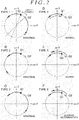
- the first arithmetic circuit 51 and the second arithmetic circuit 52 have the same configuration. However, the first arithmetic circuit 51 and the second arithmetic circuit 52 involve a variation factor associated with hardware characteristics representing individual differences. Consequently, in an orthogonal coordinate system of cos ⁇ and sin ⁇ , a difference ⁇ occurs between the coordinate Q1 plotted by the first arithmetic circuit 51 and the coordinate Q2 plotted by the second arithmetic circuit 52, as depicted in a graph A in FIG. 2 . In the preconditions, the difference ⁇ falls within the range of one quadrant (90°) in the orthogonal coordinate system.
- Occurrence of the difference ⁇ is not abnormal. Thus, determining the presence of an abnormality based on the difference ⁇ needs to be avoided. Therefore, in the present embodiment, in order to accept the difference ⁇ between the two coordinates Q1 and Q2 resulting from the variation factor associated with the hardware characteristics of the first arithmetic circuit 51 and the second arithmetic circuit 52, a shift of up to one quadrant between the coordinates Q1 and Q2 is determined to fall within a normal range.
- the first arithmetic circuit 51 the number of rotations N1
- the count value in the second arithmetic circuit 52 the number of rotations N2
- the first arithmetic circuit 51 and the second arithmetic circuit 52 are each determined to be normal.
- the two coordinates Q1 and Q2 are shifted from each other by two quadrants, the presence of an abnormality is determined.
- the state of a change in the two coordinates Q1 and Q2 is classified into the following six types.
- the abnormality determination circuit 53 determines whether the first arithmetic circuit 51 and the second arithmetic circuit 52 are each abnormal based on these types.
- each of the two coordinates Q1 and Q2 is assumed to initially lie in the first quadrant of the orthogonal coordinate system.
- movement of the coordinate refers to switching of the quadrant where the coordinate Q1 or Q2 is located. This is because movement of the two coordinates Q1 and Q2 is detected (counted) in units of quadrants. Movement of the two coordinates Q1 and Q2 within the same quadrant is determined to have made no movement because the movement involves no switching of the quadrants.
- Type 1 the two coordinates Q1 and Q2 simultaneously move in opposite directions as depicted in the graph A in FIG. 2 .
- the coordinate Q1 moves from the first quadrant to the second quadrant, and at the same time, the coordinate Q2 moves from the first quadrant to the fourth quadrant.
- the abnormality determination circuit 53 immediately determines the presence of an abnormality. This is because the two coordinates Q1 and Q2 are separated from each other by two quadrants.
- Type 2 only a first one of the two coordinates Q1 and Q2 moves in the forward direction or the backward direction, and then, only the first coordinate, having moved, moves further in the same direction as depicted in a graph B in FIG. 2 .
- the coordinate Q1 transitions from the first quadrant to the second quadrant, and then, only the coordinate Q1, having transitioned, transitions further from the second quadrant to the third quadrant.
- the abnormality determination circuit 53 determines the presence of an abnormality. This is because the two coordinates Q1 and Q2 are separated from each other by two quadrants.
- Type 3 only a first one of the two coordinates Q1 and Q2 moves in the forward direction or the backward direction, and then, only a second coordinate moves in a direction opposite to the direction in which the first coordinate has moved, as depicted in a graph C in FIG. 2 .
- the abnormality determination circuit 53 determines the presence of an abnormality. This is because the two coordinates Q1 and Q2 are separated from each other by two quadrants.
- Type 4 only a first one of the two coordinates Q1 and Q2 moves in the forward direction or the backward direction, and then, only the first coordinate, having moved, moves further in a direction opposite to the direction in which the first coordinate has moved, as depicted in a graph D in FIG. 2 .
- the abnormality determination circuit 53 determines the absence of abnormality. This is because one of the coordinates having moved returns to the quadrant where the coordinate was located, so the difference between the quadrants where the two coordinates Q1 and Q2 are located does not increase.
- Type 5 only a first one of the two coordinates Q1 and Q2 moves in the forward direction or the backward direction, and then, only a second coordinate moves in the same direction as the direction in which the first coordinate has moved, as depicted in a graph E in FIG. 2 .
- the abnormality determination circuit 53 determines the absence of abnormality. This is because the relative difference between the quadrants where the two coordinates Q1 and Q2 are located does not increase.
- Type 6 the two coordinates Q1 and Q2 simultaneously move in the same direction as depicted in a graph F in FIG. 2 .
- the two coordinates Q1 and Q2 simultaneously move from the first quadrant to the second quadrant.
- the abnormality determination circuit 53 suspends the determination of whether each of the arithmetic circuits is normal or abnormal until the next sampling time. This is because the determination result may vary depending on a relation with the last movement and the next movement of the two coordinates Q1 and Q2.
- the abnormality determination circuit 53 has determined that the coordinate Q1 moved in the forward direction whereas the coordinate Q2 made no movement (that is, the difference in quadrant is one quadrant), even when the two coordinates Q1 and Q2 simultaneously move in the same direction, the difference between the quadrants where the two coordinates Q1 and Q2 are located is one quadrant and remains unchanged. That is, until the next movement of the two coordinates Q1 and Q2 is checked, it is impossible to determine whether the shift between the two coordinates Q1 and Q2 is equal to two quadrants or a shift of one quadrant is maintained between the coordinates Q1 and Q2 or the coordinates Q1 and Q2 lie in the same quadrant.
- whether the relative positional relationship between the two coordinates Q1 and Q2 involves a shift of two quadrants is determined based on the quadrant transition direction of each of the two coordinates Q1 and Q2 in the orthogonal coordinate system (the direction in which the coordinate transitions from quadrant to quadrant).
- the two coordinates Q1 and Q2 are determined to be in a positional relationship in which the coordinates Q1 and Q2 are relatively shifted by two quadrants, at least one of the first and second arithmetic circuits 51 and 52 is determined to be abnormal.
- Types 1 to 6 appear in a mixed manner over time.
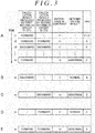
- the following are examples of combinations of the determination result and the rotating directions D1 and D2 of the motor 12 (rotating shaft 12a), that is, the transition directions of the two coordinates Q1 and Q2 in the orthogonal coordinate system.
- each of the two coordinates Q1 and Q2 is determined to have moved in the forward direction.
- This state corresponds to Type 6.
- each of the two coordinates is determined to have moved in the backward direction.
- This state also corresponds to Type 6.
- the state of Type 6 continues, and at a sampling time tn, the coordinate Q1 is determined to have moved in the backward direction, whereas the coordinate Q2 is determined to have made no movement.
- whether the relative positional relationship between the two coordinates Q1 and Q2 is such that the coordinates Q1 and Q2 are shifted from each other by two quadrants can be exhaustively determined based on the rotating direction D1 (the quadrant transition direction of the coordinate Q1) that is a calculation result produced by the first arithmetic circuit 51 and the rotating direction D2 (the quadrant transition direction of the coordinate Q2) that is a calculation result produced by the second arithmetic circuit 52.
- Only one of the first and second arithmetic circuits 51 and 52 may be provided. Now, a configuration in which only the first arithmetic circuit 51 is provided will be discussed as a comparative example.
- the coordinate Q1 plotted on the orthogonal coordinate system transitions from quadrant to quadrant. That is, it is impossible that the coordinate Q1 suddenly transitions two quadrant away (transitions to the quadrant located diagonally with respect to the current quadrant). For example, when the motor 12 rotates forward, the coordinate Q1 located in the first quadrant does not transition directly to the third quadrant rather than to the second quadrant. Thus, the coordinate Q1 transitioning two quadrants away can be determined to be abnormal.
- the expected abnormality is not necessarily limited to the coordinate Q1 transitioning two quadrants away.
- An abnormality is present in which the coordinate Q1 apparently transitions one quadrant as in the case of the normal state. In this case, determining whether each of the arithmetic circuits is normal or abnormal is difficult.
- the first arithmetic circuit 51 may incorrectly recognize that the coordinate Q1 is located in the second quadrant though the coordinate Q1 is actually located in the first quadrant.
- the first arithmetic circuit 51 may incorrectly recognize that the coordinate Q1 is located in the third quadrant though the coordinate Q1 is actually located in the fourth quadrant.
- the coordinate Q1 is actually moving in the forward direction (counterclockwise in the drawings)
- the coordinate Q1 may be incorrectly recognized to be moving in the backward direction (clockwise in the drawings).
- the coordinate Q1 may be incorrectly recognized to be moving in the forward direction though the coordinate Q1 is actually moving in the backward direction.
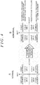
- the first arithmetic circuit 51 incorrectly recognizes that the coordinate Q1 has moved from the third quadrant to the second quadrant. At this time, the first arithmetic circuit 51 incorrectly recognizes that the moving direction of the coordinate Q1 is the backward direction instead of the actual forward direction.
- the first arithmetic circuit 51 incorrectly recognizes that the coordinate Q1 has moved from the second quadrant to the third quadrant. At this time, the first arithmetic circuit 51 incorrectly recognizes that the moving direction of the coordinate Q1 is the forward direction instead of the actual backward direction.
- the first arithmetic circuit 51 and the second arithmetic circuit 52 are provided to allow comparison of the two rotating directions D1 and D2 calculated by the first arithmetic circuit 51 and the second arithmetic circuit 52, respectively. This enables detection of an abnormality in which the coordinate Q1 apparently moves one quadrant as in the case of the normal state. This will be specifically described below.
- the abnormality illustrated in the graph B in FIG. 4 occurs in the first arithmetic circuit 51.
- the second arithmetic circuit 52 is normal, and the normal moving direction of each of the two coordinates Q1 and Q2 is the forward direction (counterclockwise in the drawings).
- the first arithmetic circuit 51 incorrectly recognizes that the coordinate Q1 has moved from the third quadrant to the second quadrant. That is, the first arithmetic circuit 51 incorrectly recognizes that the moving direction of the coordinate Q1 is the backward direction (clockwise in the drawings).
- the second arithmetic circuit 52 correctly recognizes that the coordinate Q2 has moved from the fourth quadrant to the first quadrant. That is, at this time, the second arithmetic circuit 52 correctly recognizes that the moving direction of the coordinate Q2 is the forward direction (clockwise in the drawings).
- the abnormality determination circuit 53 determines at a particular sampling time that the coordinate Q1 has moved in the backward direction, whereas the coordinate Q2 has moved in the forward direction, as described above, the relative positional relationship between the two coordinates Q1 and Q2 is such that the coordinates Q1 and Q2 are shifted from each other by two quadrants. That is, simultaneous detection of these states corresponds to the above-described Type 1 and can be determined to indicate abnormality. Detection of the states at different times corresponds to the above-described Type 3 and can be determined to indicate abnormality.
- the MPU 22 When the power switch 33 in the on state is turned off, the MPU 22 generates a reset signal for the first arithmetic circuit 51 and the second arithmetic circuit 52.
- the first arithmetic circuit 51 and the second arithmetic circuit 52 reset the respective count values to zero based on the reset signal generated by the MPU 22.
- the resetting is performed to allow counting of the numbers of rotations N1 and N2 during a period from turn-off of the power switch 33 until the next turn-on of the power switch 33.
- the MPU 22 turns off the power relay 36 after generating the reset signal.
- the MPU 22 When the power switch 33 in the off state is turned on, the MPU 22 generates an information request signal that requests information from the first arithmetic circuit 51, the second arithmetic circuit 52, and the abnormality determination circuit 53. Based on the information request signal generated by the MPU 22, the first arithmetic circuit 51, the second arithmetic circuit 52, and the abnormality determination circuit 53 provide the number of rotations N1, the number of rotations N2, and the determination result, respectively, to the MPU 22 as the requested information.
- the MPU 22 calculates the steering angle (absolute angle) using the number of rotations N1 acquired from the first arithmetic circuit 51 or the number of rotations N2 acquired from the second arithmetic circuit 52. Determination of the number of rotations N1 or N2 (count value) made while the power switch 33 is off allows determination of the rotation angle ⁇ from the last turn-off of the power switch 33 until the current turn-on of the power switch 33.
- the MPU 22 adds the rotation angle (change angle) obtained while the power switch 33 is off to the rotation angle ⁇ stored at the time of the last turn-off of the power switch 33 to detect the current rotation angle ⁇ .
- the MPU 22 uses the current rotation angle ⁇ to calculate the steering angle (absolute angle), and uses the steering angle to perform compensation control such as steering return control.
- the MPU 22 does not use the number of rotations N1 acquired from the first arithmetic circuit 51 or the number of rotations N2 acquired from the second arithmetic circuit 52. At this time, the MPU 22 may disable a control function such as steering return control which utilizes the steering angle (absolute angle).
- the MPU 22 uses the number of rotations N1 acquired from the first arithmetic circuit 51 or the number of rotations N2 acquired from the second arithmetic circuit 52.
- the present embodiment allows the following effects to be exerted.
- the MPU 22 when the power switch 33 is turned off, the MPU 22 generates the reset signal for the rotation detector 23 (first and second arithmetic circuits 51 and 52).
- this configuration may be modified as follows.
- the MPU 22 stores, in the storage apparatus, the rotation angle ⁇ and the number of rotations N of the motor 12 obtained immediately before the stoppage of the power supply.
- the MPU 22 acquires the number of rotations N (N1 and N2) again through the rotation detector 23.
- the MPU 22 calculates the difference between the number of rotations N obtained when the power switch 33 is turned off and the number of rotations N obtained when the power switch 33 is turned on. Then, the MPU 22 calculates the absolute value of the rotation angle ⁇ and thus the steering angle (absolute angle), taking the calculated difference into account.
- the MR sensor is used as the rotation angle sensor 13.
- a Hall sensor Hall IC
- Any magnetic sensor may be used as long as the magnetic sensor generates two sine signals with different phases and two cosine signals with different phases in association with rotation of the rotating shaft 12a.
- the MPU 22 has the function to calculate the rotation angle ⁇ .
- the rotation detector 23 may have the function to calculate the rotation angle ⁇ (third arithmetic circuit).
- the MPU 22 controls driving of the motor 12 by utilizing the rotation angle ⁇ calculated by the third arithmetic circuit of the rotation detector 23.
Landscapes
- Engineering & Computer Science (AREA)
- Physics & Mathematics (AREA)
- General Physics & Mathematics (AREA)
- Chemical & Material Sciences (AREA)
- Combustion & Propulsion (AREA)
- Transportation (AREA)
- Mechanical Engineering (AREA)
- Power Steering Mechanism (AREA)
- Steering Control In Accordance With Driving Conditions (AREA)
- Measurement Of Length, Angles, Or The Like Using Electric Or Magnetic Means (AREA)
- Transmission And Conversion Of Sensor Element Output (AREA)
Claims (5)
- Appareil de détection de rotation (10) conçu pour détecter une direction de rotation d'un arbre rotatif (12a) et un nombre de rotations de l'arbre rotatif sur la base de premier et deuxième signaux sinusoïdaux et de premier et deuxième signaux cosinusoïdaux générés par un capteur (13) connecté à l'appareil de détection de rotation (10), les premier et deuxième signaux sinusoïdaux étant fonction de la rotation de l'arbre rotatif et ayant des phases décalées l'une de l'autre de 180°, les premier et deuxième signaux cosinusoïdaux étant fonction de la rotation de l'arbre rotatif et ayant des phases décalées l'une de l'autre de 180°, l'appareil de détection de rotation comprenant :un premier circuit arithmétique (51) conçu pour calculer la direction de rotation de l'arbre rotatif et le nombre de rotations de l'arbre rotatif sur la base d'un changement dans une combinaison de positivité et de négativité de valeurs pour le premier signal sinusoïdal et le premier signal cosinusoïdal;un deuxième circuit arithmétique (52) conçu pour calculer la direction de rotation de l'arbre rotatif et le nombre de rotations de l'arbre rotatif sur la base d'un changement dans une combinaison de positivité et de négativité de valeurs pour le deuxième signal sinusoïdal et le deuxième signal cosinusoïdal ; etun circuit de détermination d'anomalie (53) conçu pour déterminer qu'une anomalie est apparue dans au moins l'un des premier et deuxième circuits arithmétiques sur la base de la direction de rotation calculée par le premier circuit arithmétique et de la direction de rotation calculée par le deuxième circuit arithmétique.
- Appareil de détection de rotation selon la revendication 1, dans lequel
le changement dans la combinaison de positivité et de négativité signifie que, dans un système de coordonnées orthogonales dans lequel l'un des signaux sinusoïdaux représente une valeur sur un axe Y et dans lequel le signal cosinusoïdal avec un déphasage de 90° par rapport à la phase du signal sinusoïdal représente une valeur sur un axe X, un quadrant est commuté pour amener les coordonnées à transiter,
dans une condition préalable, un décalage d'un quadrant ou moins est présent entre une première coordonnée qui est un ensemble du premier signal sinusoïdal et du premier signal cosinusoïdal et une deuxième coordonnée qui est un ensemble du deuxième signal sinusoïdal et du deuxième signal cosinusoïdal, du fait d'une différence individuelle entre le premier circuit arithmétique et le deuxième circuit arithmétique,
la direction de rotation calculée par le premier circuit arithmétique correspond à une direction de transition de quadrant de la première coordonnée, et la direction de rotation calculée par le deuxième circuit arithmétique correspond à une direction de transition de quadrant de la deuxième coordonnée, et
le circuit de détermination d'anomalie est conçu pour déterminer qu'au moins l'un des premier et deuxième circuits arithmétiques est anormal, lors de la détermination, sur la base de la direction de transition de quadrant de la première coordonnée et de la direction de transition de quadrant de la deuxième coordonnée, qu'une différence entre un quadrant où la première coordonnée est située et un quadrant où la deuxième coordonnée est située a atteint deux quadrants. - Appareil de détection d'angle de rotation comprenant :l'appareil de détection de rotation selon la revendication 1 ou 2 ; etun circuit de commande conçu pour calculer un angle de rotation de l'arbre rotatif sur la base des premier et deuxième signaux sinusoïdaux et des premier et deuxième signaux cosinusoïdaux générés par le capteur, du nombre de rotations calculé par le premier circuit arithmétique, et du nombre de rotations calculé par le deuxième circuit arithmétique.
- Système de direction à assistance électrique comprenant :l'appareil de détection de rotation selon la revendication 1 ou 2 ;un moteur conçu pour exercer une force d'assistance au braquage dans un véhicule par l'intermédiaire de l'arbre rotatif ; etun circuit de commande conçu pour calculer un angle de rotation de l'arbre rotatif sur la base des premier et deuxième signaux sinusoïdaux et des premier et deuxième signaux cosinusoïdaux générés par le capteur, du nombre de rotations calculé par le premier circuit arithmétique, et du nombre de rotations calculé par le deuxième circuit arithmétique, dans lequelle circuit de commande conçu pour contrôler la commande du moteur sur la base d'un couple de braquage et de l'angle de rotation.
- Système de direction à assistance électrique selon la revendication 4, comprenant en outre une batterie conçue pour continuer d'alimenter le capteur et l'appareil de détection de rotation lorsqu'un commutateur d'alimentation sur le véhicule est ouvert et que l'alimentation du circuit de commande est coupée.
Applications Claiming Priority (1)
| Application Number | Priority Date | Filing Date | Title |
|---|---|---|---|
| JP2015073246A JP6657584B2 (ja) | 2015-03-31 | 2015-03-31 | 回転検出装置、回転角検出装置および電動パワーステアリング装置 |
Publications (2)
| Publication Number | Publication Date |
|---|---|
| EP3076135A1 EP3076135A1 (fr) | 2016-10-05 |
| EP3076135B1 true EP3076135B1 (fr) | 2018-01-24 |
Family
ID=55646371
Family Applications (1)
| Application Number | Title | Priority Date | Filing Date |
|---|---|---|---|
| EP16162600.7A Active EP3076135B1 (fr) | 2015-03-31 | 2016-03-29 | Appareil de détection de rotation, appareil de détection d'angle de rotation et système électrique de direction assistée |
Country Status (4)
| Country | Link |
|---|---|
| US (1) | US9821839B2 (fr) |
| EP (1) | EP3076135B1 (fr) |
| JP (1) | JP6657584B2 (fr) |
| CN (1) | CN106018868B (fr) |
Families Citing this family (29)
| Publication number | Priority date | Publication date | Assignee | Title |
|---|---|---|---|---|
| US10328972B2 (en) * | 2016-04-06 | 2019-06-25 | Denso Corporation | Rotation detecting apparatus and electric power steering apparatus using the same |
| JP6926504B2 (ja) * | 2017-02-10 | 2021-08-25 | 株式会社デンソー | 回転検出装置 |
| JP6760192B2 (ja) * | 2017-04-18 | 2020-09-23 | 株式会社デンソー | 舵角検出装置 |
| DE102017112975B3 (de) * | 2017-06-13 | 2018-10-25 | KNF Micro AG | Membranpumpe |
| JP6787260B2 (ja) * | 2017-06-14 | 2020-11-18 | 株式会社デンソー | ポジションセンサ |
| DE102017116764A1 (de) * | 2017-07-25 | 2019-01-31 | Danfoss Power Solutions Aps | Lenkhandrad-Winkelsensor und Verfahren zur Fehlererfassunq eines Lenkhandrad-Winkelsensors |
| JP6796573B2 (ja) * | 2017-11-17 | 2020-12-09 | 日本電産モビリティ株式会社 | 磁極方向検出装置 |
| US11529990B2 (en) * | 2018-03-20 | 2022-12-20 | Denso Corporation | Signal control apparatus and electric power steering apparatus using same |
| JP7458144B2 (ja) * | 2018-06-08 | 2024-03-29 | 株式会社ジェイテクト | 角度演算装置 |
| JP7225567B2 (ja) * | 2018-05-22 | 2023-02-21 | 株式会社ジェイテクト | 角度演算装置 |
| JP2019196971A (ja) * | 2018-05-09 | 2019-11-14 | 株式会社ジェイテクト | 角度演算装置 |
| US20190346287A1 (en) | 2018-05-09 | 2019-11-14 | Jtekt Corporation | Angle computing device and computing device |
| JP7155602B2 (ja) * | 2018-05-17 | 2022-10-19 | 株式会社ジェイテクト | 演算装置 |
| JP7102923B2 (ja) * | 2018-05-15 | 2022-07-20 | 株式会社ジェイテクト | 車両用制御装置 |
| JP7056367B2 (ja) * | 2018-05-17 | 2022-04-19 | トヨタ自動車株式会社 | 認識エラー検出装置、電動ブレーキ制御装置 |
| JP7255095B2 (ja) * | 2018-05-30 | 2023-04-11 | 株式会社デンソー | 回転検出装置、および、これを用いた電動パワーステアリング装置 |
| JP7172140B2 (ja) * | 2018-05-30 | 2022-11-16 | 株式会社デンソー | 回転検出装置、および、これを用いた電動パワーステアリング装置 |
| JP2020076387A (ja) * | 2018-11-09 | 2020-05-21 | 日本電産トーソク株式会社 | 電動オイルポンプ |
| JP6854841B2 (ja) * | 2019-04-19 | 2021-04-07 | 三菱電機株式会社 | 角度検出装置 |
| JP7256451B2 (ja) * | 2019-05-15 | 2023-04-12 | 株式会社ジェイテクト | モータ制御装置 |
| JP7324060B2 (ja) * | 2019-06-11 | 2023-08-09 | ファナック株式会社 | 位置検出装置 |
| EP3919871B1 (fr) * | 2020-04-08 | 2023-01-11 | NSK Ltd. | Dispositif de détection d'angle de rotation, dispositif de direction assistée électrique, et procédé de commande de dispositif de direction assistée électrique |
| US11608109B2 (en) * | 2020-08-12 | 2023-03-21 | Analog Devices International Unlimited Company | Systems and methods for detecting magnetic turn counter errors with redundancy |
| US11493362B2 (en) | 2020-08-12 | 2022-11-08 | Analog Devices International Unlimited Company | Systems and methods for detecting magnetic turn counter errors |
| JP7284923B2 (ja) * | 2021-04-09 | 2023-06-01 | 株式会社安川電機 | エンコーダ、サーボモータ、サーボシステム |
| CN113548111B (zh) * | 2021-08-16 | 2022-04-26 | 合肥工业大学 | 一种履带式车辆的方向盘转向判断与转角计算方法 |
| JP7572471B2 (ja) * | 2023-01-26 | 2024-10-23 | オリエンタルモーター株式会社 | 多回転角度検出装置およびそのためのセグメントカウンタ |
| CN120092167B (zh) * | 2022-10-25 | 2025-11-04 | 东方马达株式会社 | 多次旋转角度检测装置及用于该装置的分段计数器 |
| CN116794343A (zh) * | 2023-06-09 | 2023-09-22 | 秦皇岛燕大滨沅科技发展有限公司 | 皮带速度检测方法 |
Family Cites Families (15)
| Publication number | Priority date | Publication date | Assignee | Title |
|---|---|---|---|---|
| IT1223863B (it) * | 1988-10-24 | 1990-09-29 | Comau Spa | Dispositivo per determinare e rilevare la posizione raggiunta da un organo mobile particolarmente per il controllo di automi industriali |
| MY120887A (en) * | 1995-06-08 | 2005-12-30 | Sony Corp | Rotation position detecting device and motor device. |
| US6556005B1 (en) * | 2000-01-27 | 2003-04-29 | Goodrich Avionics Systems, Inc. | Magnetic encoder apparatus capable of resolving axial and rotational displacements |
| JP2006335252A (ja) * | 2005-06-02 | 2006-12-14 | Jtekt Corp | 電動パワーステアリング装置 |
| JP2008122216A (ja) * | 2006-11-13 | 2008-05-29 | Tamagawa Seiki Co Ltd | R/d変換機能の異常検出装置 |
| JP2008298745A (ja) * | 2007-06-04 | 2008-12-11 | Tamagawa Seiki Co Ltd | レゾルバを用いた回転検出装置 |
| WO2009060329A1 (fr) * | 2007-11-05 | 2009-05-14 | Nxp B.V. | Convertisseur angulaire/numérique |
| DE102008054973A1 (de) * | 2008-12-19 | 2010-07-01 | Dr. Johannes Heidenhain Gmbh | Umdrehungszähler und Verfahren zum Feststellen der Umdrehungszahl einer Welle |
| JP5315212B2 (ja) | 2009-10-29 | 2013-10-16 | 日立オートモティブシステムズ株式会社 | 回転角度センサ異常検出装置、モータ制御システム、電動パワーステアリング |
| DE102011083042A1 (de) * | 2010-11-29 | 2012-05-31 | Dr. Johannes Heidenhain Gmbh | Überwachungseinheit und Verfahren zur Überwachung von Positionssignalen inkrementaler Positionsmesseinrichtungen |
| JP5389101B2 (ja) * | 2011-04-26 | 2014-01-15 | 三菱電機株式会社 | モータ制御装置 |
| JP6086205B2 (ja) * | 2012-12-12 | 2017-03-01 | 株式会社ジェイテクト | 位相差検出装置およびそれを備えた回転角検出装置 |
| DE102013104586B4 (de) | 2013-05-06 | 2016-09-15 | Robert Bosch Automotive Steering Gmbh | Verfahren zu fortlaufenden Bestimmung eines Lenkwinkels oder einer den Lenkwinkel charakterisierenden Größe |
| JP2014234072A (ja) * | 2013-06-03 | 2014-12-15 | 株式会社ジェイテクト | 電動パワーステアリング装置 |
| JP2015040708A (ja) * | 2013-08-20 | 2015-03-02 | 株式会社ジェイテクト | 回転角センサおよび回転角検出装置 |
-
2015
- 2015-03-31 JP JP2015073246A patent/JP6657584B2/ja active Active
-
2016
- 2016-03-29 US US15/083,920 patent/US9821839B2/en active Active
- 2016-03-29 CN CN201610186603.4A patent/CN106018868B/zh active Active
- 2016-03-29 EP EP16162600.7A patent/EP3076135B1/fr active Active
Non-Patent Citations (1)
| Title |
|---|
| None * |
Also Published As
| Publication number | Publication date |
|---|---|
| CN106018868A (zh) | 2016-10-12 |
| US20160288823A1 (en) | 2016-10-06 |
| CN106018868B (zh) | 2019-11-22 |
| JP6657584B2 (ja) | 2020-03-04 |
| JP2016191702A (ja) | 2016-11-10 |
| US9821839B2 (en) | 2017-11-21 |
| EP3076135A1 (fr) | 2016-10-05 |
Similar Documents
| Publication | Publication Date | Title |
|---|---|---|
| EP3076135B1 (fr) | Appareil de détection de rotation, appareil de détection d'angle de rotation et système électrique de direction assistée | |
| JP6083428B2 (ja) | 車両の電動パワーステアリング装置 | |
| EP3613650B1 (fr) | Appareil de commande de véhicule | |
| JP5679136B2 (ja) | 回転角検出装置、および、回転角検出装置を備えた電動パワーステアリング装置 | |
| US10322748B2 (en) | Motor controller and steering device | |
| US8738232B2 (en) | Electronic control apparatus | |
| EP2573523B1 (fr) | Dispositif de détection de déplacement, système de direction de véhicule et moteur | |
| US12072187B2 (en) | Rotation angle detection device | |
| JP6672993B2 (ja) | 操舵制御装置 | |
| JP6580258B2 (ja) | 電子制御装置及びその動作制御方法 | |
| JP5414893B2 (ja) | ブラシレスモータの駆動装置 | |
| JP2004340873A (ja) | 回転角度検出装置及び回転制御装置 | |
| JP2018143085A (ja) | モータを制御するためのシステム及び方法 | |
| JP2020079000A (ja) | 車両制御装置 | |
| JP2018177005A (ja) | 車両制御装置 | |
| US10666172B2 (en) | Motor control device and motor control method | |
| JPH0331722A (ja) | 指示装置の指針の絶対位置の検出方法及び指示装置 | |
| CN113353144A (zh) | 电动助力转向控制装置和控制方法 | |
| JP2020079058A (ja) | 角度演算装置及び転舵装置 |
Legal Events
| Date | Code | Title | Description |
|---|---|---|---|
| PUAI | Public reference made under article 153(3) epc to a published international application that has entered the european phase |
Free format text: ORIGINAL CODE: 0009012 |
|
| AK | Designated contracting states |
Kind code of ref document: A1 Designated state(s): AL AT BE BG CH CY CZ DE DK EE ES FI FR GB GR HR HU IE IS IT LI LT LU LV MC MK MT NL NO PL PT RO RS SE SI SK SM TR |
|
| AX | Request for extension of the european patent |
Extension state: BA ME |
|
| 17P | Request for examination filed |
Effective date: 20170302 |
|
| RBV | Designated contracting states (corrected) |
Designated state(s): AL AT BE BG CH CY CZ DE DK EE ES FI FR GB GR HR HU IE IS IT LI LT LU LV MC MK MT NL NO PL PT RO RS SE SI SK SM TR |
|
| GRAP | Despatch of communication of intention to grant a patent |
Free format text: ORIGINAL CODE: EPIDOSNIGR1 |
|
| INTG | Intention to grant announced |
Effective date: 20170801 |
|
| GRAS | Grant fee paid |
Free format text: ORIGINAL CODE: EPIDOSNIGR3 |
|
| GRAA | (expected) grant |
Free format text: ORIGINAL CODE: 0009210 |
|
| RAP1 | Party data changed (applicant data changed or rights of an application transferred) |
Owner name: JTEKT CORPORATION |
|
| AK | Designated contracting states |
Kind code of ref document: B1 Designated state(s): AL AT BE BG CH CY CZ DE DK EE ES FI FR GB GR HR HU IE IS IT LI LT LU LV MC MK MT NL NO PL PT RO RS SE SI SK SM TR |
|
| REG | Reference to a national code |
Ref country code: GB Ref legal event code: FG4D |
|
| REG | Reference to a national code |
Ref country code: CH Ref legal event code: EP |
|
| REG | Reference to a national code |
Ref country code: AT Ref legal event code: REF Ref document number: 966028 Country of ref document: AT Kind code of ref document: T Effective date: 20180215 |
|
| REG | Reference to a national code |
Ref country code: IE Ref legal event code: FG4D |
|
| REG | Reference to a national code |
Ref country code: FR Ref legal event code: PLFP Year of fee payment: 3 |
|
| REG | Reference to a national code |
Ref country code: DE Ref legal event code: R096 Ref document number: 602016001428 Country of ref document: DE |
|
| REG | Reference to a national code |
Ref country code: NL Ref legal event code: MP Effective date: 20180124 |
|
| REG | Reference to a national code |
Ref country code: LT Ref legal event code: MG4D |
|
| REG | Reference to a national code |
Ref country code: AT Ref legal event code: MK05 Ref document number: 966028 Country of ref document: AT Kind code of ref document: T Effective date: 20180124 |
|
| PG25 | Lapsed in a contracting state [announced via postgrant information from national office to epo] |
Ref country code: NL Free format text: LAPSE BECAUSE OF FAILURE TO SUBMIT A TRANSLATION OF THE DESCRIPTION OR TO PAY THE FEE WITHIN THE PRESCRIBED TIME-LIMIT Effective date: 20180124 |
|
| PG25 | Lapsed in a contracting state [announced via postgrant information from national office to epo] |
Ref country code: CY Free format text: LAPSE BECAUSE OF FAILURE TO SUBMIT A TRANSLATION OF THE DESCRIPTION OR TO PAY THE FEE WITHIN THE PRESCRIBED TIME-LIMIT Effective date: 20180124 Ref country code: LT Free format text: LAPSE BECAUSE OF FAILURE TO SUBMIT A TRANSLATION OF THE DESCRIPTION OR TO PAY THE FEE WITHIN THE PRESCRIBED TIME-LIMIT Effective date: 20180124 Ref country code: FI Free format text: LAPSE BECAUSE OF FAILURE TO SUBMIT A TRANSLATION OF THE DESCRIPTION OR TO PAY THE FEE WITHIN THE PRESCRIBED TIME-LIMIT Effective date: 20180124 Ref country code: ES Free format text: LAPSE BECAUSE OF FAILURE TO SUBMIT A TRANSLATION OF THE DESCRIPTION OR TO PAY THE FEE WITHIN THE PRESCRIBED TIME-LIMIT Effective date: 20180124 Ref country code: NO Free format text: LAPSE BECAUSE OF FAILURE TO SUBMIT A TRANSLATION OF THE DESCRIPTION OR TO PAY THE FEE WITHIN THE PRESCRIBED TIME-LIMIT Effective date: 20180424 Ref country code: HR Free format text: LAPSE BECAUSE OF FAILURE TO SUBMIT A TRANSLATION OF THE DESCRIPTION OR TO PAY THE FEE WITHIN THE PRESCRIBED TIME-LIMIT Effective date: 20180124 |
|
| PG25 | Lapsed in a contracting state [announced via postgrant information from national office to epo] |
Ref country code: SE Free format text: LAPSE BECAUSE OF FAILURE TO SUBMIT A TRANSLATION OF THE DESCRIPTION OR TO PAY THE FEE WITHIN THE PRESCRIBED TIME-LIMIT Effective date: 20180124 Ref country code: RS Free format text: LAPSE BECAUSE OF FAILURE TO SUBMIT A TRANSLATION OF THE DESCRIPTION OR TO PAY THE FEE WITHIN THE PRESCRIBED TIME-LIMIT Effective date: 20180124 Ref country code: LV Free format text: LAPSE BECAUSE OF FAILURE TO SUBMIT A TRANSLATION OF THE DESCRIPTION OR TO PAY THE FEE WITHIN THE PRESCRIBED TIME-LIMIT Effective date: 20180124 Ref country code: BG Free format text: LAPSE BECAUSE OF FAILURE TO SUBMIT A TRANSLATION OF THE DESCRIPTION OR TO PAY THE FEE WITHIN THE PRESCRIBED TIME-LIMIT Effective date: 20180424 Ref country code: AT Free format text: LAPSE BECAUSE OF FAILURE TO SUBMIT A TRANSLATION OF THE DESCRIPTION OR TO PAY THE FEE WITHIN THE PRESCRIBED TIME-LIMIT Effective date: 20180124 Ref country code: IS Free format text: LAPSE BECAUSE OF FAILURE TO SUBMIT A TRANSLATION OF THE DESCRIPTION OR TO PAY THE FEE WITHIN THE PRESCRIBED TIME-LIMIT Effective date: 20180524 Ref country code: GR Free format text: LAPSE BECAUSE OF FAILURE TO SUBMIT A TRANSLATION OF THE DESCRIPTION OR TO PAY THE FEE WITHIN THE PRESCRIBED TIME-LIMIT Effective date: 20180425 Ref country code: PL Free format text: LAPSE BECAUSE OF FAILURE TO SUBMIT A TRANSLATION OF THE DESCRIPTION OR TO PAY THE FEE WITHIN THE PRESCRIBED TIME-LIMIT Effective date: 20180124 |
|
| REG | Reference to a national code |
Ref country code: DE Ref legal event code: R097 Ref document number: 602016001428 Country of ref document: DE |
|
| PG25 | Lapsed in a contracting state [announced via postgrant information from national office to epo] |
Ref country code: AL Free format text: LAPSE BECAUSE OF FAILURE TO SUBMIT A TRANSLATION OF THE DESCRIPTION OR TO PAY THE FEE WITHIN THE PRESCRIBED TIME-LIMIT Effective date: 20180124 Ref country code: RO Free format text: LAPSE BECAUSE OF FAILURE TO SUBMIT A TRANSLATION OF THE DESCRIPTION OR TO PAY THE FEE WITHIN THE PRESCRIBED TIME-LIMIT Effective date: 20180124 Ref country code: IT Free format text: LAPSE BECAUSE OF FAILURE TO SUBMIT A TRANSLATION OF THE DESCRIPTION OR TO PAY THE FEE WITHIN THE PRESCRIBED TIME-LIMIT Effective date: 20180124 Ref country code: EE Free format text: LAPSE BECAUSE OF FAILURE TO SUBMIT A TRANSLATION OF THE DESCRIPTION OR TO PAY THE FEE WITHIN THE PRESCRIBED TIME-LIMIT Effective date: 20180124 |
|
| PG25 | Lapsed in a contracting state [announced via postgrant information from national office to epo] |
Ref country code: SK Free format text: LAPSE BECAUSE OF FAILURE TO SUBMIT A TRANSLATION OF THE DESCRIPTION OR TO PAY THE FEE WITHIN THE PRESCRIBED TIME-LIMIT Effective date: 20180124 Ref country code: SM Free format text: LAPSE BECAUSE OF FAILURE TO SUBMIT A TRANSLATION OF THE DESCRIPTION OR TO PAY THE FEE WITHIN THE PRESCRIBED TIME-LIMIT Effective date: 20180124 Ref country code: DK Free format text: LAPSE BECAUSE OF FAILURE TO SUBMIT A TRANSLATION OF THE DESCRIPTION OR TO PAY THE FEE WITHIN THE PRESCRIBED TIME-LIMIT Effective date: 20180124 Ref country code: MC Free format text: LAPSE BECAUSE OF FAILURE TO SUBMIT A TRANSLATION OF THE DESCRIPTION OR TO PAY THE FEE WITHIN THE PRESCRIBED TIME-LIMIT Effective date: 20180124 Ref country code: CZ Free format text: LAPSE BECAUSE OF FAILURE TO SUBMIT A TRANSLATION OF THE DESCRIPTION OR TO PAY THE FEE WITHIN THE PRESCRIBED TIME-LIMIT Effective date: 20180124 |
|
| PLBE | No opposition filed within time limit |
Free format text: ORIGINAL CODE: 0009261 |
|
| STAA | Information on the status of an ep patent application or granted ep patent |
Free format text: STATUS: NO OPPOSITION FILED WITHIN TIME LIMIT |
|
| REG | Reference to a national code |
Ref country code: BE Ref legal event code: MM Effective date: 20180331 |
|
| REG | Reference to a national code |
Ref country code: IE Ref legal event code: MM4A |
|
| PG25 | Lapsed in a contracting state [announced via postgrant information from national office to epo] |
Ref country code: LU Free format text: LAPSE BECAUSE OF NON-PAYMENT OF DUE FEES Effective date: 20180329 |
|
| 26N | No opposition filed |
Effective date: 20181025 |
|
| PG25 | Lapsed in a contracting state [announced via postgrant information from national office to epo] |
Ref country code: IE Free format text: LAPSE BECAUSE OF NON-PAYMENT OF DUE FEES Effective date: 20180329 |
|
| PG25 | Lapsed in a contracting state [announced via postgrant information from national office to epo] |
Ref country code: SI Free format text: LAPSE BECAUSE OF FAILURE TO SUBMIT A TRANSLATION OF THE DESCRIPTION OR TO PAY THE FEE WITHIN THE PRESCRIBED TIME-LIMIT Effective date: 20180124 Ref country code: BE Free format text: LAPSE BECAUSE OF NON-PAYMENT OF DUE FEES Effective date: 20180331 |
|
| REG | Reference to a national code |
Ref country code: CH Ref legal event code: PL |
|
| PG25 | Lapsed in a contracting state [announced via postgrant information from national office to epo] |
Ref country code: LI Free format text: LAPSE BECAUSE OF NON-PAYMENT OF DUE FEES Effective date: 20190331 Ref country code: CH Free format text: LAPSE BECAUSE OF NON-PAYMENT OF DUE FEES Effective date: 20190331 Ref country code: MT Free format text: LAPSE BECAUSE OF NON-PAYMENT OF DUE FEES Effective date: 20180329 |
|
| PG25 | Lapsed in a contracting state [announced via postgrant information from national office to epo] |
Ref country code: TR Free format text: LAPSE BECAUSE OF FAILURE TO SUBMIT A TRANSLATION OF THE DESCRIPTION OR TO PAY THE FEE WITHIN THE PRESCRIBED TIME-LIMIT Effective date: 20180124 |
|
| PG25 | Lapsed in a contracting state [announced via postgrant information from national office to epo] |
Ref country code: PT Free format text: LAPSE BECAUSE OF FAILURE TO SUBMIT A TRANSLATION OF THE DESCRIPTION OR TO PAY THE FEE WITHIN THE PRESCRIBED TIME-LIMIT Effective date: 20180124 |
|
| PG25 | Lapsed in a contracting state [announced via postgrant information from national office to epo] |
Ref country code: HU Free format text: LAPSE BECAUSE OF FAILURE TO SUBMIT A TRANSLATION OF THE DESCRIPTION OR TO PAY THE FEE WITHIN THE PRESCRIBED TIME-LIMIT; INVALID AB INITIO Effective date: 20160329 Ref country code: MK Free format text: LAPSE BECAUSE OF NON-PAYMENT OF DUE FEES Effective date: 20180124 |
|
| GBPC | Gb: european patent ceased through non-payment of renewal fee |
Effective date: 20200329 |
|
| PG25 | Lapsed in a contracting state [announced via postgrant information from national office to epo] |
Ref country code: GB Free format text: LAPSE BECAUSE OF NON-PAYMENT OF DUE FEES Effective date: 20200329 |
|
| PGFP | Annual fee paid to national office [announced via postgrant information from national office to epo] |
Ref country code: DE Payment date: 20260204 Year of fee payment: 11 |
|
| PGFP | Annual fee paid to national office [announced via postgrant information from national office to epo] |
Ref country code: FR Payment date: 20260209 Year of fee payment: 11 |