EP3076142B1 - Température de ligne de puissance et système de surveillance sag - Google Patents
Température de ligne de puissance et système de surveillance sag Download PDFInfo
- Publication number
- EP3076142B1 EP3076142B1 EP16168753.8A EP16168753A EP3076142B1 EP 3076142 B1 EP3076142 B1 EP 3076142B1 EP 16168753 A EP16168753 A EP 16168753A EP 3076142 B1 EP3076142 B1 EP 3076142B1
- Authority
- EP
- European Patent Office
- Prior art keywords
- temperature
- conductor
- sag
- tension
- sensor
- Prior art date
- Legal status (The legal status is an assumption and is not a legal conclusion. Google has not performed a legal analysis and makes no representation as to the accuracy of the status listed.)
- Not-in-force
Links
- 239000004020 conductor Substances 0.000 claims description 78
- 230000005540 biological transmission Effects 0.000 claims description 12
- 238000009529 body temperature measurement Methods 0.000 claims description 12
- 238000012544 monitoring process Methods 0.000 claims description 10
- 238000000034 method Methods 0.000 description 14
- 238000005259 measurement Methods 0.000 description 9
- 238000004364 calculation method Methods 0.000 description 5
- 230000007613 environmental effect Effects 0.000 description 4
- 230000033228 biological regulation Effects 0.000 description 3
- 230000007423 decrease Effects 0.000 description 3
- 231100000817 safety factor Toxicity 0.000 description 3
- 238000001816 cooling Methods 0.000 description 2
- 230000002596 correlated effect Effects 0.000 description 2
- 230000003831 deregulation Effects 0.000 description 2
- 238000009434 installation Methods 0.000 description 2
- 238000004458 analytical method Methods 0.000 description 1
- 238000013459 approach Methods 0.000 description 1
- 230000006399 behavior Effects 0.000 description 1
- 238000004422 calculation algorithm Methods 0.000 description 1
- 238000004590 computer program Methods 0.000 description 1
- 230000000875 corresponding effect Effects 0.000 description 1
- 238000005516 engineering process Methods 0.000 description 1
- 239000012212 insulator Substances 0.000 description 1
- 238000012804 iterative process Methods 0.000 description 1
- 238000012417 linear regression Methods 0.000 description 1
- 239000000463 material Substances 0.000 description 1
- 238000000691 measurement method Methods 0.000 description 1
- 238000005457 optimization Methods 0.000 description 1
- 230000005855 radiation Effects 0.000 description 1
- 230000001105 regulatory effect Effects 0.000 description 1
- 230000004044 response Effects 0.000 description 1
- 230000035945 sensitivity Effects 0.000 description 1
- 230000035939 shock Effects 0.000 description 1
- 230000003068 static effect Effects 0.000 description 1
- 239000000725 suspension Substances 0.000 description 1
- 238000012546 transfer Methods 0.000 description 1
- 230000000007 visual effect Effects 0.000 description 1
Images
Classifications
-
- G—PHYSICS
- G01—MEASURING; TESTING
- G01L—MEASURING FORCE, STRESS, TORQUE, WORK, MECHANICAL POWER, MECHANICAL EFFICIENCY, OR FLUID PRESSURE
- G01L5/00—Apparatus for, or methods of, measuring force, work, mechanical power, or torque, specially adapted for specific purposes
- G01L5/04—Apparatus for, or methods of, measuring force, work, mechanical power, or torque, specially adapted for specific purposes for measuring tension in flexible members, e.g. ropes, cables, wires, threads, belts or bands
- G01L5/047—Specific indicating or recording arrangements, e.g. for remote indication, for indicating overload or underload
-
- G—PHYSICS
- G01—MEASURING; TESTING
- G01K—MEASURING TEMPERATURE; MEASURING QUANTITY OF HEAT; THERMALLY-SENSITIVE ELEMENTS NOT OTHERWISE PROVIDED FOR
- G01K11/00—Measuring temperature based upon physical or chemical changes not covered by groups G01K3/00, G01K5/00, G01K7/00 or G01K9/00
-
- G—PHYSICS
- G01—MEASURING; TESTING
- G01C—MEASURING DISTANCES, LEVELS OR BEARINGS; SURVEYING; NAVIGATION; GYROSCOPIC INSTRUMENTS; PHOTOGRAMMETRY OR VIDEOGRAMMETRY
- G01C9/00—Measuring inclination, e.g. by clinometers, by levels
-
- G—PHYSICS
- G01—MEASURING; TESTING
- G01K—MEASURING TEMPERATURE; MEASURING QUANTITY OF HEAT; THERMALLY-SENSITIVE ELEMENTS NOT OTHERWISE PROVIDED FOR
- G01K13/00—Thermometers specially adapted for specific purposes
-
- G—PHYSICS
- G01—MEASURING; TESTING
- G01K—MEASURING TEMPERATURE; MEASURING QUANTITY OF HEAT; THERMALLY-SENSITIVE ELEMENTS NOT OTHERWISE PROVIDED FOR
- G01K3/00—Thermometers giving results other than momentary value of temperature
- G01K3/02—Thermometers giving results other than momentary value of temperature giving means values; giving integrated values
- G01K3/06—Thermometers giving results other than momentary value of temperature giving means values; giving integrated values in respect of space
-
- G—PHYSICS
- G01—MEASURING; TESTING
- G01K—MEASURING TEMPERATURE; MEASURING QUANTITY OF HEAT; THERMALLY-SENSITIVE ELEMENTS NOT OTHERWISE PROVIDED FOR
- G01K7/00—Measuring temperature based on the use of electric or magnetic elements directly sensitive to heat ; Power supply therefor, e.g. using thermoelectric elements
- G01K7/42—Circuits effecting compensation of thermal inertia; Circuits for predicting the stationary value of a temperature
-
- G—PHYSICS
- G01—MEASURING; TESTING
- G01L—MEASURING FORCE, STRESS, TORQUE, WORK, MECHANICAL POWER, MECHANICAL EFFICIENCY, OR FLUID PRESSURE
- G01L5/00—Apparatus for, or methods of, measuring force, work, mechanical power, or torque, specially adapted for specific purposes
- G01L5/04—Apparatus for, or methods of, measuring force, work, mechanical power, or torque, specially adapted for specific purposes for measuring tension in flexible members, e.g. ropes, cables, wires, threads, belts or bands
-
- G—PHYSICS
- G01—MEASURING; TESTING
- G01N—INVESTIGATING OR ANALYSING MATERIALS BY DETERMINING THEIR CHEMICAL OR PHYSICAL PROPERTIES
- G01N3/00—Investigating strength properties of solid materials by application of mechanical stress
-
- H—ELECTRICITY
- H02—GENERATION; CONVERSION OR DISTRIBUTION OF ELECTRIC POWER
- H02G—INSTALLATION OF ELECTRIC CABLES OR LINES, OR OF COMBINED OPTICAL AND ELECTRIC CABLES OR LINES
- H02G7/00—Overhead installations of electric lines or cables
- H02G7/02—Devices for adjusting or maintaining mechanical tension, e.g. take-up device
-
- H—ELECTRICITY
- H02—GENERATION; CONVERSION OR DISTRIBUTION OF ELECTRIC POWER
- H02G—INSTALLATION OF ELECTRIC CABLES OR LINES, OR OF COMBINED OPTICAL AND ELECTRIC CABLES OR LINES
- H02G7/00—Overhead installations of electric lines or cables
- H02G7/05—Suspension arrangements or devices for electric cables or lines
Definitions
- the invention relates to an apparatus for monitoring the average temperature in energized electrical conductors such as power lines so as to assure safe clearance from the ground. More particularly, the invention relates to an apparatus for measuring the temperature and sag of energized electrical conductors such as power lines in real time as they change with varying electrical load on the line as well as varying environmental conditions causing thermal expansion where the temperature monitor assists in the determination of the maximum power transmission feasible through such conductor while maintaining safe clearance from the ground.
- clearance is one of the considerations to electrical utilities because power lines sag under increasing power loads and as a result limitations are placed on the ampacity or maximum load a line is allowed to carry.
- the reason for this is that power lines sag as load is placed on the power line and that sag increases as the load increases.
- This sag-load correlation is the result of heat causing the temperature of the conductor to rise and further causing thermal expansion of the conductor corresponding to load levels. Heat is generated in the conductor by the resistance losses resulting as electrical current flows through it. This heat causes thermal expansion of the conductor. As load increases more heat is generated resulting in ever increasing thermal expansion of the power line causing the power line to sag closer to the ground. Because government regulations mandate the minimum clearance, utilities must assure that this minimum clearance is never violated.
- Adequate clearance regulations are necessary because power lines, after being installed in relation to the ground or structures, may later sag so as to become too close to the ground or structures resulting in significant safety concerns.
- One such concern is that when power lines sag too close to the ground, electrical shock or contact with the lines becomes more feasible and thus safety is at issue.
- Another such concern is that electric flashover scenarios are possible as lines become too close to electrically grounding objects such as the ground or structures, and such electric flashover can result in extensive damage.
- the power lines can be installed such that sufficient clearance is achieved. This can readily be done by mere visual sight alignment or by simple measurement techniques measuring the distance from the lowest part of the line to the ground or nearest structure. It is even possible to very roughly account for factors such as ambient temperature, wind speed, wind direction and other environmental factors using conservative assumptions and historical knowledge. It is noteworthy though that such conservative assumptions result in significantly less than maximum line loading.
- One method for determining power line sag involves measuring the temperature of the conductor at a particular spot on the power line. Mathematical modeling is then used to calculate the sag. This method is an approximation because the conductor temperature varies based upon location radially within the conductor, location on the line, wind, exposure to elements, etc. and thus the approximation may be inaccurate.
- Monitoring sag in a power line by only monitoring temperature can have disadvantages. These disadvantages may include conservative current ratings resulting from an assumed combination of worst case cooling conditions. Worst case cooling condition can include a combination of highest expected ambient temperature and lowest wind speed, both of which may not occur under actual conditions. Monitoring of sag using temperature can also include adding a time function to the calculation that is to intermittently calculate rather than worst case scenario. The actual measurement of conductor sag or alternatively the ground clearance can also be measured manually. These measurements may be done with actual measuring, using acoustics, microwaves, and laser beams, although none of these methods may be practical.
- the equipment can be bulky, heavy and expensive. The equipment is typically installed on the ground under the conductor and thus must be left unattended where it is subject to vandalism, and it reduces the clearance at the center portion of the line where it is installed.
- Another method disclosed in WO2006/014691 A1 includes measuring an angle of inclination from a horizontal line and a surface temperature of the power line. Real-time measurement information is used to perform a two-step iterative process in order to determine the sag of the power line.
- the present invention provides a simplified, accurate and easy to use, time sensitive system of monitoring sag in power transmission lines.
- the invention is a system consisting of temperature sensors and tension sensors that are used in conjunction with an energized electrical conductor to sense average temperature and sag of the suspended conductor in real time and at regular intervals based upon a signal output of the temperature sensor and tension sensor suite. The results can then be used to determine the maximum allowable power transmission while still maintaining safe clearance between the energized electrical conductor and the ground or other obstruction.
- the invention therefore relates to a system for monitoring the average temperature and sag in energized electrical conductors such as power lines so as to assure safe clearance from the ground.
- the invention relates to a system for measuring the temperature of energized electrical conductors such as power lines in real time as it changes with varying electrical load on the line as well as varying environmental conditions causing thermal expansion where the temperature monitor assists in the determination of the maximum power transmission feasible through such conductor while maintaining safe clearance from the ground.
- the invention includes a system consisting of temperature sensors and tension sensors that can be used in conjunction with an energized electrical conductor to sense the average temperature of the suspended conductor in real time and at regular intervals based upon a signal output of the temperature sensor and tension sensor suites. The results may then be used to determine the maximum allowable power transmission while still maintaining safe clearance between the energized electrical conductor and the ground or other obstruction.
- Some of the implementations of the invention can provide one or more of the following advantages:Advantages of the invention include providing an improved methodology for monitoring the average temperature and sag of a conductor to determine the maximum ampacity for power transmission lines.
- a further advantage is to provide such an improved temperature monitor that provides the average conductor temperature which is directly correlated with the sag and having accurate sag measurement so as to allow electric utilities assurances of minimum clearances while also providing maximum load in the lines.
- a further advantage is to provide such an improved temperature monitor, that accounts for all factors affecting the conductor temperature such as ambient temperature, wind speed and direction, solar radiation and any other factors. It is well known that the average conductor temperature incorporating all point temperature measurements along the span is an accurate reflection of all these conditions.
- a further advantage is to provide such an improved sag monitor that provides for the full utilization of power transmission lines.
- a further advantage is to provide such an improved temperature and sag monitor that measures the average temperature and sag of energized electrical conductors in real time as it changes with the electrical load on the line.
- a further advantage is to provide such an improved average temperature and sag monitor that measures the average temperature and sag of energized electrical conductors at regular intervals.
- a further advantage is to provide such an improved average temperature and sag monitor that measures the sag of energized electrical conductors and transmits such information to a receiver for monitoring and/or load adjustment.
- a further advantage is to provide such an improved average temperature and sag monitoring system to determine sag and thus assure minimum clearance.
- a further advantage is to provide such an improved average temperature and sag monitor that will provide accurate inputs to calculate maximum line capacity in real time.
- a further advantage is to provide such an improved average temperature and sag monitor that transmits inclination average temperature and sag/or clearance information to a remote site where power line load may be controlled.
- a further advantage is to provide such an improved average temperature and sag monitor that is flexible, more accurate, easy to install, and cost effective.
- a further advantage is to provide such an average temperature and sag monitor that incorporates one or more or all of the above advantages and advantages.
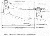
- Figure 1 is a side elevation view of one section of the power lines shown with a sag that provides for sufficient safety clearance between the line and the ground below it.
- a new process for determining the average temperature and sag of a high voltage overhead electrical conductor is described herein.
- the technique uses conductor temperature measurements and tension measurements from overhead line conductors, and incorporates that data into a digital, statistical estimator to derive the average conductor temperature and sag for the entire overhead span.
- the resultant temperature may be further used as in input to a dynamic rating algorithm.
- the catenary equation describes the shape of an overhead electrical wire conductor suspended between two towers and the catenary equation can be used to compute the sag of the conductor relative to the end attachment points and the horizontal component of the tension in the conductor anywhere on the span.
- the catenary equation is provided as Equation 1.
- a catenary is defined as the curve assumed by a hanging flexible wire conductor or chain when supported at its ends and acted upon by a uniform gravitational force.
- ⁇ T w cosh w T ⁇ + C
- y the elevation of the curve above the lowest point of the curve at any point x along the horizontal span of the curve starting at the lowest point
- W is the specific weight per unit length (pounds/foot, for example) of the wire conductor or chain
- T is the horizontal component of the tension (pounds, for example) in the wire or chain.
- the angle of inclination measured by the inclination sensor can be used in conjunction with the catenary equation, and the sag, tension and arc lengths can be readily computed.
- the angle is related by its tangent to the vertical and horizontal tension components in the wire conductor at the (x, y) location along the wire conductor.
- the tension at the point of attachment can be used in conjunction with the catenary equation, instead of the angle of inclination, and the same parameters can be computed.
- said conductor length expands in response to increasing temperature, and as the conductor length increases, the length of the catenary arc increases, the sag increases, and the tension in the conductor decreases.
- the temperature of the conductor can be measured at a point along the conductor by means of a temperature sensor.
- the temperature at a particular point on the conductor is related to the average temperature of the conductor and that the average temperature of the conductor determines the total amount of thermal expansion of the conductor; hence the arc length of the catenary is determined by the average temperature of the conductor.
- the average temperature of the wire conductor can be determined from a mathematical relationship that describes the related behaviors of point temperature measurements "TP" along the power line and angle of inclination measurements "AI", or with the tension in the wire conductor.
- AI can designate either the angle of inclination or tension.
- a relationship can be described by a mathematical formula as embodied in a computer program numerical technique that computes the average temperature of an overhead electrical conductor knowing the weight per unit length of the conductor, horizontal and vertical distances between attachment points, the angle of inclination at a point along the conductor and/or the tension as measured at the end attachment point or on the conductor, and a point temperature along the conductor.
- TPE term should not be confused with the Average Temperature of the conductor as represented by "TA".
- TA TP ⁇ S * AI + AA
- AA is the average angle or average tension, at a measurement point for a specific average conductor temperature.
- the degree of confidence to be placed in these results depends in the accuracy of the measured data.
- VAR X ave X 2 ⁇ ave X 2 COV X
- Y ave X * Y ⁇ ave X * ave Y
- K COV TP , AI 2 VAR TP * VAR AI
- S ⁇ 2 N / N ⁇ 2 * 1 ⁇ K * VAR TP
Landscapes
- Physics & Mathematics (AREA)
- General Physics & Mathematics (AREA)
- Health & Medical Sciences (AREA)
- Life Sciences & Earth Sciences (AREA)
- Chemical & Material Sciences (AREA)
- Analytical Chemistry (AREA)
- Biochemistry (AREA)
- General Health & Medical Sciences (AREA)
- Immunology (AREA)
- Pathology (AREA)
- Engineering & Computer Science (AREA)
- Radar, Positioning & Navigation (AREA)
- Remote Sensing (AREA)
- Electric Cable Installation (AREA)
- Measuring Temperature Or Quantity Of Heat (AREA)
- Suspension Of Electric Lines Or Cables (AREA)
Claims (2)
- Système de surveillance de température et d'affaissement destiné à être utilisé sur une étendue d'un conducteur d'énergie, l'étendue étant une section du conducteur d'énergie suspendue entre une paire de pylônes électriques, le système de surveillance étant destiné à surveiller la température moyenne et l'affaissement de la section lors de la transmission d'énergie, le système de surveillance de température et d'affaissement comprenant :un capteur de température pouvant être positionné sur le conducteur d'énergie, et un capteur de tension produisant des signaux (TP, AI) établissant une corrélation entre la mesure de la température ponctuelle (TP) et la tension (AI) du conducteur ;des émetteurs reliés électriquement au capteur de température et au capteur de tension afin de lire les données de sortie du capteur de température et du capteur de tension et d'émettre des signaux indiquant les données de sortie de capteur (TP, AI) ; etun processeur comprenant un récepteur conçu pour recevoir les signaux indiquant les données de sortie de capteur (TP, AI) du capteur de température et du capteur de tension, caractérisé en ce que :
ledit processeur est conçu pour calculer la corrélation statistique entre les signaux (TP) de capteur de température reçus et les signaux (AI) de capteur de tension reçus et pour calculer la température moyenne de la section du conducteur d'énergie sur la base de ladite corrélation statistique entre les signaux (TP) de capteur de température et les signaux (AI) de capteur de tension, la covariance en temps réel des signaux (TP, AI) du capteur de température et du capteur de tension et la variance en temps réel des signaux (AI) du capteur de tension. - Système de surveillance de température et d'affaissement selon la revendication 1,
le système comprenant en outre un logement conçu pour être monté sur une étendue du conducteur d'énergie, le capteur de température étant fixé à l'intérieur du logement ; et
le capteur de tension étant fixé soit à l'intérieur du logement, soit à l'extérieur du logement, le capteur de tension extérieur étant fixé au niveau d'une extrémité de support du conducteur.
Applications Claiming Priority (3)
| Application Number | Priority Date | Filing Date | Title |
|---|---|---|---|
| US79945306P | 2006-05-11 | 2006-05-11 | |
| EP07761985.6A EP2021753B1 (fr) | 2006-05-11 | 2007-05-08 | Système de surveillance de température et de fléchissement de ligne haute tension |
| PCT/US2007/068429 WO2007134022A2 (fr) | 2006-05-11 | 2007-05-08 | Température de ligne haute tension et système de surveillance sag |
Related Parent Applications (2)
| Application Number | Title | Priority Date | Filing Date |
|---|---|---|---|
| EP07761985.6A Division EP2021753B1 (fr) | 2006-05-11 | 2007-05-08 | Système de surveillance de température et de fléchissement de ligne haute tension |
| EP07761985.6A Division-Into EP2021753B1 (fr) | 2006-05-11 | 2007-05-08 | Système de surveillance de température et de fléchissement de ligne haute tension |
Publications (2)
| Publication Number | Publication Date |
|---|---|
| EP3076142A1 EP3076142A1 (fr) | 2016-10-05 |
| EP3076142B1 true EP3076142B1 (fr) | 2018-07-18 |
Family
ID=38694622
Family Applications (2)
| Application Number | Title | Priority Date | Filing Date |
|---|---|---|---|
| EP16168753.8A Not-in-force EP3076142B1 (fr) | 2006-05-11 | 2007-05-08 | Température de ligne de puissance et système de surveillance sag |
| EP07761985.6A Active EP2021753B1 (fr) | 2006-05-11 | 2007-05-08 | Système de surveillance de température et de fléchissement de ligne haute tension |
Family Applications After (1)
| Application Number | Title | Priority Date | Filing Date |
|---|---|---|---|
| EP07761985.6A Active EP2021753B1 (fr) | 2006-05-11 | 2007-05-08 | Système de surveillance de température et de fléchissement de ligne haute tension |
Country Status (6)
| Country | Link |
|---|---|
| EP (2) | EP3076142B1 (fr) |
| KR (1) | KR101390558B1 (fr) |
| CA (2) | CA2896485C (fr) |
| ES (1) | ES2593927T3 (fr) |
| PL (1) | PL2021753T3 (fr) |
| WO (1) | WO2007134022A2 (fr) |
Families Citing this family (20)
| Publication number | Priority date | Publication date | Assignee | Title |
|---|---|---|---|---|
| US8386198B2 (en) | 2008-11-06 | 2013-02-26 | Southwire Company | Real-time power line rating |
| KR101007503B1 (ko) | 2008-12-03 | 2011-01-12 | 한전케이피에스 주식회사 | 송전선로 이도 측정 방법 |
| EP2425223A4 (fr) * | 2009-04-30 | 2017-01-25 | Underground Systems, Inc. | Dispositif de surveillance de ligne électrique aérienne |
| US10205307B2 (en) | 2010-03-23 | 2019-02-12 | Southwire Company, Llc | Power line maintenance monitoring |
| KR100980389B1 (ko) * | 2010-06-10 | 2010-09-07 | 주식회사 전진이엔지 | 온도변화에 따른 가공배전선의 길이조절 완철 |
| US9647454B2 (en) | 2011-08-31 | 2017-05-09 | Aclara Technologies Llc | Methods and apparatus for determining conditions of power lines |
| EP2815479B1 (fr) * | 2012-02-14 | 2017-01-04 | Tollgrade Communications, Inc. | Methodes et dispositif pour détermininer les conditions d'opération d'une ligne électrique |
| WO2015153539A2 (fr) | 2014-03-31 | 2015-10-08 | Tollgrade Communication, Inc. | Détection de tension optique pour câbles souterrains moyenne tension |
| US10203355B2 (en) | 2014-08-29 | 2019-02-12 | Aclara Technologies Llc | Power extraction for a medium voltage sensor using a capacitive voltage divider |
| CN104596453A (zh) * | 2015-01-20 | 2015-05-06 | 电子科技大学 | 一种测量架空输电线弧垂的系统 |
| SI25126A (sl) * | 2017-04-26 | 2017-07-31 | C & G D.O.O. Ljubljana | Metoda za določitev dodatnih mehanskih obremenitev visokonapetostnega vodnika |
| KR200491175Y1 (ko) * | 2018-10-30 | 2020-05-15 | 이근량 | 버스닥트의 온도와 2채널 기울기 측정 시스템 |
| EP4147022B1 (fr) * | 2020-05-04 | 2025-07-02 | Lindsey Manufacturing Co. | Procédés et systèmes de prédiction de la santé d'un conducteur |
| CN111666690B (zh) * | 2020-06-11 | 2023-10-20 | 海南电网有限责任公司 | 输电线路导线的弧垂分析方法、装置、设备和介质 |
| CN112582958B (zh) * | 2020-12-31 | 2022-10-11 | 国网山东省电力公司龙口市供电公司 | 一种快速调节导线弧垂装置 |
| KR102868194B1 (ko) * | 2024-01-04 | 2025-10-15 | (주)우송전기 | 배전선로의 각 구간 처짐 변화 판단 방법 |
| KR102868195B1 (ko) * | 2024-01-04 | 2025-10-15 | (주)우송전기 | 배전선로의 각 구간 처짐 변화 판단 시스템 |
| CN118189869B (zh) * | 2024-02-28 | 2025-02-18 | 国网江苏省电力有限公司南京供电分公司 | 一种光缆弧垂检测方法、装置、设备及介质 |
| CN118554644B (zh) * | 2024-07-29 | 2024-10-22 | 国网甘肃省电力公司张掖供电公司 | 一种基于远距离电力传输状态监测方法及系统 |
| CN118739619B (zh) * | 2024-09-04 | 2024-11-19 | 上海海能信息科技股份有限公司 | 一种输电线路动态增容监测终端的安装选点方法及系统 |
Family Cites Families (10)
| Publication number | Priority date | Publication date | Assignee | Title |
|---|---|---|---|---|
| US4728887A (en) * | 1984-06-22 | 1988-03-01 | Davis Murray W | System for rating electric power transmission lines and equipment |
| JPH07193986A (ja) * | 1993-12-25 | 1995-07-28 | Sumitomo Electric Ind Ltd | 電力ケーブル接続部の監視方法 |
| US5517864A (en) * | 1994-05-31 | 1996-05-21 | Seppa; Tapani O. | Power transmission line tension monitoring system |
| KR100240747B1 (ko) | 1997-04-26 | 2000-01-15 | 권문구 | 광복합 전력 케이블의 광유니트 삽입형 도체 접속방법 |
| US6097298A (en) * | 1998-02-13 | 2000-08-01 | Ecsi Corporation | Apparatus and method of monitoring a power transmission line |
| US6205867B1 (en) * | 1998-10-07 | 2001-03-27 | American Electric Power, Inc. | Power line sag monitor |
| ATE326073T1 (de) * | 2001-12-21 | 2006-06-15 | Abb Schweiz Ag | Ermittlung der betriebsgrenzwerte in einem energieverteilungsnetz |
| NO318809B1 (no) * | 2002-10-07 | 2005-05-09 | Protura As | Anordning for overvakning av en elektrisk luftstrekk-ledning |
| CA2573858C (fr) * | 2004-07-21 | 2016-09-20 | Underground Systems, Inc. | Systeme dynamique de charge prevue de lignes avec reperage en temps reel de fluage de conducteurs pour l'etablissement d'une charge maximale admissible de conducteur telle que limitee par un degagement |
| US20060265175A1 (en) * | 2005-05-09 | 2006-11-23 | Manuchehr Shimohamadi | Low-cost multi-span conductor temperature measurement system |
-
2007
- 2007-05-08 KR KR1020087030279A patent/KR101390558B1/ko active Active
- 2007-05-08 CA CA2896485A patent/CA2896485C/fr active Active
- 2007-05-08 CA CA2655153A patent/CA2655153C/fr active Active
- 2007-05-08 ES ES07761985.6T patent/ES2593927T3/es active Active
- 2007-05-08 WO PCT/US2007/068429 patent/WO2007134022A2/fr not_active Ceased
- 2007-05-08 EP EP16168753.8A patent/EP3076142B1/fr not_active Not-in-force
- 2007-05-08 EP EP07761985.6A patent/EP2021753B1/fr active Active
- 2007-05-08 PL PL07761985.6T patent/PL2021753T3/pl unknown
Non-Patent Citations (1)
| Title |
|---|
| None * |
Also Published As
| Publication number | Publication date |
|---|---|
| ES2593927T3 (es) | 2016-12-14 |
| KR20090037396A (ko) | 2009-04-15 |
| WO2007134022A2 (fr) | 2007-11-22 |
| EP2021753A4 (fr) | 2015-07-15 |
| WO2007134022A3 (fr) | 2008-01-24 |
| CA2655153C (fr) | 2016-01-19 |
| EP2021753A2 (fr) | 2009-02-11 |
| CA2896485C (fr) | 2019-02-19 |
| CA2655153A1 (fr) | 2007-11-22 |
| EP3076142A1 (fr) | 2016-10-05 |
| KR101390558B1 (ko) | 2014-04-30 |
| CA2896485A1 (fr) | 2007-11-22 |
| EP2021753B1 (fr) | 2016-07-06 |
| PL2021753T3 (pl) | 2016-12-30 |
Similar Documents
| Publication | Publication Date | Title |
|---|---|---|
| EP3076142B1 (fr) | Température de ligne de puissance et système de surveillance sag | |
| US7641387B2 (en) | Power line temperature and sag monitor system | |
| US6523424B1 (en) | Power line sag monitor | |
| US10451770B2 (en) | Method and system for measuring/detecting ice or snow atmospheric accretion on overhead power lines | |
| US5517864A (en) | Power transmission line tension monitoring system | |
| US6097298A (en) | Apparatus and method of monitoring a power transmission line | |
| US7620517B2 (en) | Real-time power-line sag monitoring using time-synchronized power system measurements | |
| US5235861A (en) | Power transmission line monitoring system | |
| CA2573858C (fr) | Systeme dynamique de charge prevue de lignes avec reperage en temps reel de fluage de conducteurs pour l'etablissement d'une charge maximale admissible de conducteur telle que limitee par un degagement | |
| EP3249766B1 (fr) | Procédé et système pour mesurer/détecter l'accrétion atmosphérique de glace ou de neige sur des lignes électriques aériennes | |
| EP3238311B1 (fr) | Procédé et système pour déterminer le coefficient thermique d'une ligne électrique | |
| US20130066600A1 (en) | Method and apparatus for real-time line rating of a transmission line | |
| US20120299603A1 (en) | On-line monitoring system of insulation losses for underground power cables | |
| US5559430A (en) | Net radiation sensor | |
| EP1384084B1 (fr) | Dispositif d'evaluation de lignes aeriennes | |
| RU2165122C2 (ru) | Способ контроля температуры провода воздушной линии электропередачи и устройство для его осуществления | |
| Singh et al. | Feeder dynamic rating application for active distribution network using synchrophasors | |
| Ramachandran et al. | On-line monitoring of sag in overhead transmission lines with leveled spans | |
| McComber et al. | A comparison of selected models for estimating cable icing | |
| US4553092A (en) | Apparatus and method for temperature estimation of overhead conductors | |
| Albizu et al. | Hardware and software architecture for overhead line rating monitoring | |
| CN121783020A (zh) | 基于分布式传感器的输电线路覆冰厚度监测系统 | |
| MX2012007361A (es) | Sistema y metodo para la monitorizacion de ampacidades en lineas electricas aereas. | |
| Ma et al. | Ice monitoring system of transmission lines based on fiber Bragg grating sensor |
Legal Events
| Date | Code | Title | Description |
|---|---|---|---|
| PUAI | Public reference made under article 153(3) epc to a published international application that has entered the european phase |
Free format text: ORIGINAL CODE: 0009012 |
|
| 17P | Request for examination filed |
Effective date: 20160509 |
|
| AC | Divisional application: reference to earlier application |
Ref document number: 2021753 Country of ref document: EP Kind code of ref document: P |
|
| AK | Designated contracting states |
Kind code of ref document: A1 Designated state(s): AT BE BG CH CY CZ DE DK EE ES FI FR GB GR HU IE IS IT LI LT LU LV MC MT NL PL PT RO SE SI SK TR |
|
| GRAP | Despatch of communication of intention to grant a patent |
Free format text: ORIGINAL CODE: EPIDOSNIGR1 |
|
| STAA | Information on the status of an ep patent application or granted ep patent |
Free format text: STATUS: GRANT OF PATENT IS INTENDED |
|
| INTG | Intention to grant announced |
Effective date: 20171212 |
|
| GRAS | Grant fee paid |
Free format text: ORIGINAL CODE: EPIDOSNIGR3 |
|
| GRAA | (expected) grant |
Free format text: ORIGINAL CODE: 0009210 |
|
| STAA | Information on the status of an ep patent application or granted ep patent |
Free format text: STATUS: THE PATENT HAS BEEN GRANTED |
|
| AC | Divisional application: reference to earlier application |
Ref document number: 2021753 Country of ref document: EP Kind code of ref document: P |
|
| AK | Designated contracting states |
Kind code of ref document: B1 Designated state(s): AT BE BG CH CY CZ DE DK EE ES FI FR GB GR HU IE IS IT LI LT LU LV MC MT NL PL PT RO SE SI SK TR |
|
| REG | Reference to a national code |
Ref country code: GB Ref legal event code: FG4D |
|
| REG | Reference to a national code |
Ref country code: CH Ref legal event code: EP |
|
| REG | Reference to a national code |
Ref country code: IE Ref legal event code: FG4D |
|
| REG | Reference to a national code |
Ref country code: AT Ref legal event code: REF Ref document number: 1019887 Country of ref document: AT Kind code of ref document: T Effective date: 20180815 |
|
| REG | Reference to a national code |
Ref country code: DE Ref legal event code: R096 Ref document number: 602007055475 Country of ref document: DE |
|
| RAP2 | Party data changed (patent owner data changed or rights of a patent transferred) |
Owner name: ATECNUM CORPORATION |
|
| REG | Reference to a national code |
Ref country code: NL Ref legal event code: MP Effective date: 20180718 |
|
| RAP2 | Party data changed (patent owner data changed or rights of a patent transferred) |
Owner name: ATECNUM CORPORATION |
|
| REG | Reference to a national code |
Ref country code: LT Ref legal event code: MG4D |
|
| REG | Reference to a national code |
Ref country code: AT Ref legal event code: MK05 Ref document number: 1019887 Country of ref document: AT Kind code of ref document: T Effective date: 20180718 |
|
| PG25 | Lapsed in a contracting state [announced via postgrant information from national office to epo] |
Ref country code: NL Free format text: LAPSE BECAUSE OF FAILURE TO SUBMIT A TRANSLATION OF THE DESCRIPTION OR TO PAY THE FEE WITHIN THE PRESCRIBED TIME-LIMIT Effective date: 20180718 |
|
| PG25 | Lapsed in a contracting state [announced via postgrant information from national office to epo] |
Ref country code: SE Free format text: LAPSE BECAUSE OF FAILURE TO SUBMIT A TRANSLATION OF THE DESCRIPTION OR TO PAY THE FEE WITHIN THE PRESCRIBED TIME-LIMIT Effective date: 20180718 Ref country code: AT Free format text: LAPSE BECAUSE OF FAILURE TO SUBMIT A TRANSLATION OF THE DESCRIPTION OR TO PAY THE FEE WITHIN THE PRESCRIBED TIME-LIMIT Effective date: 20180718 Ref country code: IS Free format text: LAPSE BECAUSE OF FAILURE TO SUBMIT A TRANSLATION OF THE DESCRIPTION OR TO PAY THE FEE WITHIN THE PRESCRIBED TIME-LIMIT Effective date: 20181118 Ref country code: GR Free format text: LAPSE BECAUSE OF FAILURE TO SUBMIT A TRANSLATION OF THE DESCRIPTION OR TO PAY THE FEE WITHIN THE PRESCRIBED TIME-LIMIT Effective date: 20181019 Ref country code: FI Free format text: LAPSE BECAUSE OF FAILURE TO SUBMIT A TRANSLATION OF THE DESCRIPTION OR TO PAY THE FEE WITHIN THE PRESCRIBED TIME-LIMIT Effective date: 20180718 Ref country code: PL Free format text: LAPSE BECAUSE OF FAILURE TO SUBMIT A TRANSLATION OF THE DESCRIPTION OR TO PAY THE FEE WITHIN THE PRESCRIBED TIME-LIMIT Effective date: 20180718 Ref country code: BG Free format text: LAPSE BECAUSE OF FAILURE TO SUBMIT A TRANSLATION OF THE DESCRIPTION OR TO PAY THE FEE WITHIN THE PRESCRIBED TIME-LIMIT Effective date: 20181018 Ref country code: LT Free format text: LAPSE BECAUSE OF FAILURE TO SUBMIT A TRANSLATION OF THE DESCRIPTION OR TO PAY THE FEE WITHIN THE PRESCRIBED TIME-LIMIT Effective date: 20180718 |
|
| PG25 | Lapsed in a contracting state [announced via postgrant information from national office to epo] |
Ref country code: LV Free format text: LAPSE BECAUSE OF FAILURE TO SUBMIT A TRANSLATION OF THE DESCRIPTION OR TO PAY THE FEE WITHIN THE PRESCRIBED TIME-LIMIT Effective date: 20180718 |
|
| REG | Reference to a national code |
Ref country code: DE Ref legal event code: R097 Ref document number: 602007055475 Country of ref document: DE |
|
| PG25 | Lapsed in a contracting state [announced via postgrant information from national office to epo] |
Ref country code: EE Free format text: LAPSE BECAUSE OF FAILURE TO SUBMIT A TRANSLATION OF THE DESCRIPTION OR TO PAY THE FEE WITHIN THE PRESCRIBED TIME-LIMIT Effective date: 20180718 Ref country code: ES Free format text: LAPSE BECAUSE OF FAILURE TO SUBMIT A TRANSLATION OF THE DESCRIPTION OR TO PAY THE FEE WITHIN THE PRESCRIBED TIME-LIMIT Effective date: 20180718 Ref country code: CZ Free format text: LAPSE BECAUSE OF FAILURE TO SUBMIT A TRANSLATION OF THE DESCRIPTION OR TO PAY THE FEE WITHIN THE PRESCRIBED TIME-LIMIT Effective date: 20180718 Ref country code: RO Free format text: LAPSE BECAUSE OF FAILURE TO SUBMIT A TRANSLATION OF THE DESCRIPTION OR TO PAY THE FEE WITHIN THE PRESCRIBED TIME-LIMIT Effective date: 20180718 Ref country code: IT Free format text: LAPSE BECAUSE OF FAILURE TO SUBMIT A TRANSLATION OF THE DESCRIPTION OR TO PAY THE FEE WITHIN THE PRESCRIBED TIME-LIMIT Effective date: 20180718 |
|
| PLBE | No opposition filed within time limit |
Free format text: ORIGINAL CODE: 0009261 |
|
| STAA | Information on the status of an ep patent application or granted ep patent |
Free format text: STATUS: NO OPPOSITION FILED WITHIN TIME LIMIT |
|
| PG25 | Lapsed in a contracting state [announced via postgrant information from national office to epo] |
Ref country code: SK Free format text: LAPSE BECAUSE OF FAILURE TO SUBMIT A TRANSLATION OF THE DESCRIPTION OR TO PAY THE FEE WITHIN THE PRESCRIBED TIME-LIMIT Effective date: 20180718 Ref country code: DK Free format text: LAPSE BECAUSE OF FAILURE TO SUBMIT A TRANSLATION OF THE DESCRIPTION OR TO PAY THE FEE WITHIN THE PRESCRIBED TIME-LIMIT Effective date: 20180718 |
|
| 26N | No opposition filed |
Effective date: 20190423 |
|
| PG25 | Lapsed in a contracting state [announced via postgrant information from national office to epo] |
Ref country code: SI Free format text: LAPSE BECAUSE OF FAILURE TO SUBMIT A TRANSLATION OF THE DESCRIPTION OR TO PAY THE FEE WITHIN THE PRESCRIBED TIME-LIMIT Effective date: 20180718 |
|
| REG | Reference to a national code |
Ref country code: DE Ref legal event code: R119 Ref document number: 602007055475 Country of ref document: DE |
|
| REG | Reference to a national code |
Ref country code: CH Ref legal event code: PL |
|
| GBPC | Gb: european patent ceased through non-payment of renewal fee |
Effective date: 20190508 |
|
| PG25 | Lapsed in a contracting state [announced via postgrant information from national office to epo] |
Ref country code: MC Free format text: LAPSE BECAUSE OF FAILURE TO SUBMIT A TRANSLATION OF THE DESCRIPTION OR TO PAY THE FEE WITHIN THE PRESCRIBED TIME-LIMIT Effective date: 20180718 Ref country code: LI Free format text: LAPSE BECAUSE OF NON-PAYMENT OF DUE FEES Effective date: 20190531 Ref country code: CH Free format text: LAPSE BECAUSE OF NON-PAYMENT OF DUE FEES Effective date: 20190531 |
|
| REG | Reference to a national code |
Ref country code: BE Ref legal event code: MM Effective date: 20190531 |
|
| PG25 | Lapsed in a contracting state [announced via postgrant information from national office to epo] |
Ref country code: LU Free format text: LAPSE BECAUSE OF NON-PAYMENT OF DUE FEES Effective date: 20190508 |
|
| PG25 | Lapsed in a contracting state [announced via postgrant information from national office to epo] |
Ref country code: TR Free format text: LAPSE BECAUSE OF FAILURE TO SUBMIT A TRANSLATION OF THE DESCRIPTION OR TO PAY THE FEE WITHIN THE PRESCRIBED TIME-LIMIT Effective date: 20180718 |
|
| PG25 | Lapsed in a contracting state [announced via postgrant information from national office to epo] |
Ref country code: IE Free format text: LAPSE BECAUSE OF NON-PAYMENT OF DUE FEES Effective date: 20190508 Ref country code: GB Free format text: LAPSE BECAUSE OF NON-PAYMENT OF DUE FEES Effective date: 20190508 Ref country code: DE Free format text: LAPSE BECAUSE OF NON-PAYMENT OF DUE FEES Effective date: 20191203 |
|
| PG25 | Lapsed in a contracting state [announced via postgrant information from national office to epo] |
Ref country code: BE Free format text: LAPSE BECAUSE OF NON-PAYMENT OF DUE FEES Effective date: 20190531 |
|
| PG25 | Lapsed in a contracting state [announced via postgrant information from national office to epo] |
Ref country code: PT Free format text: LAPSE BECAUSE OF FAILURE TO SUBMIT A TRANSLATION OF THE DESCRIPTION OR TO PAY THE FEE WITHIN THE PRESCRIBED TIME-LIMIT Effective date: 20181118 Ref country code: FR Free format text: LAPSE BECAUSE OF NON-PAYMENT OF DUE FEES Effective date: 20190531 |
|
| PG25 | Lapsed in a contracting state [announced via postgrant information from national office to epo] |
Ref country code: CY Free format text: LAPSE BECAUSE OF FAILURE TO SUBMIT A TRANSLATION OF THE DESCRIPTION OR TO PAY THE FEE WITHIN THE PRESCRIBED TIME-LIMIT Effective date: 20180718 |
|
| PG25 | Lapsed in a contracting state [announced via postgrant information from national office to epo] |
Ref country code: HU Free format text: LAPSE BECAUSE OF FAILURE TO SUBMIT A TRANSLATION OF THE DESCRIPTION OR TO PAY THE FEE WITHIN THE PRESCRIBED TIME-LIMIT; INVALID AB INITIO Effective date: 20070508 Ref country code: MT Free format text: LAPSE BECAUSE OF FAILURE TO SUBMIT A TRANSLATION OF THE DESCRIPTION OR TO PAY THE FEE WITHIN THE PRESCRIBED TIME-LIMIT Effective date: 20180718 |