EP3076147B1 - Fluiddetektionsvorrichtung und fluiddetektionsverfahren - Google Patents
Fluiddetektionsvorrichtung und fluiddetektionsverfahren Download PDFInfo
- Publication number
- EP3076147B1 EP3076147B1 EP16158436.2A EP16158436A EP3076147B1 EP 3076147 B1 EP3076147 B1 EP 3076147B1 EP 16158436 A EP16158436 A EP 16158436A EP 3076147 B1 EP3076147 B1 EP 3076147B1
- Authority
- EP
- European Patent Office
- Prior art keywords
- fluid
- detection
- power supply
- regulating apparatus
- condition
- Prior art date
- Legal status (The legal status is an assumption and is not a legal conclusion. Google has not performed a legal analysis and makes no representation as to the accuracy of the status listed.)
- Active
Links
Images

Classifications
-
- F—MECHANICAL ENGINEERING; LIGHTING; HEATING; WEAPONS; BLASTING
- F04—POSITIVE - DISPLACEMENT MACHINES FOR LIQUIDS; PUMPS FOR LIQUIDS OR ELASTIC FLUIDS
- F04B—POSITIVE-DISPLACEMENT MACHINES FOR LIQUIDS; PUMPS
- F04B51/00—Testing machines, pumps, or pumping installations
-
- G—PHYSICS
- G01—MEASURING; TESTING
- G01F—MEASURING VOLUME, VOLUME FLOW, MASS FLOW OR LIQUID LEVEL; METERING BY VOLUME
- G01F23/00—Indicating or measuring liquid level or level of fluent solid material, e.g. indicating in terms of volume or indicating by means of an alarm
- G01F23/22—Indicating or measuring liquid level or level of fluent solid material, e.g. indicating in terms of volume or indicating by means of an alarm by measuring physical variables, other than linear dimensions, pressure or weight, dependent on the level to be measured, e.g. by difference of heat transfer of steam or water
- G01F23/26—Indicating or measuring liquid level or level of fluent solid material, e.g. indicating in terms of volume or indicating by means of an alarm by measuring physical variables, other than linear dimensions, pressure or weight, dependent on the level to be measured, e.g. by difference of heat transfer of steam or water by measuring variations of capacity or inductance of capacitors or inductors arising from the presence of liquid or fluent solid material in the electric or electromagnetic fields
- G01F23/263—Indicating or measuring liquid level or level of fluent solid material, e.g. indicating in terms of volume or indicating by means of an alarm by measuring physical variables, other than linear dimensions, pressure or weight, dependent on the level to be measured, e.g. by difference of heat transfer of steam or water by measuring variations of capacity or inductance of capacitors or inductors arising from the presence of liquid or fluent solid material in the electric or electromagnetic fields by measuring variations in capacitance of capacitors
- G01F23/265—Indicating or measuring liquid level or level of fluent solid material, e.g. indicating in terms of volume or indicating by means of an alarm by measuring physical variables, other than linear dimensions, pressure or weight, dependent on the level to be measured, e.g. by difference of heat transfer of steam or water by measuring variations of capacity or inductance of capacitors or inductors arising from the presence of liquid or fluent solid material in the electric or electromagnetic fields by measuring variations in capacitance of capacitors for discrete levels
-
- G—PHYSICS
- G01—MEASURING; TESTING
- G01M—TESTING STATIC OR DYNAMIC BALANCE OF MACHINES OR STRUCTURES; TESTING OF STRUCTURES OR APPARATUS, NOT OTHERWISE PROVIDED FOR
- G01M3/00—Investigating fluid-tightness of structures
- G01M3/02—Investigating fluid-tightness of structures by using fluid or vacuum
- G01M3/04—Investigating fluid-tightness of structures by using fluid or vacuum by detecting the presence of fluid at the leakage point
-
- G—PHYSICS
- G01—MEASURING; TESTING
- G01M—TESTING STATIC OR DYNAMIC BALANCE OF MACHINES OR STRUCTURES; TESTING OF STRUCTURES OR APPARATUS, NOT OTHERWISE PROVIDED FOR
- G01M3/00—Investigating fluid-tightness of structures
- G01M3/02—Investigating fluid-tightness of structures by using fluid or vacuum
- G01M3/04—Investigating fluid-tightness of structures by using fluid or vacuum by detecting the presence of fluid at the leakage point
- G01M3/16—Investigating fluid-tightness of structures by using fluid or vacuum by detecting the presence of fluid at the leakage point using electric detection means
- G01M3/165—Investigating fluid-tightness of structures by using fluid or vacuum by detecting the presence of fluid at the leakage point using electric detection means by means of cables or similar elongated devices, e.g. tapes
-
- G—PHYSICS
- G01—MEASURING; TESTING
- G01M—TESTING STATIC OR DYNAMIC BALANCE OF MACHINES OR STRUCTURES; TESTING OF STRUCTURES OR APPARATUS, NOT OTHERWISE PROVIDED FOR
- G01M3/00—Investigating fluid-tightness of structures
- G01M3/02—Investigating fluid-tightness of structures by using fluid or vacuum
- G01M3/04—Investigating fluid-tightness of structures by using fluid or vacuum by detecting the presence of fluid at the leakage point
- G01M3/16—Investigating fluid-tightness of structures by using fluid or vacuum by detecting the presence of fluid at the leakage point using electric detection means
- G01M3/18—Investigating fluid-tightness of structures by using fluid or vacuum by detecting the presence of fluid at the leakage point using electric detection means for pipes, cables or tubes; for pipe joints or seals; for valves; for welds; for containers, e.g. radiators
-
- G—PHYSICS
- G01—MEASURING; TESTING
- G01R—MEASURING ELECTRIC VARIABLES; MEASURING MAGNETIC VARIABLES
- G01R31/00—Arrangements for testing electric properties; Arrangements for locating electric faults; Arrangements for electrical testing characterised by what is being tested not provided for elsewhere
- G01R31/40—Testing power supplies
Definitions
- the invention relates to a fluid detection apparatus and a fluid detection method, and more specifically, to a fluid detection apparatus that is able to detect a spread circumstance of a fluid and a fluid detection method.
- a pump is usually utilized to prevent leaking and flooding so that accumulating water is rapidly pumped out of the basement, and thus, property damage is also prevented.
- the pump is generally installed inside a trough-shaped region which is below the ground.
- a water level inside the trough-shaped region increases gradually.
- the pump starts to operate and the water is pumped out of the trough-shaped region through a pipeline. Therefore, the water level inside the trough-shaped region decreases to be within the normal range.
- US 3824460 A discloses an capacitive sensing system adapted for use in detecting the presence of a liquid on a floor or the like in which the sensing probe comprises a pair of encased wires held essentially parallel to each other by a plurality of spaced webs which are an extension of casing of the wires, the probe being held flat on the floor over a considerable length so that leakage anywhere along the probe will result in a capacitance change which may be sensed and an appropriate alarm activated in response thereto.
- WO 2007006747 A1 discloses a method for determining and optionally locating leakage points in pipelines, which are used to transport liquid or gaseous media, by means of at least one electric conductor that runs along the extension of the pipeline from a starting point to an end point. A defined test voltage is applied between two electric conductors and the resistance or impedance behaviour between the starting and end points of the two conductors is determined when the pipeline is intact.
- DE 3539946 A1 discloses a leak-monitoring sensor which has the form of a mat which is constructed as an electrical capacitor whose capacitance value varies in the event of wetting by the liquid to be detected.
- DE 3503800 A1 discloses a device for the measurement of erroneous lines of the junctions with moisture indicators above the junction switches.
- Each junction switch is formed by an electronic switch in the form of a diode or the like and is connected upstream of the moisture indicators which are arranged in the junctions.
- WO 2002082034 A2 discloses a method for detecting the location of faults in a conduit system that is provided with a jacket, at least one wire that runs in a longitudinal direction in relation to the conduit system being located in said jacket at a distance from the conduit system.
- An alternating current is supplied to the conduit system and the wire or the two or more wires which run at a distance from one another, that the magnetic field generated by the alternating current through the conduit system.
- WO 2010046886 A2 discloses a water detector wire for use in a power cable or building, the cable having a wire with a water soluble insulating jacket made of two or more components, wherein a first component has a first solubility in water, and the second component has a second solubility in water, the second solubility being less than the first solubility.
- the present invention is provided by appended device claim 1 and method claim 8. Beneficial embodiments are provided in the dependent claims. Accordingly, the invention provides a fluid detection apparatus and a fluid detection method that could detect an abnormal spread circumstance of a fluid and could issue an alarm immediately to notice the user.
- the fluid detection apparatus of the invention includes a plurality of capacitive detection units and a sensing circuit. Th e capacitive detection units are sequentially arranged along a detection direction, wherein each of the capacitive detection units generates an impedance variation in response to a submergence of a fluid and accordingly generates a corresponding fluid detection signal.
- the sensing circuit is coupled to the capacitive detection units so as to receive the fluid detection signals, and emits a first status indication signal indicating a spread circumstance of the fluid along the detection direction according to the fluid detection signals.
- the fluid detection apparatus further includes a detection carrier.
- the capacitive detection units are sequentially disposed on the detection carrier based on a preset interval.
- the fluid detection apparatus further includes an environment detection unit.
- the environment detection unit is disposed on the detection carrier and coupled to the sensing circuit.
- the environment detection unit is configured to detect an environmental condition and generate an environment detection signal, wherein the sensing circuit in accordance with the environment detection signal emits a second status indication signal indicating that whether the environmental condition exceeds a critical condition.
- the fluid detection apparatus further includes a status alert module.
- the status alert module is coupled to the sensing circuit and configured to decide whether to emit an alarm according to at least one of the first status indication signal and the second status indication signal.
- the fluid detection apparatus further includes a smart power supply.
- the smart power supply is coupled to the sensing circuit.
- the smart power supply is configured to supply power to a fluid regulating apparatus and to detect a power supply condition so as to determine whether the fluid regulating apparatus is in a normal operating condition.
- the smart power supply decides whether to reset so as to restart the fluid regulating apparatus according to the first status indication signal and the power supply condition.
- the smart power supply emits an alarm signal when the smart power supply determines that the fluid regulating apparatus is not in the normal operating condition after reset.
- the smart power supply includes a power supply unit, a relay, a control unit, and a communication unit.
- the power supply unit is configured to supply power to the fluid regulating apparatus.
- the relay is coupled between the power supply unit and the fluid regulating apparatus.
- the relay controls a switching signal to decide whether an operation power is provided to the fluid regulating apparatus.
- the control unit is coupled to the sensing circuit, the fluid regulating apparatus, and the relay.
- the control unit is configured to detect the power supply condition that is provided for the fluid regulating apparatus, and to emit the alarm signal and the switching signal according to the power supply condition and the first status indication signal.
- the communication unit is coupled to the control unit and configured to transmit the alarm signal by the wired or wireless communication method.
- the sensing circuit calculates the time difference of the fluid flowing through two of the capacitive detection units according to the fluid detection signals and generates a third status indication signal of the spread rate of the indicated fluid.
- a fluid detection method of the invention is applied for a fluid detection apparatus, the fluid detection apparatus includes a plurality of capacitive detection units and a sensing circuit.
- the fluid detection method includes the following steps: generating an impedance variation in response to a submergence of a fluid and accordingly generating a corresponding fluid detection signal via each of the capacitive detection units; receiving the fluid detection signals via the sensing circuit; and emitting a first status indication signal indicating a spread circumstance of the fluid along a detection direction according to the fluid detection signals.
- the fluid detection apparatus further includes an environment detection unit
- the fluid detection method further includes the following steps: detecting an environmental condition and generating an environment detection signal via the environment detection unit; receiving the environment detection signal via the sensing circuit; and emitting a second status indication signal indicating whether the environmental condition exceeds a critical condition in accordance with the environment detection signal.
- the fluid detection method further includes the following step: deciding whether to emit an alarm according to at least one of the first status indication signal and the second status indication signal.
- the fluid detection apparatus further includes a smart power supply
- the fluid detection method further includes the following steps: supplying power to a fluid regulating apparatus and receiving the first status indication signal via the smart power supply; detecting a power supply condition of the smart power supply; determining whether the fluid regulating apparatus being in the normal operating condition; and emitting an alarm signal after the smart power supply is reset if the condition that the fluid regulating apparatus is not in the normal operating condition is determined.
- the fluid detection method further includes the following steps: calculating a time difference of the fluid flowing through two of the capacitive detection units via the sensing circuit; and generating the third status indication signal indicating a spread velocity of the fluid according to the time difference.
- the embodiment of the invention provides the fluid detection apparatus including capacitive detection units and the fluid detection method.
- the capacitive detection units are sequentially arranged along a specific detection direction and able to react to the submergence of the fluid, so that the capacitive detection units are able to generate an impedance variation. All the returned fluid detection signals of the capacitive detection units are sensed to achieve the detection of the spread circumstance of the fluid.
- the fluid detection apparatus and the fluid detection method of the embodiments of the invention could further determine punctually and accurately that whether the pump of the fluid regulating apparatus is in the malfunction condition.
- Fig. 1 is a schematic diagram of a fluid detection apparatus of one embodiment of the invention.
- a fluid detection apparatus 100 of this embodiment could detect a fluid condition under a specific environment, for example, a flowing condition and a spreading condition of the fluid.
- the fluid herein means any kinds of gas or liquid, which can be deformed continuously by the shearing stress, have flowability, diffusibility, spreadability, and the deformation may lead the equivalent impedance being varied, such as water or oil.
- the fluid detection apparatus 100 includes a plurality of capacitive detection units 110_1 ⁇ 110_n (n ⁇ 2 and n is an integer and is defined by the designer), a sensing circuit 120, a status alert module 130, and an environment detection unit SDU.
- the capacitive detection units 110_1 ⁇ 110_n are sequentially arranged along a detection direction D (the detection direction D is illustrated as a direction from up to down in the figure).
- Each of the capacitive detection units 110_1 ⁇ 110_n generates an impedance variation in response to a submergence of the fluid and accordingly generates a corresponding fluid detection signal Sfd1 ⁇ Sfdn to provide for the sensing circuit 120.
- the sensing circuit 120 is coupled to the capacitive detection units 110_1 ⁇ 110_n so as to receive the fluid detection signals Sfd1 ⁇ Sfdn. In the present embodiment, the sensing circuit 120 calculates a spread circumstance of the fluid along the detection direction D according to the fluid detection signals Sfd1 ⁇ Sfdn, so as to generate a first status indication signal Ssi1 indicating the spread circumstance of the fluid.
- the status alert module 130 is coupled to the sensing circuit 120 and configured to decide whether to emit an alarm ALM according to the first status indication signal Ssi1 receiving from the sensing circuit 120.
- the alarm ALM could be, for example, light alarm, sound alarm, or any type of warning means that could make the user aware of the occurring condition.
- the environment detection unit SDU is coupled to the sensing circuit 120.
- the environment detection unit SDU is configured to detect an environmental condition (e.g., temperature, humidity, smoke, or any related environmental condition) and generate an environment detection signal Sed.
- the sensing circuit 120 emits a second status indication signal Ssi2, indicating whether the environmental condition exceeds a critical condition, to provide for the status alert module 130 according to the received environment detection signal Sed. Therefore, the status alert module 130 could further decide whether to emit the alarm ALM according to the second status indication signal Ssi2.
- the fluid detection apparatus 100 could be applied in many different situations, such as, it could be installed in a basement, a water tower, a tank of a washing machine, or underground.
- the alarm condition for emitting the alarm ALM can be defined by the user, such that the alarm ALM can be emitted by the fluid detection apparatus 100 when the spread circumstance of the fluid is abnormal.
- the alarm condition can be defined as the alarm ALM is triggered when the fluid spreads to cover three or more of the capacitive detection units 110_1 ⁇ 110_n.
- the sensing circuit 120 determines whether the impedance of three capacitive detection units varies at the same time according to the fluid detection signals Sfd1 ⁇ Sfdn. If the sensing circuit 120 determines that there are three capacitive detection units having impedance variation, it represents that the fluid at least spreads over the intervals covered by 3 capacitive detection units. Therefore, the sensing circuit 120 emits the first status indication signal Ssi1 to the status alert module 130, such that the status alert module 130 emits the alarm ALM such as the flash alarm or the sound alarm according to the first status indication signal Ssi1.
- the user can be noted about the abnormal spread circumstance of the fluid at the environment that the fluid detection apparatus 100 is installed.
- the fluid detection apparatus 100 could not only detect the spread circumstance of the fluid under a specific environment but also detect whether the environmental temperature and/or humidity exceeds a preset value or detect the production of smoke, so as to generate the second status indication signal Ssi2 indicating the environmental condition. Therefore, the back-end circuit may execute the alarm emitting or other warning means to notice the user that there is an abnormal condition in the environment which the fluid detection apparatus 100 is installed.
- the fluid detection apparatus 100 of this embodiment could detect not only the spread circumstance of the fluid under a specific environment but also a spread velocity of the fluid.
- the sensing circuit 120 calculates a time difference of the fluid flowing between two of the capacitive detection units 110_1 ⁇ 110_n according to the fluid detection signals Sfd1 ⁇ Sfdn and generates a third status indication signal Ssi3 indicating the spread velocity of the fluid.
- the sensing circuit 120 could obtain the time points that the fluid submerges/contacts the capacitive detection units 110_1 and 110_2 according to the fluid detection signals Sfdl and Sfd2, and thus calculate the time difference. Therefore , the sensing circuit 120 could calculate the spread velocity of the fluid along the detection direction D according to the interval of the capacitive detection unit 110_1 and 110_2 (defined by the designer) and the time difference.
- both of the aforementioned status alert module 130 and the environment detection unit SDU are optionally configured in the fluid detection apparatus 100.
- the sensing circuit 120 can also emit the first status indication signal Ssi1 to a smart power supply (not shown, but it will be specifically described in the following embodiment), and transmit the alarm signal to the user's electronic devices, such as personal computer or mobile telephone, through the smart power supply by the wired or wireless communication method.
- the capacitive detection units 110_1 ⁇ 110_n could be individually disposed in the fluid detection apparatus 100 without disposing the environment detection unit SDU.
- the configuration of the fluid detection apparatus 100 depends on the design requirement.
- the capacitive detection units 210_1 ⁇ 210_5 is constructed by a plurality of patterned electrodes PE1 ⁇ PE5 formed on detection carrier C (such as substrate).
- the patterned electrodes PE1 ⁇ PE5 are sequentially disposed on the detection carrier C based on a preset interval GP.
- Each of the patterned electrodes PE1 ⁇ PE5 transmits the corresponding fluid detection signal Sfd1 ⁇ Sfd5 to an external cable interface via conductor patterns, and then the fluid detection signals Sfd1 ⁇ Sfd5 are transmitted to the sensing circuit 120 via the cable interface.
- each of the patterned electrodes PE1 ⁇ PE5 has a specific sensing region (shown as dashed box in Fig. 2A ), so as to sense the impedance variation of the corresponding specific region. Therefore, the sensing region of each of the patterned electrodes PE1 ⁇ PE5 is equivalent to each of the capacitive detection unit 210_1 ⁇ 210_5 that is sequentially disposed on the detection carrier C according to the preset interval GP.
- Fig. 2B is a schematic diagram of the configuration of the capacitive detection unit of one embodiment of the invention.
- the capacitive detection units 210_1 ⁇ 210_3 of the embodiment could apply the electrode patterns similar with the electrode patterns shown in Fig. 2A or use another different electrode pattern.
- the difference between the capacitive detection units 210_1 ⁇ 210_5 shown in the present embodiment and the aforementioned embodiment in Fig. 2 is that the environment detection unit SDU is further disposed on the detection carrier C.
- the fluid detection apparatus 100 of the present embodiment can be applied with a fluid regulating apparatus for regulating fluid flow, so as to further detect whether the fluid regulating apparatus is in normal operating condition.
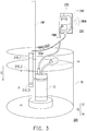
- FIG. 3 is a schematic view of an application environment of a fluid detection apparatus 200 according to the embodiment in Fig. 2B .
- the fluid regulating apparatus in the present embodiment is, for example, a pump 10.
- the fluid detection apparatus 200 is applied for detecting water level in the basement and detecting the function of the pump 10 which is installed in the basement.
- the pump 10 includes a submersible motor 12 and a float switch 14.
- the pump 10 is generally set in a trough-shaped region TR that is located below the ground.
- the fluid detection apparatus 200 of the embodiment includes the capacitive detection units 210_1 ⁇ 210_3 configured on the detection carrier C, the environment detection unit SDU, the sensing circuit 220, the status alert module 230, and the smart power supply 240.
- the sensing circuit 220, the status alert module 230, and the smart power supply 240 are shown as an integrated configuration.
- the detection carrier C could be attached on a pipeline PIP.
- the capacitive detection units 210_1, 210_2, and 210_3 are sequentially configured on the detection carrier C along the detection direction D (the direction from the water surface to inside the water), where the capacitive detection units 210_1, 210_2, and 210_3 are adapted to indicate a high water level condition, a float starting condition, and a low water level condition respectively.
- the configuration and the function of the sensing circuit 220 and the status alert module 230 are similar to the configuration and the function of the sensing circuit 120 and the status alert module 130 in the embodiment described in Fig. 1 , so that detailed descriptions thereof are not repeated.
- the water level inside the trough-shaped region TR increases gradually.
- the float switch 14 is separated from the submersible motor 12.
- the submersible motor 12 comes into operation in response to the separation of the float switch 14, so as to pump out the water inside the trough-shaped region TR and thus decrease the water level of the trough-shaped region TR.
- the submersible motor 12 doesn't start in response to the separation of the float switch 14 so that the pump 10 could't solve the flooding condition punctually, and the user could't be aware of the flooding situation that is happening.
- the sensing circuit 220 could determine that the water level of the trough-shaped region TR raises over the capacitive detection unit 210_1 indicating the high water level condition according to the fluid detection signals Sfd1 ⁇ Sfd3.
- the sensing circuit 220 emits the first status indication signal Ssi1 indicating the high water level condition to the status alert module 230, and thus the status alert module 230 emits the alarm.
- the smart power supply 240 can be applied in the fluid detection apparatus 200 for providing a more accurate detection of the fluid and a faster indication to the user that the abnormal condition happens in the specific detection environment.
- the smart power supply 240 is coupled to the sensing circuit 220.
- the smart power supply 240 is configured to supply power to the pump 10 and detect a power supply condition of the supplied power for determining whether the pump 10 is in a normal operating condition.
- the smart power supply 240 further has the communication function, so as to transmit the alarm signal SALM, via the wired or wireless communication method, to the user's electronic devices to notice the user that the flooding condition could be happening in the basement.
- the sensing circuit 220 emits the corresponding first status indication signal Ssi1 to the smart power supply 240.
- the smart power supply 240 receives the first status indication signal Ssi1 indicating water level reaching the starting height H, the smart power supply 240 detects its own power supply condition and determines whether the pump 10 starts to operate.
- the smart power supply 240 could detect the operation power PWR is provided to the pump 10.
- the smart power supply 240 could detect the operation power PWR that is not provided to the pump 10.
- the smart power supply 240 may reset the power supply, and therefore, restart the pump 10.
- the smart power supply 240 determines whether the malfunction of the pump 10 is solved according to power supply condition after reset. If the smart power supply 240 determines that the pump 10 is not in the normal operating condition so, it represents the malfunction of the pump 10 could't be solved. Therefore, the smart power supply 240 may emit an alarm signal SALM to notify the user about the occurring condition.
- the smart power supply 240 may emit the corresponding alarm signal SALM to notice the user based on the second status indication signal Ssi2.
- the smart power supply 240 determines the condition based on the first status indication signal Ssi1 and/or the second status indication signal Ssi2 incorporated with the power supply condition, the abnormal condition can be immediately detected when the water level reaches the starting height H. It is unnecessary for emitting the alarm ALM or the alarm signal SALM waiting until the water level increases to the height of the capacitive detection unit 210_1. Therefore, the immediately fluid detection mechanism can be implemented.
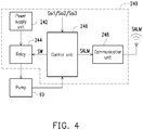
- Fig. 4 is a schematic diagram of a smart power supply of one embodiment of the invention.
- the smart power supply 240 includes a power supply unit 242, a relay 244, a control unit 246, and a communication unit 248.
- the power supply unit 242 is configured to generate an operation power PWR and to supply power to the pump 10.
- the relay 244 is coupled between the power supply unit 242 and the pump 10.
- the relay 244 is controlled by a switching signal SW generated by the control unit 246 and the switching conducting state to decide whether the operation power PWR is provided to the pump 10.
- the control unit 246 is coupled to the sensing circuit 220, the pump 10, and the relay 244.
- the control unit 246 is the control center of the smart power supply 240 and could detect the power supply condition of the operation power PWR provided to the pump 10.
- the control unit 246 is configured to emit the alarm signal SALM and the switching signal SW according to the power supply condition and the first status indication signal Ssc1, the second status indication signal Ssc2 and/or the third status indication signal Ssc3 received from the sensing circuit 220.
- the communication unit 248 is coupled to the control unit 246 and configured to transmit the received alarm signal SALM to the electronic device of the user by the wired or wireless communication method.
- the communication unit 248 could be Wi-Fi module, bluetooth module, and any wire interface or any combination of wire interface.
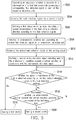
- Fig. 5 is a flow chart of steps of a fluid detection method of one embodiment of the invention.
- the fluid detection method of the present embodiment can be applied for the fluid detection apparatus 100 and 200 that includes a plurality of capacitive detection units (such as 110_1 ⁇ 110_n, 210_1 ⁇ 210_5) and a sensing circuit (such as 120 , 220) as shown in Fig. 1, Fig. 2A, Fig. 2B , and Fig. 3 .
- each of the capacitive detection units generates an impedance variation in response to a submergence of a fluid and accordingly generates a corresponding fluid detection signal (step S502).
- the sensing circuit receives the fluid detection signals (step S504), and emitting a first status indication signal indicating a spread circumstance of the fluid along the detection direction according to the fluid detection signals (step S506).
- the fluid detection method further includes the following steps: the environment detection unit detects an environmental condition and generates an environment detection signal (step S508), and the sensing circuit receives the environment detection signal (step S510) and emits a second status indication signal that whether the environmental condition exceeds a critical condition in accordance with the environment detection signal (step S512).
- the fluid detection method determines whether the spread circumstance of the fluid is abnormal according to the first status indication signal (step S514). If the abnormal spread circumstance of the fluid is determined, the corresponding first alarm is emitted (step S516).
- the fluid detection method further determine whether the environmental condition exceeds the critical condition (step S518) according to the second status indication signal. If the environmental condition exceeding the critical condition is determined, the corresponding second alarm is emitted (step S520).
- step 518 the steps from S510 to S514, step 518, and step 520 in the present embodiment could be optional.
- the detection may not be performed on the environmental condition.
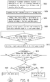
- Fig. 6 is a flow chart of steps of a fluid detection method of one embodiment of the invention.
- the fluid detection method in the present embodiment could apply for the fluid detection apparatus 200 having the smart power supply 240 as shown in Fig. 3 .
- each of the capacitive detection units (such as 210_1 ⁇ 210_3) generates an impedance variation in response to the submergence of the fluid and accordingly generates a corresponding fluid detection signal (step S602).
- the sensing circuit (such as 220) receives the fluid detection signals (step S604), and emits a first status indication signal indicating a spread circumstance of the fluid along the detection direction according to the fluid detection signals (step S606).
- the fluid detection method further includes: the smart power supply (such as 240) powers a fluid regulating apparatus (such as 10) and receives the first status indication signal (step S608).
- the smart power supply determines whether the water level reaches the starting height according to the first status indication signal (step S610).
- the smart power supply detects its own power supply condition (S612) and determines whether the fluid regulating apparatus is in a normal operating condition according to the detected power supply condition (step S614).
- the smart power supply decides (determine) that the fluid regulating apparatus is not in the normal operating condition, the smart power supply further determines that whether it has been reset (step S616). If the reset is not performed, the smart power supply will be commanded to reset (step S618), and return to determine whether the water level reaches the starting height of the step S610. On the contrary, if the malfunction is not solved after reset the smart power supply, the smart power supply will further emit an alarm signal (step S620) to notify the user about the potential leaking and flooding circumstance.
- the embodiment of the invention provides the fluid detection apparatus and the fluid detection method that includes the capacitive detection units.
- the capacitive detection units are sequentially arranged along a specific detection direction and are able to generate impedance variations in response to the submergence of the fluid.
- the detection of the spread circumstance of the fluid can be realized through sensing the fluid detection signals returned by the capacitive detection unit.
- the fluid detection apparatus and the fluid detection method of the embodiments could further immediately and accurately determine that whether the pump of the fluid regulating apparatus is in the malfunction condition.
Landscapes
- Physics & Mathematics (AREA)
- General Physics & Mathematics (AREA)
- Engineering & Computer Science (AREA)
- Power Engineering (AREA)
- Electromagnetism (AREA)
- Thermal Sciences (AREA)
- Fluid Mechanics (AREA)
- Mechanical Engineering (AREA)
- General Engineering & Computer Science (AREA)
- Investigating Or Analyzing Materials By The Use Of Electric Means (AREA)
- Control Of Positive-Displacement Pumps (AREA)
- Indicating Or Recording The Presence, Absence, Or Direction Of Movement (AREA)
Claims (12)
- Fluiderfassungsvorrichtung (100, 200), umfassend eine Vielzahl von kapazitiven Erfassungseinheiten (110_1-110_n, 210_1-210_5), eine Abtastschaltung (120, 220) undeine Fluidregelvorrichtung (10), wobei die kapazitiven Erfassungseinheiten (110_1-110_n, 210_1-210_5) aufeinanderfolgend entlang einer Detektionsrichtung (D) angeordnet sind, wobei die kapazitiven Erfassungseinheiten (110_1-110_n, 210_1-210_5) angepasst sind, um eine Impedanzschwankung zu erzeugen als Reaktion darauf, dass kapazitive Erfassungseinheiten (110_1-110_n, 210_1-210_5) durch ein Fluid getaucht werden und entsprechend angepasst sind, um ein entsprechendes Fluiderfassungssignal (Sfd1-Sfdn) zu erzeugen;wobei die Abtastschaltung (120, 220), die mit den kapazitiven Erfassungseinheiten (110_1-110_n, 210_1-210_5) gekoppelt ist, angepasst ist um die Fluiderfassungssignale (Sfd1-Sfdn) zu empfangen und konfiguriert ist, um ein erstes Statusanzeigesignal (Ssi1) gemäß den Fluiderfassungssignalen (Sfd1-Sfdn) abzugeben; dadurch gekennzeichnet, dassdie Fluidregelvorrichtung (10), die einen Tauchmotor (12) und einen Schwimmerschalter (14) umfasst, angepasst ist, um einen Fluidstrom zu regeln, wobei die Fluidregelvorrichtung (10) in einen muldenförmigen Bereich (TR) gesetzt ist, der sich unter einem Boden befindet, wobei die Fluiderfassungsvorrichtung (100, 200) ferner umfasst:wobei der Stromversorgungszustand anzeigt, ob der Fluidregelvorrichtung (10) ein Betriebsstrom bereitgestellt wird.
eine Stromversorgung (240), die mit der Abtastschaltung (120, 220) gekoppelt ist, wobei die Stromversorgung (240) konfiguriert ist, um die Fluidregelvorrichtung (10) mit Strom zu versorgen und angepasst ist, um einen Stromversorgungszustand zu erfassen, um zu bestimmen, ob die Fluidregelvorrichtung (10) in Betrieb ist, wobei die Stromversorgung (240) konfiguriert ist, um zu entscheiden, ob zurückgesetzt wird, um die Fluidregelvorrichtung (10) gemäß dem ersten Zustandsanzeigesignal (Ssi1) und dem Stromversorgungszustand neu zu starten, - Fluiderfassungsvorrichtung (100, 200) gemäß Anspruch 1, ferner umfassend:
einen Erfassungsträger (C), wobei die kapazitiven Erfassungseinheiten (110_1-110_n, 210_1-210_5) aufeinanderfolgend auf dem Erfassungsträger (C) basierend auf einem vorgegebenen Intervall (GP) angeordnet sind. - Fluiderfassungsvorrichtung (100, 200) gemäß Anspruch 2, ferner umfassend:
eine Umgebungserfassungseinheit (SDU), die auf dem Erfassungsträger (C) angeordnet und mit der Abtastschaltung (120, 220) gekoppelt ist und konfiguriert ist, um einen Umgebungszustand zu erfassen und angepasst ist, um ein Umgebungserfassungssignal (Sed) zu erzeugen, wobei die Abtastschaltung (120, 220) konfiguriert ist, um ein zweites Zustandsanzeigesignal (Ssi2) auszusenden, das anzeigt, ob der Umgebungszustand einen kritischen Zustand überschreitet, gemäß dem Umgebungserfassungssignal (Sed), wobei der Umgebungszustand mindestens eines von Umgebungstemperatur, Luftfeuchtigkeit und Raucherzeugung umfasst. - Fluiderfassungsvorrichtung (100, 200) gemäß Anspruch 3, ferner umfassend:
ein Statusalarmmodul (130, 230), das mit der Abtastschaltung (120, 220) gekoppelt und konfiguriert ist, um zu bestimmen, ob ein Alarm (ALM) gemäß mindestens einem vom dem ersten Statusanzeigesignal (Ssi1) und dem zweiten Statusanzeigesignal (Ssi1) ausgegeben werden soll. - Fluiderfassungsvorrichtung (100, 200) gemäß Anspruch 1, wobei die Stromversorgung (240) konfiguriert ist, um ein Alarmsignal (SALM) abzugeben, wenn die Stromversorgung (240) bestimmt, dass die Fluidregelvorrichtung (10) nicht arbeitet.
- Fluiderfassungsvorrichtung (100, 200) gemäß Anspruch 1, wobei die Stromversorgung (240) umfasst:eine Stromversorgungseinheit (242), die konfiguriert ist, um die Fluidregelvorrichtung (10) mit Strom zu versorgen;ein Relais (244), das zwischen der Stromversorgungseinheit (242) und der Fluidregelvorrichtung (10) gekoppelt ist, wobei das Relais (244) durch ein Schaltsignal (SW) gesteuert wird, um zu entscheiden, ob der Betriebsstrom der Fluidregelvorrichtung (10) zugeführt wird;eine Steuereinheit (246), die mit der Abtastschaltung (120, 220), der Fluidregelvorrichtung (10) und dem Relais (244) gekoppelt ist, wobei die Steuereinheit (246) konfiguriert ist, um den Stromversorgungszustand zu erfassen, der der Fluidregelvorrichtung (10) bereitgestellt wird, und angepasst ist, um das Alarmsignal (SALM) und das Schaltsignal (SW) gemäß dem Stromversorgungszustand und dem ersten Statusanzeigesignal (Ssi1) auszugeben; undeine Kommunikationseinheit (248), die mit der Steuereinheit (246) gekoppelt ist, wobei die Kommunikationseinheit (248) konfiguriert ist, um das Alarmsignal (SALM) durch ein drahtgebundenes oder drahtloses Kommunikationsverfahren zu übertragen.
- Fluiderfassungsvorrichtung (100, 200) gemäß Anspruch 1, wobei die Abtastschaltung (120, 220) konfiguriert ist, um eine Zeitdifferenz des durch zwei der kapazitiven Erfassungseinheiten (110_1-110_n, 210_1-210_5) strömenden Fluids gemäß den Flüssigkeitserfassungssignalen (Sfd1-Sfdn) zu berechnen und ein drittes Statusanzeigesignal (Ssi3) erzeugt, das eine Ausbreitungsgeschwindigkeit des Fluids anzeigt.
- Fluiderfassungsverfahren, das für eine Fluiderfassungsvorrichtung (100, 200) angewendet wird, wobei die Fluiderfassungsvorrichtung (100, 200) eine Vielzahl von kapazitiven Erfassungseinheiten (110_1-110_n, 210_1-210_5), eine Abtastschaltung (120, 220), eine Fluidregelvorrichtung (10) und eine Stromversorgung (240) umfasst, wobei das Fluiderfassungsverfahren umfasst: Erzeugen von Impedanzschwankungen als Reaktion darauf, dass kapazitive Erfassungseinheiten (110_1-110_n, 210_1-210_5) durch ein Fluid getaucht werden und dementsprechend ein entsprechendes Erzeugen eines Fluiderfassungssignals (Sfd1-Sfdn) über die kapazitiven Erfassungseinheiten (110_1-110_n, 210_1-210_5); Empfangen der Fluiderfassungssignale (Sfd1-Sfdn) über die Abtastschaltung (120, 220); und Emittieren eines ersten Zustandsanzeigesignals (Ssi1) gemäß den Flüssigkeitserfassungssignalen (Sfd1-Sfdn); wobei das Verfahren dadurch gekennzeichnet ist, dass es umfasst:
Regeln eines Fluidstroms über die Fluidregelvorrichtung (10), umfassend einen Tauchmotor (12) und einen Schwimmerschalter (14), wobei die Fluidregelvorrichtung (10) in einen muldenförmigen Bereich (TR) gesetzt ist, der sich unter einem Boden befindet, wobei das Verfahren umfasst:Zuführen von Strom zu der Fluidregelvorrichtung (10) und Empfangen des ersten Zustandsanzeigesignals (Ssi1) über die Stromversorgung (240);Erfassen eines Stromversorgungszustands der Stromversorgung (240);Bestimmen, ob die Fluidregelvorrichtung (10) arbeitet, gemäß dem Stromversorgungszustand; undEntscheiden, ob die Stromversorgung (240) zurückgesetzt und die Fluidregelvorrichtung (10) gemäß dem ersten Zustandsanzeigesignal (Ssi1) und dem Zustand der Stromversorgung neu gestartet werden soll,wobei die Stromversorgungsbedingung anzeigt, ob der Fluidregelvorrichtung (10) ein Betriebsstrom bereitgestellt wird. - Fluiderfassungsverfahren gemäß Anspruch 8, wobei die Fluiderfassungsvorrichtung (100, 200) ferner eine Umgebungserfassungseinheit (SDU) umfasst, und das Fluiderfassungsverfahren ferner umfasst:Erfassen eines Umgebungszustands und Erzeugen eines Umgebungserfassungssignals (Sed) über eine Umgebungserfassungseinheit (SDU);Empfangen des Umgebungserfassungssignals (Sed) über die Abtastschaltung (120, 220); undAussenden eines zweiten Zustandsanzeigesignals (Ssi2), das anzeigt, ob der Umgebungszustand einen kritischen Zustand überschreitet, gemäß dem Umgebungserfassungssignal (Sed), wobei der Umgebungszustand mindestens eines von Umgebungstemperatur, Luftfeuchtigkeit und Raucherzeugung umfasst.
- Fluiderfassungsverfahren nach Anspruch 9, ferner umfassend:
Entscheiden, ob ein Alarm (ALM) gemäß mindestens einem von dem ersten Statusanzeigesignal (Ssi1) und dem zweiten Statusanzeigesignal (Ssi2) ausgegeben werden soll. - Fluiderfassungsverfahren gemäß Anspruch 8, ferner umfassend:Bestimmen, ob die Fluidregelvorrichtung (10) arbeitet, gemäß dem Stromversorgungszustand, nachdem die Stromversorgung (240) zurückgesetzt wurde; undAusgeben eines Alarmsignals (SALM), wenn die Fluidregelvorrichtung (10) nach dem Zurücksetzen der Stromversorgung (240) nicht arbeitet.
- Fluiderfassungsverfahren gemäß Anspruch 8, ferner umfassend:Berechnen einer Zeitdifferenz des Fluids, das durch zwei der kapazitiven Erfassungseinheiten (110_1-110_n, 210_1-210_5) strömt, über die Abtastschaltung (120, 220); undErzeugen eines dritten Statusanzeigesignals (Ssi3), das eine Ausbreitungsgeschwindigkeit des Fluids gemäß der Zeitdifferenz anzeigt.
Applications Claiming Priority (1)
| Application Number | Priority Date | Filing Date | Title |
|---|---|---|---|
| TW104110296A TWI546520B (zh) | 2015-03-30 | 2015-03-30 | 流體偵測裝置及流體偵測方法 |
Publications (2)
| Publication Number | Publication Date |
|---|---|
| EP3076147A1 EP3076147A1 (de) | 2016-10-05 |
| EP3076147B1 true EP3076147B1 (de) | 2019-05-08 |
Family
ID=55456655
Family Applications (1)
| Application Number | Title | Priority Date | Filing Date |
|---|---|---|---|
| EP16158436.2A Active EP3076147B1 (de) | 2015-03-30 | 2016-03-03 | Fluiddetektionsvorrichtung und fluiddetektionsverfahren |
Country Status (4)
| Country | Link |
|---|---|
| US (1) | US9695816B2 (de) |
| EP (1) | EP3076147B1 (de) |
| CN (1) | CN106017608B (de) |
| TW (1) | TWI546520B (de) |
Families Citing this family (7)
| Publication number | Priority date | Publication date | Assignee | Title |
|---|---|---|---|---|
| CN111201144A (zh) * | 2017-10-18 | 2020-05-26 | 惠普发展公司,有限责任合伙企业 | 流体特性传感器 |
| US20210129549A1 (en) * | 2017-10-18 | 2021-05-06 | Hewlett-Packard Development Company, L.P. | Fluid property sensor |
| CN113614496A (zh) * | 2019-04-05 | 2021-11-05 | 惠普发展公司,有限责任合伙企业 | 流体特性传感器 |
| JP6916494B1 (ja) * | 2020-04-03 | 2021-08-11 | 三和株式会社 | 漏水検知センサ用構造体及びそれを備えた漏水検知センサ |
| JP7109643B1 (ja) * | 2021-10-20 | 2022-07-29 | 日本航空電子工業株式会社 | 静電容量式水位計 |
| CN114061706B (zh) * | 2021-11-15 | 2024-09-24 | 苏州晶洲装备科技有限公司 | 一种液位检测方法与装置、可读存储介质 |
| CN117189564B (zh) * | 2023-09-20 | 2025-06-06 | 嵊州市铭动电子科技有限公司 | 一种流体检测的水泵控制方法、系统、电子设备及介质 |
Family Cites Families (14)
| Publication number | Priority date | Publication date | Assignee | Title |
|---|---|---|---|---|
| US3824460A (en) * | 1973-04-02 | 1974-07-16 | R Gustafson | Leakage sensor |
| DE3503800A1 (de) | 1985-02-05 | 1986-08-07 | HDW-Elektronik GmbH, 2300 Kiel | Einrichtung zur ermittlung von fehlerhaften abzweigen mit feuchtigkeitsorten in verzweigten rohrleitungsnetzen |
| DE3539946A1 (de) | 1985-11-11 | 1987-05-14 | Gore W L & Co Gmbh | Leckueberwachungssensor |
| US4819483A (en) | 1987-03-26 | 1989-04-11 | Custom Controls Co., Inc. | Level indicator control system for use with capacitance probes in tanks containing substances |
| DE10117238A1 (de) * | 2001-04-06 | 2002-10-17 | Fraunhofer Ges Forschung | Verfahren und Vorrichtung zur Detektion von Fehlerstellen in isolierten Leitungssystemen |
| AT501758B1 (de) * | 2005-07-13 | 2006-11-15 | Bier Guenther Ing | Verfahren zur ortung von leckagen in rohren |
| EP2344853A2 (de) * | 2008-10-24 | 2011-07-20 | Nexans | Feuchtigkeitsdetektionsdraht, feuchtigkeitsdetektionssystem und verfahren zum detektieren von feuchtigkeit |
| CN101476917B (zh) | 2009-01-20 | 2011-03-16 | 江苏工业学院 | 一种可同时检测液位和电导率的传感器 |
| CN101858770B (zh) | 2009-04-09 | 2013-04-24 | 深圳迈瑞生物医疗电子股份有限公司 | 液面检测装置及加样系统 |
| DE102010043083A1 (de) * | 2010-10-28 | 2012-05-03 | Robert Bosch Gmbh | Sensorvorrichtung zur Erfassung einer Strömungseigenschaft eines fluiden Mediums |
| CN202304947U (zh) | 2011-11-03 | 2012-07-04 | 十速科技股份有限公司 | 给皂机液位感测装置 |
| JP6025359B2 (ja) | 2012-03-27 | 2016-11-16 | 三菱重工業株式会社 | 水位計および原子力施設 |
| TWM469480U (zh) | 2013-04-11 | 2014-01-01 | Univ Cheng Shiu | 水位監測系統 |
| CN204212958U (zh) * | 2014-09-18 | 2015-03-18 | 四川达竹煤电(集团)有限责任公司铁山南煤矿 | 矿井排水泵自动控制装置 |
-
2015
- 2015-03-30 TW TW104110296A patent/TWI546520B/zh active
- 2015-06-17 CN CN201510336323.2A patent/CN106017608B/zh active Active
- 2015-07-17 US US14/801,856 patent/US9695816B2/en active Active
-
2016
- 2016-03-03 EP EP16158436.2A patent/EP3076147B1/de active Active
Non-Patent Citations (1)
| Title |
|---|
| None * |
Also Published As
| Publication number | Publication date |
|---|---|
| CN106017608B (zh) | 2020-05-12 |
| US20160290332A1 (en) | 2016-10-06 |
| TWI546520B (zh) | 2016-08-21 |
| EP3076147A1 (de) | 2016-10-05 |
| US9695816B2 (en) | 2017-07-04 |
| CN106017608A (zh) | 2016-10-12 |
| TW201634903A (zh) | 2016-10-01 |
Similar Documents
| Publication | Publication Date | Title |
|---|---|---|
| EP3076147B1 (de) | Fluiddetektionsvorrichtung und fluiddetektionsverfahren | |
| US9212965B2 (en) | Leak detection device and remote monitoring system having slave controllers with unique IDs | |
| US6683535B1 (en) | Water detection system and method | |
| US9823289B2 (en) | Automated digital earth fault system | |
| CN102016531A (zh) | 用于检测水分的泄漏传感器装置 | |
| CN112462190B (zh) | 地下电缆故障探测多足机器人、探测系统及探测方法 | |
| CN103033686B (zh) | 用于具有动态响应特性的绝缘故障监测的方法 | |
| KR102389354B1 (ko) | 지하 차도 침수를 모니터링하고 지하 차도 침수를 미리 경보하는 지하 차도 침수 모니터링 경보 시스템 | |
| JP2008233031A (ja) | 漏水検知システム | |
| US10935508B2 (en) | Liquid detection device and liquid detection system for abnormal liquid on a surface | |
| US20210286383A1 (en) | Liquid handling system monitoring systems and methods | |
| JP2022502650A (ja) | 熱流体検出を有する電子機器ハウジング | |
| EP3273221B1 (de) | System und verfahren zur detektion von korrosion | |
| KR100909241B1 (ko) | 물성감지 리크 센싱 테이프의 제어 장치 및 이를 이용한원격 모니터링 장치 | |
| KR101479177B1 (ko) | 물성감지 리크센서 | |
| KR20180097850A (ko) | 지중케이블 상태 감시 시스템, 장치 및 방법 | |
| KR101610053B1 (ko) | 누수감지센서 | |
| US11193481B2 (en) | Sump pump system and control methodology therefor | |
| CN101191803A (zh) | 过电压检测器和检测过电压的方法 | |
| KR102087562B1 (ko) | 누액센서장치와 누액감지시스템 | |
| CN211236197U (zh) | 一种电连接器故障检测系统 | |
| KR102187189B1 (ko) | 단선 및 리크 검출 장치 및 검출 방법 | |
| EP2975317A1 (de) | Verfahren zur Steuerung einer Heizung und Kommunikation in einem Rohrleitungssystem | |
| KR101256703B1 (ko) | 무선 센싱 장치 및 그 무선 센싱 장치들을 이용한 침수감지 시스템 | |
| KR101321804B1 (ko) | 고주파 대전력 설비 상태감시시스템 |
Legal Events
| Date | Code | Title | Description |
|---|---|---|---|
| PUAI | Public reference made under article 153(3) epc to a published international application that has entered the european phase |
Free format text: ORIGINAL CODE: 0009012 |
|
| AK | Designated contracting states |
Kind code of ref document: A1 Designated state(s): AL AT BE BG CH CY CZ DE DK EE ES FI FR GB GR HR HU IE IS IT LI LT LU LV MC MK MT NL NO PL PT RO RS SE SI SK SM TR |
|
| AX | Request for extension of the european patent |
Extension state: BA ME |
|
| STAA | Information on the status of an ep patent application or granted ep patent |
Free format text: STATUS: REQUEST FOR EXAMINATION WAS MADE |
|
| 17P | Request for examination filed |
Effective date: 20170331 |
|
| RBV | Designated contracting states (corrected) |
Designated state(s): AL AT BE BG CH CY CZ DE DK EE ES FI FR GB GR HR HU IE IS IT LI LT LU LV MC MK MT NL NO PL PT RO RS SE SI SK SM TR |
|
| STAA | Information on the status of an ep patent application or granted ep patent |
Free format text: STATUS: EXAMINATION IS IN PROGRESS |
|
| 17Q | First examination report despatched |
Effective date: 20171002 |
|
| REG | Reference to a national code |
Ref country code: DE Ref legal event code: R079 Ref document number: 602016013424 Country of ref document: DE Free format text: PREVIOUS MAIN CLASS: G01M0003160000 Ipc: F04B0051000000 |
|
| RIC1 | Information provided on ipc code assigned before grant |
Ipc: G01F 23/26 20060101ALI20180830BHEP Ipc: G01R 31/40 20140101ALI20180830BHEP Ipc: G01M 3/04 20060101ALI20180830BHEP Ipc: G01M 3/18 20060101ALI20180830BHEP Ipc: F04B 51/00 20060101AFI20180830BHEP Ipc: G01M 3/16 20060101ALI20180830BHEP |
|
| GRAP | Despatch of communication of intention to grant a patent |
Free format text: ORIGINAL CODE: EPIDOSNIGR1 |
|
| STAA | Information on the status of an ep patent application or granted ep patent |
Free format text: STATUS: GRANT OF PATENT IS INTENDED |
|
| INTG | Intention to grant announced |
Effective date: 20181016 |
|
| GRAS | Grant fee paid |
Free format text: ORIGINAL CODE: EPIDOSNIGR3 |
|
| GRAA | (expected) grant |
Free format text: ORIGINAL CODE: 0009210 |
|
| STAA | Information on the status of an ep patent application or granted ep patent |
Free format text: STATUS: THE PATENT HAS BEEN GRANTED |
|
| AK | Designated contracting states |
Kind code of ref document: B1 Designated state(s): AL AT BE BG CH CY CZ DE DK EE ES FI FR GB GR HR HU IE IS IT LI LT LU LV MC MK MT NL NO PL PT RO RS SE SI SK SM TR |
|
| REG | Reference to a national code |
Ref country code: GB Ref legal event code: FG4D |
|
| REG | Reference to a national code |
Ref country code: CH Ref legal event code: EP Ref country code: AT Ref legal event code: REF Ref document number: 1130539 Country of ref document: AT Kind code of ref document: T Effective date: 20190515 |
|
| REG | Reference to a national code |
Ref country code: DE Ref legal event code: R096 Ref document number: 602016013424 Country of ref document: DE Ref country code: IE Ref legal event code: FG4D |
|
| REG | Reference to a national code |
Ref country code: NL Ref legal event code: MP Effective date: 20190508 |
|
| REG | Reference to a national code |
Ref country code: LT Ref legal event code: MG4D |
|
| PG25 | Lapsed in a contracting state [announced via postgrant information from national office to epo] |
Ref country code: SE Free format text: LAPSE BECAUSE OF FAILURE TO SUBMIT A TRANSLATION OF THE DESCRIPTION OR TO PAY THE FEE WITHIN THE PRESCRIBED TIME-LIMIT Effective date: 20190508 Ref country code: LT Free format text: LAPSE BECAUSE OF FAILURE TO SUBMIT A TRANSLATION OF THE DESCRIPTION OR TO PAY THE FEE WITHIN THE PRESCRIBED TIME-LIMIT Effective date: 20190508 Ref country code: NL Free format text: LAPSE BECAUSE OF FAILURE TO SUBMIT A TRANSLATION OF THE DESCRIPTION OR TO PAY THE FEE WITHIN THE PRESCRIBED TIME-LIMIT Effective date: 20190508 Ref country code: AL Free format text: LAPSE BECAUSE OF FAILURE TO SUBMIT A TRANSLATION OF THE DESCRIPTION OR TO PAY THE FEE WITHIN THE PRESCRIBED TIME-LIMIT Effective date: 20190508 Ref country code: PT Free format text: LAPSE BECAUSE OF FAILURE TO SUBMIT A TRANSLATION OF THE DESCRIPTION OR TO PAY THE FEE WITHIN THE PRESCRIBED TIME-LIMIT Effective date: 20190908 Ref country code: ES Free format text: LAPSE BECAUSE OF FAILURE TO SUBMIT A TRANSLATION OF THE DESCRIPTION OR TO PAY THE FEE WITHIN THE PRESCRIBED TIME-LIMIT Effective date: 20190508 Ref country code: NO Free format text: LAPSE BECAUSE OF FAILURE TO SUBMIT A TRANSLATION OF THE DESCRIPTION OR TO PAY THE FEE WITHIN THE PRESCRIBED TIME-LIMIT Effective date: 20190808 Ref country code: HR Free format text: LAPSE BECAUSE OF FAILURE TO SUBMIT A TRANSLATION OF THE DESCRIPTION OR TO PAY THE FEE WITHIN THE PRESCRIBED TIME-LIMIT Effective date: 20190508 Ref country code: FI Free format text: LAPSE BECAUSE OF FAILURE TO SUBMIT A TRANSLATION OF THE DESCRIPTION OR TO PAY THE FEE WITHIN THE PRESCRIBED TIME-LIMIT Effective date: 20190508 |
|
| PG25 | Lapsed in a contracting state [announced via postgrant information from national office to epo] |
Ref country code: GR Free format text: LAPSE BECAUSE OF FAILURE TO SUBMIT A TRANSLATION OF THE DESCRIPTION OR TO PAY THE FEE WITHIN THE PRESCRIBED TIME-LIMIT Effective date: 20190809 Ref country code: BG Free format text: LAPSE BECAUSE OF FAILURE TO SUBMIT A TRANSLATION OF THE DESCRIPTION OR TO PAY THE FEE WITHIN THE PRESCRIBED TIME-LIMIT Effective date: 20190808 Ref country code: RS Free format text: LAPSE BECAUSE OF FAILURE TO SUBMIT A TRANSLATION OF THE DESCRIPTION OR TO PAY THE FEE WITHIN THE PRESCRIBED TIME-LIMIT Effective date: 20190508 Ref country code: LV Free format text: LAPSE BECAUSE OF FAILURE TO SUBMIT A TRANSLATION OF THE DESCRIPTION OR TO PAY THE FEE WITHIN THE PRESCRIBED TIME-LIMIT Effective date: 20190508 |
|
| REG | Reference to a national code |
Ref country code: AT Ref legal event code: MK05 Ref document number: 1130539 Country of ref document: AT Kind code of ref document: T Effective date: 20190508 |
|
| PG25 | Lapsed in a contracting state [announced via postgrant information from national office to epo] |
Ref country code: EE Free format text: LAPSE BECAUSE OF FAILURE TO SUBMIT A TRANSLATION OF THE DESCRIPTION OR TO PAY THE FEE WITHIN THE PRESCRIBED TIME-LIMIT Effective date: 20190508 Ref country code: AT Free format text: LAPSE BECAUSE OF FAILURE TO SUBMIT A TRANSLATION OF THE DESCRIPTION OR TO PAY THE FEE WITHIN THE PRESCRIBED TIME-LIMIT Effective date: 20190508 Ref country code: DK Free format text: LAPSE BECAUSE OF FAILURE TO SUBMIT A TRANSLATION OF THE DESCRIPTION OR TO PAY THE FEE WITHIN THE PRESCRIBED TIME-LIMIT Effective date: 20190508 Ref country code: SK Free format text: LAPSE BECAUSE OF FAILURE TO SUBMIT A TRANSLATION OF THE DESCRIPTION OR TO PAY THE FEE WITHIN THE PRESCRIBED TIME-LIMIT Effective date: 20190508 Ref country code: CZ Free format text: LAPSE BECAUSE OF FAILURE TO SUBMIT A TRANSLATION OF THE DESCRIPTION OR TO PAY THE FEE WITHIN THE PRESCRIBED TIME-LIMIT Effective date: 20190508 Ref country code: RO Free format text: LAPSE BECAUSE OF FAILURE TO SUBMIT A TRANSLATION OF THE DESCRIPTION OR TO PAY THE FEE WITHIN THE PRESCRIBED TIME-LIMIT Effective date: 20190508 |
|
| REG | Reference to a national code |
Ref country code: DE Ref legal event code: R097 Ref document number: 602016013424 Country of ref document: DE |
|
| PG25 | Lapsed in a contracting state [announced via postgrant information from national office to epo] |
Ref country code: SM Free format text: LAPSE BECAUSE OF FAILURE TO SUBMIT A TRANSLATION OF THE DESCRIPTION OR TO PAY THE FEE WITHIN THE PRESCRIBED TIME-LIMIT Effective date: 20190508 |
|
| PLBE | No opposition filed within time limit |
Free format text: ORIGINAL CODE: 0009261 |
|
| STAA | Information on the status of an ep patent application or granted ep patent |
Free format text: STATUS: NO OPPOSITION FILED WITHIN TIME LIMIT |
|
| PG25 | Lapsed in a contracting state [announced via postgrant information from national office to epo] |
Ref country code: TR Free format text: LAPSE BECAUSE OF FAILURE TO SUBMIT A TRANSLATION OF THE DESCRIPTION OR TO PAY THE FEE WITHIN THE PRESCRIBED TIME-LIMIT Effective date: 20190508 |
|
| 26N | No opposition filed |
Effective date: 20200211 |
|
| PG25 | Lapsed in a contracting state [announced via postgrant information from national office to epo] |
Ref country code: PL Free format text: LAPSE BECAUSE OF FAILURE TO SUBMIT A TRANSLATION OF THE DESCRIPTION OR TO PAY THE FEE WITHIN THE PRESCRIBED TIME-LIMIT Effective date: 20190508 |
|
| PG25 | Lapsed in a contracting state [announced via postgrant information from national office to epo] |
Ref country code: SI Free format text: LAPSE BECAUSE OF FAILURE TO SUBMIT A TRANSLATION OF THE DESCRIPTION OR TO PAY THE FEE WITHIN THE PRESCRIBED TIME-LIMIT Effective date: 20190508 |
|
| PG25 | Lapsed in a contracting state [announced via postgrant information from national office to epo] |
Ref country code: MC Free format text: LAPSE BECAUSE OF FAILURE TO SUBMIT A TRANSLATION OF THE DESCRIPTION OR TO PAY THE FEE WITHIN THE PRESCRIBED TIME-LIMIT Effective date: 20190508 |
|
| REG | Reference to a national code |
Ref country code: CH Ref legal event code: PL |
|
| REG | Reference to a national code |
Ref country code: BE Ref legal event code: MM Effective date: 20200331 |
|
| PG25 | Lapsed in a contracting state [announced via postgrant information from national office to epo] |
Ref country code: LU Free format text: LAPSE BECAUSE OF NON-PAYMENT OF DUE FEES Effective date: 20200303 |
|
| PG25 | Lapsed in a contracting state [announced via postgrant information from national office to epo] |
Ref country code: LI Free format text: LAPSE BECAUSE OF NON-PAYMENT OF DUE FEES Effective date: 20200331 Ref country code: CH Free format text: LAPSE BECAUSE OF NON-PAYMENT OF DUE FEES Effective date: 20200331 Ref country code: IE Free format text: LAPSE BECAUSE OF NON-PAYMENT OF DUE FEES Effective date: 20200303 |
|
| PG25 | Lapsed in a contracting state [announced via postgrant information from national office to epo] |
Ref country code: BE Free format text: LAPSE BECAUSE OF NON-PAYMENT OF DUE FEES Effective date: 20200331 |
|
| PG25 | Lapsed in a contracting state [announced via postgrant information from national office to epo] |
Ref country code: MT Free format text: LAPSE BECAUSE OF FAILURE TO SUBMIT A TRANSLATION OF THE DESCRIPTION OR TO PAY THE FEE WITHIN THE PRESCRIBED TIME-LIMIT Effective date: 20190508 Ref country code: CY Free format text: LAPSE BECAUSE OF FAILURE TO SUBMIT A TRANSLATION OF THE DESCRIPTION OR TO PAY THE FEE WITHIN THE PRESCRIBED TIME-LIMIT Effective date: 20190508 |
|
| PG25 | Lapsed in a contracting state [announced via postgrant information from national office to epo] |
Ref country code: MK Free format text: LAPSE BECAUSE OF FAILURE TO SUBMIT A TRANSLATION OF THE DESCRIPTION OR TO PAY THE FEE WITHIN THE PRESCRIBED TIME-LIMIT Effective date: 20190508 Ref country code: IS Free format text: LAPSE BECAUSE OF FAILURE TO SUBMIT A TRANSLATION OF THE DESCRIPTION OR TO PAY THE FEE WITHIN THE PRESCRIBED TIME-LIMIT Effective date: 20190908 |
|
| PGFP | Annual fee paid to national office [announced via postgrant information from national office to epo] |
Ref country code: GB Payment date: 20260211 Year of fee payment: 11 |
|
| PGFP | Annual fee paid to national office [announced via postgrant information from national office to epo] |
Ref country code: DE Payment date: 20260205 Year of fee payment: 11 |
|
| PGFP | Annual fee paid to national office [announced via postgrant information from national office to epo] |
Ref country code: IT Payment date: 20260320 Year of fee payment: 11 |
|
| PGFP | Annual fee paid to national office [announced via postgrant information from national office to epo] |
Ref country code: FR Payment date: 20260211 Year of fee payment: 11 |