EP3076169A1 - Analysevorrichtung, analyseverfahren sowie analyseprogramm - Google Patents
Analysevorrichtung, analyseverfahren sowie analyseprogramm Download PDFInfo
- Publication number
- EP3076169A1 EP3076169A1 EP13897388.8A EP13897388A EP3076169A1 EP 3076169 A1 EP3076169 A1 EP 3076169A1 EP 13897388 A EP13897388 A EP 13897388A EP 3076169 A1 EP3076169 A1 EP 3076169A1
- Authority
- EP
- European Patent Office
- Prior art keywords
- time
- correlation
- feature value
- frequency
- series data
- Prior art date
- Legal status (The legal status is an assumption and is not a legal conclusion. Google has not performed a legal analysis and makes no representation as to the accuracy of the status listed.)
- Withdrawn
Links
Images


Classifications
-
- G—PHYSICS
- G01—MEASURING; TESTING
- G01N—INVESTIGATING OR ANALYSING MATERIALS BY DETERMINING THEIR CHEMICAL OR PHYSICAL PROPERTIES
- G01N29/00—Investigating or analysing materials by the use of ultrasonic, sonic or infrasonic waves; Visualisation of the interior of objects by transmitting ultrasonic or sonic waves through the object
- G01N29/44—Processing the detected response signal, e.g. electronic circuits specially adapted therefor
- G01N29/46—Processing the detected response signal, e.g. electronic circuits specially adapted therefor by spectral analysis, e.g. Fourier analysis or wavelet analysis
-
- G—PHYSICS
- G01—MEASURING; TESTING
- G01H—MEASUREMENT OF MECHANICAL VIBRATIONS OR ULTRASONIC, SONIC OR INFRASONIC WAVES
- G01H1/00—Measuring characteristics of vibrations in solids by using direct conduction to the detector
-
- G—PHYSICS
- G01—MEASURING; TESTING
- G01H—MEASUREMENT OF MECHANICAL VIBRATIONS OR ULTRASONIC, SONIC OR INFRASONIC WAVES
- G01H3/00—Measuring characteristics of vibrations by using a detector in a fluid
-
- G—PHYSICS
- G01—MEASURING; TESTING
- G01H—MEASUREMENT OF MECHANICAL VIBRATIONS OR ULTRASONIC, SONIC OR INFRASONIC WAVES
- G01H3/00—Measuring characteristics of vibrations by using a detector in a fluid
- G01H3/04—Frequency
-
- G—PHYSICS
- G01—MEASURING; TESTING
- G01M—TESTING STATIC OR DYNAMIC BALANCE OF MACHINES OR STRUCTURES; TESTING OF STRUCTURES OR APPARATUS, NOT OTHERWISE PROVIDED FOR
- G01M7/00—Vibration-testing of structures; Shock-testing of structures
-
- G—PHYSICS
- G01—MEASURING; TESTING
- G01N—INVESTIGATING OR ANALYSING MATERIALS BY DETERMINING THEIR CHEMICAL OR PHYSICAL PROPERTIES
- G01N29/00—Investigating or analysing materials by the use of ultrasonic, sonic or infrasonic waves; Visualisation of the interior of objects by transmitting ultrasonic or sonic waves through the object
- G01N29/14—Investigating or analysing materials by the use of ultrasonic, sonic or infrasonic waves; Visualisation of the interior of objects by transmitting ultrasonic or sonic waves through the object using acoustic emission techniques
-
- G—PHYSICS
- G01—MEASURING; TESTING
- G01N—INVESTIGATING OR ANALYSING MATERIALS BY DETERMINING THEIR CHEMICAL OR PHYSICAL PROPERTIES
- G01N33/00—Investigating or analysing materials by specific methods not covered by groups G01N1/00 - G01N31/00
- G01N33/24—Earth materials
-
- G—PHYSICS
- G01—MEASURING; TESTING
- G01W—METEOROLOGY
- G01W1/00—Meteorology
- G01W1/14—Rainfall or precipitation gauges
-
- G—PHYSICS
- G01—MEASURING; TESTING
- G01N—INVESTIGATING OR ANALYSING MATERIALS BY DETERMINING THEIR CHEMICAL OR PHYSICAL PROPERTIES
- G01N2291/00—Indexing codes associated with group G01N29/00
- G01N2291/02—Indexing codes associated with the analysed material
- G01N2291/023—Solids
-
- G—PHYSICS
- G01—MEASURING; TESTING
- G01N—INVESTIGATING OR ANALYSING MATERIALS BY DETERMINING THEIR CHEMICAL OR PHYSICAL PROPERTIES
- G01N2291/00—Indexing codes associated with group G01N29/00
- G01N2291/02—Indexing codes associated with the analysed material
- G01N2291/028—Material parameters
- G01N2291/0289—Internal structure, e.g. defects, grain size, texture
Definitions
- the present invention relates to an analysis device, analysis method, and analysis program for time-series data using frequency feature values.
- NPL Non Patent Literature
- the technique of semi-infinite length slope stability analysis is a method of modeling slope stability from saturated moisture content in soil and estimating the degree of risk from rainfall.
- Patent Literature (PTL) 1 discloses a sediment disaster prediction system that generates vibration at one location of soil, measures vibration at a predetermined distance away from the location, analyzes the measurement result, and outputs volume water content and the like.
- PTL 1 Japanese Patent Application Laid-Open No. 2005-30843 (paragraphs 0013 to 0015)
- the estimation technique by the tank model and the semi-infinite length slope stability analysis technique have the following problem: To perform prediction on a land-by-land basis, soil properties, topographic features, etc. need to be taken into consideration, and soil components need to be analyzed.
- the sediment disaster prediction system described in PTL 1 needs geological data in order to calculate volume water content. Thus, the above-mentioned techniques are problematic in that investigating soil components and the like requires time and cost.
- the present invention has an object of providing an analysis device, analysis method, and analysis program capable of detecting a change in the state of an object easily and accurately.
- An analysis device includes: a first sensor for acquiring waveform data generated from an object; a second sensor for acquiring time-series data of an element that affects a change in state of the object; frequency transform means for acquiring a frequency of the waveform data; feature value calculation means for calculating a feature value based on the frequency; time-series arrangement means for assigning a time corresponding to the time-series data, to the feature value; and correlation check means for checking a correlation between the feature value and the time-series data.
- An analysis method includes: acquiring waveform data generated from an object; acquiring time-series data of an element that affects a change in state of the object; acquiring a frequency of the waveform data; calculating a feature value based on the frequency; assigning a time corresponding to the time-series data, to the feature value; and checking a correlation between the feature value and the time-series data.
- An analysis program causes a computer to execute: a frequency transform process of acquiring a frequency of waveform data generated from an object; a feature value calculation process of calculating a feature value based on the frequency; a time-series arrangement process of assigning a time corresponding to time-series data of an element that affects a change in state of the object, to the feature value; and a correlation check process of checking a correlation between the feature value and the time-series data.
- Fig. 1 is a block diagram depicting the structure of an analysis device in a first exemplary embodiment (Exemplary Embodiment 1).
- An analysis device 101 in this exemplary embodiment is an analysis device in a modeling stage.
- the analysis device 101 includes a first sensor 102, a second sensor 103, and a third sensor 104.
- the analysis device 101 also includes frequency transform means 105, classifying means 106, feature value calculation means 107, time-series arrangement means 108, correlation check means 113, and correlation storage means 110.
- the correlation check means 113 includes correlation calculation means 109.
- the frequency transform means 105, the classifying means 106, the feature value calculation means 107, the time-series arrangement means 108, and the correlation check means 113 are realized, for example, by an information processing device such as a central processing unit (CPU) operating according to a program or hardware designed to perform specific computation and the like.
- the program is computer-readable, and is stored in a non-transitory information storage medium.
- the first sensor 102 is connected to the frequency transform means 105.
- the first sensor 102 acquires waveform data of light, sound, vibration, or the like generated from an object.
- the waveform data is time-series data.
- the waveform data is waveform data of the vibration of the object.
- the waveform data may be reflected light or transmitted light in the case where the object is radiated with light.
- the waveform data may be waveform data of sound generated from the object, which is obtained by an ultrasound method, an impact elastic wave method, a hammering method, or the like.
- the sensor that outputs data to the frequency transform means 105 is not limited only to the first sensor 102, and may be a plurality of sensors.
- the frequency transform means 105, the classifying means 106, the feature value calculation means 107, and the time-series arrangement means 108 perform the respective processes for sensor data of each sensor, and the correlation calculation means 109 combines these multiple data and calculates mutual correlation.
- the second sensor 103 and the third sensor 104 are connected to the correlation calculation means 109.
- the second sensor 103 and the third sensor 104 each acquire time-series data of an element that affects a change in the state of the object.
- the second sensor 103 and the third sensor 104 acquire time-series data of rainfall, temperature, humidity, sunlight intensity, object inclination, pressure on the object, soil moisture content, etc.
- two sensors (the second sensor 103 and the third sensor 104) acquire time-series data in this exemplary embodiment, the number of sensors that acquire time-series data may be one, or three or more.
- the frequency transform means 105 acquires the frequency of the waveform data, and outputs the frequency data to the classifying means 106.
- the classifying means 106 classifies the frequency-transformed data by a predetermined frequency width, and outputs the data to the feature value calculation means 107.
- the frequency width may be any frequency width.
- the analysis device 101 does not necessarily need to include the classifying means 106.
- the feature value calculation means 107 calculates a natural frequency as a feature value
- the analysis device 101 does not need to perform classifying.
- the classifying means 106 may exclude unnecessary frequency bands from the classifying process. In this case, the analysis device 101 may omit subsequent processes such as feature value calculation.
- the feature value calculation means 107 calculates, for each classifying range, a feature value based on the classified frequency, and outputs the calculated feature value to the time-series arrangement means 108.
- the feature value calculation means 107 calculates the feature value of each set of data, by calculating the average value, maximum value, dispersion, deviation, root mean square (RMS), etc. of each classifying range of the frequency.
- the feature value calculation means 107 may determine a natural frequency (also referred to as a dominant frequency) in the frequency data, and set the frequency value of the natural frequency as the frequency feature value.
- the time-series arrangement means 108 acquires the calculated feature value, and assigns the time before the frequency transform to the feature value to arrange it in time series.
- the time-series arrangement means 108 assigns, to the feature value, the time corresponding to the time-series data acquired by the second sensor 103 and the third sensor 104 to arrange it in time-series.
- the time-series arrangement means 108 outputs the feature value arranged in time series to the correlation calculation means 109.
- the correlation check means 113 checks the correlation between the feature value arranged in time series and the time-series data acquired from the second sensor 103 and the third sensor 104.
- the correlation calculation means 109 calculates the correlation between the feature value arranged in time series and the time-series data acquired from the second sensor 103 and the third sensor 104, and stores the calculation result in the correlation storage means 110.
- the correlation calculation means 109 may perform, other than the correlation calculation, calculation of an invariant expression between a plurality of sets of time-series data according to autoregressive with exogenous (ARX).
- ARX autoregressive with exogenous
- the correlation calculation means 109 may perform a process that facilitates the generation of the correlation beforehand, as preprocessing.
- the correlation calculation means 109 may perform simple averaging, moving averaging, integration, differentiation, etc., as preprocessing.
- the preprocessing may be carried out by the correlation calculation means 109 or by other means.
- the correlation calculation means 109 may perform a sorting process of excluding any unpromising correlation from the calculated correlation. For example, in the case of obtaining a plurality of natural frequencies from a sensor and calculating the correlation with another sensor value, the correlation calculation means 109 may keep only the natural frequency with the highest correlation and abandon the correlation calculation results relating to the other natural frequencies. Such a sorting process and process of abandoning part of calculation results may be carried out by the correlation calculation means 109 or by other means.
- the correlation calculation means 109 may transfer the data via a storage medium such as a memory card, or via a network.
- Fig. 2 is a flowchart depicting the operation of the analysis device in the first exemplary embodiment.
- first the first sensor 102, the second sensor 103, and the third sensor 104 acquire data (step S202).
- the frequency transform means 105 transforms the waveform data acquired from the first sensor 102 into frequency (step S203).
- the classifying means 106 classifies the frequency-transformed data by the predetermined frequency width (step S204).
- the feature value calculation means 107 calculates the feature value of the data for each classifying range (step S205).
- the time-series arrangement means 108 assigns the time before the frequency transform to the calculated feature value, to arrange it in time series (step S206).
- the correlation calculation means 109 calculates the correlation between the data of the frequency-based feature value arranged in time series and the time-series data acquired by the second sensor 103 and the third sensor 104 (step S207).
- the correlation calculation means 109 stores the correlation in the correlation storage means 110 (step S208).
- the analysis device 101 in this exemplary embodiment can obtain the correlation between the feature value based on the waveform data acquired from the first sensor 102 and the time-series data acquired from the second sensor 103 and the third sensor 104.
- the correlation is disrupted if the object changes from an elastic body to a plastic body.
- the analysis device 101 in this exemplary embodiment can detect a change in the state of soil, and so is capable of prediction or early detection of sediment disasters.
- the analysis device 101 in this exemplary embodiment is equally capable of prediction or early detection of bridge breakages, road breakages, or tunnel collapses, by detecting concrete or metal degradation based on a correlation change.
- Iron or concrete expands and contracts depending on temperature, humidity (or rainfall), inclination (in the case of bridges), or pressure (or distortion), and thus changes in natural frequency.
- the natural frequency which changes depending on temperature, humidity, inclination, pressure, etc. deviates from a predicted value by a model created during normal time, it can be estimated that some kind of breakage has occurred or is about to occur.
- Fig. 3 is a block diagram depicting the structure of the analysis device in Example 1.
- An analysis device 501 includes a vibration sensor 502, a rainfall sensor 503, and a temperature sensor 504.
- the analysis device 501 also includes a fast Fourier transform module 505, a classifying module 506, an averaging module 507, a time-series data output module 508, an ARX relational expression calculation module 509, a relational expression storage memory 510, and a notification module 511.
- the analysis device 501 is connected to a network 512.
- the vibration sensor 502 is connected to the fast Fourier transform module 505.
- the vibration sensor 502 acquires waveform data of vibration of an object.
- the waveform data is time-series data.
- the rainfall sensor 503 and the temperature sensor 504 are connected to the ARX relational expression calculation module 509.
- the rainfall sensor 503 acquires time-series data of rainfall.
- the temperature sensor 504 acquires time-series data of temperature.
- the fast Fourier transform module 505 transforms the waveform data of the vibration acquired from the vibration sensor 502 into frequency, and outputs the frequency to the classifying module 506.
- the classifying module 506 classifies the frequency-transformed data by a predetermined frequency width, and outputs the data to the averaging module 507. For example, the classifying module 506 decomposes the frequency-transformed data into 9 frequency bands of: less than 10 Hz; 10 Hz or more and less than 20 Hz; 20 Hz or more and less than 30 Hz; 30 Hz or more and less than 40 Hz; 40 Hz or more and less than 50 Hz; 50 Hz or more and less than 100 Hz; 100 Hz or more and less than 200 Hz; 200 Hz or more and less than 300 Hz; and 300 Hz or more.
- Such decomposition method is defined by the user and stored in the analysis device 501 beforehand (not depicted).
- the averaging module 507 calculates the average value of frequency for each classifying range, and outputs the average value to the time-series data output module 508 as a feature value.
- the time-series data output module 508 assigns the time before the frequency transform to the average value, to arrange it in time series.
- the time-series data output module 508 outputs the data arranged in time series to the ARX relational expression calculation module 509.
- the ARX relational expression calculation module 509 calculates an ARX relational expression between the vibration data arranged in time series from frequency and the time-series data acquired from the rainfall sensor 503 and the temperature sensor 504.
- the ARX relational expression calculation module 509 stores the coefficients of the relational expression in the relational expression storage memory 510.
- the notification module 511 notifies the waveform data acquired by the vibration sensor 502, the time-series data acquired by any of the rainfall sensor 503 and the temperature sensor 504, the frequency data, the feature value, or the correlation (ARX relational expression or its coefficients) between the feature value and the time-series data, to another information terminal or the like via the network 512.
- the network 512 is a communication network for data communication, and is, for example, an Internet connection or a LAN connection.
- the analysis device 501 may perform a process of calculating any number of natural frequencies transformed from the vibration sensor 501 and setting such natural frequency as a feature value, instead of the processes by the classifying module 506 and averaging module 507.
- the time-series data output module 508 arranges not the averaged data but the natural frequency in time series, and outputs it.
- the ARX relational expression calculation module 509 keeps only a relational expression highly correlated with rainfall or temperature from among any number of natural frequencies, and stores it in the relational expression storage memory 510.
- the ARX relational expression calculation module 509 may use, for example, a scale called a fitness value as such correlation.
- the fitness value denotes the degree of coincidence between a measured value and a predicted value based on a relational expression in a modeling period.
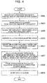
- Fig. 4 is a flowchart depicting the operation of the analysis device in Example 1.
- the vibration sensor 502, the rainfall sensor 503, and the temperature sensor 504 acquire time-series data (step S602).
- the fast Fourier transform module 505 transforms, from among the time-series data, the waveform data of the vibration acquired from the vibration sensor 502 into frequency (step S603).
- the classifying module 506 classifies the frequency-transformed data by the predetermined frequency width (step S604).
- the averaging module 507 calculates the average value for each classifying range (step S605).
- the time-series data output module 508 assigns the time before the frequency transform to the average value, to transform it back into time-series data (step S606).
- the ARX relational expression calculation module 509 calculates an ARX relational expression between the vibration data arranged in time series from frequency and the time-series data acquired from the rainfall sensor 503 and the temperature sensor 504 (step S607).
- the ARX relational expression calculation module 509 stores the coefficients of the relational expression in the relational expression storage memory 510 as the correlation (step S608).
- the notification module 511 notifies the waveform data acquired by the vibration sensor 502, the time-series data acquired by any of the rainfall sensor 503 and the temperature sensor 504, the frequency data, the feature value, or the correlation (ARX relational expression or its coefficients) between the feature value and the time-series data, to another information terminal or the like via the network 512 (step S609).
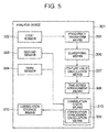
- FIG. 5 is a block diagram depicting the structure of the analysis device in the second exemplary embodiment.
- An analysis device 301 in this exemplary embodiment is an analysis device in an observation stage.
- the analysis device 301 includes a first sensor 302, a second sensor 303, and a third sensor 304.
- the analysis device 301 also includes frequency transform means 305, classifying means 306, feature value calculation means 307, time-series arrangement means 308, correlation check means 313, and correlation storage means 310.
- the correlation check means 313 includes correlation coincidence calculation means 309.
- the analysis device 301 in this exemplary embodiment has the structure in which the correlation coincidence calculation means 309 is included instead of the correlation calculation means 109 in the analysis device 101 in the first exemplary embodiment.
- the frequency transform means 305, the classifying means 306, the feature value calculation means 307, the time-series arrangement means 308, and the correlation check means 313 are realized, for example, by an information processing device such as a central processing unit (CPU) operating according to a program or hardware designed to perform specific computation and the like.
- the program is computer-readable, and is stored in a non-transitory information storage medium.
- the first sensor 302 is connected to the frequency transform means 305.
- the first sensor 302 acquires waveform data of light, sound, vibration, or the like generated from an object.
- the second sensor 303 and the third sensor 304 are connected to the correlation check means 313.
- the second sensor 303 and the third sensor 304 each acquire time-series data of an element that affects a change in the state of the object.
- the second sensor 303 and the third sensor 304 acquire time-series data of rainfall, temperature, humidity, sunlight intensity, object inclination, soil moisture content, etc.
- the frequency transform means 305 transforms, from among the time-series data, the waveform data acquired from the first sensor 302 into frequency.
- the classifying means 306 classifies the frequency-transformed data by a predetermined frequency width, and outputs the data to the feature value calculation means 307.
- the frequency width may be any frequency width.
- the analysis device 301 does not necessarily need to include the classifying means 306.
- the feature value calculation means 307 calculates a natural frequency as a feature value
- the analysis device 301 does not need to perform classifying.
- the classifying means 306 may exclude unnecessary frequency bands from the classifying process. In this case, subsequent processes such as feature value calculation may be omitted.
- the feature value calculation means 307 calculates, for each classifying range, a feature value based on the classified frequency, and outputs the calculated feature value to the time-series arrangement means 308.
- the feature value calculation means 307 calculates the feature value of each set of data, by calculating the average value, maximum value, dispersion, deviation, root mean square (RMS), etc. of each classifying range.
- the feature value calculation means 307 may determine a natural frequency (also referred to as a dominant frequency) in the frequency data, and set the frequency value of the natural frequency as the frequency feature value.
- the time-series arrangement means 308 assigns the time before the frequency transform to the calculated feature value to arrange it in time series.
- the time-series arrangement means 308 assigns, to the feature value, the time corresponding to the time-series data acquired by the second sensor 303 and the third sensor 304 to arrange the feature value in time-series.
- the time-series arrangement means 308 outputs the time-series data to the correlation coincidence calculation means 309.
- the correlation coincidence calculation means 309 calculates the correlation coincidence indicating the degree of coincidence between the correlation between the pre-stored feature value and the time-series data and the correlation between the newly calculated feature value and the time-series data. In detail, based on the waveform data-based feature value and the correlation stored in the correlation storage means 310 beforehand, the correlation coincidence calculation means 309 calculates the predicted value of the time-series data acquired by the second sensor 303 and the third sensor 304, and calculates the degree of coincidence with the measured value.
- the correlation coincidence calculation means 309 calculates the predicted value of the waveform data-based feature value, and calculates the degree of coincidence with the measured value.
- the correlation coincidence calculation means 309 may perform, other than the correlation calculation, calculation of an invariant expression between a plurality of sets of time-series data according to ARX.
- the correlation coincidence calculation means 309 may perform preprocessing. For example, the correlation coincidence calculation means 309 may perform simple averaging, moving averaging, integration, differentiation, etc., as preprocessing. After calculating the correlation coincidence, the correlation coincidence calculation means 309 may perform a process of notifying the correlation coincidence. In the case where the coincidence exceeds or is less than a predetermined threshold, the correlation coincidence calculation means 309 may notify it to the outside. Such preprocessing and notification process may be carried out by the correlation coincidence calculation means 309 or by other means.
- the analysis device 301 may have a structure in which the correlation coincidence calculation means 309 is added to the correlation check means 113 in the first exemplary embodiment.
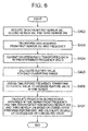
- Fig. 6 is a flowchart depicting the operation of the analysis device in the second exemplary embodiment.
- step S402 When the operation of the analysis device 301 starts, first the first sensor 302, the second sensor 303, and the third sensor 304 acquire time-series data (step S402).
- the frequency transform means 305 transforms, from among the time-series data, the waveform data acquired from the first sensor 302 into frequency (step S403).
- the classifying means 306 classifies the frequency-transformed data by the predetermined frequency width (step S404).
- the feature value calculation means 307 calculates the feature value for each classifying range (step S405).
- the time-series arrangement means 308 assigns the time before the frequency transform to the feature value, to arrange it in time series (step S406).
- the correlation coincidence calculation means 309 calculates, for the data arranged in time series from frequency and the time-series data from the second sensor 303 and the third sensor 304, the predicted value based on the correlation prepared in the correlation storage means 310 beforehand, and calculates the degree of coincidence with the measured value (step S407).
- the analysis device 301 in this exemplary embodiment can determine whether or not the correlation between the feature value based on the waveform data acquired from the first sensor 302 and the time-series data acquired from the second sensor 303 and the third sensor 304 coincides with the correlation stored previously.
- the correlation is disrupted if the object changes from an elastic body to a plastic body.
- the analysis device 301 can detect a change in the state of soil, and so is capable of prediction or early detection of sediment disasters.
- the analysis device 301 is equally capable of prediction or early detection of bridge breakages or tunnel collapses, by detecting concrete or metal degradation.
- Fig. 7 is a block diagram depicting the structure of an analysis device 701 in Example 2.
- the analysis device 701 includes three sensors, i.e. a vibration sensor 702, a rainfall sensor 703, and a temperature sensor 704.
- the analysis device 701 also includes a fast Fourier transform module 705, a classifying module 706, an averaging module 707, a time-series data output module 708, a predicted value error amount calculation module 709, a relational expression storage memory 710, and a prediction value error amount notification module 711.
- the prediction value error amount notification module 711 is connected to a network 712.
- the vibration sensor 702 is connected to the fast Fourier transform module 705.
- the vibration sensor 702 acquires waveform data of vibration of an object.
- the waveform data is time-series data.
- the rainfall sensor 703 and the temperature sensor 704 are connected to the predicted value error amount calculation module 709.
- the rainfall sensor 703 acquires time-series data of rainfall.
- the temperature sensor 704 acquires time-series data of temperature.
- the fast Fourier transform module 705 transforms the data acquired from the vibration sensor 702 into frequency, and outputs the transformed frequency to the classifying module 706.
- the classifying module 706 classifies the frequency-transformed data by a predetermined frequency width, and outputs the data to the averaging module 707.
- the averaging module 707 calculates the average value for each classifying range, and outputs the average value to the time-series data output module 708.
- the time-series data output module 708 assigns the time before the frequency transform to the average value to arrange it in time series, and outputs the data to the predicted value error amount calculation module 709.
- the predicted value error amount calculation module 709 calculates an ARX relational expression between the vibration data arranged in time series from frequency and the time-series data acquired from the rainfall sensor 703 and the temperature sensor 704, based on the coefficients of the ARX relational expression stored in the relational expression storage memory 710. The predicted value error amount calculation module 709 thus calculates the error amount between the predicted value and the measured value. The predicted value error amount calculation module 709 outputs the calculation result to the predicted value error amount notification module 711.
- the predicted value error amount notification module 711 notifies the acquired error amount to an external information processing terminal or the like (not depicted) via the network 712.
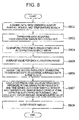
- Fig. 8 is a flowchart depicting the operation of the analysis device in Example 2.
- step S802 When the operation starts, first the vibration sensor 702, the rainfall sensor 703, and the temperature sensor 704 acquire data as time-series data (step S802).
- the fast Fourier transform module 705 transforms, from among the time-series data, the waveform data of the vibration acquired from the vibration sensor 702 into frequency (step S803).
- the classifying module 706 classifies the frequency-transformed data by the predetermined frequency width (step S804).
- the averaging module 707 calculates the average value for each classifying range (step S805).
- the time-series data output module 708 assigns the time before the frequency transform to the average value, to arrange it in time series (step S806).
- the predicted value error amount calculation module 709 calculates an ARX relational expression between the vibration data arranged in time series from frequency and the time-series data acquired by the rainfall sensor 703 and the temperature sensor 704, based on the coefficients stored in the relational expression storage memory 710. The predicted value error amount calculation module 709 thus calculates the error amount between the predicted value and the measured value (step S807).
- the predicted value error amount notification module 711 notifies the error amount to an external information processing terminal or the like (not depicted) via the network 712 (step S808).
- FIG. 9 is a block diagram depicting the structure of main parts of the analysis device according to the present invention.
- An analysis device 101 includes, as main components: a first sensor 102 for acquiring waveform data generated from an object; a second sensor 103 for acquiring time-series data of an element that affects a change in state of the object; frequency transform means 105 for acquiring a frequency of the waveform data; feature value calculation means 107 for calculating a feature value based on the frequency; time-series arrangement means 108 for assigning a time corresponding to the time-series data, to the feature value; and correlation check means 113 for checking a correlation between the feature value and the time-series data.
- the present invention is applicable to detection of signs of disasters such as sediment disasters, bridge breakages, and tunnel collapses.
Landscapes
- Physics & Mathematics (AREA)
- General Physics & Mathematics (AREA)
- Life Sciences & Earth Sciences (AREA)
- Engineering & Computer Science (AREA)
- Chemical & Material Sciences (AREA)
- Health & Medical Sciences (AREA)
- Biochemistry (AREA)
- Analytical Chemistry (AREA)
- Pathology (AREA)
- General Health & Medical Sciences (AREA)
- Immunology (AREA)
- Environmental & Geological Engineering (AREA)
- Signal Processing (AREA)
- General Life Sciences & Earth Sciences (AREA)
- Mathematical Physics (AREA)
- Spectroscopy & Molecular Physics (AREA)
- Medicinal Chemistry (AREA)
- Food Science & Technology (AREA)
- Remote Sensing (AREA)
- Geology (AREA)
- Acoustics & Sound (AREA)
- Ecology (AREA)
- Environmental Sciences (AREA)
- Hydrology & Water Resources (AREA)
- Biodiversity & Conservation Biology (AREA)
- Atmospheric Sciences (AREA)
- Testing Or Calibration Of Command Recording Devices (AREA)
- Investigating Or Analyzing Materials By The Use Of Ultrasonic Waves (AREA)
- Pit Excavations, Shoring, Fill Or Stabilisation Of Slopes (AREA)
- Testing Of Devices, Machine Parts, Or Other Structures Thereof (AREA)
Applications Claiming Priority (1)
| Application Number | Priority Date | Filing Date | Title |
|---|---|---|---|
| PCT/JP2013/006639 WO2015071925A1 (ja) | 2013-11-12 | 2013-11-12 | 分析装置、分析方法および分析プログラム |
Publications (2)
| Publication Number | Publication Date |
|---|---|
| EP3076169A1 true EP3076169A1 (de) | 2016-10-05 |
| EP3076169A4 EP3076169A4 (de) | 2017-06-21 |
Family
ID=53056897
Family Applications (1)
| Application Number | Title | Priority Date | Filing Date |
|---|---|---|---|
| EP13897388.8A Withdrawn EP3076169A4 (de) | 2013-11-12 | 2013-11-12 | Analysevorrichtung, analyseverfahren sowie analyseprogramm |
Country Status (4)
| Country | Link |
|---|---|
| US (1) | US20160266072A1 (de) |
| EP (1) | EP3076169A4 (de) |
| JP (1) | JP6107967B2 (de) |
| WO (1) | WO2015071925A1 (de) |
Families Citing this family (8)
| Publication number | Priority date | Publication date | Assignee | Title |
|---|---|---|---|---|
| US10509378B2 (en) * | 2016-11-07 | 2019-12-17 | FarmX Inc. | Systems and methods for soil modeling and automatic irrigation control |
| USRE50733E1 (en) | 2016-11-07 | 2026-01-06 | FarmX Inc. | Systems and methods for harmonic analysis of soil |
| KR101875018B1 (ko) * | 2016-11-15 | 2018-07-09 | 연세대학교 산학협력단 | 실시간 구조물 모니터링을 위한 구조물 동특성 추정 시스템 및 방법 |
| WO2021033547A1 (ja) * | 2019-08-20 | 2021-02-25 | 日本電気株式会社 | 地震観測装置、地震観測方法、及び、記録媒体 |
| JP7592487B2 (ja) | 2020-12-25 | 2024-12-02 | 能美防災株式会社 | 構造物劣化診断システム |
| JP7486672B2 (ja) * | 2021-07-15 | 2024-05-17 | 三菱電機株式会社 | 検査装置、検査システム、検査方法、及び検査プログラム |
| CN114036974B (zh) * | 2021-10-15 | 2024-11-26 | 东南大学 | 一种基于健康监测数据的桥梁冲刷动力识别方法 |
| JP7511539B2 (ja) | 2021-11-04 | 2024-07-05 | 公益財団法人鉄道総合技術研究所 | トンネル内の温度推定方法 |
Family Cites Families (10)
| Publication number | Priority date | Publication date | Assignee | Title |
|---|---|---|---|---|
| JP3925910B2 (ja) * | 2002-04-26 | 2007-06-06 | 財団法人電力中央研究所 | 常時微動計測に基づく建物の健全性診断法 |
| JP3894494B2 (ja) | 2003-07-10 | 2007-03-22 | 株式会社日立製作所 | 土砂災害予知システム、地域情報提供システム及び土砂災害予知方法 |
| JP3944744B2 (ja) * | 2003-07-29 | 2007-07-18 | 日本精工株式会社 | 異常診断装置及びこれを有する転がり軸受装置 |
| US8007839B2 (en) * | 2003-10-03 | 2011-08-30 | International Flavors & Fragrances | Conjugated dienamides, methods of production thereof, compositions containing same and uses thereof |
| JP2007271338A (ja) * | 2006-03-30 | 2007-10-18 | Toyota Motor Corp | 探傷方法および探傷装置 |
| JP4698466B2 (ja) * | 2006-03-31 | 2011-06-08 | 財団法人鉄道総合技術研究所 | 橋脚の健全性評価システムとその健全性評価プログラム |
| JP4859550B2 (ja) * | 2006-06-13 | 2012-01-25 | 財団法人電力中央研究所 | コンクリート構造部材の健全性判定方法 |
| JP4859557B2 (ja) * | 2006-06-30 | 2012-01-25 | 財団法人電力中央研究所 | コンクリート建物の健全性判定方法 |
| JP5280407B2 (ja) * | 2010-06-09 | 2013-09-04 | 日本電信電話株式会社 | 柱状構造物の損傷検知方法、損傷検知装置およびプログラム |
| JP5809174B2 (ja) * | 2013-01-09 | 2015-11-10 | 株式会社Nttファシリティーズ | 建物安全性検証システム、建物安全性検証方法及びプログラム |
-
2013
- 2013-11-12 WO PCT/JP2013/006639 patent/WO2015071925A1/ja not_active Ceased
- 2013-11-12 EP EP13897388.8A patent/EP3076169A4/de not_active Withdrawn
- 2013-11-12 US US15/030,960 patent/US20160266072A1/en not_active Abandoned
- 2013-11-12 JP JP2015547279A patent/JP6107967B2/ja active Active
Also Published As
| Publication number | Publication date |
|---|---|
| US20160266072A1 (en) | 2016-09-15 |
| JPWO2015071925A1 (ja) | 2017-03-09 |
| EP3076169A4 (de) | 2017-06-21 |
| WO2015071925A1 (ja) | 2015-05-21 |
| JP6107967B2 (ja) | 2017-04-05 |
Similar Documents
| Publication | Publication Date | Title |
|---|---|---|
| EP3076169A1 (de) | Analysevorrichtung, analyseverfahren sowie analyseprogramm | |
| Perez-Ramirez et al. | New methodology for modal parameters identification of smart civil structures using ambient vibrations and synchrosqueezed wavelet transform | |
| CN114036974A (zh) | 一种基于健康监测数据的桥梁冲刷动力识别方法 | |
| JP2020052740A (ja) | 異常検知装置、異常検知方法及びプログラム | |
| EP2937689A1 (de) | Adaptives grundlinienschadenerkennungssystem und verfahren | |
| CA2960792A1 (en) | Apparatus and method for ensembles of kernel regression models | |
| CN113343541A (zh) | 长大跨桥梁的涡激振动预警方法、装置及终端 | |
| KR101271694B1 (ko) | 시계열데이터의 연속적 결측값 대체 시스템 및 그 방법 | |
| US20180188104A1 (en) | Signal detection device, signal detection method, and recording medium | |
| CN112380073A (zh) | 一种故障位置的检测方法、装置及可读存储介质 | |
| JPWO2015174067A1 (ja) | 情報処理装置、異常検出方法、及び、記録媒体 | |
| US9857460B2 (en) | Waveform estimation device and waveform estimation method | |
| US20200278241A1 (en) | Vibration determination device, vibration determination method, and program | |
| Rokhsati et al. | Two-stage structural damage detection using modal strain energy and natural frequencies: Numerical and experimental study | |
| CN105698915B (zh) | 一种光纤振源识别方法及装置、系统 | |
| US12340284B2 (en) | Time-series data processing method | |
| Souza et al. | Impact of damping models in damage identification | |
| US9371116B2 (en) | Method for predicting at least one movement of a ship under the effect of the waves | |
| CN112611854B (zh) | 一种含水量在线分析系统及方法 | |
| EP3351959A1 (de) | Vorrichtung und verfahren zur durchführung einer konsistenzprüfung mit nichtlinearen filtern für prognostische wahrscheinlichkeitsdichtefunktionen | |
| EP3605051A1 (de) | Analysevorrichtung, diagnosevorrichtung, analyseverfahren und computerlesbares aufzeichnungsmedium | |
| CN114938339B (zh) | 一种数据处理方法和相关装置 | |
| CN107003413B (zh) | 用于确定原始测量值的统计特性的方法和设备 | |
| KR20230073210A (ko) | 진동 해석 시스템, 및 진동 해석 방법 | |
| JP7772106B2 (ja) | 監視システム、監視方法及びプログラム |
Legal Events
| Date | Code | Title | Description |
|---|---|---|---|
| PUAI | Public reference made under article 153(3) epc to a published international application that has entered the european phase |
Free format text: ORIGINAL CODE: 0009012 |
|
| 17P | Request for examination filed |
Effective date: 20160613 |
|
| AK | Designated contracting states |
Kind code of ref document: A1 Designated state(s): AL AT BE BG CH CY CZ DE DK EE ES FI FR GB GR HR HU IE IS IT LI LT LU LV MC MK MT NL NO PL PT RO RS SE SI SK SM TR |
|
| AX | Request for extension of the european patent |
Extension state: BA ME |
|
| DAX | Request for extension of the european patent (deleted) | ||
| A4 | Supplementary search report drawn up and despatched |
Effective date: 20170522 |
|
| RIC1 | Information provided on ipc code assigned before grant |
Ipc: G01H 1/00 20060101ALI20170516BHEP Ipc: G01M 99/00 20110101ALI20170516BHEP Ipc: G01V 1/00 20060101ALI20170516BHEP Ipc: G01H 3/00 20060101ALI20170516BHEP Ipc: G01W 1/14 20060101ALI20170516BHEP Ipc: G01N 29/44 20060101AFI20170516BHEP Ipc: G01N 29/14 20060101ALI20170516BHEP Ipc: G01N 33/24 20060101ALI20170516BHEP Ipc: G01H 3/04 20060101ALI20170516BHEP Ipc: G01M 7/00 20060101ALI20170516BHEP Ipc: G01W 1/02 20060101ALI20170516BHEP Ipc: G01N 29/46 20060101ALI20170516BHEP Ipc: G01H 13/00 20060101ALI20170516BHEP |
|
| STAA | Information on the status of an ep patent application or granted ep patent |
Free format text: STATUS: THE APPLICATION IS DEEMED TO BE WITHDRAWN |
|
| 18D | Application deemed to be withdrawn |
Effective date: 20171220 |