EP3076218A1 - Appareil à platine et microscope - Google Patents
Appareil à platine et microscope Download PDFInfo
- Publication number
- EP3076218A1 EP3076218A1 EP16000723.3A EP16000723A EP3076218A1 EP 3076218 A1 EP3076218 A1 EP 3076218A1 EP 16000723 A EP16000723 A EP 16000723A EP 3076218 A1 EP3076218 A1 EP 3076218A1
- Authority
- EP
- European Patent Office
- Prior art keywords
- plate
- stage
- holding
- holding means
- plate member
- Prior art date
- Legal status (The legal status is an assumption and is not a legal conclusion. Google has not performed a legal analysis and makes no representation as to the accuracy of the status listed.)
- Withdrawn
Links
- 238000003825 pressing Methods 0.000 claims description 75
- 230000006835 compression Effects 0.000 claims description 12
- 238000007906 compression Methods 0.000 claims description 12
- 230000005489 elastic deformation Effects 0.000 claims description 11
- 239000011521 glass Substances 0.000 description 64
- 238000013519 translation Methods 0.000 description 54
- 230000002093 peripheral effect Effects 0.000 description 52
- 230000006870 function Effects 0.000 description 33
- 230000008859 change Effects 0.000 description 30
- 230000007423 decrease Effects 0.000 description 22
- 230000008602 contraction Effects 0.000 description 11
- 230000007246 mechanism Effects 0.000 description 11
- 230000003287 optical effect Effects 0.000 description 11
- 238000005259 measurement Methods 0.000 description 9
- 229910000838 Al alloy Inorganic materials 0.000 description 6
- VYPSYNLAJGMNEJ-UHFFFAOYSA-N Silicium dioxide Chemical compound O=[Si]=O VYPSYNLAJGMNEJ-UHFFFAOYSA-N 0.000 description 6
- 238000003860 storage Methods 0.000 description 6
- 229910045601 alloy Inorganic materials 0.000 description 4
- 239000000956 alloy Substances 0.000 description 4
- 238000003745 diagnosis Methods 0.000 description 4
- 239000000463 material Substances 0.000 description 4
- 230000015572 biosynthetic process Effects 0.000 description 3
- 238000000034 method Methods 0.000 description 3
- 238000010827 pathological analysis Methods 0.000 description 3
- 230000009467 reduction Effects 0.000 description 3
- 230000009471 action Effects 0.000 description 2
- 230000036760 body temperature Effects 0.000 description 2
- 238000001514 detection method Methods 0.000 description 2
- 230000020169 heat generation Effects 0.000 description 2
- 238000003780 insertion Methods 0.000 description 2
- 230000037431 insertion Effects 0.000 description 2
- 238000004519 manufacturing process Methods 0.000 description 2
- 230000000877 morphologic effect Effects 0.000 description 2
- 238000012545 processing Methods 0.000 description 2
- 238000005096 rolling process Methods 0.000 description 2
- 239000004065 semiconductor Substances 0.000 description 2
- 239000000758 substrate Substances 0.000 description 2
- 238000005452 bending Methods 0.000 description 1
- 230000005540 biological transmission Effects 0.000 description 1
- 239000000470 constituent Substances 0.000 description 1
- 230000000694 effects Effects 0.000 description 1
- 229910052736 halogen Inorganic materials 0.000 description 1
- 150000002367 halogens Chemical class 0.000 description 1
- 238000003384 imaging method Methods 0.000 description 1
- 230000003902 lesion Effects 0.000 description 1
- 238000012986 modification Methods 0.000 description 1
- 230000004048 modification Effects 0.000 description 1
- 230000004044 response Effects 0.000 description 1
- 230000000007 visual effect Effects 0.000 description 1
Images








Classifications
-
- G—PHYSICS
- G02—OPTICS
- G02B—OPTICAL ELEMENTS, SYSTEMS OR APPARATUS
- G02B21/00—Microscopes
- G02B21/24—Base structure
- G02B21/26—Stages; Adjusting means therefor
-
- G—PHYSICS
- G02—OPTICS
- G02B—OPTICAL ELEMENTS, SYSTEMS OR APPARATUS
- G02B21/00—Microscopes
- G02B21/36—Microscopes arranged for photographic purposes or projection purposes or digital imaging or video purposes including associated control and data processing arrangements
- G02B21/362—Mechanical details, e.g. mountings for the camera or image sensor, housings
Definitions
- the present invention relates to a stage apparatus which moves while a slide is placed thereon and a microscope equipped with the stage apparatus.
- an optical microscope has been used by pathologists for pathological diagnosis as a means for implementing fine observation of a tissue segment of a lesion.
- a slide glass on which an observation target is placed is placed on a stage for a microscope, and the stage is moved to locate the observation region immediately below an objective lens (observation visual field).
- observation visual field an objective lens
- a stage apparatus for a microscope is formed from an XY stage so as to be capable of arbitrarily moving in two-dimensional directions and is required to implement high-precision observation position management on the XY stage mounted on the microscope.
- Japanese Patent Laid-Open Nos. 2013-64731 and 2013-7718 disclose techniques associated with positioning element techniques for XY stages and designed to hold a scale used for a linear encoder or the like with high precision in one direction in which measurement is performed.
- thermal expansions cause fine expansion/contraction (thermal drift) between a plurality of members.
- the thermal expansion/contraction difference between the respective members causes stress in the fixed portion of each member. This can cause distortion in each member of the XY stage in the X and Y directions.
- the influence of distortion on a glass scale for observation position management of the XY stage can make it difficult to implement high-precision observation position management on the XY stage.
- Japanese Patent Laid-Open Nos. 2013-64731 and 2013-7718 each disclose an arrangement for holding a glass scale with high precision in one direction in which measurement is performed, but give no consideration to an arrangement for suppressing the influence of expansion/contraction (thermal drift) caused by thermal expansion. That is, Japanese Patent Laid-Open Nos. 2013-64731 and 2013-7718 each give no consideration to an arrangement for suppressing the occurrence of distortion caused by expansion/contraction caused in members by thermal expansion.
- the present invention has been made in consideration of the above problem, and provides a stage apparatus which can implement high-precision observation position management by suppressing the occurrence of distortion by the expansion/contraction of members caused by thermal expansion.
- Fig. 1 is a perspective view showing the basic arrangement of an observation position management microscope system (to be referred to as a microscope system 10 hereinafter) according to this embodiment.
- the microscope system 10 includes a microscope body 101, a stage apparatus 200, an adapter unit 300 for camera attachment, a digital camera 400, and a control unit 500.
- the control unit 500 includes a controller 501 and a display 502.
- a microscope base stand 121 as a component of the microscope body 101 is a robust body frame for the attachment of various types of structures of the microscope.
- An eyepiece microscope base stand 122 is fixed to the microscope base stand 121.
- An eyepiece lens barrel 123 (binoculars in this case) is connected to the eyepiece microscope base stand 122.
- a light source box 124 accommodates a light source for transmission observation (for example, a halogen lamp or LED) and is attached to the microscope base stand 121.
- a Z knob 125 is a knob for moving a base 130 in the Z-axis direction (up/down direction: vertical direction).
- the stage apparatus 200 which provides an observation position management function is mounted on the base 130.
- the base 130 is attached to the microscope base stand 121 with a base moving mechanism 131 which moves the base 130 in the Z direction in accordance with the rotation of the Z knob 125.
- a revolver 127 has a structure which allows the attachment of the plurality of types of objective lens units 126. Rotating the revolver 127 can select a desired objective lens unit for observation with the microscope.
- the stage apparatus 200 includes an XY stage on which a slide glass 20 is placed and which moves on an X-Y plane including the X direction and the Y direction.
- An XY scale plate 2 including a high-precision scale in the X and Y directions is held on the upper surface of a X stage plate 3 ( Fig. 2 ) as a component of the stage apparatus 200.
- the details of the X stage plate 3 as a component of the stage apparatus 200 will be described later.
- the stage apparatus 200 is connected to the controller 501 (control apparatus) via, for example, a USB interface cable 112. In accordance with a moving instruction from the controller 501, the stage apparatus 200 moves its stage position in the X and Y directions and notifies the controller 501 of the stage position.
- the adapter unit 300 is an adapter for camera attachment which functions as an attachment unit for attaching the digital camera 400 to the eyepiece microscope base stand 122 through a microscope base stand mount 128.
- the digital camera 400 is detachably attached to the microscope body 101 with the adapter unit 300 and the microscope base stand mount 128 so as to hold a predetermined positional relationship with the eyepiece microscope base stand 122.
- the digital camera 400 captures a microscopic image obtained by the microscope body 101.
- the digital camera 400 aims at recoding evidences.
- the digital camera 400 is connected to the controller 501 via, for example, a USB interface cable 111, and captures an observation image under the microscope in response to an instruction from the controller 501.
- the captured observation image is displayed on the display 502 (display unit) under the control of the controller 501.
- the imaging function of the digital camera 400 includes a live image capturing function for performing live viewing to display an output from an image sensor on a monitor in real time and a still image capturing function.
- the live image capturing function is lower in resolution than the still image capturing function.
- the live image capturing function and the still image capturing function can transmit captured images (moving and still images) to an external apparatus via a predetermined interface (a USB interface in this embodiment).
- the XY stage of the stage apparatus 200 is configured to be movable in the first direction (for example, the X direction) in a plane and the second direction (for example, the Y direction) intersecting with the first direction in an in-plane direction.
- the third direction (Z direction) intersecting with the first direction (X direction) and the second direction (Y direction) corresponds to the optical axis of the microscope.
- the stage apparatus 200 includes the plate-like X stage plate 3 (stage plate) having a spread in the first direction and the second direction intersecting with the first direction and the XY scale plate 2 (plate member) having a linear expansion coefficient different from that of the X stage plate 3 (stage plate).
- a moving mechanism in the first direction is called an X stage 210
- a moving mechanism in the second direction intersecting with the first direction in an in-plane direction is called a Y stage 220.
- the X stage 210 is arranged on the Y stage 220 and is configured to be movable in the arrow X direction with a sliding mechanism (not shown) including a linear guide formed on the Y stage 220.
- the Y stage 220 is arranged on a base 130 functioning as a base member of the stage apparatus 200.
- the Y stage 220 is configured to be movable in the arrow Y direction with a sliding mechanism (not shown) including a linear guide formed on the base 130.
- the XY stage of the stage apparatus 200 functions as a two-dimensional moving mechanism constituted by the X stage 210 and the Y stage 220.
- this embodiment has exemplified the arrangement having the X stage 210 arranged on the Y stage 220, the scope of the present invention is not limited to this example, and the XY stage may be formed by arranging the stages in the reverse order.
- the X stage 210 includes the X stage plate 3 as the main body of the X stage 210.
- the XY scale plate 2 integrally formed with an XY glass scale 2s is placed on the X stage plate 3.
- the XY glass scale 2s is integrally formed with the XY scale plate 2 by, for example, being bonded to its upper surface.
- Arranging the XY scale plate 2 on the X stage plate 3 of the X stage 210 will arrange the XY glass scale 2s on the X stage plate 3 of the X stage 210 through the XY scale plate 2.
- the slide glass 20 is placed on the XY scale plate 2 and held at a predetermined position.
- An X-direction scale 8 (scale marks) and a Y-direction scale 7 (scale marks) are accurately formed on the XY glass scale 2s.
- the X-direction scale 8 is used to measure X-direction position information used for observation position management at the time of movement in the X direction.
- the Y-direction scale 7 is used to measure Y-direction position information used for observation position management at the time of movement in the Y direction.
- an XY crosshatch 6 is accurately formed on the XY glass scale 2s such that an X-direction scale for the measurement of X-direction position information intersects with a Y-direction scale for the measurement of Y-direction position information.
- the XY crosshatch 6 is used as a reference for alignment in the X direction and the Y direction.
- the XY crosshatch 6 has a reference position S 0 .
- the microscope base stand 121 as a component of the microscope body 101 has an X-direction sensor for reading the X-direction scale 8 and a Y-direction sensor for reading the Y-direction scale 7, which are arranged above the XY glass scale 2s. Detection results obtained by the X-direction sensor and the Y-direction sensor are transmitted to the controller 501 (control apparatus), and the position of the stage apparatus 200 is controlled under the position control of the controller 501 (control apparatus).
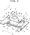
- Fig. 3 exemplarily shows an arrangement in which the XY glass scale 2s is supported on the upper surface side of the X stage plate 3.
- the arrangement of this embodiment is not limited to this example.
- the stage apparatus 200 can be configured such that the XY glass scale 2s is supported on the lower surface side of the X stage plate 3 through the XY scale plate 2.
- the X-direction sensor and the Y-direction sensor are arranged on the microscope base stand 121 at, for example, positions below the XY glass scale 2s.
- the controller 501 can perform position control to position the stage apparatus 200 with respect to an observation target 21 in the slide glass 20 based on the information of the reference position S 0 and the obtained information of the relative position. Position control by the stage apparatus 200 makes it possible to easily reproduce an observation position (the position of the observation target 21 in the slide glass 20) when performing morphological diagnosis, functional diagnosis, and capturing an evidence image with a digital camera in pathological diagnosis.
- Patterns are produced on the XY crosshatch 6, the X-direction scale 8, and the Y-direction scale 7 on the XY glass scale 2s by using a nanotechnology using a semiconductor exposure apparatus.
- the X-direction scale 8 formed from a set of lines in the Y-axis direction and the Y-direction scale 7 formed from a set of lines in the X-axis direction are integrally produced on a silica glass substrate with, for example, an accuracy of 5 nm to 10 nm by a nanotechnology.
- the XY crosshatch 6, the X-direction scale 8, and the Y-direction scale 7 can also be produced by drawing with an exposure apparatus. However, in order to implement low cost production, nano-imprinting can also be used.
- the ratio of a change in length to an increase in temperature is a linear expansion rate (linear expansion coefficient).
- a linear expansion coefficient ⁇ is defined as the rate of change in length with respect to temperature per unit length.
- the linear expansion coefficient ⁇ is defined by equation (1) given below.
- Letting L 0 be the original length of the object before a change in temperature and L be the length of the object when the temperature has changed by t
- the length L can be expressed by equation (2) given below.
- ⁇ 1 / L ⁇ dL / dt
- the length L of the object is proportional to the length L 0 of the object before the change in temperature and the linear expansion coefficient ⁇ .
- it is effective to decrease, for example, the linear expansion coefficient ( ⁇ ) or the length of the object.
- the X stage plate 3 is formed from, for example, an aluminum alloy to decrease the weight of the moving unit and ensure the rigidity of the stage apparatus.
- a linear expansion coefficient ⁇ 1 of the aluminum alloy is 24 x 10 -6 /°C.
- a translation constraining member 16, a translation constraining member 17, and a pressing force reception member 18 are formed from, for example, an aluminum alloy. Forming these members by using members having the same linear expansion coefficient as that of the X stage plate 3 can inhibit stress caused by relative deformation differences (length increase/decrease differences) caused by a change in temperature from acting on the XY scale plate 2, thereby suppressing distortion caused in the XY scale plate 2.
- the XY glass scale 2s is formed from glass, for example, silica glass, which is a material having a very small linear expansion coefficient, so as to be used as a reference for the implementation of high-precision observation position management.
- the XY scale plate 2 is formed from a low-expansion alloy, which is a material having a very small linear expansion coefficient, so as to be used as a reference for the implementation of high-precision observation position management.
- Both silica glass and a low-expansion alloy have an equal linear expansion coefficient ⁇ 2, which is about 0.5 x 10 -6 /°C.
- the slide glass 20 fixed on the XY scale plate 2 is made of glass, which has almost the same linear expansion coefficient as that of the XY glass scale 2s and the XY scale plate 2.
- the XY glass scale 2s, the XY scale plate 2, and the slide glass 20 have similar linear expansion coefficients, which are smaller than the linear expansion coefficient of the X stage plate 3. For this reason, relative deformation differences (length increase/decrease differences) caused by a temperature change have only small influences on the XY glass scale 2s, the XY scale plate 2, and the slide glass 20.
- the following arrangement for holding the XY scale plate 2 on the X stage plate 3 reduces the influence of a relative deformation difference (length increase/decrease difference) caused by a temperature change in accordance with the difference between the two linear expansion coefficients.
- a stepped portion 25 having a concave shape for the arrangement of the XY scale plate 2 is formed on the upper surface of the X stage plate 3, as shown in Fig. 3 .
- the depth of the concave portion is almost the same as the height (thickness) of the XY scale plate 2. While the XY scale plate 2 is arranged on the stepped portion 25 of the X stage plate 3, the upper surface of the XY scale plate 2 is almost flush with the upper surface of the X stage plate 3.
- a plurality of holding units for holding the XY scale plate 2 are formed on the stepped surface of the stepped portion 25.
- the reference surface of the first holding unit 3a1 and the holding surfaces of the second holding unit 3a2 to the fourth holding unit 3a4 have, for example, circular cross-sectional shapes.
- the height of the first holding unit 3a1 to the fourth holding unit 3a4 is higher than that of the stepped surface of the stepped portion 25.
- Holding the XY scale plate 2 by using the first holding unit 3a1 to the fourth holding unit 3a4 can shorten the length of a portion where the XY scale plate 2 is in contact with the X stage plate 3 as compared with a case in which the XY scale plate 2 is directly mounted on the stepped surface of the stepped portion 25.
- This arrangement can reduce a change in the length of the object caused by a change in temperature.
- reducing a change in the length of the object caused by a change in temperature can hold (fix) the XY scale plate 2 on the X stage plate 3 with high precision without causing stress originating from a thermal expansion/contraction difference in the XY scale plate 2.
- Using such holding structures for the XY scale plate 2 can hold a focus position in the optical axis direction (Z direction) relative to the XY glass scale 2s with high precision.
- a female threaded portion which can be connected to a connecting member 4 (male threaded portion) is formed on the holding surface (reference surface) of the first holding unit 3a1. Fastening the connecting member 4 (male threaded portion) with the female portion of the first holding unit 3a1 will integrally hold (fix) the XY scale plate 2 on the X stage plate 3 without any backlash.
- An end portion 32 of the XY scale plate 2 arranged on the second holding unit 3a2 is provided with a pressing member 5 (biasing portion) and an opening portion 2c.
- An end portion 33 of the XY scale plate 2 arranged on the third holding unit 3a3 is provided with a pressing member 5 (biasing portion) and an opening portion 2d.
- an end portion 34 of the XY scale plate 2 arranged on the fourth holding unit 3a4 is provided with a pressing member 5 (biasing portion).
- Opening portions 13 for holding the pressing members 5 provided on the end portions of the XY scale plate 2 are respectively formed on the holding surfaces of the second holding unit 3a2 to the fourth holding unit 3a4.
- the translation constraining member 16 is arranged on the end portion 32 of the XY scale plate 2 so as to cover the pressing member 5.
- the translation constraining member 16 is fixed on the X stage plate 3 with a connecting member 9 (male threaded portion).
- the translation constraining member 16 fixed on the X stage plate 3 constrains the translational movement (deformation in the translation direction) of the XY scale plate 2 in the -Y direction, and also constrains the movement (lift) of the XY scale plate 2 in the Z direction (vertical direction).
- the translation constraining member 17 is arranged on the end portion 33 of the XY scale plate 2 so as to cover the pressing member 5.
- the translation constraining member 17 is fixed on the X stage plate 3 with a connecting member 9 (male threaded portion).
- the translation constraining member 17 fixed on the X stage plate 3 constrains the translational movement (deformation in the translation direction) of the XY scale plate 2 in the -X direction, and also constrains the movement (lift) of the XY scale plate 2 in the Z direction (vertical direction).
- the pressing force reception member 18 is arranged on the end portion 34 of the XY scale plate 2 so as to cover the pressing member 5.
- the pressing force reception member 18 is fixed on the X stage plate 3 with a connecting member 9 (male threaded portion).
- the pressing force reception member 18 constrains the movement (lift) of the XY scale plate 2 in the Z direction (vertical direction) while allowing the XY scale plate 2 to move in the X and Y directions.
- Fig. 5 is a view showing the arrangement of the XY scale plate 2 seen from the reverse surface side of the XY scale plate 2 relative to the display in Fig. 3 .
- the arrangement of the pressing members 5 (biasing portions), the opening portion 2c, and the opening portion 2d will be described with reference to Fig. 5 .
- the XY scale plate 2 (plate member) includes the pressing members 5 (biasing portions), on the end portions held by the second holding unit 3a2 and the third holding unit 3a3, which generate biasing forces in the third direction intersecting with the first and second directions. Also, the XY scale plate 2 (plate member) includes opening portions, in the end portions held by the second holding unit 3a2 and the third holding unit 3a3, each of which has an opening shape with a longer opening width in a direction to allow deformation than in a direction to constrain deformation.
- the XY scale plate 2 is fixed on the X stage plate 3 with the connecting member 4.
- the end portion 32 of the XY scale plate 2 is provided with the pressing member 5 (biasing portion) and the opening portion 2c.
- the opening portion 2c has a rectangular shape with one side being elongated along the X-axis.
- the translation constraining member 16 (constraining member) of the second holding unit 3a2 has a convex portion 16a (engaging portion) inserted into the opening portion 2c. While the convex portion 16a is in contact with the opening portion 2c, the translation constraining member 16 constrains deformation in the second direction in which the convex portion 16a is in contact with the opening portion 2c. While there is a gap between the convex portion 16a (engaging portion) and the opening portion 2c, the translation constraining member 16 allows deformation in the first direction.
- the convex portion 16a formed on the translation constraining member 16 engages with the opening portion 2c. While the convex portion 16a of the translation constraining member 16 engages with the opening portion 2c, there is a gap between the convex portion 16a and the opening portion 2c in the X-axis direction (+X direction and -X direction), and hence the XY scale plate 2 can move in the X-axis direction.
- the translation constraining member 16 constrains the translational movement (deformation in the translation direction) of the XY scale plate 2 in the -Y direction, and also constrains the movement (lift) of the XY scale plate 2 in the Z direction (vertical direction). Note that it is possible to eliminate the gap between the convex portion 16a and the opening portion 2c in the +Y direction to constrain movement in the Y-axis direction (+Y direction and -Y direction).
- the end portion 33 of the XY scale plate 2 is provided with the pressing member 5 and the opening portion 2d.
- the opening portion 2d has a rectangular shape with one side being elongated along the Y-axis.
- the translation constraining member 17 (constraining member) of the third holding unit 3a3 has a convex portion 17a (engaging portion) inserted into the opening portion 2d. While the convex portion 17a is in contact with the opening portion 2d, the translation constraining member 17 constrains deformation in the first direction in which the convex portion 17a is in contact with the opening portion 2d. While there is a gap between the convex portion 17a (engaging portion) and the opening portion 2d, the translation constraining member 17 allows deformation in the second direction.
- the convex portion 17a formed on the translation constraining member 17 engages with the opening portion 2d. While the convex portion 17a of the translation constraining member 17 engages with the opening portion 2d, there is a gap between the convex portion 17a and the opening portion 2d in the Y-axis direction (+Y direction and -Y direction), and hence the XY scale plate 2 can move in the Y-axis direction.
- the translation constraining member 17 constrains the translational movement (deformation in the translation direction) of the XY scale plate 2 in the -X direction, and also constrains the movement (lift) of the XY scale plate 2 in the Z direction (vertical direction). Note that it is possible to eliminate the gap between the convex portion 17a and the opening portion 2d in the +X direction to constrain movement in the X-axis direction (+X direction and -X direction).
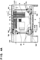
- Fig. 4A is a view showing the X stage 210 as a component of the stage apparatus 200 when seen from the upper surface side.
- the XY scale plate 2 is held (fixed) on the X stage plate 3 with the connecting member 4.
- the XY scale plate 2 is pressed against the X stage plate 3 with biasing forces from the translation constraining member 16, the translation constraining member 17, the pressing force reception member 18, and the respective pressing members 5, thereby constraining movement (lift) in the Z direction (vertical direction).
- the translation constraining member 16 constrains the movement (deformation in the translation direction) of the XY scale plate 2 in the - Y direction.
- the translation constraining member 17 constrains the movement (deformation in the translation direction) of the XY scale plate 2 in the -X direction.
- the XY scale plate 2 is held between the pressing force reception member 18 and the fourth holding unit 3a4 so as to be movable in the X-Y plane.
- the center of the holding surface (reference surface) of the first holding unit 3a1 of the four holding units (3a1 to 3a4), which is arranged nearest to the reference position S 0 is set as the origin (reference position) (G in Fig. 4A ) of X and Y axes on the XY scale plate 2.
- the origin G of the X and Y axes coincides with the center of the connecting member 4, and the connecting member 4 fixes the XY scale plate 2 on the X stage plate 3 at the origin G (reference position) of the X and Y axes.
- the central position of the holding surface of the first holding unit 3a1 is a reference position in the first and second directions.
- the second holding unit 3a2 is arranged on the first-direction axis passing through the reference position, and the center of the holding surface of the second holding unit 3a2 is arranged on the X-axis (first-direction axis) passing through the origin G (reference position).
- the third holding unit 3a3 is arranged on the second-direction axis passing through the reference position.
- the center of the holding surface of the third holding unit 3a3 is arranged on the Y-axis (second-direction axis) passing through the origin G and intersecting with the X-axis (first-direction axis).
- the center of the holding surface of the fourth holding unit 3a4 is arranged near a diagonal line with respect to the origin G (reference position).
- Fig. 4B is a view showing the cross-sectional structure of the first holding unit 3a1 along the b-b cross-section of Fig. 4A .
- the first holding unit 3a1 holds the XY scale plate 2 (plate member) on the stage plate.
- the XY scale plate 2 is held (fixed) on the X stage plate 3 with the connecting member 4.
- the XY glass scale 2s is arranged on the XY scale plate 2.
- a hole portion 2b for the insertion of the connecting member 4 is formed in the XY scale plate 2.
- An X stage plate spot facing hole 3b is formed in the holding surface of the first holding unit 3a1 which holds the XY scale plate 2.
- the connecting member 4 is configured to fit in the hole portion 2b and the X stage plate spot facing hole 3b without any backlash. This makes it possible to accurately position the connecting member 4 to the origin G (reference position).
- the connecting member 4 is fastened with the female threaded portion of the first holding unit 3a1 to integrally fix the XY scale plate 2 on the X stage plate 3 at the origin G (reference position).
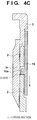
- Fig. 4C is a view showing the c-c cross-section of Fig. 4A .
- the second holding unit 3a2 holds the XY scale plate 2 (plate member) on the X stage plate.
- the second holding unit 3a2 allows relative deformation caused between the X stage plate 3 and the XY scale plate 2 (plate member) in the first direction based on a linear expansion coefficient difference and constrains the deformation in the second direction.
- the convex portion 16a is formed on the translation constraining member 16. While the translation constraining member 16 is fixed on the X stage plate 3, the convex portion 16a is fitted in the opening portion 2c formed in the XY scale plate 2. The convex portion 16a of the translation constraining member 16 is pressed against the side surface of the opening portion 2c located on the X-axis in the arrow direction in Fig. 4C without any backlash.
- the end portion 32 of the XY scale plate is provided with the pressing member 5.
- the biasing force of the pressing member 5 presses the lower surface of the translation constraining member 16 (a portion corresponding to a lower surface concave portion 18a in Fig. 4E ) while the translation constraining member 16 is fixed on the X stage plate 3.
- a reactive force received by the pressing member 5 is transmitted to the XY scale plate 2 to press the XY scale plate 2 against the holding surface of the second holding unit 3a2.
- the movement (lift) of the XY scale plate 2 in the +Z direction (vertical direction) is constrained by using the biasing force of the pressing member 5.
- the translation constraining member 16 of the second holding unit 3a2 functions as a constraining member which presses the XY scale plate 2 (plate member) downward in the -Z direction (third direction), based on the biasing force, to constrain the deformation of the XY scale plate 2 (plate member) in the third direction relative to the X stage plate.
- the XY scale plate 2 and the X stage plate 3 relatively freely move on the X-axis, thereby suppressing the occurrence of stress.
- Fig. 4D is a view showing the d-d cross-section of Fig. 4A .
- the third holding unit 3a3 holds the XY scale plate 2 (plate member) on the X stage plate.
- the third holding unit 3a3 holds the XY scale plate 2 (plate member) on the X stage plate.
- the third holding unit 3a3 constrains relative deformation caused between the X stage plate 3 and the XY scale plate 2 (plate member) in the first direction based on a linear expansion coefficient difference and allows the deformation in the second direction.
- the convex portion 17a is formed on the translation constraining member 17. While the translation constraining member 17 is fixed on the X stage plate 3, the convex portion 17a is fitted in the opening portion 2d formed in the XY scale plate 2. The convex portion 17a of the translation constraining member 17 is pressed against the side surface of the opening portion 2d located on the X-axis in the arrow direction in Fig. 4D without any backlash.
- the end portion 33 of the XY scale plate is provided with the pressing member 5.
- the biasing force of the pressing member 5 presses the lower surface of the translation constraining member 17 (a portion corresponding to a lower surface concave portion 18a in Fig. 4E ) while the translation constraining member 17 is fixed on the X stage plate 3.
- a reactive force received by the pressing member 5 is transmitted to the XY scale plate 2 to press the XY scale plate 2 against the holding surface of the third holding unit 3a3.
- the movement (lift) of the XY scale plate 2 in the +Z direction (vertical direction) is constrained by using the biasing force of the pressing member 5.
- the translation constraining member 17 of the third holding unit 3a3 functions as a constraining member which presses the XY scale plate 2 (plate member) downward in the -Z direction (third direction), based on the biasing force, to constrain the deformation of the XY scale plate 2 (plate member) in the third direction relative to the X stage plate.
- the XY scale plate 2 and the X stage plate 3 relatively freely move on the Y-axis, thereby suppressing the occurrence of stress.
- Fig. 4E is a view showing the e-e cross-section of Fig. 4A , which shows the cross-sectional structure of the fourth holding unit 3a4.
- the pressing member 5 can be formed as, for example, a ball plunger.
- the pressing member 5 includes an elastic member 5b (compression spring) which generates a biasing force against the upper surface of the X stage plate 3 in the vertical direction, a housing 5c which holds the elastic member 5b, and a spherical member 5a (ball member).
- One end (lower end) of the elastic member 5b (compression spring) is fixed to the housing 5c.
- the other end (upper end) of the elastic member 5b (compression spring) is connected to the spherical member 5a (ball member).
- a housing fixing portion 14 for fixing the housing 5c is formed on the XY scale plate 2.
- a female threaded portion is formed in the inner circumferential surface of the housing fixing portion 14, and for example, a male threaded portion is formed on the outer circumferential surface of the housing 5c.
- Engaging the male threaded portion with the female threaded portion can fix the pressing member 5 to the XY scale plate 2.
- the pressing force reception member 18 is fixed on the X stage plate 3
- a reactive force received by the pressing member 5 upon the pressing operation is transmitted to the XY scale plate 2 to press the XY scale plate 2 against the holding surface of the fourth holding unit 3a4.
- the movement (lift) of the XY scale plate 2 in the Z direction (vertical direction) is constrained by using the biasing force of the elastic member 5b.
- the XY scale plate 2 and the X stage plate 3 can relatively move in the X and Y directions.
- a gap is provided between the opening portion 13 formed in the holding surface of the fourth holding unit 3a4 and the housing fixing portion 14 to allow relative movement of the XY scale plate 2 and the X stage plate 3 in the X and Y directions.
- the movement of the XY scale plate 2 and the X stage plate 3 in the X and Y directions receives rolling resistance caused by point contact between the member 5a (ball member) and the pressing force reception member 18 and the frictional resistance between the XY scale plate 2 and the holding surface of the fourth holding unit 3a4.
- these resistance components are sufficiently small to be neglected.
- the pressing member 5 is configured to use the ball plunger
- the pressing member 5 can be configured to use a leaf spring structure or a magnetic attraction force to apply a biasing force to press the XY scale plate 2 against the holding surface of the fourth holding unit 3a4 of the X stage plate 3.
- the fourth holding unit 3a4 has an auxiliary function. For example, if the size of the stage is small and the lift and flipping of the XY scale plate 2 can be neglected, the XY scale plate 2 can be held (fixed) on the X stage plate 3 with the first holding unit 3a1 to the third holding unit 3a3 described above without using the fourth holding unit 3a4.
- the second holding unit 3a2 and the third holding unit 3a3 each have the same arrangement as that of the pressing member 5 shown in Fig. 4E .
- the biasing force of the pressing member 5 presses the lower surface of the translation constraining member 16 (a portion corresponding to the lower surface concave portion 18a).
- a reactive force received by the pressing member 5 upon the pressing operation is transmitted to the XY scale plate 2 to press the XY scale plate 2 against the holding surface of the second holding unit 3a2.
- the movement (lift) of the XY scale plate 2 in the Z direction (vertical direction) is constrained by using the biasing force of the pressing member.
- the biasing force of the pressing member 5 presses the lower surface of the translation constraining member 17 (a portion corresponding to the lower surface concave portion 18a).
- a reactive force received by the pressing member 5 upon the pressing operation is transmitted to the XY scale plate 2 to press the XY scale plate 2 against the holding surface of the third holding unit 3a3.
- the movement (lift) of the XY scale plate 2 in the Z direction (vertical direction) is constrained by using the biasing force of the pressing member.
- Causes of thermal drift include a change in temperature in an environment surrounding the optical microscope, the body temperature of a human body, and heat generation by a motor or a driving shaft. Even if thermal drift occurs in the microscope stage, it is possible to suppress the occurrence of distortion caused in the XY scale plate held by the holding units by using the holding structures which allow thermal deformation in the X and Y directions.
- the stage apparatus can stably hold the XY scale plate with respect to the XY reference surface without receiving any influence of thermal deformation. This makes it possible to stabilize the focus position of an optical axis (Z direction) vertically intersecting with the XY reference surface of the eyepiece lens of the microscope, thereby preventing image blur caused by defocus.
- the stage apparatus including the holding structures for the compact XY scale with stable measurement accuracy can be arranged in the limited space for the objective lens and the condenser lens in the observation position management microscope system.
- the XY stage of the stage apparatus 200 is configured to be movable in the first direction (for example, the X direction) in a plane and the second direction (for example, the Y direction) intersecting with the first direction in an in-plane direction.
- the third direction (Z direction) intersecting with the first direction (X direction) and the second direction (Y direction) corresponds to the optical axis of the microscope.
- the stage apparatus 200 includes a plate-like X stage plate 3 (stage plate) having a spread in the first direction and the second direction intersecting with the first direction and an XY scale plate 2 (plate member) having a linear expansion coefficient different from that of the X stage plate 3 (stage plate).
- a moving mechanism in the first direction is called an X stage 210
- a moving mechanism in the second direction intersecting with the first direction in an in-plane direction is called a Y stage 220.
- the X stage 210 is arranged on the Y stage 220 and is configured to be movable in the arrow X direction with a sliding mechanism (not shown) including a linear guide formed on the Y stage 220.
- the Y stage 220 is arranged on a base 130 functioning as a base member of the stage apparatus 200.
- the Y stage 220 is configured to be movable in the arrow Y direction with a sliding mechanism (not shown) including a linear guide formed on the base 130.
- the XY stage of the stage apparatus 200 functions as a two-dimensional moving mechanism constituted by the X stage 210 and the Y stage 220.
- this embodiment has exemplified the arrangement having the X stage 210 arranged on the Y stage 220, the scope of the present invention is not limited to this example, and the XY stage may be formed by arranging the stages in the reverse order.
- the X stage 210 includes a stage plate 3 as the main body of the X stage 210.
- An XY scale plate 2 integrally formed with an XY glass scale 2s is placed on the X stage plate 3.
- the XY glass scale 2s is integrally formed with the XY scale plate 2 by, for example, being bonded to its upper surface.
- Arranging the XY scale plate 2 on the X stage plate 3 of the X stage 210 will arrange the XY glass scale 2s on the X stage plate 3 of the X stage 210 through the XY scale plate 2.
- the slide glass 20 is placed on the XY scale plate 2 and held at a predetermined position.
- An X-direction scale 8 (scale marks) and a Y-direction scale 7 (scale marks) are accurately formed on the XY glass scale 2s.
- the X-direction scale 8 is used to measure X-direction position information used for observation position management at the time of movement in the X direction.
- the Y-direction scale 7 is used to measure Y-direction position information used for observation position management at the time of movement in the Y direction.
- an XY crosshatch 6 is accurately formed on the XY glass scale 2s such that an X-direction scale for the measurement of X-direction position information intersects with a Y-direction scale for the measurement of Y-direction position information.
- the XY crosshatch 6 is used as a reference for alignment in the X direction and the Y direction.
- the XY crosshatch 6 has a reference position S 0 .
- a microscope base stand 121 as a component of a microscope body 101 has an X-direction sensor for reading the X-direction scale 8 and a Y-direction sensor for reading the Y-direction scale 7, which are arranged above the XY glass scale 2s. Detection results obtained by the X-direction sensor and the Y-direction sensor are transmitted to a controller 501 (control apparatus), and the position of the stage apparatus 200 is controlled under the position control of the controller 501 (control apparatus).
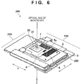
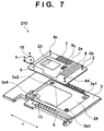
- Fig. 7 exemplarily shows an arrangement in which the XY glass scale 2s is supported on the upper surface side of the X stage plate 3.
- the arrangement of this embodiment is not limited to this example.
- the stage apparatus 200 can be configured such that the XY glass scale 2s is supported on the lower surface side of the X stage plate 3 through the XY scale plate 2.
- the X-direction sensor and the Y-direction sensor are arranged on the microscope base stand 121 at, for example, positions below the XY glass scale 2s.
- the controller 501 can perform position control to position the stage apparatus 200 with respect to an observation target 21 in the slide glass 20 based on the information of the reference position S 0 and the obtained information of the relative position. Position control by the stage apparatus 200 makes it possible to easily reproduce an observation position (the position of the observation target 21 in the slide glass 20) when performing morphological diagnosis, functional diagnosis, and capturing an evidence image with a digital camera in pathological diagnosis.
- Patterns are produced on the XY crosshatch 6, the X-direction scale 8, and the Y-direction scale 7 on the XY glass scale 2s by using a nanotechnology using a semiconductor exposure apparatus.
- the X-direction scale 8 formed from a set of lines in the Y-axis direction and the Y-direction scale 7 formed from a set of lines in the X-axis direction are integrally produced on a silica glass substrate with, for example, an accuracy of 5 nm to 10 nm by a nanotechnology.
- the XY crosshatch 6, the X-direction scale 8, and the Y-direction scale 7 can also be produced by drawing with an exposure apparatus. However, in order to implement low cost production, nano-imprinting can also be used.
- the ratio of a change in length to an increase in temperature is a linear expansion rate (linear expansion coefficient).
- a linear expansion coefficient ⁇ is defined as the rate of change in length with respect to temperature per unit length.
- the linear expansion coefficient ⁇ is defined by equation (1) described in the first embodiment.
- Letting L 0 be the original length of the object before a change in temperature and L be the length of the object when the temperature has changed by t
- the length L can be expressed by equation (2) described in the first embodiment.
- the X stage plate 3 is formed from, for example, an aluminum alloy to decrease the weight of the moving unit and ensure the rigidity of the stage apparatus.
- a linear expansion coefficient ⁇ 1 of the aluminum alloy is 24 x 10 -6 /°C.
- a pressing force reception member 18 (to be described later) is formed from, for example, an aluminum alloy. Forming the pressing force reception member 18 by using members having the same linear expansion coefficient as that of the X stage plate 3 can inhibit stress caused by relative deformation (length increase/decrease differences) caused by a change in temperature from acting on the XY scale plate 2, thereby suppressing distortion caused in the XY scale plate 2.
- the XY glass scale 2s is formed from glass, for example, silica glass, which is a material having a very small linear expansion coefficient, so as to be used as a reference for the implementation of high-precision observation position management.
- the XY scale plate 2 is formed from a low-expansion alloy, which is a material having a very small linear expansion coefficient, so as to be used as a reference for the implementation of high-precision observation position management.
- Both silica glass and a low-expansion alloy have an equal linear expansion coefficient ⁇ 2, which is about 0.5 x 10 -6 /°C.
- the slide glass 20 fixed on the XY scale plate 2 is made of glass, which has almost the same linear expansion coefficient as that of the XY glass scale 2s and the XY scale plate 2.
- the XY glass scale 2s, the XY scale plate 2, and the slide glass 20 have similar linear expansion coefficients, which are smaller than the linear expansion coefficient of the X stage plate 3. For this reason, relative deformation (length increase/decrease differences) caused by a temperature change have only small influences on the XY glass scale 2s, the XY scale plate 2, and the slide glass 20.
- the following arrangement for holding the XY scale plate 2 on the X stage plate 3 reduces the influence of a relative deformation (length increase/decrease difference) caused by a temperature change in accordance with the difference between the two linear expansion coefficients.
- a stepped portion 25 having a concave shape for the arrangement of the XY scale plate 2 is formed on the upper surface of the X stage plate 3, as shown in Fig. 7 .
- the depth of the concave portion is almost the same as the height (thickness) of the XY scale plate 2. While the XY scale plate 2 is arranged on the stepped portion 25 of the X stage plate 3, the upper surface of the XY scale plate 2 is almost flush with the upper surface of the X stage plate 3.
- a plurality of holding units for holding the XY scale plate 2 are formed on the stepped surface of the stepped portion 25.
- the reference surface of the first holding unit 3a1 and the holding surfaces of the second holding unit 3a2 to the fourth holding unit 3a4 have, for example, circular cross-sectional shapes.
- the height of the first holding unit 3a1 to the fourth holding unit 3a4 is higher than that of the stepped surface of the stepped portion 25.
- Holding the XY scale plate 2 by using the first holding unit 3a1 to the fourth holding unit 3a4 can shorten the length of a portion where the XY scale plate 2 is in contact with the X stage plate 3 as compared with a case in which the XY scale plate 2 is directly mounted on the stepped surface of the stepped portion 25.
- This arrangement can reduce a change in the length of the object caused by a change in temperature.
- reducing a change in the length of the object caused by a change in temperature can hold (fix) the XY scale plate 2 on the X stage plate 3 with high precision without causing stress originating from thermal expansion/contraction in the XY scale plate 2.
- Using such holding structures for the XY scale plate 2 can hold a focus position in the optical axis direction (Z direction) relative to the XY glass scale 2s with high precision.
- Female threaded portions which can be connected to connecting members 4b, 4c, and 4d (male threaded portions) are formed on the holding surfaces of the first holding unit 3a1 to the third holding unit 3a3. Fastening the connecting members 4b, 4c, and 4d (male threaded portions) with the female portions of the first holding unit 3a1 to the third holding unit 3a3 will integrally hold (fix) the XY scale plate 2 on the X stage plate 3 without any backlash.
- An opening portion 13 for holding a pressing member 5 provided on one end of the XY scale plate 2 is formed in the holding surface of the fourth holding unit 3a4.
- the pressing force reception member 18 is arranged so as to cover the pressing member 5 and is fixed on the X stage plate 3 with a connecting member 9 (male threaded portion).
- the pressing force reception member 18 constrains the movement (lift) of the XY scale plate 2 in the Z direction (vertical direction).
- the XY scale plate 2 is supported between the pressing force reception member 18 and the holding surface of the fourth holding unit 3a4 so as to be movable in the X-Y plane.
- Fig. 8A is a view showing the X stage 210 as a component of the stage apparatus 200 when seen from the upper surface side.
- the XY scale plate 2 is held (fixed) on the X stage plate 3 with the connecting members 4b, 4c, and 4d.
- the XY scale plate 2 is pressed against the X stage plate 3 with the biasing forces of the pressing force reception member 18 and the pressing member 5.
- the XY scale plate 2 is supported between the pressing force reception member 18 and the fourth holding unit 3a4 so as to be movable in the X-Y plane.
- the central position of the holding surface (reference surface) of the first holding unit 3a1 of the four holding units (3a1 to 3a4), which is arranged nearest to the reference position S 0 is set as the origin (G in Fig. 8A ) of the X and Y axes on the XY scale plate 2.
- the central position of the holding surface of the first holding unit 3a1 is a reference position in the first and second directions, and the origin G of the X and Y axes coincides with the center of the connecting member 4b.
- the connecting member 4b fixes the XY scale plate 2 on the X stage plate 3 at the origin G of the X and Y axes.
- the center of the holding surface of the second holding unit 3a2 is arranged on the X-axis (first-direction axis) passing through the origin G.
- the center of the holding surface of the third holding unit 3a3 is arranged on the Y-axis (second-direction axis) passing through the origin G and intersecting with the X-axis (first-direction axis).
- the center of the holding surface of the fourth holding unit 3a4 is arranged near a diagonal line with respect to the origin G.
- Fig. 8B is a view showing the cross-sectional structure of the first holding unit 3a1 along the b-b cross-section of Fig. 8A .
- the first holding unit 3a1 holds the XY scale plate 2 (plate member) on the stage plate.
- the XY scale plate 2 is held (fixed) on the X stage plate 3 with the connecting member 4b.
- the XY glass scale 2s is arranged on the XY scale plate 2.
- a hole portion 2b for the insertion of the connecting member 4b is formed in the XY scale plate 2.
- An X stage plate spot facing hole 3b is formed in the holding surface of the first holding unit 3a1 which holds the XY scale plate 2.
- the connecting member 4b is configured to fit in the hole portion 2b and the X stage plate spot facing hole 3b without any backlash. This makes it possible to accurately position the connecting member 4b to the origin G (reference position).
- the connecting member 4b is fastened with the female threaded portion of the first holding unit 3a1 to integrally fix the XY scale plate 2 on the X stage plate 3 at the origin G (reference position).
- Fig. 8C is a view showing the cross-sectional structure of the second holding unit 3a2 along the c-c cross-section of Fig. 8A .
- the second holding unit holds the XY scale plate 2 (plate member) with holding structures whose rigidity in the first direction is lower than that in the second direction.
- the elastic deformation of the holding structures formed on a peripheral portion of the second holding unit absorbs deformation in the first direction caused between the X stage plate 3 and the XY scale plate 2 (plate member) based on a linear expansion coefficient difference.
- the XY scale plate 2 is held (fixed) on the X stage plate 3 with the connecting member 4c.
- the connecting member 4c is fastened with the female threaded portion of the second holding unit 3a2 to integrally fix the XY scale plate 2 on the X stage plate 3.
- a plurality of hole portions are formed in the peripheral portion of the second holding unit 3a2.
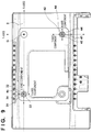
- Fig. 9 is a view showing the structure of the X stage plate 3.
- a plurality of hole portions are formed in the peripheral portion of the second holding unit 3a2.
- the hole portions 31 and 32 are formed on the X-axis (first-direction axis).
- the hole portions 31 and 32 are formed at horizontally symmetrical positions, centered on the position of the second holding unit 3a2.
- the hole portions 33 and 34 are formed in the peripheral portion of the second holding unit 3a2 in the Y-axis (second-direction axis) direction.
- the hole portions 33 and 34 are formed at vertically symmetrical positions, centered on the position of the second holding unit 3a2.
- Fig. 10A is an enlarged view of the peripheral portion of the second holding unit 3a2.
- An elastic holding structure 35 formed between the hole portion 31 and the hole portion 33 functions as a spring structure to connect the X stage plate 3 to the second holding unit 3a2.
- An elastic holding structure 36 formed between the hole portion 32 and the hole portion 33 functions as a spring structure to connect the X stage plate 3 to the second holding unit 3a2.
- An elastic holding structure 37 formed between the hole portion 31 and the hole portion 34 functions as a spring structure to connect the X stage plate 3 to the second holding unit 3a2.
- An elastic holding structure 38 formed between the hole portion 32 and the hole portion 34 functions as a spring structure to connect the X stage plate 3 to the second holding unit 3a2.
- the second holding unit 3a2 is connected to the X stage plate 3 and supported by it with the four elastic holding structures 35 to 38 (spring structures) formed on the peripheral portion.
- Each hole portion functions as a rigidity reducing portion which reduces the rigidity of the X stage plate 3.
- the four elastic holding structures 35 to 38 (spring structures) absorb deformation caused by a reduction in rigidity.
- Forming the hole portions 31 and 32 in the peripheral portion of the second holding unit 3a2 of the X stage plate 3 will reduce the rigidity of the peripheral portion and make the peripheral portion tend to locally deform.
- the peripheral portion of the second holding unit 3a2 of the X stage plate 3 deforms more easily than the peripheral portion of the first holding unit 3a1 in which no hole portion is formed.
- the opening width of the hole portions 31 and 32 in the X-axis direction is larger than that of the hole portions 33 and 34 in the Y-axis direction, and the rigidity of the X-axis component of the peripheral portion of the second holding unit 3a2 is lower than that of the Y-axis component.
- Forming hole portions can provide different rigidities (rigidity anisotropy) in accordance with the respective directions of the X stage plate 3 (X-axis direction, Y-axis direction, and Z-axis direction).
- the structure of the peripheral portion of the second holding unit which is configured to fix the XY scale plate 2 on the X stage plate 3 with the connecting member 4c is formed into a spring structure which tends to deform in the X-axis direction.
- the structure of the peripheral portion of the second holding unit 3a2 can reduce (absorb) deformation (length increase/decrease difference) corresponding to the difference between the X stage plate 3 and the XY scale plate 2 with the four elastic holding structures 35 to 38 (spring structures).
- the connecting member 4c maintains the positional relationship between the X stage plate 3 and the XY scale plate 2 in a fixed state. Absorbing thermal deformation with the spring structures can suppress the occurrence of stress and suppress the occurrence of distortion of the XY scale plate 2 which can be caused by stress.
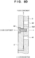
- Fig. 8D is a view showing the cross-sectional structure of the third holding unit 3a3 along the d-d cross-section of Fig. 8A .
- the third holding unit holds the XY scale plate 2 (plate member) with holding structures whose rigidity in the second direction (Y direction) is lower than that in the first direction (X direction).
- the elastic deformation of the holding structures formed on a peripheral portion of the third holding unit absorbs deformation in the second direction (Y direction) caused between the X stage plate 3 and the XY scale plate 2 (plate member) based on a linear expansion coefficient difference.
- the XY scale plate 2 is held (fixed) on the X stage plate 3 with the connecting member 4d.
- the connecting member 4d is fastened with the female threaded portion of the third holding unit 3a3 to integrally fix the XY scale plate 2 on the X stage plate 3.
- a plurality of hole portions are formed in the peripheral portion of the third holding unit 3a3.
- a plurality of hole portions are formed in a peripheral portion of the third holding unit 3a3.
- the hole portions 43 and 44 are formed in the X-axis (first-direction axis) direction.
- the hole portions 43 and 44 are formed at horizontally symmetrical positions, centered on the position of the third holding unit 3a3.
- the hole portions 41 and 42 are formed in the peripheral portion of the third holding unit 3a3 in the Y-axis (second-direction axis) direction.
- the hole portions 41 and 42 are formed at vertically symmetrical positions, centered on the position of the third holding unit 3a3.
- Fig. 10B is an enlarged view of the peripheral portion of the third holding unit 3a3.
- An elastic holding structure 45 formed between the hole portion 41 and the hole portion 43 functions as a spring structure to connect the X stage plate 3 to the third holding unit 3a3.
- An elastic holding structure 47 formed between the hole portion 42 and the hole portion 43 functions as a spring structure to connect the X stage plate 3 to the third holding unit 3a3.
- An elastic holding structure 46 formed between the hole portion 41 and the hole portion 44 functions as a spring structure to connect the X stage plate 3 to the third holding unit 3a3.
- An elastic holding structure 48 formed between the hole portion 42 and the hole portion 44 functions as a spring structure to connect the X stage plate 3 to the third holding unit 3a3.
- the third holding unit 3a3 is connected to the X stage plate 3 and supported by it with the four elastic holding structures 45 to 48 (spring structures) formed on the peripheral portion.
- Each hole portion functions as a rigidity reducing portion which reduces the rigidity of the X stage plate 3.
- the four elastic holding structures 45 to 48 (spring structures) absorb deformation caused by a reduction in rigidity with the elastic deformation of each spring structure.
- Forming the hole portions in the X stage plate 3 will reduce the rigidity of the peripheral portion of the hole portions and make the peripheral portion tend to locally deform. For example, with the formation of the hole portions, the peripheral portion of the third holding unit 3a3 of the X stage plate 3 deforms more easily than the peripheral portion of the first holding unit 3a1 in which no hole portion is formed.
- the opening width of the hole portions 41 and 42 in the Y-axis direction is larger than that of the hole portions 43 and 44 in the X-axis direction, and the rigidity of the Y-axis component of the peripheral portion of the third holding unit 3a3 is lower than that of the X-axis component.
- Forming hole portions can provide different rigidities (rigidity anisotropy) in accordance with the respective directions of the X stage plate 3 (X-axis direction, Y-axis direction, and Z-axis direction).
- the structure of the peripheral portion of the third holding unit which is configured to fix the XY scale plate 2 on the X stage plate 3 with the connecting member 4d is formed into a spring structure which tends to deform in the Y-axis direction.
- the structure of the peripheral portion of the third holding unit 3a3 can reduce (absorb) deformation (length increase/decrease difference) corresponding to the difference between the X stage plate 3 and the XY scale plate 2 with the four elastic holding structures 45 to 48 (spring structures).
- the connecting member 4d maintains the positional relationship between the X stage plate 3 and the XY scale plate 2 in a fixed state. Absorbing thermal deformation with the spring structures can suppress the occurrence of stress and suppress the occurrence of distortion of the XY scale plate 2 which can be caused by stress.
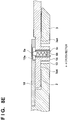
- Fig. 8E is a view showing the e-e cross-section of Fig. 8A , which shows the cross-sectional structure of the fourth holding unit 3a4.
- the end portion of the XY scale plate 2 (plate member) held by the fourth holding unit 3a4 is provided with the pressing member 5 (biasing portion) which generates a biasing force in the third direction (Z direction) intersecting with the first direction (X direction) and the second direction (Y direction).
- the pressing member 5 can be formed as, for example, a ball plunger.
- the pressing member 5 includes an elastic member 5b (compression spring) which generates a biasing force against the upper surface of the X stage plate 3 in the vertical direction, a housing 5c which holds the elastic member 5b, and a spherical member 5a (ball member).
- One end (lower end) of the elastic member 5b (compression spring) is fixed to the housing 5c.
- the other end (upper end) of the elastic member 5b (compression spring) is connected to the spherical member 5a (ball member).
- a housing fixing portion 14 for fixing the housing 5c is formed on the XY scale plate 2.
- a female threaded portion is formed in the inner circumferential surface of the housing fixing portion 14 and, for example, a male threaded portion is formed on the outer circumferential surface of the housing 5c.
- Engaging the male threaded portion with the female threaded portion can fix the pressing member 5 to the XY scale plate 2.
- the pressing force reception member 18 is fixed on the X stage plate 3, the member 5a (ball member), biased by the elastic member 5b (compression spring); presses the lower surface concave portion 18a of the pressing force reception member 18.
- the pressing force reception member 18 presses the XY scale plate 2 (plate member) downward in the third direction (-Z direction) by a biasing force to constrain the deformation of the XY scale plate 2 (plate member) in the third direction relative to the X stage plate 3.
- a reactive force received by the pressing member 5 upon the pressing operation is transmitted to the XY scale plate 2 to press the XY scale plate 2 against the holding surface of the fourth holding unit 3a4.
- the movement (lift) of the XY scale plate 2 in the Z direction (vertical direction) is constrained by using the biasing force of the elastic member 5b.
- the XY scale plate 2 and the X stage plate 3 can relatively move in the X and Y directions.
- a gap is provided between the opening portion 13 formed in the holding surface of the fourth holding unit 3a4 and the housing fixing portion 14 to allow relative movement of the XY scale plate 2 and the X stage plate 3 in the X and Y directions.
- the movement of the XY scale plate 2 and the X stage plate 3 in the X and Y directions receives rolling resistance caused by point contact between the member 5a (ball member) and the pressing force reception member 18 and the frictional resistance between the XY scale plate 2 and the holding surface of the fourth holding unit 3a4.
- these resistance components are sufficiently small to be neglected.
- the pressing member 5 is configured to use the ball plunger
- the pressing member 5 can be configured to use a leaf spring structure or a magnetic suction force to apply a biasing force to press the XY scale plate 2 against the holding surface of the fourth holding unit 3a4 of the X stage plate 3.
- the fourth holding unit 3a4 has an auxiliary function. For example, if the size of the stage is small and the lift and flipping of the XY scale plate 2 can be neglected, the XY scale plate 2 can be held (fixed) on the X stage plate 3 with the first holding unit 3a1 to the third holding unit 3a3 described above without using the fourth holding unit 3a4.
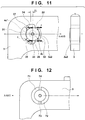
- Fig. 11 is a view exemplarily showing the deformed state of the peripheral portion of the second holding unit 3a2.
- Fig. 11 exemplarily shows a state in which thermal drift has caused relative deformation (length increase/decrease difference ⁇ L: thermal expansion/contraction difference) between the X stage plate 3 and the XY scale plate 2.
- the position of "4c'" indicated by the broken line indicates the position of a connecting member deformed by the length increase/decrease difference ⁇ L between the X stage plate 3 and the XY scale plate 2 when this embodiment is not applied.
- the hole portions 31 to 34 formed in the peripheral portion of the second holding unit 3a2 reduce the rigidity of the peripheral portion of the second holding unit 3a2 in the X direction (first direction) and make the second holding unit 3a2 tend to deform in a plane of the X stage plate 3 in the X direction (first direction).
- the four elastic holding structures 35 to 38 (spring structures) formed in the peripheral portion of the second holding unit 3a2 absorb the length increase/decrease difference ⁇ L caused between the XY scale plate 2 and the X stage plate 3.
- the position of "4c" indicated by the solid line indicates the position of the connecting member according to this embodiment.
- the four elastic holding structures 35 to 38 (spring structures) absorb the length increase/decrease difference ⁇ L which can be caused between the XY scale plate 2 and the X stage plate 3 by a change in temperature.
- the position of "4c"' indicated by the broken line returns by ⁇ L to the right side on the drawing surface in conformity with the position of the hole in the XY scale plate 2 in which the connecting member 4c is inserted.
- the opening width of the hole portion 31 formed on the left side of the peripheral portion of the second holding unit 3a2 increases.
- H0 the initial opening width of the hole portion
- H1 the opening width of the hole portion 31 after deformation
- H1 H0 + ⁇ L
- H2 the opening width of the hole portion 32 formed on the right side of the peripheral portion of the second holding unit 3a2
- Spring forces F (elastic forces) of the four elastic holding structures 35 to 38 (spring structures) for causing deformation corresponding to ⁇ L act symmetrically with respect to the X-axis because the hole portions 31 to 34 are formed horizontally and vertically symmetrically, centered on the second holding unit 3a2. Owing to the action of the spring forces F (elastic forces), the connecting member 4c always deforms on the X-axis. Since the spring forces F (elastic forces) of the four elastic holding structures 35 to 38 (spring structures) act symmetrically with respect to the X-axis, they generate no rotational force to rotate the XY scale plate 2 around the XY origin G.
- Fig. 11 exemplarily shows the second holding unit 3a2.
- the spring forces (elastic forces) of the four elastic holding structures 45 to 48 (spring structures) of the third holding unit 3a3 act symmetrically with respect to the Y-axis because the hole portions 41 to 44 are formed vertically and horizontally symmetrically, centered on the third holding unit 3a3.
- the connecting member 4d always deforms on the Y-axis. Since the spring forces (elastic forces) of the four elastic holding structures 45 to 48 (spring structures) act symmetrically with respect to the Y-axis, they generate no rotational force to rotate the XY scale plate 2 around the XY origin G.
- b be the width between the hole portion 31 and the hole portion 33 in the elastic holding structures 35 to 38 (spring structures). Also, let b be the widths between the remaining hole portions, for example, between the hole portion 32 and the hole portion 33, between the hole portion 31 and the hole portion 34, and between the hole portion 32 and the hole portion 34.
- h be the thickness of the X stage plate 3. The relation between the thickness h of the X stage plate 3 and the width b between the hole portions is expressed as h >> b.
- the elastic holding structures 35 to 38 reduce the rigidity in the X direction (first direction).
- the rigidity in the Z direction (third direction) (a bending rigidity EI: E is the elastic modulus of the X stage plate 3 and I is the moment of inertial of area) is maintained higher than in the X direction (first direction) without being influenced by the elastic holding structures 35 to 38 (spring structures). That is, the rigidity in the Z direction (third direction) is higher than that in the X direction (first direction). This suppresses the deformation of the X stage plate 3 in the Z direction. That is, the flatness accuracy of the XY glass scale 2s in the Z-axis direction is also guaranteed.
- Figs. 10A and 10B have exemplified the four elastic holding structures 35 to 38 (spring structures) formed on the peripheral portion of the second holding unit 3a2 and the four elastic holding structures 45 to 48 (spring structures) formed on the peripheral portion of the third holding unit 3a3.
- the spring structures are not limited to those described with reference to Figs. 10A and 10B .
- the spring structures may have arrangements shown in Fig. 12 which easily elastically deform in one direction and are integrally formed with the X stage plate 3.
- Fig. 12 exemplarily shows an example of the arrangement of spring structures formed on the peripheral portion of the second holding unit 3a2.
- a plurality of hole portions are formed in the peripheral portion of the second holding unit 3a2.
- the hole portions 71 and 72 are formed on the X-axis (first-direction axis).
- the hole portions 71 and 72 are formed at horizontally symmetrical positions, centered on the position of the second holding unit 3a2.
- An elastic holding structure 73 formed between the hole portion 71 and the hole portion 72 functions as a spring structure to connect the X stage plate 3 to the second holding unit 3a2.
- An elastic holding structure 74 functions as a spring structure to connect the X stage plate 3 to the second holding unit 3a2.
- the second holding unit 3a2 is connected to the X stage plate 3 and supported by it with the two elastic holding structures 73 and 74 formed on the peripheral portion.
- the hole portions 71 and 72 function as rigidity reducing portions which reduce the rigidity of the X stage plate 3.
- the two elastic holding structures 73 and 74 (spring structures) absorb deformation caused by a reduction in rigidity with the elastic deformation of the spring structures.
- Forming the hole portions 71 and 72 in the peripheral portion of the second holding unit 3a2 of the X stage plate 3 will reduce the rigidity of the peripheral portion and make the peripheral portion tend to locally deform.
- the peripheral portion of the second holding unit 3a2 of the X stage plate 3 deforms more easily than the peripheral portion of the first holding unit 3a1 in which no hole portion is formed.
- the rigidity in the Y-axis direction is higher than that in the X-axis direction. Since an arrangement corresponding to the elastic holding structures 73 and 74 is not provided in the X-axis direction, the rigidity in the X-axis direction is lower than that in the Y-axis direction. In the arrangement shown in Fig. 12 as well, the rigidity in the Z-axis direction (third direction) is maintained higher than that in the X direction (first direction) without being influenced by the elastic holding structures 73 and 74 (spring structures).
- the rigidity in the Z direction is higher than that in the X direction, and hence the deformation of the X stage plate 3 in the Z direction is suppressed. That is, the flatness accuracy of the XY glass scale 2s in the Z-axis direction is guaranteed.
- Forming the hole portions 71 and 72 can provide different rigidities (rigidity anisotropy) in accordance with the respective directions of the X stage plate 3 (X-axis direction, Y-axis direction, and Z-axis direction).
- Arranging the hole portions 71 and 72 shown in Fig. 12 symmetrically, for example, centered on the position of the third holding unit 3a3 can provide similar spring structures on the peripheral portion of the third holding unit 3a3.
- causes of thermal drift include a change in temperature in an environment surrounding the optical microscope, the body temperature of a human body, and heat generation by a motor or a driving shaft. Even if thermal drift occurs in the microscope stage, the spring structures on the peripheral portion of the holding units absorb deformation. This makes it possible to suppress the occurrence of distortion caused in the XY scale plate held by each holding unit.
- the stage apparatus can stably hold the XY scale plate with respect to the XY reference surface without receiving any influence of thermal deformation. This makes it possible to stabilize the focus position of an optical axis (Z direction) vertically intersecting with the XY reference surface of the eyepiece lens of the microscope, thereby preventing image blur caused by defocus.
- the second holding unit arranged on the X-axis is provided with the spring structures which easily deform in the X-axis direction
- the third holding unit arranged on the Y-axis is provided with the spring structures which easily deform in the Y-axis direction, thereby suppressing stress in each holding unit even if thermal expansion differences caused by thermal drift occur.
- stage apparatus including the holding structures for the compact XY scale with stable measurement accuracy can be arranged in the limited space for the objective lens and the condenser lens in the observation position management microscope system.
- Embodiment(s) of the present invention can also be realized by a computer of a system or apparatus that reads out and executes computer executable instructions (e.g., one or more programs) recorded on a storage medium (which may also be referred to more fully as a 'non-transitory computer-readable storage medium') to perform the functions of one or more of the above-described embodiment(s) and/or that includes one or more circuits (e.g., application specific integrated circuit (ASIC)) for performing the functions of one or more of the above-described embodiment(s), and by a method performed by the computer of the system or apparatus by, for example, reading out and executing the computer executable instructions from the storage medium to perform the functions of one or more of the above-described embodiment(s) and/or controlling the one or more circuits to perform the functions of one or more of the above-described embodiment(s).
- computer executable instructions e.g., one or more programs
- a storage medium which may also be referred to more fully as
- the computer may comprise one or more processors (e.g., central processing unit (CPU), micro processing unit (MPU)) and may include a network of separate computers or separate processors to read out and execute the computer executable instructions.
- the computer executable instructions may be provided to the computer, for example, from a network or the storage medium.
- the storage medium may include, for example, one or more of a hard disk, a random-access memory (RAM), a read only memory (ROM), a storage of distributed computing systems, an optical disk (such as a compact disc (CD), digital versatile disc (DVD), or Blu-ray Disc (BD)TM), a flash memory device, a memory card, and the like.
Landscapes
- Physics & Mathematics (AREA)
- Chemical & Material Sciences (AREA)
- Analytical Chemistry (AREA)
- General Physics & Mathematics (AREA)
- Optics & Photonics (AREA)
- Engineering & Computer Science (AREA)
- Multimedia (AREA)
- Microscoopes, Condenser (AREA)
Applications Claiming Priority (2)
| Application Number | Priority Date | Filing Date | Title |
|---|---|---|---|
| JP2015073489A JP6431426B2 (ja) | 2015-03-31 | 2015-03-31 | ステージ装置および顕微鏡 |
| JP2015073490A JP6562680B2 (ja) | 2015-03-31 | 2015-03-31 | ステージ装置 |
Publications (1)
| Publication Number | Publication Date |
|---|---|
| EP3076218A1 true EP3076218A1 (fr) | 2016-10-05 |
Family
ID=55640511
Family Applications (1)
| Application Number | Title | Priority Date | Filing Date |
|---|---|---|---|
| EP16000723.3A Withdrawn EP3076218A1 (fr) | 2015-03-31 | 2016-03-29 | Appareil à platine et microscope |
Country Status (3)
| Country | Link |
|---|---|
| US (1) | US10222603B2 (fr) |
| EP (1) | EP3076218A1 (fr) |
| CN (1) | CN106019551B (fr) |
Families Citing this family (1)
| Publication number | Priority date | Publication date | Assignee | Title |
|---|---|---|---|---|
| CN110794566B (zh) * | 2018-08-01 | 2021-09-07 | 深圳华大生命科学研究院 | 定位装置、光学成像系统及其装配方法 |
Citations (9)
| Publication number | Priority date | Publication date | Assignee | Title |
|---|---|---|---|---|
| EP0126888A1 (fr) * | 1983-05-03 | 1984-12-05 | Dr. Johannes Heidenhain GmbH | Dispositif de mesure |
| DE4212990A1 (de) * | 1992-04-18 | 1993-10-21 | Christoph Schaeffel | Absolutes Zweikoordinatenmeßsystem mit Drehwinkelerfassung |
| DE4406797A1 (de) * | 1994-03-02 | 1995-09-07 | Heidenhain Gmbh Dr Johannes | Positionsmeßeinrichtung |
| EP0736750A2 (fr) * | 1995-04-06 | 1996-10-09 | Dr. Johannes Heidenhain GmbH | Dispositif de mesure de positions |
| EP1731877A1 (fr) * | 2005-06-08 | 2006-12-13 | Dr. Johannes Heidenhain GmbH | Codeur d'un système de mesure. |
| DE102006004898A1 (de) * | 2006-02-03 | 2007-08-09 | Dr. Johannes Heidenhain Gmbh | Abtastsystem einer Positionsmesseinrichtung |
| JP2013007718A (ja) | 2011-06-27 | 2013-01-10 | Mitsutoyo Corp | ガラススケール保持構造、及びガラススケールの保持方法 |
| JP2013064731A (ja) | 2011-09-15 | 2013-04-11 | Dr Johannes Heidenhain Gmbh | 長さ測定システムの取付け装置 |
| WO2014016526A1 (fr) * | 2012-07-27 | 2014-01-30 | Horiba Jobin Yvon Sas | Dispositif et procede de caracterisation d'un echantillon par des mesures localisees |
Family Cites Families (5)
| Publication number | Priority date | Publication date | Assignee | Title |
|---|---|---|---|---|
| DE19530136C1 (de) * | 1995-08-16 | 1997-02-13 | Leica Mikroskopie & Syst | Einrichtung zur Fokusstabilisierung in einem Mikroskop |
| DE112005002465B4 (de) * | 2004-10-08 | 2017-07-06 | Nikon Corp. | Mikroskopsystem |
| GB0821814D0 (en) * | 2008-11-28 | 2009-01-07 | Thomasons Innovations Ltd | A Connector |
| DE102010061167B3 (de) * | 2010-12-10 | 2012-05-31 | Leica Microsystems Cms Gmbh | Mikroskoptisch |
| DE102010061166B3 (de) * | 2010-12-10 | 2012-05-31 | Leica Microsystems Cms Gmbh | Einrichtung und Verfahren zur justierten Anbringung eines Mikroskoptisches an einem Mikroskopstativ |
-
2016
- 2016-03-29 EP EP16000723.3A patent/EP3076218A1/fr not_active Withdrawn
- 2016-03-30 CN CN201610191575.5A patent/CN106019551B/zh active Active
- 2016-03-31 US US15/087,033 patent/US10222603B2/en active Active
Patent Citations (9)
| Publication number | Priority date | Publication date | Assignee | Title |
|---|---|---|---|---|
| EP0126888A1 (fr) * | 1983-05-03 | 1984-12-05 | Dr. Johannes Heidenhain GmbH | Dispositif de mesure |
| DE4212990A1 (de) * | 1992-04-18 | 1993-10-21 | Christoph Schaeffel | Absolutes Zweikoordinatenmeßsystem mit Drehwinkelerfassung |
| DE4406797A1 (de) * | 1994-03-02 | 1995-09-07 | Heidenhain Gmbh Dr Johannes | Positionsmeßeinrichtung |
| EP0736750A2 (fr) * | 1995-04-06 | 1996-10-09 | Dr. Johannes Heidenhain GmbH | Dispositif de mesure de positions |
| EP1731877A1 (fr) * | 2005-06-08 | 2006-12-13 | Dr. Johannes Heidenhain GmbH | Codeur d'un système de mesure. |
| DE102006004898A1 (de) * | 2006-02-03 | 2007-08-09 | Dr. Johannes Heidenhain Gmbh | Abtastsystem einer Positionsmesseinrichtung |
| JP2013007718A (ja) | 2011-06-27 | 2013-01-10 | Mitsutoyo Corp | ガラススケール保持構造、及びガラススケールの保持方法 |
| JP2013064731A (ja) | 2011-09-15 | 2013-04-11 | Dr Johannes Heidenhain Gmbh | 長さ測定システムの取付け装置 |
| WO2014016526A1 (fr) * | 2012-07-27 | 2014-01-30 | Horiba Jobin Yvon Sas | Dispositif et procede de caracterisation d'un echantillon par des mesures localisees |
Also Published As
| Publication number | Publication date |
|---|---|
| US10222603B2 (en) | 2019-03-05 |
| US20160291309A1 (en) | 2016-10-06 |
| CN106019551A (zh) | 2016-10-12 |
| CN106019551B (zh) | 2019-01-04 |
Similar Documents
| Publication | Publication Date | Title |
|---|---|---|
| US20180373015A1 (en) | Microscope system and method of controlling the same | |
| EP3126891B1 (fr) | Mise au point automatique dans un système à plusieurs appareils photo à optiques pliées peu encombrantes | |
| US10732397B2 (en) | Microscope system, control method thereof, and program | |
| US11287632B2 (en) | Microscope system, control method, and program | |
| US10838187B2 (en) | Slide, set of slide and cover glass, and microscope system | |
| US10928620B2 (en) | Microscope system and method of controlling the same | |
| US10725309B2 (en) | Microscope system | |
| US20180348497A1 (en) | Microscope system | |
| US20180267288A1 (en) | Microscope system and control method thereof | |
| JP6746722B2 (ja) | 顕微鏡用スライドガラスの曲面の高さの測算方法及び顕微鏡 | |
| US20120092655A1 (en) | Inspection system utilizing solid immersion lenses | |
| WO2018025606A1 (fr) | Caméra stéréoscopique | |
| US20170261737A1 (en) | Slide and microscope system using the slide | |
| WO2006018946A1 (fr) | Dispositif de mise au point automatique et microscope comprenant ce dispositif | |
| US10222603B2 (en) | Stage apparatus and microscope | |
| JP6431426B2 (ja) | ステージ装置および顕微鏡 | |
| CN109884060B (zh) | 一种用于数字切片扫描仪的精密对焦装置 | |
| JP6562680B2 (ja) | ステージ装置 | |
| US20220066191A1 (en) | Method of preparing a stage for use in a slide imaging apparatus | |
| US20210382259A1 (en) | Positioning system for components of optical systems | |
| Murakami et al. | Real-time high-speed motion blur compensation method using galvanometer mirror for shape sensing of microfabricated objects | |
| Sadeghian et al. | Demonstration of parallel scanning probe microscope for high throughput metrology and inspection | |
| US10371930B2 (en) | Stage apparatus and microscope | |
| WO2016092813A1 (fr) | Adaptateur pour système de microscope, et système de microscope comprenant l'adaptateur | |
| CN209727783U (zh) | 用于数字切片扫描仪的精密对焦装置 |
Legal Events
| Date | Code | Title | Description |
|---|---|---|---|
| PUAI | Public reference made under article 153(3) epc to a published international application that has entered the european phase |
Free format text: ORIGINAL CODE: 0009012 |
|
| AK | Designated contracting states |
Kind code of ref document: A1 Designated state(s): AL AT BE BG CH CY CZ DE DK EE ES FI FR GB GR HR HU IE IS IT LI LT LU LV MC MK MT NL NO PL PT RO RS SE SI SK SM TR |
|
| AX | Request for extension of the european patent |
Extension state: BA ME |
|
| 17P | Request for examination filed |
Effective date: 20170405 |
|
| RBV | Designated contracting states (corrected) |
Designated state(s): AL AT BE BG CH CY CZ DE DK EE ES FI FR GB GR HR HU IE IS IT LI LT LU LV MC MK MT NL NO PL PT RO RS SE SI SK SM TR |
|
| 17Q | First examination report despatched |
Effective date: 20191126 |
|
| STAA | Information on the status of an ep patent application or granted ep patent |
Free format text: STATUS: THE APPLICATION HAS BEEN WITHDRAWN |
|
| 18W | Application withdrawn |
Effective date: 20200428 |