EP3076238A2 - Dispositif de distribution de matériau d'empreinte - Google Patents
Dispositif de distribution de matériau d'empreinte Download PDFInfo
- Publication number
- EP3076238A2 EP3076238A2 EP16000752.2A EP16000752A EP3076238A2 EP 3076238 A2 EP3076238 A2 EP 3076238A2 EP 16000752 A EP16000752 A EP 16000752A EP 3076238 A2 EP3076238 A2 EP 3076238A2
- Authority
- EP
- European Patent Office
- Prior art keywords
- imprint material
- opening
- container section
- discharging device
- imprint
- Prior art date
- Legal status (The legal status is an assumption and is not a legal conclusion. Google has not performed a legal analysis and makes no representation as to the accuracy of the status listed.)
- Granted
Links
Images





Classifications
-
- B—PERFORMING OPERATIONS; TRANSPORTING
- B29—WORKING OF PLASTICS; WORKING OF SUBSTANCES IN A PLASTIC STATE IN GENERAL
- B29C—SHAPING OR JOINING OF PLASTICS; SHAPING OF MATERIAL IN A PLASTIC STATE, NOT OTHERWISE PROVIDED FOR; AFTER-TREATMENT OF THE SHAPED PRODUCTS, e.g. REPAIRING
- B29C43/00—Compression moulding, i.e. applying external pressure to flow the moulding material; Apparatus therefor
- B29C43/32—Component parts, details or accessories; Auxiliary operations
- B29C43/34—Feeding the material to the mould or the compression means
-
- G—PHYSICS
- G03—PHOTOGRAPHY; CINEMATOGRAPHY; ANALOGOUS TECHNIQUES USING WAVES OTHER THAN OPTICAL WAVES; ELECTROGRAPHY; HOLOGRAPHY
- G03F—PHOTOMECHANICAL PRODUCTION OF TEXTURED OR PATTERNED SURFACES, e.g. FOR PRINTING, FOR PROCESSING OF SEMICONDUCTOR DEVICES; MATERIALS THEREFOR; ORIGINALS THEREFOR; APPARATUS SPECIALLY ADAPTED THEREFOR
- G03F7/00—Photomechanical, e.g. photolithographic, production of textured or patterned surfaces, e.g. printing surfaces; Materials therefor, e.g. comprising photoresists; Apparatus specially adapted therefor
- G03F7/16—Coating processes; Apparatus therefor
-
- B—PERFORMING OPERATIONS; TRANSPORTING
- B05—SPRAYING OR ATOMISING IN GENERAL; APPLYING FLUENT MATERIALS TO SURFACES, IN GENERAL
- B05C—APPARATUS FOR APPLYING FLUENT MATERIALS TO SURFACES, IN GENERAL
- B05C5/00—Apparatus in which liquid or other fluent material is projected, poured or allowed to flow on to the surface of the work
- B05C5/02—Apparatus in which liquid or other fluent material is projected, poured or allowed to flow on to the surface of the work the liquid or other fluent material being discharged through an outlet orifice by pressure, e.g. from an outlet device in contact or almost in contact, with the work
-
- B—PERFORMING OPERATIONS; TRANSPORTING
- B29—WORKING OF PLASTICS; WORKING OF SUBSTANCES IN A PLASTIC STATE IN GENERAL
- B29C—SHAPING OR JOINING OF PLASTICS; SHAPING OF MATERIAL IN A PLASTIC STATE, NOT OTHERWISE PROVIDED FOR; AFTER-TREATMENT OF THE SHAPED PRODUCTS, e.g. REPAIRING
- B29C35/00—Heating, cooling or curing, e.g. crosslinking or vulcanising; Apparatus therefor
- B29C35/02—Heating or curing, e.g. crosslinking or vulcanizing during moulding, e.g. in a mould
- B29C35/08—Heating or curing, e.g. crosslinking or vulcanizing during moulding, e.g. in a mould by wave energy or particle radiation
- B29C35/0805—Heating or curing, e.g. crosslinking or vulcanizing during moulding, e.g. in a mould by wave energy or particle radiation using electromagnetic radiation
-
- B—PERFORMING OPERATIONS; TRANSPORTING
- B29—WORKING OF PLASTICS; WORKING OF SUBSTANCES IN A PLASTIC STATE IN GENERAL
- B29C—SHAPING OR JOINING OF PLASTICS; SHAPING OF MATERIAL IN A PLASTIC STATE, NOT OTHERWISE PROVIDED FOR; AFTER-TREATMENT OF THE SHAPED PRODUCTS, e.g. REPAIRING
- B29C43/00—Compression moulding, i.e. applying external pressure to flow the moulding material; Apparatus therefor
- B29C43/02—Compression moulding, i.e. applying external pressure to flow the moulding material; Apparatus therefor of articles of definite length, i.e. discrete articles
-
- G—PHYSICS
- G03—PHOTOGRAPHY; CINEMATOGRAPHY; ANALOGOUS TECHNIQUES USING WAVES OTHER THAN OPTICAL WAVES; ELECTROGRAPHY; HOLOGRAPHY
- G03F—PHOTOMECHANICAL PRODUCTION OF TEXTURED OR PATTERNED SURFACES, e.g. FOR PRINTING, FOR PROCESSING OF SEMICONDUCTOR DEVICES; MATERIALS THEREFOR; ORIGINALS THEREFOR; APPARATUS SPECIALLY ADAPTED THEREFOR
- G03F7/00—Photomechanical, e.g. photolithographic, production of textured or patterned surfaces, e.g. printing surfaces; Materials therefor, e.g. comprising photoresists; Apparatus specially adapted therefor
- G03F7/0002—Lithographic processes using patterning methods other than those involving the exposure to radiation, e.g. by stamping
-
- G—PHYSICS
- G03—PHOTOGRAPHY; CINEMATOGRAPHY; ANALOGOUS TECHNIQUES USING WAVES OTHER THAN OPTICAL WAVES; ELECTROGRAPHY; HOLOGRAPHY
- G03F—PHOTOMECHANICAL PRODUCTION OF TEXTURED OR PATTERNED SURFACES, e.g. FOR PRINTING, FOR PROCESSING OF SEMICONDUCTOR DEVICES; MATERIALS THEREFOR; ORIGINALS THEREFOR; APPARATUS SPECIALLY ADAPTED THEREFOR
- G03F9/00—Registration or positioning of originals, masks, frames, photographic sheets or textured or patterned surfaces, e.g. automatically
- G03F9/70—Registration or positioning of originals, masks, frames, photographic sheets or textured or patterned surfaces, e.g. automatically for microlithography
- G03F9/7003—Alignment type or strategy, e.g. leveling, global alignment
- G03F9/7042—Alignment for lithographic apparatus using patterning methods other than those involving the exposure to radiation, e.g. by stamping or imprinting
-
- H—ELECTRICITY
- H10—SEMICONDUCTOR DEVICES; ELECTRIC SOLID-STATE DEVICES NOT OTHERWISE PROVIDED FOR
- H10P—GENERIC PROCESSES OR APPARATUS FOR THE MANUFACTURE OR TREATMENT OF DEVICES COVERED BY CLASS H10
- H10P76/00—Manufacture or treatment of masks on semiconductor bodies, e.g. by lithography or photolithography
-
- B—PERFORMING OPERATIONS; TRANSPORTING
- B29—WORKING OF PLASTICS; WORKING OF SUBSTANCES IN A PLASTIC STATE IN GENERAL
- B29C—SHAPING OR JOINING OF PLASTICS; SHAPING OF MATERIAL IN A PLASTIC STATE, NOT OTHERWISE PROVIDED FOR; AFTER-TREATMENT OF THE SHAPED PRODUCTS, e.g. REPAIRING
- B29C35/00—Heating, cooling or curing, e.g. crosslinking or vulcanising; Apparatus therefor
- B29C35/02—Heating or curing, e.g. crosslinking or vulcanizing during moulding, e.g. in a mould
- B29C35/08—Heating or curing, e.g. crosslinking or vulcanizing during moulding, e.g. in a mould by wave energy or particle radiation
- B29C35/0805—Heating or curing, e.g. crosslinking or vulcanizing during moulding, e.g. in a mould by wave energy or particle radiation using electromagnetic radiation
- B29C2035/0827—Heating or curing, e.g. crosslinking or vulcanizing during moulding, e.g. in a mould by wave energy or particle radiation using electromagnetic radiation using UV radiation
-
- B—PERFORMING OPERATIONS; TRANSPORTING
- B29—WORKING OF PLASTICS; WORKING OF SUBSTANCES IN A PLASTIC STATE IN GENERAL
- B29C—SHAPING OR JOINING OF PLASTICS; SHAPING OF MATERIAL IN A PLASTIC STATE, NOT OTHERWISE PROVIDED FOR; AFTER-TREATMENT OF THE SHAPED PRODUCTS, e.g. REPAIRING
- B29C43/00—Compression moulding, i.e. applying external pressure to flow the moulding material; Apparatus therefor
- B29C43/32—Component parts, details or accessories; Auxiliary operations
- B29C43/34—Feeding the material to the mould or the compression means
- B29C2043/3433—Feeding the material to the mould or the compression means using dispensing heads, e.g. extruders, placed over or apart from the moulds
-
- B—PERFORMING OPERATIONS; TRANSPORTING
- B29—WORKING OF PLASTICS; WORKING OF SUBSTANCES IN A PLASTIC STATE IN GENERAL
- B29L—INDEXING SCHEME ASSOCIATED WITH SUBCLASS B29C, RELATING TO PARTICULAR ARTICLES
- B29L2031/00—Other particular articles
- B29L2031/34—Electrical apparatus, e.g. sparking plugs or parts thereof
Definitions
- the present invention relates to an imprint material discharging device that discharges an imprint material.
- a so-called imprint technique in which, in a process for manufacturing, for example, a semiconductor device, a mold having a pattern is brought into contact with an imprint material on a substrate and the shape of the mold is transferred to the imprint material to form a pattern thereon, is known.
- an imprint material discharging device that discharges an imprint material onto a substrate
- a discharging device using an inkjet head is described in Japanese Patent Laid-Open No. 2014-216471 .
- the inkjet head of the discharging device that is described in Japanese Patent Laid-Open No. 2014-216471 includes energy generating elements that generate energy for discharging the imprint material onto the substrate.
- a proper pattern may not be formed when the mold is brought into contact with the imprint material. Therefore, in the discharging device that is described in Japanese Patent Laid-Open No. 2014-216471 , the imprint material from which the foreign substance has been removed by a filter is supplied to a container section.
- the present invention in its first aspect provides an imprint material discharging device as specified in claims 1 to 22.
- the present invention in its second aspect provides an imprint apparatus as specified in claims 23 to 25.
- the size of any foreign substance that is produced in the imprint material container section as mentioned above is approximately a few tens of nm, which is small.
- the channel resistance (pressure loss) in the filter may slow down the supply of the imprint material to a discharging member, or may influence the discharge of the imprint material.
- the present invention provides an imprint material discharging device that is capable of properly discharging an imprint material from a discharging member while properly removing any foreign substance that is produced in the imprint material in a container section by using a filter.
- Fig. 1 illustrates a structure of an imprint apparatus 100.
- an apparatus that cures an ultraviolet curable resin, used as an imprint material, by irradiating it with ultraviolet light is exemplified.
- the imprint material and the curing method are not limited thereto.
- a photo-curable resin may be cured by irradiating it with light having wavelengths other than those of ultraviolet light by using a light irradiation device, or a thermosetting resin may be cured with heat.
- the imprint apparatus 100 shown in Fig. 1 includes an imprint material discharging device 10 and a mold 1.
- the imprint apparatus 100 including the mold 1 and the imprint material discharging device 10 may be separately provided. That is, the imprint material may be discharged by the imprint material discharging device 10, and the mold of the imprint apparatus 100 that is provided separately from the imprint material discharging device 10 may be used to perform imprinting.
- the imprint material discharging device 10 includes an imprint material discharging member 11, a container member 12 including a container section 15 for containing the imprint material, and a pressure control member 13.
- a substrate 4 is provided on a stage 6.
- An imprint material 8 is discharged onto the substrate 4 from the discharging member 11.
- the mold 1 is brought into contact with the imprint material 8 that has been discharged onto the substrate.
- the imprint material 8 is irradiated with ultraviolet light emitted from an ultraviolet light irradiation device 7, and is cured.
- a fine irregular pattern or the like is formed in the mold 1.
- the imprint material is in a state in which the pattern of the mold has been transferred to the imprint material. In this way, the pattern is formed on the imprint material.
- the stage 6 is movable along a base frame 5 while the stage 6 holds the substrate 4.
- a mold driving mechanism 2 that vertically drives the mold 1 is held by a structure 3.
- the mold driving mechanism 2 is capable of bringing the mold 1 towards the substrate 4, and bringing the mold 1 into contact with the imprint material 8.
- the ultraviolet light irradiation device 7 exists above the mold 1, and irradiates the imprint material 8 with ultraviolet light 9 via the mold 1.
- the ultraviolet light 9 may be generated from, for example, a light source such as a halogen lamp that generates an i-line and a g-line.
- the ultraviolet light irradiation device 7 may have a function of condensing light generated from the light source.
- the substrate 4 is placed on the stage 6.
- the stage 6 moves the substrate 4 to a location that is underneath the discharging member 11 of the imprint material discharging device 10. While moving the stage 6, the imprint material 8 is discharged onto the substrate 4 from the discharging member 11.
- the stage 6 moves a portion of the substrate 4 onto which the imprint material 8 has been discharged to a location that is underneath the mold 1. Further, the mold driving mechanism 2 lowers the mold 1, and brings the mold 1 close to the substrate 4. In this state, an alignment scope or the like causes an alignment mark on the mold 1 and an alignment mark on the substrate to overlap, so that the position of the mold 1 and the position of the substrate 4 are aligned relative to each other.
- the mold driving mechanism 2 moves the mold 1 further downward (in the direction of the substrate 4), and causes the mold 1 to contact the imprint material 8.
- the ultraviolet light irradiation device 7 emits the ultraviolet light 9, and applies the ultraviolet light 9 transmitted through the mold 1 to the imprint material 8.
- a photo-curing reaction occurs in the imprint material 8, so that the imprint material 8 is cured.
- the mold driving mechanism 2 separates the mold 1 from the cured imprinted material 8.
- a pattern on the substrate 4 that is, a patterned imprint material.
- the imprint apparatus that is used in manufacturing a semiconductor may be used to form a pattern over the entire region of the substrate 4. In such a case, the imprint operation is repeated with respect to the substrate while changing the regions of the substrate on which the imprint operation is performed.
- Fig. 2 is a schematic view of the imprint material discharging device 10.
- the imprint material discharging device 10 primarily includes the discharging member 11, the container member 12, and the pressure control member 13.
- a separation membrane 14 that separates a space in the container section is provided in the container member 12.
- the separation membrane 14 is a membrane that separates the imprint material and a filling liquid (described below), and is desirably flexible. It is desirable that the thickness of the separation membrane 14 be from 10 ⁇ m to 200 ⁇ m. It is desirable that the separation membrane 14 be made of a liquid or a gaseous material having low transmissivity. For example, the separation membrane 14 may be formed from an aluminum multilayer film.
- the discharging member 11 includes energy generating elements 29 that generate energy for discharging the imprint material.
- the discharging member 11 is shown in enlarged form in Fig. 3 .
- the discharging member 11 has a discharge port 32 for discharging the imprint material, and a region 33 that is formed between each energy generating element 29 and the discharge port 32.
- Examples of the energy generating elements 29 include piezoelectric elements and heat generating resistors. Since materials that contain a large amount of resin are frequently used as the imprint material, it is desirable to use piezoelectric elements as the energy generating elements.
- the imprint material 8 in the region 33 between each energy generating element 29 and the discharge port 32 is discharged onto the substrate from the discharge port 32.
- the discharging member 11 be a liquid discharging head that is used for, for example, an inkjet head.
- a discharging member that controls the supply of liquid and the stoppage of the supply of liquid by using a control valve or the like may also be used.
- the discharging member 12 includes the container section 15 that contains the imprint material, and a filling liquid section 16 that is a space provided opposite to the container section 15 with the separation membrane 14 disposed therebetween and that is not connected to the discharging member 11.
- the filling liquid section 16 is filled with the filling liquid, and communicates with the pressure control member 13 via a communication portion 17.
- the pressure control member 13 includes, for example, a filling liquid tank, a pipe, a pressure sensor, a pump, and a valve.
- the pressure sensor, the pump, and the valve are used to control the pressure of the filling liquid in the filling liquid section.
- the imprint material in the container section 15 is consumed and is reduced in amount, so that the separation membrane 14 is deformed.
- the filling liquid section 16 is replenished with filling liquid from the filling liquid tank by the pressure control member 13, so that the filling liquid section 16 is filled with the filling liquid.
- the imprint material that is used in the imprint apparatus is required to maintain its properties until the imprint material is applied to the substrate with the amount of foreign substance (number of minute particles) and the number of metallic ions being minimized.
- the imprint material does not contact outside air and equipment such as the pressure sensor, it is possible to suppress the increase of foreign substances and metallic ions that have been initially controlled and sealed in.
- a bag-like flexible membrane which is like an infusion bag, may be used.
- a gas-liquid interface may be formed in the container section 15.
- the container section 15 may be formed into a nonpressure type by connecting an air communication port to the container section 15.
- the container section 15 in order to perform proper negative pressure control, it is desirable that the container section 15 be connected to an on-off valve or a device that controls the pressure.
- the discharging member is designed such that the interior of the discharging member is maintained at a negative pressure in a certain range.
- a method for generating negative pressure by utilizing capillary force in the interior of a porous material that is provided in the container section to retain a liquid is known.
- Other methods include a method for generating negative pressure in the container section by combining a mechanical element, such as a spring, and a balloon-like membrane, and a method for controlling negative pressure by utilizing a control valve and air pressure. Even in the present invention, the negative pressure in the container section may be controlled by such methods.
- the imprint material discharging device has a structure in which a channel connected to the container section is provided outside the container member, and in which a filter is disposed in the channel.
- Fig. 3 illustrates an example of the imprint material discharging device according to the present invention.
- the channel (a channel formation member 28 that forms the channel) is connected to the container section 15 of the container member of the imprint material discharging device.
- the channel formation member 28 is a member in which the imprint material channel is formed, and is connected to the container section 15 through a first opening 20 and a second opening 21 that open into the container section 15.
- the first opening 20 is an opening that allows the imprint material in the container section 15 to be supplied into the channel.
- the second opening 21 is an opening that allows the imprint material supplied from the first opening 20 to be supplied into the container section 15.
- a pump 22 and a filter 23 that filters the imprint material are disposed in the channel that connects the first opening 20 and the second opening 21.
- the filter 23 be disposed downstream from the pump 22 in the direction of flow of the imprint material from the first opening 20 to the second opening 21.
- the pump 22 may be provided outside the channel.
- the imprint material contained in the container section 15 is supplied (sucked) from the first opening 20. After the imprint material supplied from the first opening 20 has passed through and has been filtered by the filter 23 in the channel, the imprint material flows back into the container section 15 through the second opening 21. Then, the imprint material is supplied again from the first opening 20. That is, the imprint material in the container section 15 is circulated and filtered in the filter 23.
- the filter 23 is disposed in the channel that communicates with the container section of the container member instead at a location between the discharging member and the container section of the container member.
- the imprint material supplied from the first opening 20 of the channel is supplied from the second opening 21 without passing through the region 33 between the discharge port and each energy generating element of the discharging member 11.
- the channel of the channel formation member 28 is provided at a portion that differs from the region 33 between the discharge port and each energy generating element.
- the ink print material is properly supplied to the discharging member 11, and is properly discharged from the discharge port 32 of the discharging member 11.
- An example of a structure in which the imprint material is circulated and filtered without passing through the region 33 consists in not disposing the region 33 on a straight line that connects the first opening 20 and the second opening 21 to each other.
- An imprint material discharging device shown in Fig. 13 is shown as a comparative example.
- the imprint material discharging device shown in Fig. 13 includes a filter 18 between the container section 15 of the container member and the discharging member 11, the imprint material discharging device shown in Fig. 13 does not have a channel in which the filter disposed as in the present invention.
- the structure shown in Fig. 13 allows the imprint material to be filtered at a location that is closest to the discharging member, and the filter is interposed between the container member and the discharging member, so that the structure is easily manufactured. From these viewpoints, such a structure is a practical structure.
- the filter that is used in the imprint material discharging device has a small average aperture (that is, a small average opening diameter in the filter), and has a high channel resistance. Therefore, the supply of the imprint material into the discharging member 11 is slowed down, as a result of which the discharge of the imprint material from the discharging member 11 may be influenced.
- the filter is at least required to be a filter having a channel resistance (pressure loss) that is less than that of the filter 23 in the channel, that is, is required to be a filter having an average aperture that is larger than that of the filter 23 in the channel.
- the imprint material discharging device may be in the form of a cartridge that is removable from the imprint apparatus. For example, it is possible to set a state in which imprint can be immediately performed by mounting the imprint material discharging device having the form of a cartridge on the imprint apparatus and replacing the imprint material discharging device having the form of a cartridge after the imprint material in the container section 15 has been completely consumed. It is possible to integrate the pump 22 and the filter 23 with the imprint material discharging device as a cartridge, and replace them at the same time when replacing the imprint material discharging device. Such methods allow the imprint material discharging device to be replaced while minimizing the possibility of foreign substances mixing in the imprint material discharging device.
- the container section 15 may be replaceable. That is, with the container section 15 being separable from the pump 22 and the filter 23, it is possible to replace only the container section 15. Since, for example, the pump 22 and the filter 23 are not replaced, this method is desirable from the viewpoint of costs.
- the channel formation member 28 shown in Fig. 3 has the form of a tube.
- the channel in the channel formation member only needs to be formed outside the container section 15.
- the channel in the channel formation member may be a channel formed in the container member by a cutting operation.
- the pump 22 and the filter 23 may be connected to the container section 15 by, for example, a tube to allow the pump 22 and the filter 23 to be separable through, for example, a removable joint or valve.
- a material having high viscosity may be selected as the imprint material that is used in imprint techniques.
- the discharging device has the form of a cartridge, it is desirable that the pump be small. Therefore, it is desirable that a structure be designed for efficiently filtering the imprint material by the filter 23. Consequently, openings of the channel are provided at the positions shown in Fig. 4 .
- the imprint material discharging device shown in Fig. 4 is such that two openings of the channel that open into the container section are positioned on a diagonal. That is, in the imprint material discharging device shown in Fig. 3 , the first opening 20 and the second opening 21 open in the same side surface of the container section 15.
- the first opening 20 opens in a side surface of the container section 15 and the second opening 21 opens in the top surface of the container section 15. That is, the first opening 20 and the second opening 21 open in different surfaces of the container section 15.
- the first opening 20 and the second opening 21 open in different surfaces of the container section 15.
- a lower surface in the gravitational direction is a bottom surface
- an upper surface in the gravitational direction is a top surface
- surfaces that connect the bottom surface and the top surface are side surfaces (four surfaces if the container section is a cube).
- a material (liquid) having high viscosity has, in particular, low inertial force when it flows, the material flows in a state in which its laminar flow is maintained without being agitated. Therefore, as in the flow denoted by arrows in Fig. 4 , the imprint material supplied from the second opening 21 flows slowly without being spread and without any fluctuations in the container section 15, and is supplied to the first opening 20 while a portion of the imprint material replaces surrounding imprint material.
- a corner 24 where the flow in the container section 15 tends to stagnate be curved (to have a rounded shape) as shown in Fig. 4 .
- Such a shape makes it possible to suppress the stagnation of the imprint material at' the corner 24.
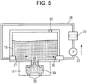
- the first opening 20 and the second opening 21 may be disposed as shown in Fig. 5 . That is, the first opening 20 and the second opening 21 may open in two opposite side surfaces of the container section 15. As shown in Fig. 5 , if, as the imprint material is being consumed, gas (air) enters the container section 15 from an air communication port 25 that communicates with the air, it is desirable that the first opening 20 and the second opening 21 open in portions of side surfaces of the container section 15 that are closer to the bottom surface than to the top surface. By disposing the first opening 20 and the second opening 21 in this way, it is possible to circulate and filter the imprint material just before the liquid is consumed and the container section 15 runs out of the liquid.
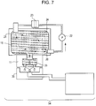
- the imprint material In order to increase the efficiency with which the imprint material is replaced, as mentioned up until now, it is desirable to circulate and discharge the imprint material. More specifically, as shown in Fig. 6A , while circulating the imprint material in the container section 15, the imprint material is caused to flow towards the region 33 and is discharged from the discharge port 32. Since the imprint material flows downward towards the discharging member 11 from the container section 15 by the discharging operation, the flow of the imprint material 15 in the container section 15 when it is circulated and filtered becomes a flow that passes near a communication port between the container section 15 and the discharging member 11.
- the imprint material that is circulated and filtered stagnates in the container section 15, it is possible to change the flow of the imprint material by the discharging operation, and to eliminate the stagnation of the imprint material. As a result, it is possible to increase the efficiency with which the imprint material that is supplied to the region 33 is replaced.
- the pressure control member 13 which is pressure adjusting means, applies pressure to the internal portion of the filling liquid section 16 in the container member 12 through the communication portion 17.
- the pressure control member 13 applies pressure to the internal portion of the filling liquid section 16
- pressure is also applied to the interior of the container section 15 that contains the imprint material through the separation membrane 14.
- the imprint material in the container section 15 passes through the communication port disposed between the container section 15 and the discharging member 11, flows into the region 33 of the discharging member 11, and is discharged from the discharge port 32.
- the amount of imprint material that is discharged from the discharge port 33 may be determined on the basis of at least one of the supply amount and the supply flow rate of the imprint material that is supplied from the first opening 20 to the second opening 21 when the imprint material is circulated and is filtered. That is, the pressure may be adjusted by the pressure adjusting means on the basis of at least one of the supply amount and the supply flow rate of the imprint material that is supplied from the first opening 20 to the second opening 21 when the imprint material is circulated and filtered.
- the discharge amount is determined. In determining the discharge amount, the pressure application time and the pressure value of the pressure application to the internal portion of the container section 15 are also determined.
- a suction controlling member 34 which is sucking means that sucks the imprint material from the discharge port 32.
- the suction controlling member 34 includes, for example, a sucking section, a pipe, a pressure sensor, a valve, and a negative pressure generating section.
- the sucking section of the suction controlling member 34 is disposed below the discharge port 32 during the discharging operation, the negative pressure generating section adjusts the pressure such that a portion that is lower than a top portion of a meniscus surface at the discharge port 32 has a negative pressure through the suction section 35, and the imprint material is discharged.
- the suction amount or the suction flow rate of the imprint material may be determined on the basis of at least one of the supply amount and the supply flow rate of the imprint material that is supplied from the first opening 20 to the second opening 21 when the imprint material is circulated and is filtered. Therefore, information regarding the discharge amount is previously acquired by conducting experiments or the like such that the efficiency with which the imprint material in the container section 15 is replaced becomes a maximum in accordance with the remaining amount of imprint material in the container section 15 and the supply flow rate and the supply time when the imprint material is circulated and filtered. On the basis of the acquired information, the discharge amount is determined. In determining the discharge amount, the suction time and the pressure value at the sucking section are also determined.
- the imprint material may be discharged at the same time that the imprint material is circulated and filtered, or the imprint material may be circulated and filtered and discharged after the imprint material has been circulated and filtered for a specified period of time. Alternatively, the imprint material may be circulated and filtered after previously discharging the amount of imprint material required to replace the imprint material that exists in the region 33.
- a removing operation may be performed for removing the bubbles in the discharge port.
- the imprint material may be circulated and filtered during the removing operation for removing the bubbles. This makes it possible to efficiently replace the imprint material at the region 33 with the filtered imprint material that has been filtered, and to stably discharge imprint material having a small amount of foreign substance and a small number of metallic ions to the substrate.
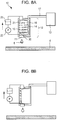
- Figs. 8A and 8B illustrate states of the imprint material discharging device before and after the consumption of the imprint material.
- Fig. 8A illustrates the state before the consumption of the imprint material; and
- Fig. 8B illustrates the state after the consumption of the imprint material.
- the separation membrane 14 divides the interior of the container member 12 into the imprint material container section 15 and the filling liquid section 16. As the imprint material is consumed, the separation membrane 14 is deformed, and the volume of the container section 15 is reduced.
- Air may exist in the container section 15.
- air may be deliberately introduced therein.
- air may become mixed, or gas dissolved in the imprint material may be formed into air bubbles.
- the air that exists in the imprint material is sent to the pump 22 and the filter 23, this may, for example, clog the pump 22 and the filter 23. Therefore, in order to minimize the sucking of the air by the first opening 20, it is desirable that, when the imprint material is being supplied from the first opening 20, the first opening 20 be disposed so as to open at a lower side of the container section in the gravitational direction.
- the first opening 20 open at a location situated below the second opening 21 in the gravitational direction.
- the first opening 20 open at a location of a side surface of the container section 15 that is closer to the bottom surface than to the top surface.
- a trap space 26 which is a recess for trapping the air, in the top surface, which is the upper surface in the gravitational direction, of the container section 15. Since the air accumulates in the trap space 26, even if there is a gentle flow due to the circulation and filtering of the imprint material in the container section 15, it is possible to properly separate the air and the imprint material from each other.
- an air-liquid interface exists in the container section 15.
- the imprint material may bubble or air may mix in the imprint material. Therefore, it is desirable that the second opening 21 open at a location below the top surface of the container section 15 in the gravitational direction and below the air-liquid interface in the gravitational direction to supply the imprint material to the container section 15. Therefore, the second opening 21 may have a protruding shape that protrudes from the top surface of the container section 15, or a tube may be connected to the second opening 21 to guide an end of the tube to a location below the air-liquid interface.
- a channel may be formed through the discharging member 11. Such a structure is shown in Fig. 12 .
- the channel extends from the first opening 20 to the second opening 21 through the interior of the discharging member 11.
- the region 33 is not provided in the channel through which the imprint material passes. That is, the imprint material supplied into the channel from the first opening 20 is supplied to the container section from the second opening 21 without passing through the region 33.
- FIG. 14 An example in which the imprint material supplied into the channel from the first opening 20 is supplied to the container section from the second opening 21 through the region 33 is shown in Fig. 14 .
- a method for initially filling the container section 15 of the imprint material discharging device with the imprint material is described.
- two imprint material filling ports 27 are provided in a side surface of the container section 15, and this side surface, that is, the filling ports 27 face upward in the gravitational direction when filling the container section 15 with the imprint material.
- the imprint material is supplied from one of the two filling ports 27, and air is supplied from the other of the two filling ports 27.
- an internal channel of the pump 22, an internal channel of the filter 23, etc. are also filled with the imprint material to make it less likely for the air to remain in the container section 15.
- the container section 15 when the container section 15 is to be filled with the imprint material, it is desirable to drive the pump 22.
- the pump 22 When the pump 22 is driven, the air that initially exists in the internal channel of the pump 22, the internal channel of the filter 23, etc. is replaced by the imprint material, and exits from the second opening 21. Since the air is supplied from the closest filling port 27, it is possible to fill the channel that includes the container section 15 and the filter 23 without bubbling the imprint material more than necessary.
- the container section may be filled with the imprint material not only at the initial stage but also during use of the imprint apparatus. For example, while filling the container section 15 with the imprint material from the filling port 27, the imprint apparatus may be used.
- the filter 23 is a filter having an average aperture that is too large, it becomes difficult to sufficiently remove foreign substance in the imprint material. Therefore, the filter 23 is, desirably, a filter having an average aperture that is less than or equal to 10 nm, and, more desirably, a filter having an average aperture that is less than or equal to 5 nm. In contrast, when the filter 23 is a filter having an average aperture that is too small, it becomes difficult to circulate the imprint material in the channel due to pressure loss at the filter. Therefore, it is desirable that the filter 23 be a filter having an average aperture that is greater than or equal to 2 nm.
- the filter 23 When the amount of foreign substance that exists in the imprint material is large, the filter may be clogged for a short period of time. Therefore, it is also desirable for the filter 23 to have a multiple filter structure in which, as a pre-filter, a filter that removes a large foreign substance is disposed on the upstream side in the direction of circulation, and a filter that removes a small foreign substance on the downstream side in the direction of circulation.
- the filter that removes a large foreign substance is, for example, a filter having an average aperture in the range of 50 nm to 200 nm.
- the filter that removes a small foreign substance is, for example, a filter having an average aperture in the range of 2 nm to 10 nm.
- the filter 23 be of a membrane type or a hollow fiber membrane type.
- Such filters each include a plurality of fine holes in a membrane by which foreign substances are filtered and do not allow foreign substances having sizes that are greater than or equal to the aperture to pass therethrough.
- materials of which the filter is made include polyethylene, fluororesin, and nylon.
- the amount of metal that exists in the imprint material is required to be very small. Therefore, it is desirable to use a filter that absorbs the metal and that performs ion exchange. It is desirable that a plurality of such filters be disposed in series or in parallel.
- the pump 22 for example, a diaphragm pump, a syringe pump, a tube pump, or a gear pump may be used. It is desirable that the feeding flow rate of the pump 22 be less than or equal to 100 mL/min. When the flow rate is increased, the channel resistance (pressure loss) for passing the imprint material through the filter is increased. Therefore, the pump needs to be a high-output pump. Therefore, by using a pump having a feeding flow rate that is less than or equal to 20 mL/min, it is possible to reduce the size of the pump.
- the imprint material discharging device includes a controller. Since control is performed such that a certain flow rate is maintained to feed a liquid, when the filter 23 is clogged and the channel resistance is increased, driving voltage is increased. Therefore, when, at the controller, the driving voltage of the pump is monitored at all times, and the driving voltage exceeds a certain value, a warning that urges a user to replace the filter can be issued to the imprint apparatus.
- the filter 23 is integrated into the imprint material discharging device having the form of a cartridge, the user can immediately use the imprint apparatus by replacing the imprint material discharging device.
- a sensor that monitors the states thereof may be provided, or, for example, a pressure sensor or a flow rate sensor may be formed in a pipe.
- the imprint material discharging device is required to discharge very precise amounts of imprint material onto very precise landing locations on the substrate. Therefore, the shape of the meniscus at the discharge port of the discharging member needs to be stably maintained.
- the pressure of the imprint material may vary as a result of the driving of the pump 22. Therefore, it is desirable that the driving of the pump 22 be stopped while the imprint material is being discharged from the imprint material discharging device.
- the imprint step a pattern is formed on each region on the substrate while the discharge of the imprint material onto the substrate, the contacting of the mold from the imprint material, exposure, and the separation of the mold are repeated. Therefore, it is desirable that the imprint material be circulated and filtered at the container section 15 at a timing other than when the imprint material is being discharged onto the substrate.
- the timing at which the imprint material is circulated and filtered may be a timing at which the substrate or a lot is replaced.
- the imprint material may be circulated and filtered when the amount of foreign substances, such as particles and gels, is increased in the container section 15. Therefore, the imprint material may be circulated and filtered when the apparatus is not operating. It is possible to stop the pump 22 when the imprint step is being executed, and circulate and filter the imprint material during maintenance of the apparatus or during a period of time in which a substrate on which an imprint operation is to be performed does not exist. It is possible to provide the imprint apparatus or the discharging device with a timer function, and circulate and filter the imprint material when a certain time has elapsed. It is also possible to control the pump 22 on the basis of a programmed instruction from the imprint apparatus or the discharging device, or perform a method in which the pump 22 is driven by a user.
- Fig. 11 illustrates the imprint apparatus including a moving mechanism 30 for moving the container section.
- the container member 12 can be moved between a location where the imprint material is discharged and a location where maintenance is performed. It is desirable that a receiving pan 31 that receives the imprint material that has come out from the discharging member 11 to be disposed at the location where maintenance is performed.
- the imprint material When the imprint material is circulated and filtered by causing the moving mechanism 30 to move the container member 12 to the location where maintenance is performed, even if the imprint material has leaked from the discharging member 11 due to large pressure variations, the imprint material can be received by the receiving pan 31. This is effective, for example, when one wants to return the process to the imprint step by quickly ending the circulation and filtering of the imprint material as a result of increasing the circulation and filtering flow rate by increasing the output of the pump 22.
- the timing at which the imprint material is circulated and filtered may be determined in accordance with, for example, the time that has elapsed from the start of use of the imprint material discharging device of the imprint apparatus, the amount of use of the imprint material, the time that has elapsed from the previous circulation and filtering of the imprint material, and the storage environment history of the imprint material discharging device. Since the degree of gelation depends upon the environment and the type of imprint material, the degree of gelation may be determined on the basis of the type of imprint material.
- the amount of imprint material that is circulated and filtered may be reduced, or conditions, such as the circulation and filtering timing and the flow rate, may be changed in accordance with the remaining amount of imprint material in the container section.
- the pump 22 may be intermittently operated. When the pump 22 is controlled and driven at all times at a low flow rate, it is possible to suppress pressure variations. When a diaphragm pump is used as the pump 22, it is possible to, by reducing the vibration width of the diaphragm, suppress pressure variations and circulate and filter the imprint material at all times.
Landscapes
- Physics & Mathematics (AREA)
- General Physics & Mathematics (AREA)
- Engineering & Computer Science (AREA)
- Mechanical Engineering (AREA)
- Health & Medical Sciences (AREA)
- Coating Apparatus (AREA)
- Electromagnetism (AREA)
- Toxicology (AREA)
- Oral & Maxillofacial Surgery (AREA)
- Thermal Sciences (AREA)
- Exposure Of Semiconductors, Excluding Electron Or Ion Beam Exposure (AREA)
- Physical Or Chemical Processes And Apparatus (AREA)
Applications Claiming Priority (2)
| Application Number | Priority Date | Filing Date | Title |
|---|---|---|---|
| JP2015076992 | 2015-04-03 | ||
| JP2016002753A JP6700794B2 (ja) | 2015-04-03 | 2016-01-08 | インプリント材吐出装置 |
Publications (3)
| Publication Number | Publication Date |
|---|---|
| EP3076238A2 true EP3076238A2 (fr) | 2016-10-05 |
| EP3076238A3 EP3076238A3 (fr) | 2017-03-08 |
| EP3076238B1 EP3076238B1 (fr) | 2018-08-29 |
Family
ID=56080210
Family Applications (1)
| Application Number | Title | Priority Date | Filing Date |
|---|---|---|---|
| EP16000752.2A Active EP3076238B1 (fr) | 2015-04-03 | 2016-03-31 | Dispositif de distribution de matériau d'empreinte |
Country Status (4)
| Country | Link |
|---|---|
| US (1) | US20160288378A1 (fr) |
| EP (1) | EP3076238B1 (fr) |
| KR (1) | KR101986877B1 (fr) |
| MY (1) | MY177437A (fr) |
Families Citing this family (8)
| Publication number | Priority date | Publication date | Assignee | Title |
|---|---|---|---|---|
| JP6400090B2 (ja) * | 2014-05-29 | 2018-10-03 | キヤノン株式会社 | 塗布装置、インプリント装置および物品の製造方法 |
| JP6329437B2 (ja) * | 2014-06-10 | 2018-05-23 | キヤノン株式会社 | インプリント装置、インプリント方法、および物品の製造方法 |
| JP6821414B2 (ja) * | 2016-12-13 | 2021-01-27 | キヤノン株式会社 | インプリント装置、及び物品の製造方法 |
| US10421283B2 (en) | 2017-09-06 | 2019-09-24 | Canon Kabushiki Kaisha | Ejection material receiving unit, ejection material ejecting apparatus, and manufacturing method of flexible member |
| JP2019125619A (ja) * | 2018-01-12 | 2019-07-25 | キヤノン株式会社 | 吐出装置およびインプリント装置 |
| JP7077027B2 (ja) * | 2018-01-15 | 2022-05-30 | キヤノン株式会社 | 吐出材吐出装置およびインプリント装置 |
| US10894420B2 (en) | 2018-04-11 | 2021-01-19 | Canon Kabushiki Kaisha | Ejection-material injecting method, ejection-material ejection apparatus, and imprinting apparatus |
| JP7277127B2 (ja) * | 2018-04-11 | 2023-05-18 | キヤノン株式会社 | 吐出材充填方法、吐出材吐出装置、およびインプリント装置 |
Citations (1)
| Publication number | Priority date | Publication date | Assignee | Title |
|---|---|---|---|---|
| JP2014216471A (ja) | 2013-04-25 | 2014-11-17 | 大日本印刷株式会社 | インプリント装置及びインプリント方法 |
Family Cites Families (18)
| Publication number | Priority date | Publication date | Assignee | Title |
|---|---|---|---|---|
| JP2002062667A (ja) * | 2000-08-23 | 2002-02-28 | Sumitomo Chem Co Ltd | 微粒子量の低減されたフォトレジスト組成物の製造方法 |
| US6740163B1 (en) * | 2001-06-15 | 2004-05-25 | Seagate Technology Llc | Photoresist recirculation and viscosity control for dip coating applications |
| US6854836B2 (en) * | 2001-10-05 | 2005-02-15 | Canon Kabushiki Kaisha | Liquid container, liquid supply system, liquid using apparatus, ink tank, ink supply system, inkjet print head and print apparatus |
| TWI362059B (en) * | 2004-11-25 | 2012-04-11 | Az Electronic Mat Ip Japan Kk | Photoresist coating solution supply system and method for supplying photoresist coating solution using thereof, and photoresist coating system using thereof |
| US7854873B2 (en) * | 2005-06-10 | 2010-12-21 | Obducat Ab | Imprint stamp comprising cyclic olefin copolymer |
| US8864296B2 (en) * | 2008-01-30 | 2014-10-21 | Hewlett-Packard Development Company, L.P. | System for priming a fluid dispenser by expanding gas bubbles |
| JP5209431B2 (ja) * | 2008-09-30 | 2013-06-12 | 富士フイルム株式会社 | インクジェット記録装置 |
| US20100102471A1 (en) * | 2008-10-24 | 2010-04-29 | Molecular Imprints, Inc. | Fluid transport and dispensing |
| US20100101493A1 (en) * | 2008-10-27 | 2010-04-29 | Molecular Imprints, Inc. | Dispense System |
| JP5277506B2 (ja) * | 2009-02-09 | 2013-08-28 | キヤノンファインテック株式会社 | インクジェット記録ヘッド、インク貯留装置 |
| JP5739185B2 (ja) * | 2011-02-15 | 2015-06-24 | 富士フイルム株式会社 | インプリント用硬化性組成物の製造方法 |
| JP2013022491A (ja) * | 2011-07-19 | 2013-02-04 | Seiko Epson Corp | 描画装置 |
| JP2013118952A (ja) * | 2011-12-07 | 2013-06-17 | Dainippon Printing Co Ltd | 噴霧デバイス用の液体カートリッジ、液体カートリッジパッケージ、噴霧デバイス及び噴霧デバイス用のメッシュ付容器 |
| US9887095B2 (en) * | 2013-03-12 | 2018-02-06 | Taiwan Semiconductor Manufacturing Company, Ltd. | System and method for an etch process with silicon concentration control |
| JP6280742B2 (ja) * | 2013-12-27 | 2018-02-14 | 東芝テック株式会社 | 液体循環装置、液体吐出記録装置、および液体循環方法 |
| JP6264888B2 (ja) * | 2014-01-07 | 2018-01-24 | セイコーエプソン株式会社 | 液体噴射装置 |
| EP3000602B1 (fr) * | 2014-09-26 | 2020-07-22 | Agfa Nv | Procédé d'éjection à viscosité élevée |
| US20160193785A1 (en) * | 2015-01-02 | 2016-07-07 | Voxel8, Inc. | 3d printer for printing a plurality of material types |
-
2016
- 2016-03-28 US US15/083,028 patent/US20160288378A1/en not_active Abandoned
- 2016-03-31 MY MYPI2016000579A patent/MY177437A/en unknown
- 2016-03-31 EP EP16000752.2A patent/EP3076238B1/fr active Active
- 2016-04-01 KR KR1020160040231A patent/KR101986877B1/ko active Active
Patent Citations (1)
| Publication number | Priority date | Publication date | Assignee | Title |
|---|---|---|---|---|
| JP2014216471A (ja) | 2013-04-25 | 2014-11-17 | 大日本印刷株式会社 | インプリント装置及びインプリント方法 |
Also Published As
| Publication number | Publication date |
|---|---|
| KR20160118978A (ko) | 2016-10-12 |
| EP3076238A3 (fr) | 2017-03-08 |
| EP3076238B1 (fr) | 2018-08-29 |
| US20160288378A1 (en) | 2016-10-06 |
| MY177437A (en) | 2020-09-15 |
| KR101986877B1 (ko) | 2019-06-07 |
Similar Documents
| Publication | Publication Date | Title |
|---|---|---|
| EP3076238B1 (fr) | Dispositif de distribution de matériau d'empreinte | |
| JP6882574B2 (ja) | インプリント材吐出装置 | |
| CN110356111B (zh) | 喷射材料注入方法、喷射材料喷射装置和压印装置 | |
| CN109130513B (zh) | 液体喷射装置、液体喷射装置的填充方法 | |
| KR20160118941A (ko) | 액체 토출 장치, 임프린트 장치 및 부품 제조 방법 | |
| CN109484025B (zh) | 液体喷出装置及液体喷出装置的控制方法 | |
| CN109484026B (zh) | 液体喷出装置及液体喷出装置的控制方法 | |
| TWI613095B (zh) | 排液設備,壓印設備及製造構件的方法 | |
| US20110193920A1 (en) | Liquid ejecting apparatus, and nozzle recovery method used in liquid ejecting apparatus | |
| CN112793304A (zh) | 液体喷射装置、液体喷射装置的维护方法 | |
| US11520227B2 (en) | Ejection material filling device, pressure regulation device, and ejection material filling method | |
| US11143956B2 (en) | Ejection device and imprint apparatus | |
| JP2019051635A (ja) | 液体噴射装置、液体噴射装置の液体排出方法 | |
| JP7277127B2 (ja) | 吐出材充填方法、吐出材吐出装置、およびインプリント装置 | |
| US10406731B2 (en) | Application device, imprinting apparatus, and method for manufacturing object | |
| US12441122B2 (en) | Liquid discharge apparatus and imprint apparatus | |
| JP7792778B2 (ja) | 液体吐出装置及びインプリント装置 | |
| JP7600697B2 (ja) | 液体循環装置、液体吐出装置、及び液体吐出装置の気泡排出方法 | |
| JP2018006470A (ja) | インプリント材吐出装置 | |
| JP2018006469A (ja) | インプリント材吐出装置 |
Legal Events
| Date | Code | Title | Description |
|---|---|---|---|
| PUAI | Public reference made under article 153(3) epc to a published international application that has entered the european phase |
Free format text: ORIGINAL CODE: 0009012 |
|
| AK | Designated contracting states |
Kind code of ref document: A2 Designated state(s): AL AT BE BG CH CY CZ DE DK EE ES FI FR GB GR HR HU IE IS IT LI LT LU LV MC MK MT NL NO PL PT RO RS SE SI SK SM TR |
|
| AX | Request for extension of the european patent |
Extension state: BA ME |
|
| PUAL | Search report despatched |
Free format text: ORIGINAL CODE: 0009013 |
|
| AK | Designated contracting states |
Kind code of ref document: A3 Designated state(s): AL AT BE BG CH CY CZ DE DK EE ES FI FR GB GR HR HU IE IS IT LI LT LU LV MC MK MT NL NO PL PT RO RS SE SI SK SM TR |
|
| AX | Request for extension of the european patent |
Extension state: BA ME |
|
| RIC1 | Information provided on ipc code assigned before grant |
Ipc: G03F 7/00 20060101AFI20170202BHEP |
|
| STAA | Information on the status of an ep patent application or granted ep patent |
Free format text: STATUS: REQUEST FOR EXAMINATION WAS MADE |
|
| 17P | Request for examination filed |
Effective date: 20170908 |
|
| RBV | Designated contracting states (corrected) |
Designated state(s): AL AT BE BG CH CY CZ DE DK EE ES FI FR GB GR HR HU IE IS IT LI LT LU LV MC MK MT NL NO PL PT RO RS SE SI SK SM TR |
|
| GRAP | Despatch of communication of intention to grant a patent |
Free format text: ORIGINAL CODE: EPIDOSNIGR1 |
|
| STAA | Information on the status of an ep patent application or granted ep patent |
Free format text: STATUS: GRANT OF PATENT IS INTENDED |
|
| INTG | Intention to grant announced |
Effective date: 20180105 |
|
| GRAS | Grant fee paid |
Free format text: ORIGINAL CODE: EPIDOSNIGR3 |
|
| GRAJ | Information related to disapproval of communication of intention to grant by the applicant or resumption of examination proceedings by the epo deleted |
Free format text: ORIGINAL CODE: EPIDOSDIGR1 |
|
| GRAL | Information related to payment of fee for publishing/printing deleted |
Free format text: ORIGINAL CODE: EPIDOSDIGR3 |
|
| STAA | Information on the status of an ep patent application or granted ep patent |
Free format text: STATUS: REQUEST FOR EXAMINATION WAS MADE |
|
| INTC | Intention to grant announced (deleted) | ||
| RAP1 | Party data changed (applicant data changed or rights of an application transferred) |
Owner name: CANON KABUSHIKI KAISHA |
|
| GRAP | Despatch of communication of intention to grant a patent |
Free format text: ORIGINAL CODE: EPIDOSNIGR1 |
|
| STAA | Information on the status of an ep patent application or granted ep patent |
Free format text: STATUS: GRANT OF PATENT IS INTENDED |
|
| GRAA | (expected) grant |
Free format text: ORIGINAL CODE: 0009210 |
|
| STAA | Information on the status of an ep patent application or granted ep patent |
Free format text: STATUS: THE PATENT HAS BEEN GRANTED |
|
| INTG | Intention to grant announced |
Effective date: 20180704 |
|
| AK | Designated contracting states |
Kind code of ref document: B1 Designated state(s): AL AT BE BG CH CY CZ DE DK EE ES FI FR GB GR HR HU IE IS IT LI LT LU LV MC MK MT NL NO PL PT RO RS SE SI SK SM TR |
|
| REG | Reference to a national code |
Ref country code: GB Ref legal event code: FG4D |
|
| REG | Reference to a national code |
Ref country code: CH Ref legal event code: EP |
|
| REG | Reference to a national code |
Ref country code: AT Ref legal event code: REF Ref document number: 1035828 Country of ref document: AT Kind code of ref document: T Effective date: 20180915 |
|
| REG | Reference to a national code |
Ref country code: IE Ref legal event code: FG4D |
|
| REG | Reference to a national code |
Ref country code: DE Ref legal event code: R096 Ref document number: 602016005036 Country of ref document: DE |
|
| REG | Reference to a national code |
Ref country code: NL Ref legal event code: FP |
|
| REG | Reference to a national code |
Ref country code: LT Ref legal event code: MG4D |
|
| PG25 | Lapsed in a contracting state [announced via postgrant information from national office to epo] |
Ref country code: BG Free format text: LAPSE BECAUSE OF FAILURE TO SUBMIT A TRANSLATION OF THE DESCRIPTION OR TO PAY THE FEE WITHIN THE PRESCRIBED TIME-LIMIT Effective date: 20181129 Ref country code: SE Free format text: LAPSE BECAUSE OF FAILURE TO SUBMIT A TRANSLATION OF THE DESCRIPTION OR TO PAY THE FEE WITHIN THE PRESCRIBED TIME-LIMIT Effective date: 20180829 Ref country code: NO Free format text: LAPSE BECAUSE OF FAILURE TO SUBMIT A TRANSLATION OF THE DESCRIPTION OR TO PAY THE FEE WITHIN THE PRESCRIBED TIME-LIMIT Effective date: 20181129 Ref country code: RS Free format text: LAPSE BECAUSE OF FAILURE TO SUBMIT A TRANSLATION OF THE DESCRIPTION OR TO PAY THE FEE WITHIN THE PRESCRIBED TIME-LIMIT Effective date: 20180829 Ref country code: LT Free format text: LAPSE BECAUSE OF FAILURE TO SUBMIT A TRANSLATION OF THE DESCRIPTION OR TO PAY THE FEE WITHIN THE PRESCRIBED TIME-LIMIT Effective date: 20180829 Ref country code: FI Free format text: LAPSE BECAUSE OF FAILURE TO SUBMIT A TRANSLATION OF THE DESCRIPTION OR TO PAY THE FEE WITHIN THE PRESCRIBED TIME-LIMIT Effective date: 20180829 Ref country code: GR Free format text: LAPSE BECAUSE OF FAILURE TO SUBMIT A TRANSLATION OF THE DESCRIPTION OR TO PAY THE FEE WITHIN THE PRESCRIBED TIME-LIMIT Effective date: 20181130 Ref country code: IS Free format text: LAPSE BECAUSE OF FAILURE TO SUBMIT A TRANSLATION OF THE DESCRIPTION OR TO PAY THE FEE WITHIN THE PRESCRIBED TIME-LIMIT Effective date: 20181229 |
|
| PG25 | Lapsed in a contracting state [announced via postgrant information from national office to epo] |
Ref country code: LV Free format text: LAPSE BECAUSE OF FAILURE TO SUBMIT A TRANSLATION OF THE DESCRIPTION OR TO PAY THE FEE WITHIN THE PRESCRIBED TIME-LIMIT Effective date: 20180829 Ref country code: HR Free format text: LAPSE BECAUSE OF FAILURE TO SUBMIT A TRANSLATION OF THE DESCRIPTION OR TO PAY THE FEE WITHIN THE PRESCRIBED TIME-LIMIT Effective date: 20180829 Ref country code: AL Free format text: LAPSE BECAUSE OF FAILURE TO SUBMIT A TRANSLATION OF THE DESCRIPTION OR TO PAY THE FEE WITHIN THE PRESCRIBED TIME-LIMIT Effective date: 20180829 |
|
| PG25 | Lapsed in a contracting state [announced via postgrant information from national office to epo] |
Ref country code: CZ Free format text: LAPSE BECAUSE OF FAILURE TO SUBMIT A TRANSLATION OF THE DESCRIPTION OR TO PAY THE FEE WITHIN THE PRESCRIBED TIME-LIMIT Effective date: 20180829 Ref country code: IT Free format text: LAPSE BECAUSE OF FAILURE TO SUBMIT A TRANSLATION OF THE DESCRIPTION OR TO PAY THE FEE WITHIN THE PRESCRIBED TIME-LIMIT Effective date: 20180829 Ref country code: RO Free format text: LAPSE BECAUSE OF FAILURE TO SUBMIT A TRANSLATION OF THE DESCRIPTION OR TO PAY THE FEE WITHIN THE PRESCRIBED TIME-LIMIT Effective date: 20180829 Ref country code: EE Free format text: LAPSE BECAUSE OF FAILURE TO SUBMIT A TRANSLATION OF THE DESCRIPTION OR TO PAY THE FEE WITHIN THE PRESCRIBED TIME-LIMIT Effective date: 20180829 Ref country code: ES Free format text: LAPSE BECAUSE OF FAILURE TO SUBMIT A TRANSLATION OF THE DESCRIPTION OR TO PAY THE FEE WITHIN THE PRESCRIBED TIME-LIMIT Effective date: 20180829 Ref country code: PL Free format text: LAPSE BECAUSE OF FAILURE TO SUBMIT A TRANSLATION OF THE DESCRIPTION OR TO PAY THE FEE WITHIN THE PRESCRIBED TIME-LIMIT Effective date: 20180829 |
|
| PG25 | Lapsed in a contracting state [announced via postgrant information from national office to epo] |
Ref country code: SK Free format text: LAPSE BECAUSE OF FAILURE TO SUBMIT A TRANSLATION OF THE DESCRIPTION OR TO PAY THE FEE WITHIN THE PRESCRIBED TIME-LIMIT Effective date: 20180829 Ref country code: DK Free format text: LAPSE BECAUSE OF FAILURE TO SUBMIT A TRANSLATION OF THE DESCRIPTION OR TO PAY THE FEE WITHIN THE PRESCRIBED TIME-LIMIT Effective date: 20180829 Ref country code: SM Free format text: LAPSE BECAUSE OF FAILURE TO SUBMIT A TRANSLATION OF THE DESCRIPTION OR TO PAY THE FEE WITHIN THE PRESCRIBED TIME-LIMIT Effective date: 20180829 |
|
| REG | Reference to a national code |
Ref country code: DE Ref legal event code: R097 Ref document number: 602016005036 Country of ref document: DE |
|
| PLBE | No opposition filed within time limit |
Free format text: ORIGINAL CODE: 0009261 |
|
| STAA | Information on the status of an ep patent application or granted ep patent |
Free format text: STATUS: NO OPPOSITION FILED WITHIN TIME LIMIT |
|
| 26N | No opposition filed |
Effective date: 20190531 |
|
| PG25 | Lapsed in a contracting state [announced via postgrant information from national office to epo] |
Ref country code: SI Free format text: LAPSE BECAUSE OF FAILURE TO SUBMIT A TRANSLATION OF THE DESCRIPTION OR TO PAY THE FEE WITHIN THE PRESCRIBED TIME-LIMIT Effective date: 20180829 |
|
| PG25 | Lapsed in a contracting state [announced via postgrant information from national office to epo] |
Ref country code: MC Free format text: LAPSE BECAUSE OF FAILURE TO SUBMIT A TRANSLATION OF THE DESCRIPTION OR TO PAY THE FEE WITHIN THE PRESCRIBED TIME-LIMIT Effective date: 20180829 |
|
| REG | Reference to a national code |
Ref country code: CH Ref legal event code: PL |
|
| PG25 | Lapsed in a contracting state [announced via postgrant information from national office to epo] |
Ref country code: LU Free format text: LAPSE BECAUSE OF NON-PAYMENT OF DUE FEES Effective date: 20190331 |
|
| REG | Reference to a national code |
Ref country code: BE Ref legal event code: MM Effective date: 20190331 |
|
| PG25 | Lapsed in a contracting state [announced via postgrant information from national office to epo] |
Ref country code: IE Free format text: LAPSE BECAUSE OF NON-PAYMENT OF DUE FEES Effective date: 20190331 Ref country code: CH Free format text: LAPSE BECAUSE OF NON-PAYMENT OF DUE FEES Effective date: 20190331 Ref country code: LI Free format text: LAPSE BECAUSE OF NON-PAYMENT OF DUE FEES Effective date: 20190331 |
|
| PG25 | Lapsed in a contracting state [announced via postgrant information from national office to epo] |
Ref country code: FR Free format text: LAPSE BECAUSE OF NON-PAYMENT OF DUE FEES Effective date: 20190331 Ref country code: BE Free format text: LAPSE BECAUSE OF NON-PAYMENT OF DUE FEES Effective date: 20190331 |
|
| PG25 | Lapsed in a contracting state [announced via postgrant information from national office to epo] |
Ref country code: TR Free format text: LAPSE BECAUSE OF FAILURE TO SUBMIT A TRANSLATION OF THE DESCRIPTION OR TO PAY THE FEE WITHIN THE PRESCRIBED TIME-LIMIT Effective date: 20180829 |
|
| PG25 | Lapsed in a contracting state [announced via postgrant information from national office to epo] |
Ref country code: PT Free format text: LAPSE BECAUSE OF FAILURE TO SUBMIT A TRANSLATION OF THE DESCRIPTION OR TO PAY THE FEE WITHIN THE PRESCRIBED TIME-LIMIT Effective date: 20181229 Ref country code: MT Free format text: LAPSE BECAUSE OF NON-PAYMENT OF DUE FEES Effective date: 20190331 |
|
| GBPC | Gb: european patent ceased through non-payment of renewal fee |
Effective date: 20200331 |
|
| PG25 | Lapsed in a contracting state [announced via postgrant information from national office to epo] |
Ref country code: GB Free format text: LAPSE BECAUSE OF NON-PAYMENT OF DUE FEES Effective date: 20200331 |
|
| PG25 | Lapsed in a contracting state [announced via postgrant information from national office to epo] |
Ref country code: CY Free format text: LAPSE BECAUSE OF FAILURE TO SUBMIT A TRANSLATION OF THE DESCRIPTION OR TO PAY THE FEE WITHIN THE PRESCRIBED TIME-LIMIT Effective date: 20180829 |
|
| PG25 | Lapsed in a contracting state [announced via postgrant information from national office to epo] |
Ref country code: HU Free format text: LAPSE BECAUSE OF FAILURE TO SUBMIT A TRANSLATION OF THE DESCRIPTION OR TO PAY THE FEE WITHIN THE PRESCRIBED TIME-LIMIT; INVALID AB INITIO Effective date: 20160331 |
|
| REG | Reference to a national code |
Ref country code: AT Ref legal event code: UEP Ref document number: 1035828 Country of ref document: AT Kind code of ref document: T Effective date: 20180829 |
|
| PG25 | Lapsed in a contracting state [announced via postgrant information from national office to epo] |
Ref country code: MK Free format text: LAPSE BECAUSE OF FAILURE TO SUBMIT A TRANSLATION OF THE DESCRIPTION OR TO PAY THE FEE WITHIN THE PRESCRIBED TIME-LIMIT Effective date: 20180829 |
|
| PGFP | Annual fee paid to national office [announced via postgrant information from national office to epo] |
Ref country code: AT Payment date: 20250220 Year of fee payment: 10 |
|
| PGFP | Annual fee paid to national office [announced via postgrant information from national office to epo] |
Ref country code: NL Payment date: 20260219 Year of fee payment: 11 |
|
| PGFP | Annual fee paid to national office [announced via postgrant information from national office to epo] |
Ref country code: DE Payment date: 20260219 Year of fee payment: 11 |