EP3076338B1 - Kartenleser - Google Patents
Kartenleser Download PDFInfo
- Publication number
- EP3076338B1 EP3076338B1 EP14866465.9A EP14866465A EP3076338B1 EP 3076338 B1 EP3076338 B1 EP 3076338B1 EP 14866465 A EP14866465 A EP 14866465A EP 3076338 B1 EP3076338 B1 EP 3076338B1
- Authority
- EP
- European Patent Office
- Prior art keywords
- card
- contact type
- type card
- insertion opening
- card reader
- Prior art date
- Legal status (The legal status is an assumption and is not a legal conclusion. Google has not performed a legal analysis and makes no representation as to the accuracy of the status listed.)
- Active
Links
Images


Classifications
-
- G—PHYSICS
- G06—COMPUTING OR CALCULATING; COUNTING
- G06K—GRAPHICAL DATA READING; PRESENTATION OF DATA; RECORD CARRIERS; HANDLING RECORD CARRIERS
- G06K7/00—Methods or arrangements for sensing record carriers, e.g. for reading patterns
- G06K7/0004—Hybrid readers
-
- G—PHYSICS
- G06—COMPUTING OR CALCULATING; COUNTING
- G06K—GRAPHICAL DATA READING; PRESENTATION OF DATA; RECORD CARRIERS; HANDLING RECORD CARRIERS
- G06K17/00—Methods or arrangements for effecting co-operative working between equipments covered by two or more of main groups G06K1/00 - G06K15/00, e.g. automatic card files incorporating conveying and reading operations
-
- G—PHYSICS
- G06—COMPUTING OR CALCULATING; COUNTING
- G06K—GRAPHICAL DATA READING; PRESENTATION OF DATA; RECORD CARRIERS; HANDLING RECORD CARRIERS
- G06K13/00—Conveying record carriers from one station to another, e.g. from stack to punching mechanism
- G06K13/02—Conveying record carriers from one station to another, e.g. from stack to punching mechanism the record carrier having longitudinal dimension comparable with transverse dimension, e.g. punched card
- G06K13/08—Feeding or discharging cards
- G06K13/0868—Feeding or discharging cards using an arrangement for keeping the feeding or insertion slot of the card station clean of dirt, or to avoid feeding of foreign or unwanted objects into the slot
- G06K13/0875—Feeding or discharging cards using an arrangement for keeping the feeding or insertion slot of the card station clean of dirt, or to avoid feeding of foreign or unwanted objects into the slot the arrangement comprising a shutter for blocking at least part of the card insertion slot
-
- G—PHYSICS
- G06—COMPUTING OR CALCULATING; COUNTING
- G06K—GRAPHICAL DATA READING; PRESENTATION OF DATA; RECORD CARRIERS; HANDLING RECORD CARRIERS
- G06K7/00—Methods or arrangements for sensing record carriers, e.g. for reading patterns
- G06K7/0013—Methods or arrangements for sensing record carriers, e.g. for reading patterns by galvanic contacts, e.g. card connectors for ISO-7816 compliant smart cards or memory cards, e.g. SD card readers
- G06K7/0056—Methods or arrangements for sensing record carriers, e.g. for reading patterns by galvanic contacts, e.g. card connectors for ISO-7816 compliant smart cards or memory cards, e.g. SD card readers housing of the card connector
- G06K7/0078—Methods or arrangements for sensing record carriers, e.g. for reading patterns by galvanic contacts, e.g. card connectors for ISO-7816 compliant smart cards or memory cards, e.g. SD card readers housing of the card connector reinforced housing for protection against damage, be it due malevolent action, such as drilling and other ways of forced entry, or by accident, such as shock due to dropping
Definitions
- Various embodiments of the present invention relate to a card reader configured such that a user can use both a contact type card and a non-contact type card through a single card insertion opening.
- card readers are connected to relay servers or VAN servers through on/off dedicated lines in order to carry out credit card payments.
- Credit cards are mainly classified into a magnetic card and an IC card according to a method of storing information therein.
- the magnetic card uses a magnetic stripe
- the IC card called a smart card, has an Integrated Circuit (IC) chip therein.
- the magnetic card is referred to as a contact type card
- the IC card is referred to as a non-contact type card.
- a contact type card has a magnetic stripe in which data is stored.
- a separate contact type card reader is required to read the data from the magnetic stripe of the contact type card.
- the contact type card reader includes a magnetic head and has a card insertion opening, and when the contact type card passes through the card insertion opening from top to bottom, or from left to right, the magnetic head reads the data stored in the magnetic stripe that is attached to the back side of the contact type card, and the contact type card reader outputs the data on the screen and provides various pieces of information to an inquirer.
- a non-contact type card has an IC chip therein, which stores all information therein.
- the non-contact type card is widely used because it has a higher storage capacity than an existing magnetic card and exhibits good security.
- the non-contact type card is diversely used for general banking, a credit card, a transportation card, an ID card, etc.
- the non-contact type card may also perform the function of electronic money, the non-contact type card is used to purchase goods in Internet shopping malls or to purchase charged content, as well as to pay a congestion fee, a parking fee, a highway toll fee, etc.
- a non-contact type card reader is required in order to stably use the non-contact type card on the Internet, which can be used for various purposes.
- the non-contact type card reader includes a card reader main body, a signal processing unit, an RF module, an antenna, and a printed circuit board.
- the non-contact type card reader is a device that may transmit data from a card to an external device through a connector.
- the conventional card reader that is usable for both a contact type card and a non-contact type card, which has separate card insertion openings for sliding the contact and non-contact type cards, causes an inconvenience to the user because the user has to insert a contact type card into the card insertion opening dedicated to a contact type card in order to use it, and has to insert a non-contact type card into the separate card insertion opening dedicated to a non-contact type card in order to use it.
- EP-0429976-A2 discloses a telephonic card read-out device comprises two reading areas which are arranged mutually in series with respect to a card insertion slot, the first area being dedicated to a read-out of credit cards and chip-cards, and the second area to the read-out, cancellation and expenditure display of prepaid cards, a first retracting flap for closing the card insertion slot, a second retracting flap separating the two reading areas, delimiting the first area, and operating as a stop element for the cards processed in the area and as a sensor for chip-cards.
- EP-0712087-A2 discloses a card reader having a single entry slot for cards, and an electronic control means for controlling the operation of the reader.
- the reader further includes a smart card reading section incorporating a plurality of terminals respectively adapted to read contact smart cards, inductive contactless smart cards and capacitive contactless smart cards.
- a pair of endless belts are arranged to form a feed path there between.
- a card inserted through the entry slot is received between the endless belts and transported through the card reader and positioned in the smart card reading section so that smart card terminals on the card are located beneath corresponding smart card terminals in the card reader.
- Data can then be read from the card if the card is a contact smart card, an inductive contactless smart card or a capacitive contactless smart card.
- Various embodiments of the present invention may provide a card reader that has a single card insertion opening formed in a single card reader main body to identify both a contact type card and a non-contact type card passing through the single card insertion opening so that it is possible to use only the single card reader instead of using existing contact and non-contact type card readers that are separately provided, thereby enhancing the use of the product and reducing the cost required for additionally purchasing a product.
- various embodiments of the present invention may provide a card reader in which both a contact type card and a non-contact type card can be used through a single card insertion opening formed in a single card reader main body, thereby further enhancing the use of the product.
- a card reader comprises a card reader main body; a card insertion opening that is formed in the card reader main body and into which a contact type card and a non-contact type card are able to be inserted; and a rotation guide unit provided inside the card insertion opening; wherein the rotation guide unit is arranged to pass the contact type card through the card insertion opening according to the rotation of the rotation guide unit; and wherein the rotation guide unity is arranged to restrict the movement of the non-contact type card according to contact of the rotation guide unit with the non-contact type card after the non-contact type card is inserted into the card insertion opening.
- the single card insertion opening is formed in the single card reader main body to identify both a contact type card and a non-contact type card passing through the card insertion opening so that it is possible to use only the single card reader instead of existing contact and non-contact type card readers that are separately provided, thereby enhancing the use of the product and reducing the cost required for additionally purchasing a product.
- both a contact type card and a non-contact type card can be used through the single card insertion opening formed in the single card reader main body so that it is possible to further enhance the use of the product.
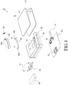
- FIG. 1 is an exploded perspective view illustrating the configuration of a card reader according to an embodiment of the present invention
- FIG. 2 is a perspective view illustrating the coupled state of the card reader according to the embodiment of the present invention.
- the configuration of the card reader 10 will be described with reference to FIGS. 1 and 2 .
- the card reader 10 includes a card reader main body 20, a contact type card identification module 30, a circuit board 40 having a non-contact type card identification module 70 mounted thereon, a card insertion opening 50; and a rotation guide unit 60.
- the card reader main body 20 is configured such that the contact type card identification module 30, the circuit board 40, the card insertion opening 50, and the rotation guide unit 60, which will be described below, may be provided therein.
- the contact type card identification module 30 is provided in the card reader main body 20 to identify a contact type card 11, which will be described below.
- the circuit board 40 has the non-contact type card identification module 70 mounted thereon for identifying a non-contact type card 12, which will be described below, and is provided in the card reader main body 20.
- the card insertion opening 50 into which both the contact type card 11 and the non-contact type card 12 may be inserted, is formed in the card reader main body 20.
- the rotation guide unit 60 is rotatably provided in the card insertion opening. The rotation guide unit 60 passes the contact type card 11 through the card insertion opening 50 according to the rotation thereof such that the contact type card identification module 30 may identify a magnetic stripe (not illustrated) provided on the contact type card 11.
- the rotation guide unit 60 restricts the movement of the non-contact type card 12 according to the contact therewith after the non-contact type card 12 is inserted into the card insertion opening 50 such that the non-contact type card identification module 70 may identify an IC chip 12a provided in the non-contact type card 12.
- the rotation guide unit 60 passes the contact type card 11 through the card insertion opening 50 while rotating at the same time as making contact with the contact type card 11.
- the rotation guide unit 60 restricts the movement of the non-contact type card 12 within the card insertion opening 50 without rotating when it makes contact with the non-contact type card 12 that is inserted into the card insertion opening 50.
- the single card insertion opening 50 is formed in the card reader main body 20 such that both the contact type card 11 and the non-contact type card 12 may be identified and used at the same moment they are inserted into the card insertion opening 50. Accordingly, both the contact type card 11 and the non-contact type card 12 can be used in the single card reader, instead of a contact type card reader and a non-contact type card reader, thereby enhancing the use of the product and reducing the cost required for additionally purchasing a product.
- a cover 90 is provided on the exterior of the card reader main body 20.
- the cover 90 is coupled to the card reader main body 20 to protect the card reader main body 20.
- first and second connection terminals 41 and 42 are mounted on the circuit board 40 to electrically connect the card reader main body 20 and external electronic devices (not illustrated).
- the first connection terminal 41 may include a connection jack
- the second connection terminal 42 may include a USB terminal.
- the first and second connection terminals 41 and 42 are exemplified by the connection jack and the USB terminal, respectively, but they are not limited thereto. Namely, any other configurations that may be electrically connected with the external electronic devices (not illustrated) may be applied as various modified examples of the first and second connection terminals 41 and 42.
- the electronic device includes all information and communication devices and multimedia devices, such as a Portable Multimedia Player (PMP), an MP3 player, a navigation, a game player, a notebook, a netbook, an advertising panel, a TV, a digital broadcasting receiver, a Personal Digital Assistant, and a smart phone, as well as all kinds of mobile communication terminals which operate according to communication protocols corresponding to various communication systems, and application devices thereof.
- PMP Portable Multimedia Player
- MP3 player MP3 player
- a navigation a game player
- a notebook a notebook
- a netbook an advertising panel
- TV TV
- digital broadcasting receiver a digital broadcasting receiver
- a Personal Digital Assistant Personal Digital Assistant
- a battery unit 80 is provided in the card reader main body 20 to supply power to the contact type card identification module 30 and the non-contact type card identification module 70.
- the contact type card identification module 30 is constituted by a magnetic head unit in which a Magnetic Stripe Reader (MSR) is installed to detect data stored in the magnetic stripe (not illustrated) that is provided on the contact type card 11. Namely, at the same moment the contact type card 11 makes contact with the rotation guide unit 60 when passing through the card insertion opening 50, the rotation guide unit 60 rotates to pass the contact type card 11.
- the magnetic head unit detects and reads the data stored in the magnetic stripe of the contact type card 11 at the same moment the magnetic stripe (not illustrated) of the contact type card 11 passes through the magnetic head unit.
- the contact type card 11 may be a magnetic card having a magnetic stripe provided thereon.
- the contact type card 11 is exemplified by the magnetic card in this embodiment, but it is not limited thereto. Namely, any other card configurations from which the magnetic head unit may read data at the same moment they make contact with the magnetic head unit may be applied as various modified examples of the contact type card 11.
- the non-contact type card identification module 70 is constituted by a reader that reads information stored in the IC chip 12a that is provided within the non-contact type card 12. Namely, if the rotation guide unit 60 restricts the movement of the non-contact type card 12 while making contact with it at the same moment the non-contact type card 12 is inserted into the card insertion opening 50, the reader reads the information stored in the IC chip 12a of the non-contact type card 12.
- the non-contact type card 12 may be an IC card having the IC chip 12a therein.
- the non-contact type card 12 is exemplified by the IC card in this embodiment, but it is not limited thereto. Namely, any other card configurations that may not make contact with the reader may be applied as various modified examples of the non-contact type card 12.
- the rotation guide unit 60 includes a rotation hole 61, a rotary part 62, a rotation hinge part 63, and a resilient member 64.
- the rotation hole 61 is formed in the card reader main body 20 in order to rotate the rotary part 62 therein and restrict the rotation of the rotary part 62.
- the rotary part 62 is provided in the rotation hole 61 in order to pass the contact type card 11 through the card insertion opening while rotating at the same time as making contact with the contact type card 11 and to restrict the movement of the non-contact type card 12 within the card insertion opening while making contact with the non-contact type card 12.
- the rotation hinge part 63 is located adjacent to the rotation hole 61 to rotatably support the rotary part 62.
- the resilient member 64 is coupled to the rotary part 62 and provides a resilient force in order to rotate the rotary part 62.
- the resilient member 64 may be constituted by a wire spring, and other types of springs, such as a coil spring and a plate spring, may be employed for the resilient member 64, as well as the wire spring.
- a contact stopper 61a is formed in the rotation hole 61 such that the rotary part 62 makes contact with the contact stopper 61a to restrict the movement of the non-contact type card 12 after the non-contact type card 12 is inserted into the card insertion opening 50.
- the contact stopper 61a restricts the rotation of the rotary part 62 while making contact with one end of the rotary part 62.
- the contact type card 11 makes contact with the rotary part 62 to rotate the rotary part 62 while separating the end of the rotary part 62 from the contact stopper 61a. In this way, the contact type card 11 passes through the card insertion opening 50.
- the rotary part 62 rotates by the resilient member 64 and returns to the original position, in which case the end of the rotary part 62 makes contact with the contact stopper 61a so that the rotation of the rotary part 62 is restricted by the contact stopper 61a.
- the non-contact type card 12 When the non-contact type card 12 is inserted into an inlet at the opposite side of the card insertion opening 50, the non-contact type card 12 makes contact with the rotary part 62 so that the movement of the non-contact type card 12 is restricted by the rotary part 62.
- the non-contact type card 12 inserted into the card insertion opening 50 is identified by the non-contact type card identification module 70 that is provided in the card reader main body 20.
- the rotary part 62 is rotatably coupled to the card reader main body 20 in which the card insertion opening 50 is formed as illustrated in FIGS. 1 and 2 .
- the rotary part 62 is provided so as to be rotatable within the rotation hole 61 that is formed in the card reader main body 20 to receive the rotary part 62 therein.
- the rotary part 62 is rotatably coupled to the rotation hinge part 63 that is located adjacent to the rotation hole 61 to support the rotation of the rotary part 62.
- the rotation hinge part 63 is screw-coupled to the card reader main body 20.
- the rotation hinge part 63 has hinge holes 63a formed on opposite sides thereof, and hinge arms 62a of the rotary part 62 are coupled to the hinge holes 63a.
- the resilient member 64 is mounted on one of the hinge arms 62a of the rotary part 62 in order to apply a resilient force to the rotary part.
- the contact type card identification module 30 and the circuit board 40 on which the non-contact type card identification module 70 is mounted are provided in the card reader main body 20.
- the contact type card identification module 30 and the non-contact type card identification module 70 are arranged side by side in the card reader main body 20.
- the battery unit 80 is provided in the card reader main body 20 to supply power to the non-contact type card identification module 70.
- the cover 90 is mounted on the exterior of the card reader main body 20.
- FIG. 3 is a plan view illustrating a state in which the contact type card 11 is inserted into the card insertion opening 50 of the card reader main body 20 according to the present invention.
- FIG. 4 is an enlarged plan view of portion A of FIG. 3 .
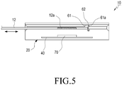
- FIG. 5 is a plan view illustrating a state in which the non-contact type card 12 is inserted into the card insertion opening 50 of the card reader main body 20 according to the present invention.
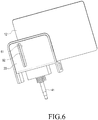
- FIG. 6 is a side view illustrating the state in which the card reader, according to the present invention, is used for the non-contact type card 12.
- FIG. 7 is a perspective view illustrating a state in which the non-contact type card 12 and the rotation guide unit 60 make contact with each other in the card reader according to the embodiment of the present invention.
- the contact type card 11 is inserted into the card insertion opening 50 through one side thereof and passes through the card insertion opening 50. Namely, when the contact type card 11 starts from one side of the card insertion opening 50 and passes through the card insertion opening 50 from the left to the right, the contact type card 11 makes contact with the rotary part 62 of the rotation guide unit 60 at the same moment it is inserted into the card insertion opening 50, and the rotary part 62 rotates at the same moment the contact-type card 11 is brought into contact with the rotary part 62, and passes the contact type card 11 through the card insertion opening 50.
- the contact type card identification module 30 provided in the card reader main body 20 reads data stored in the magnetic stripe (not illustrated) that is provided on the contact type card 11.
- the contact type card identification module 30 imparts the data, which is read from the magnetic stripe, to the external electronic devices (not illustrated) through the first and second connection terminals 41 and 42.
- the rotary part 62 rotates again by the resilient member 64 and returns to the original position. At this time, the end of the rotary part 62 makes contact with the contact stopper 61a formed in the rotation hole 61 so that the rotation of the rotary part 62 is restricted.
- the non-contact type card 12 is inserted into the card insertion opening 50 through the opposite side thereof. Namely, when the non-contact type card 12 is inserted into the card insertion opening 50 from the right to the left, the non-contact type card 12 makes contact with the rotary part 62 and stops.
- the non-contact type card 12 when the non-contact type card 12 starts from the opposite side of the card insertion opening 50 and is inserted thereinto from the right to the left, the non-contact type card 12 does not completely pass through the card insertion opening 50, and makes contact with the rotary part 62 in a position that exceeds half of the card insertion opening 50 so that the movement of the non-contact type card 12 is restricted.
- the rotary part 62 does not rotate because the rotary part 62 makes contact with the contact stopper 61a.
- the non-contact type card 12 corresponds to the non-contact type card identification module 70 provided in the card reader main body 20 and is close to the non-contact type card identification module 70.
- the non-contact type card identification module 70 reads and identifies the information of the IC chip 12a (not illustrated) that is provided in the non-contact type card 12.
- an RF module (not illustrated) and an antenna (not illustrated) that are provided in the non-contact type card identification module 70 receive the signal of the non-contact type card 12, and the signal is imparted to a signal processing unit (not illustrated) of the non-contact type card identification module 70.
- the signal processing unit (not illustrated) transmits the signal to the external electronic devices (not illustrated) through the first and second connection terminals 41 and 42.
- an existing contact type card (not illustrated) or non-contact type card (not illustrated)
- the user has to have separate card readers (not illustrated) so that it costs a lot to purchase the products.
- an existing card reader that is usable for both a contact type card and a non-contact type card, which has separate card insertion openings for them, causes an inconvenience to a user because the user has to insert a contact type card into the card insertion opening dedicated to a contact type card in order to use it, and has to insert a non-contact type card into the separate card insertion opening dedicated to a non-contact type card in order to use it.
- the card reader 10 (illustrated in FIG. 1 ) of the present invention is configured such that both the contact type card 11 (illustrated in FIG. 3 ) and the non-contact type card 12 (illustrated in FIG. 5 ) are used through the single card insertion opening 50 (illustrated in FIG. 1 ). Therefore, it is possible to enhance user convenience and to reduce the cost required to purchase a product because there is no need to additionally purchase an existing card reader according to use.
Landscapes
- Engineering & Computer Science (AREA)
- Physics & Mathematics (AREA)
- General Physics & Mathematics (AREA)
- Theoretical Computer Science (AREA)
- Artificial Intelligence (AREA)
- Computer Vision & Pattern Recognition (AREA)
- Coupling Device And Connection With Printed Circuit (AREA)
- Credit Cards Or The Like (AREA)
- Conveying Record Carriers (AREA)
Claims (9)
- Kartenleser (10), umfassend:einen Kartenleserhauptkörper (20);eine Karteneinschuböffnung (50), die im Kartenleserhauptkörper (20) geformt ist und in die eine Karte vom Kontaktyp und eine Karte vom kontaktlosen Typ eingeschoben werden können;dadurch gekennzeichnet, dass eine Rotationsführungseinheit (60) in der Karteneinschuböffnung (50) bereitgestellt ist;wobei die Rotationsführungseinheit (60) angeordnet ist, um die Karte vom Kontakttyp entsprechend der Rotation der Rotationsführungseinheit (60) durch die Karteneinschuböffnung (50) zu leiten;und wobei die Rotationsführungseinheit (60) angeordnet ist, um die Bewegung der Karte vom kontaktlosen Typ entsprechend dem Kontakt der Rotationsführungseinheit (60) mit der Karte vom kontaktlosen Typ, nachdem die Karte vom kontaktlosen Typ in die Karteneinschuböffnung (50) eingeschoben wurde, zu beschränken.
- Kartenleser (10) nach Anspruch 1, wobei ein Identifikationsmodul für Karten vom Kontakttyp (30) und ein Identifikationsmodul für Karten vom kontaktlosen Typ (70) in der Karteneinschuböffnung (50) bereitgestellt sind, um die Karte vom Kontakttyp bzw. die Karte vom kontaktlosen Typ zu identifizieren.
- Kartenleser (10) nach Anspruch 1, ferner umfassend:ein Identifikationsmodul für Karten vom Kontakttyp (30), das im Kartenleserhauptkörper (20) bereitgestellt ist;und eine Leiterplatte (40), die im Kartenleserhauptkörper (20) bereitgestellt ist, wobei die Leiterplatte (40) ein Identifikationsmodul für Karten vom kontaktlosen Typ (70) darauf montiert hat;wobei die Rotationsführungseinheit (60) rotierbar in der Karteneinschuböffnung (50) bereitgestellt ist;wobei die Rotationsführungseinheit (60) angeordnet ist, um die Karte vom Kontakttyp entsprechend der Rotation der Rotationsführungseinheit (60) so durch die Karteneinschuböffnung (50) zu leiten, dass das Identifikationsmodul für Karten von Kontakttyp (30) die Karte vom Kontakttyp identifiziert;und wobei die Rotationsführungseinheit (60) angeordnet ist, um die Bewegung der Karte vom kontaktlosen Typ entsprechend dem Kontakt der Rotationsführungseinheit (60) mit der Karte vom kontaktlosen Typ, nachdem die Karte vom kontaktlosen Typ in die Karteneinschuböffnung (50) eingeschoben wurde, so zu beschränken, dass das Identifikationsmodul für Karten vom kontaktlosen Typ (70) die Karte vom kontaktlosen Typ identifiziert.
- Kartenleser (10) nach Anspruch 3, ferner umfassend:einen ersten und zweiten Anschlusskontakt (41, 42), die auf der Leiterplatte (40) bereitgestellt sind, um den Kartenleserhauptkörper (20) und externe elektronische Geräte elektrisch zu verbinden;wobei der erste Anschlusskontakt (41) mit einer Anschlussbuchse konfiguriert ist, und der zweite Anschlusskontakt (42) mit einem USB-Anschluss konfiguriert ist.
- Kartenleser (10) nach Anspruch 3, ferner umfassend:eine Batterieeinheit (80), die im Kartenleserhauptkörper (20) bereitgestellt ist, um dem Identifikationsmodul für Karten vom Kontakttyp (30) und dem Identifikationsmodul für Karten vom kontaktlosen Typ (70) Energie zuzuführen.
- Kartenleser (10) nach Anspruch 3, wobei die Karte vom Kontakttyp eine magnetische Karte mit einem darauf montierten Magnetstreifen ist und die Karte vom kontaktlosen Typ eine IC-Karte mit einem IC-Chip darin ist.
- Kartenleser (10) nach Anspruch 3, wobei die Rotationsführungseinheit (60) umfasst:ein Rotationsloch (61), das in der Karteneinschuböffnung (50) geformt ist;ein im Rotationsloch (61) bereitgestelltes rotierendes Teil (62), wobei das rotierende Teil (62) den Einschub der Karte vom Kontakttyp in die Karteneinschuböffnung (50) führt, indem es während des Kontakts zur Karte vom Kontakttyp rotiert, und die Bewegung der Karte vom kontaktlosen Typ in der Karteneinschuböffnung (50) einschränkt, indem es Kontakt zur Karte vom kontaktlosen Typ herstellt;ein Rotationsscharnierteil (63), das angrenzend an das Rotationsloch bereitgestellt ist, um das rotierende Teil (62) zu stützen;und ein elastisches Element (64), das mit dem rotierenden Teil (62) gekoppelt ist, um eine elastische Kraft bereitzustellen, um das rotierende Teil (62) zu rotieren.
- Kartenleser (10) nach Anspruch 7, wobei die Rotationsführungseinheit (60) ferner einen Kontaktstopper (61a) umfasst, der im Rotationsloch (61) bereitgestellt ist, um die Rotation des rotierenden Teils (62) einzuschränken, indem er Kontakt zum rotierenden Teil (62) herstellt.
- Kartenleser (10) nach Anspruch 3, ferner umfassend: eine Abdeckung (90), die am Äußeren des Kartenleserhauptkörpers (20) bereitgestellt ist, wobei die Abdeckung (90) mit dem Kartenleserhauptkörper (20) gekoppelt ist, um diesen zu schützen.
Applications Claiming Priority (2)
| Application Number | Priority Date | Filing Date | Title |
|---|---|---|---|
| KR20130147045A KR101510317B1 (ko) | 2013-11-29 | 2013-11-29 | 카드 리더기 |
| PCT/KR2014/010067 WO2015080384A1 (ko) | 2013-11-29 | 2014-10-24 | 카드 리더기 |
Publications (3)
| Publication Number | Publication Date |
|---|---|
| EP3076338A1 EP3076338A1 (de) | 2016-10-05 |
| EP3076338A4 EP3076338A4 (de) | 2017-07-26 |
| EP3076338B1 true EP3076338B1 (de) | 2019-01-30 |
Family
ID=53034536
Family Applications (1)
| Application Number | Title | Priority Date | Filing Date |
|---|---|---|---|
| EP14866465.9A Active EP3076338B1 (de) | 2013-11-29 | 2014-10-24 | Kartenleser |
Country Status (6)
| Country | Link |
|---|---|
| US (1) | US9760741B2 (de) |
| EP (1) | EP3076338B1 (de) |
| JP (1) | JP6291054B2 (de) |
| KR (1) | KR101510317B1 (de) |
| CN (1) | CN106133757B (de) |
| WO (1) | WO2015080384A1 (de) |
Families Citing this family (9)
| Publication number | Priority date | Publication date | Assignee | Title |
|---|---|---|---|---|
| KR101743112B1 (ko) * | 2016-04-18 | 2017-06-02 | 한국정보통신주식회사 | 멀티 카드 리더 모듈 및 이를 이용한 멀티 카드 리더 장치 |
| KR101743120B1 (ko) * | 2016-04-18 | 2017-06-15 | 한국정보통신주식회사 | 멀티 카드 리더 장치 및 그 동작 방법 |
| KR101743116B1 (ko) * | 2016-04-18 | 2017-06-15 | 한국정보통신주식회사 | 멀티 카드 리더 모듈 및 이를 이용한 멀티 카드 리더 장치 |
| KR200487753Y1 (ko) * | 2016-10-28 | 2018-10-30 | 한국정보통신주식회사 | 탈부착 장치를 포함하는 카드 리더기 |
| KR200487752Y1 (ko) * | 2016-10-28 | 2018-10-30 | 한국정보통신주식회사 | 탈부착 장치를 포함하는 카드 리더기 |
| US10198601B2 (en) * | 2017-05-30 | 2019-02-05 | Verifone, Inc. | Card reader with adaptive magnetic head assembly |
| KR102048964B1 (ko) * | 2018-01-23 | 2019-11-26 | (주)엠씨페이 | 다중 카드 결제 장치 및 결제 방법 |
| KR102233003B1 (ko) | 2019-03-12 | 2021-03-26 | 한양대학교 산학협력단 | 슬롯리스 전동기의 코일 조립체, 하우징 및 이를 포함하는 슬롯리스 전동기 |
| KR102048965B1 (ko) * | 2019-09-10 | 2019-11-26 | (주)엠씨페이 | 다중 카드 결제 장치 및 결제 방법 |
Family Cites Families (11)
| Publication number | Priority date | Publication date | Assignee | Title |
|---|---|---|---|---|
| IT1237283B (it) * | 1989-11-22 | 1993-05-27 | Urmet Spa | Dispositivo lettore polivalente di schede di abilitazione di apparecchi telefonici per uso pubblico |
| GB9422803D0 (en) * | 1994-11-11 | 1995-01-04 | At & T Global Inf Solution | A card reader |
| JP3153749B2 (ja) * | 1995-12-13 | 2001-04-09 | 株式会社三協精機製作所 | Icカードリーダ |
| JP3360002B2 (ja) * | 1996-03-14 | 2002-12-24 | 沖電気工業株式会社 | 接触式・非接触式兼用icカード及び接触式・非接触式兼用icカードリーダライタ |
| FR2783069B1 (fr) * | 1998-09-04 | 2003-01-24 | Inside Technologies | Lecteur de carte a puce |
| JP3701534B2 (ja) * | 2000-02-09 | 2005-09-28 | 株式会社三協精機製作所 | カードリーダ |
| JP4323329B2 (ja) * | 2004-01-06 | 2009-09-02 | 日本電産サンキョー株式会社 | カードリーダ |
| BR112012008829A2 (pt) * | 2009-10-13 | 2019-09-24 | Square Inc | sistemas e métodos para geração dinâmica de recibo com informações de ambiente. |
| KR101052496B1 (ko) * | 2009-11-06 | 2011-07-29 | 대성엘앤에이 주식회사 | 이동통신 단말기용 복합 리더기 |
| KR101143856B1 (ko) * | 2011-07-12 | 2012-05-04 | 한국정보통신주식회사 | 카드 리더, 모바일 단말기 및 그 결제 방법 |
| KR200468168Y1 (ko) * | 2012-07-30 | 2013-08-07 | 한국정보통신주식회사 | 카드 리더기 |
-
2013
- 2013-11-29 KR KR20130147045A patent/KR101510317B1/ko active Active
-
2014
- 2014-10-24 WO PCT/KR2014/010067 patent/WO2015080384A1/ko not_active Ceased
- 2014-10-24 CN CN201480065248.4A patent/CN106133757B/zh active Active
- 2014-10-24 EP EP14866465.9A patent/EP3076338B1/de active Active
- 2014-10-24 JP JP2016535164A patent/JP6291054B2/ja active Active
-
2016
- 2016-05-31 US US15/169,372 patent/US9760741B2/en active Active
Non-Patent Citations (1)
| Title |
|---|
| None * |
Also Published As
| Publication number | Publication date |
|---|---|
| JP6291054B2 (ja) | 2018-03-14 |
| CN106133757A (zh) | 2016-11-16 |
| EP3076338A4 (de) | 2017-07-26 |
| WO2015080384A1 (ko) | 2015-06-04 |
| CN106133757B (zh) | 2019-05-28 |
| KR101510317B1 (ko) | 2015-04-14 |
| US20160275316A1 (en) | 2016-09-22 |
| US9760741B2 (en) | 2017-09-12 |
| JP2017503247A (ja) | 2017-01-26 |
| EP3076338A1 (de) | 2016-10-05 |
Similar Documents
| Publication | Publication Date | Title |
|---|---|---|
| EP3076338B1 (de) | Kartenleser | |
| US8670242B2 (en) | Data storage devices | |
| US8604995B2 (en) | Shielding of portable consumer device | |
| US8455779B2 (en) | Chip card device | |
| US20110198395A1 (en) | Handheld mobile credit card reader | |
| KR20080038516A (ko) | 접촉 및 비접촉식 스마트카드용 단말기와 그 단말기 회로 | |
| KR20080039330A (ko) | 접촉 및 비접촉식 스마트카드 단말기용 표시입력장치 및이에 적용되는 전자회로 | |
| CA2607578C (en) | Variable thickness data card body | |
| CN203224904U (zh) | 一种移动存储器、智能卡及其支付终端的集成装置 | |
| KR100923454B1 (ko) | 접이식 카드가이드를 가진 스마트카드 리더기 | |
| US20080277483A1 (en) | Contactless IC card system with partible antenna | |
| US8485443B2 (en) | Apparatus and method for sensing an integrated circuit card | |
| KR100998352B1 (ko) | 회전식 카드가이드를 가진 스마트카드 리더기 | |
| JP2006227678A (ja) | 2ウェイicカード用リーダライタ | |
| CN205354045U (zh) | 一种读卡设备 | |
| KR100809028B1 (ko) | 교통카드용 알에프 모듈 | |
| KR101141809B1 (ko) | Rfid 리더를 가진 이동 단말기용 유심카드장치 | |
| JP2004348363A (ja) | Icモジュール、icモジュール板、及び通信システム | |
| KR200433171Y1 (ko) | 규격화된 다양한 유에스비 장치를 삽입할 수 있는 형태의접촉/비접촉식 스마트칩 및 알에프 안테나가 구비된유에스비 허브 장치 | |
| CN202995916U (zh) | Pos终端机内建无线射频感应装置结构 | |
| TWI483194B (zh) | 可獨立顯示之智慧卡 | |
| KR20060000110U (ko) | 다수의 유에스비장치가 탈착 가능한 형태의 접촉/비접촉식스마트칩 및 알에프안테나가 구비된 유에스비허브장치 | |
| CN202771557U (zh) | 移动支付终端 | |
| KR20200131087A (ko) | 휴대용 카드 리더기 | |
| KR20180093309A (ko) | Rf카드 활성화 장치 |
Legal Events
| Date | Code | Title | Description |
|---|---|---|---|
| PUAI | Public reference made under article 153(3) epc to a published international application that has entered the european phase |
Free format text: ORIGINAL CODE: 0009012 |
|
| 17P | Request for examination filed |
Effective date: 20160603 |
|
| AK | Designated contracting states |
Kind code of ref document: A1 Designated state(s): AL AT BE BG CH CY CZ DE DK EE ES FI FR GB GR HR HU IE IS IT LI LT LU LV MC MK MT NL NO PL PT RO RS SE SI SK SM TR |
|
| AX | Request for extension of the european patent |
Extension state: BA ME |
|
| DAX | Request for extension of the european patent (deleted) | ||
| REG | Reference to a national code |
Ref country code: DE Ref legal event code: R079 Ref document number: 602014040584 Country of ref document: DE Free format text: PREVIOUS MAIN CLASS: G06K0017000000 Ipc: G06K0007000000 |
|
| A4 | Supplementary search report drawn up and despatched |
Effective date: 20170626 |
|
| RIC1 | Information provided on ipc code assigned before grant |
Ipc: G06K 7/00 20060101AFI20170620BHEP Ipc: G06K 13/08 20060101ALI20170620BHEP |
|
| GRAP | Despatch of communication of intention to grant a patent |
Free format text: ORIGINAL CODE: EPIDOSNIGR1 |
|
| STAA | Information on the status of an ep patent application or granted ep patent |
Free format text: STATUS: GRANT OF PATENT IS INTENDED |
|
| INTG | Intention to grant announced |
Effective date: 20180821 |
|
| GRAS | Grant fee paid |
Free format text: ORIGINAL CODE: EPIDOSNIGR3 |
|
| GRAF | Information related to payment of grant fee modified |
Free format text: ORIGINAL CODE: EPIDOSCIGR3 |
|
| GRAA | (expected) grant |
Free format text: ORIGINAL CODE: 0009210 |
|
| STAA | Information on the status of an ep patent application or granted ep patent |
Free format text: STATUS: THE PATENT HAS BEEN GRANTED |
|
| AK | Designated contracting states |
Kind code of ref document: B1 Designated state(s): AL AT BE BG CH CY CZ DE DK EE ES FI FR GB GR HR HU IE IS IT LI LT LU LV MC MK MT NL NO PL PT RO RS SE SI SK SM TR |
|
| REG | Reference to a national code |
Ref country code: GB Ref legal event code: FG4D |
|
| REG | Reference to a national code |
Ref country code: CH Ref legal event code: EP |
|
| REG | Reference to a national code |
Ref country code: AT Ref legal event code: REF Ref document number: 1093844 Country of ref document: AT Kind code of ref document: T Effective date: 20190215 |
|
| REG | Reference to a national code |
Ref country code: IE Ref legal event code: FG4D |
|
| REG | Reference to a national code |
Ref country code: DE Ref legal event code: R096 Ref document number: 602014040584 Country of ref document: DE |
|
| REG | Reference to a national code |
Ref country code: LT Ref legal event code: MG4D |
|
| REG | Reference to a national code |
Ref country code: NL Ref legal event code: MP Effective date: 20190130 |
|
| PG25 | Lapsed in a contracting state [announced via postgrant information from national office to epo] |
Ref country code: PL Free format text: LAPSE BECAUSE OF FAILURE TO SUBMIT A TRANSLATION OF THE DESCRIPTION OR TO PAY THE FEE WITHIN THE PRESCRIBED TIME-LIMIT Effective date: 20190130 Ref country code: NO Free format text: LAPSE BECAUSE OF FAILURE TO SUBMIT A TRANSLATION OF THE DESCRIPTION OR TO PAY THE FEE WITHIN THE PRESCRIBED TIME-LIMIT Effective date: 20190430 Ref country code: PT Free format text: LAPSE BECAUSE OF FAILURE TO SUBMIT A TRANSLATION OF THE DESCRIPTION OR TO PAY THE FEE WITHIN THE PRESCRIBED TIME-LIMIT Effective date: 20190530 Ref country code: SE Free format text: LAPSE BECAUSE OF FAILURE TO SUBMIT A TRANSLATION OF THE DESCRIPTION OR TO PAY THE FEE WITHIN THE PRESCRIBED TIME-LIMIT Effective date: 20190130 Ref country code: FI Free format text: LAPSE BECAUSE OF FAILURE TO SUBMIT A TRANSLATION OF THE DESCRIPTION OR TO PAY THE FEE WITHIN THE PRESCRIBED TIME-LIMIT Effective date: 20190130 Ref country code: NL Free format text: LAPSE BECAUSE OF FAILURE TO SUBMIT A TRANSLATION OF THE DESCRIPTION OR TO PAY THE FEE WITHIN THE PRESCRIBED TIME-LIMIT Effective date: 20190130 Ref country code: ES Free format text: LAPSE BECAUSE OF FAILURE TO SUBMIT A TRANSLATION OF THE DESCRIPTION OR TO PAY THE FEE WITHIN THE PRESCRIBED TIME-LIMIT Effective date: 20190130 Ref country code: LT Free format text: LAPSE BECAUSE OF FAILURE TO SUBMIT A TRANSLATION OF THE DESCRIPTION OR TO PAY THE FEE WITHIN THE PRESCRIBED TIME-LIMIT Effective date: 20190130 |
|
| REG | Reference to a national code |
Ref country code: AT Ref legal event code: MK05 Ref document number: 1093844 Country of ref document: AT Kind code of ref document: T Effective date: 20190130 |
|
| PG25 | Lapsed in a contracting state [announced via postgrant information from national office to epo] |
Ref country code: GR Free format text: LAPSE BECAUSE OF FAILURE TO SUBMIT A TRANSLATION OF THE DESCRIPTION OR TO PAY THE FEE WITHIN THE PRESCRIBED TIME-LIMIT Effective date: 20190501 Ref country code: HR Free format text: LAPSE BECAUSE OF FAILURE TO SUBMIT A TRANSLATION OF THE DESCRIPTION OR TO PAY THE FEE WITHIN THE PRESCRIBED TIME-LIMIT Effective date: 20190130 Ref country code: LV Free format text: LAPSE BECAUSE OF FAILURE TO SUBMIT A TRANSLATION OF THE DESCRIPTION OR TO PAY THE FEE WITHIN THE PRESCRIBED TIME-LIMIT Effective date: 20190130 Ref country code: IS Free format text: LAPSE BECAUSE OF FAILURE TO SUBMIT A TRANSLATION OF THE DESCRIPTION OR TO PAY THE FEE WITHIN THE PRESCRIBED TIME-LIMIT Effective date: 20190530 Ref country code: RS Free format text: LAPSE BECAUSE OF FAILURE TO SUBMIT A TRANSLATION OF THE DESCRIPTION OR TO PAY THE FEE WITHIN THE PRESCRIBED TIME-LIMIT Effective date: 20190130 Ref country code: BG Free format text: LAPSE BECAUSE OF FAILURE TO SUBMIT A TRANSLATION OF THE DESCRIPTION OR TO PAY THE FEE WITHIN THE PRESCRIBED TIME-LIMIT Effective date: 20190430 |
|
| PG25 | Lapsed in a contracting state [announced via postgrant information from national office to epo] |
Ref country code: AL Free format text: LAPSE BECAUSE OF FAILURE TO SUBMIT A TRANSLATION OF THE DESCRIPTION OR TO PAY THE FEE WITHIN THE PRESCRIBED TIME-LIMIT Effective date: 20190130 Ref country code: CZ Free format text: LAPSE BECAUSE OF FAILURE TO SUBMIT A TRANSLATION OF THE DESCRIPTION OR TO PAY THE FEE WITHIN THE PRESCRIBED TIME-LIMIT Effective date: 20190130 Ref country code: DK Free format text: LAPSE BECAUSE OF FAILURE TO SUBMIT A TRANSLATION OF THE DESCRIPTION OR TO PAY THE FEE WITHIN THE PRESCRIBED TIME-LIMIT Effective date: 20190130 Ref country code: RO Free format text: LAPSE BECAUSE OF FAILURE TO SUBMIT A TRANSLATION OF THE DESCRIPTION OR TO PAY THE FEE WITHIN THE PRESCRIBED TIME-LIMIT Effective date: 20190130 Ref country code: IT Free format text: LAPSE BECAUSE OF FAILURE TO SUBMIT A TRANSLATION OF THE DESCRIPTION OR TO PAY THE FEE WITHIN THE PRESCRIBED TIME-LIMIT Effective date: 20190130 Ref country code: EE Free format text: LAPSE BECAUSE OF FAILURE TO SUBMIT A TRANSLATION OF THE DESCRIPTION OR TO PAY THE FEE WITHIN THE PRESCRIBED TIME-LIMIT Effective date: 20190130 Ref country code: SK Free format text: LAPSE BECAUSE OF FAILURE TO SUBMIT A TRANSLATION OF THE DESCRIPTION OR TO PAY THE FEE WITHIN THE PRESCRIBED TIME-LIMIT Effective date: 20190130 |
|
| REG | Reference to a national code |
Ref country code: DE Ref legal event code: R097 Ref document number: 602014040584 Country of ref document: DE |
|
| PG25 | Lapsed in a contracting state [announced via postgrant information from national office to epo] |
Ref country code: SM Free format text: LAPSE BECAUSE OF FAILURE TO SUBMIT A TRANSLATION OF THE DESCRIPTION OR TO PAY THE FEE WITHIN THE PRESCRIBED TIME-LIMIT Effective date: 20190130 |
|
| PLBE | No opposition filed within time limit |
Free format text: ORIGINAL CODE: 0009261 |
|
| STAA | Information on the status of an ep patent application or granted ep patent |
Free format text: STATUS: NO OPPOSITION FILED WITHIN TIME LIMIT |
|
| PG25 | Lapsed in a contracting state [announced via postgrant information from national office to epo] |
Ref country code: AT Free format text: LAPSE BECAUSE OF FAILURE TO SUBMIT A TRANSLATION OF THE DESCRIPTION OR TO PAY THE FEE WITHIN THE PRESCRIBED TIME-LIMIT Effective date: 20190130 |
|
| 26N | No opposition filed |
Effective date: 20191031 |
|
| PG25 | Lapsed in a contracting state [announced via postgrant information from national office to epo] |
Ref country code: SI Free format text: LAPSE BECAUSE OF FAILURE TO SUBMIT A TRANSLATION OF THE DESCRIPTION OR TO PAY THE FEE WITHIN THE PRESCRIBED TIME-LIMIT Effective date: 20190130 |
|
| PG25 | Lapsed in a contracting state [announced via postgrant information from national office to epo] |
Ref country code: TR Free format text: LAPSE BECAUSE OF FAILURE TO SUBMIT A TRANSLATION OF THE DESCRIPTION OR TO PAY THE FEE WITHIN THE PRESCRIBED TIME-LIMIT Effective date: 20190130 |
|
| PG25 | Lapsed in a contracting state [announced via postgrant information from national office to epo] |
Ref country code: MC Free format text: LAPSE BECAUSE OF FAILURE TO SUBMIT A TRANSLATION OF THE DESCRIPTION OR TO PAY THE FEE WITHIN THE PRESCRIBED TIME-LIMIT Effective date: 20190130 |
|
| REG | Reference to a national code |
Ref country code: CH Ref legal event code: PL |
|
| PG25 | Lapsed in a contracting state [announced via postgrant information from national office to epo] |
Ref country code: LU Free format text: LAPSE BECAUSE OF NON-PAYMENT OF DUE FEES Effective date: 20191024 Ref country code: CH Free format text: LAPSE BECAUSE OF NON-PAYMENT OF DUE FEES Effective date: 20191031 Ref country code: LI Free format text: LAPSE BECAUSE OF NON-PAYMENT OF DUE FEES Effective date: 20191031 |
|
| REG | Reference to a national code |
Ref country code: BE Ref legal event code: MM Effective date: 20191031 |
|
| PG25 | Lapsed in a contracting state [announced via postgrant information from national office to epo] |
Ref country code: BE Free format text: LAPSE BECAUSE OF NON-PAYMENT OF DUE FEES Effective date: 20191031 |
|
| PG25 | Lapsed in a contracting state [announced via postgrant information from national office to epo] |
Ref country code: IE Free format text: LAPSE BECAUSE OF NON-PAYMENT OF DUE FEES Effective date: 20191024 |
|
| PG25 | Lapsed in a contracting state [announced via postgrant information from national office to epo] |
Ref country code: CY Free format text: LAPSE BECAUSE OF FAILURE TO SUBMIT A TRANSLATION OF THE DESCRIPTION OR TO PAY THE FEE WITHIN THE PRESCRIBED TIME-LIMIT Effective date: 20190130 |
|
| PG25 | Lapsed in a contracting state [announced via postgrant information from national office to epo] |
Ref country code: MT Free format text: LAPSE BECAUSE OF FAILURE TO SUBMIT A TRANSLATION OF THE DESCRIPTION OR TO PAY THE FEE WITHIN THE PRESCRIBED TIME-LIMIT Effective date: 20190130 Ref country code: HU Free format text: LAPSE BECAUSE OF FAILURE TO SUBMIT A TRANSLATION OF THE DESCRIPTION OR TO PAY THE FEE WITHIN THE PRESCRIBED TIME-LIMIT; INVALID AB INITIO Effective date: 20141024 |
|
| PG25 | Lapsed in a contracting state [announced via postgrant information from national office to epo] |
Ref country code: MK Free format text: LAPSE BECAUSE OF FAILURE TO SUBMIT A TRANSLATION OF THE DESCRIPTION OR TO PAY THE FEE WITHIN THE PRESCRIBED TIME-LIMIT Effective date: 20190130 |
|
| PGFP | Annual fee paid to national office [announced via postgrant information from national office to epo] |
Ref country code: GB Payment date: 20250919 Year of fee payment: 12 |
|
| PGFP | Annual fee paid to national office [announced via postgrant information from national office to epo] |
Ref country code: DE Payment date: 20251023 Year of fee payment: 12 |
|
| PGFP | Annual fee paid to national office [announced via postgrant information from national office to epo] |
Ref country code: FR Payment date: 20251030 Year of fee payment: 12 |