EP3076418A1 - Système de signalisation lumineuse pour dispositifs de contrôle et de commande électriques - Google Patents
Système de signalisation lumineuse pour dispositifs de contrôle et de commande électriques Download PDFInfo
- Publication number
- EP3076418A1 EP3076418A1 EP15382167.3A EP15382167A EP3076418A1 EP 3076418 A1 EP3076418 A1 EP 3076418A1 EP 15382167 A EP15382167 A EP 15382167A EP 3076418 A1 EP3076418 A1 EP 3076418A1
- Authority
- EP
- European Patent Office
- Prior art keywords
- light
- control
- signalling
- lighting
- electric control
- Prior art date
- Legal status (The legal status is an assumption and is not a legal conclusion. Google has not performed a legal analysis and makes no representation as to the accuracy of the status listed.)
- Granted
Links
Images


Classifications
-
- H—ELECTRICITY
- H01—ELECTRIC ELEMENTS
- H01H—ELECTRIC SWITCHES; RELAYS; SELECTORS; EMERGENCY PROTECTIVE DEVICES
- H01H19/00—Switches operated by an operating part which is rotatable about a longitudinal axis thereof and which is acted upon directly by a solid body external to the switch, e.g. by a hand
- H01H19/02—Details
- H01H19/025—Light-emitting indicators
-
- H—ELECTRICITY
- H01—ELECTRIC ELEMENTS
- H01H—ELECTRIC SWITCHES; RELAYS; SELECTORS; EMERGENCY PROTECTIVE DEVICES
- H01H9/00—Details of switching devices, not covered by groups H01H1/00 - H01H7/00
- H01H9/16—Indicators for switching condition, e.g. "on" or "off"
- H01H9/167—Circuits for remote indication
-
- H—ELECTRICITY
- H01—ELECTRIC ELEMENTS
- H01H—ELECTRIC SWITCHES; RELAYS; SELECTORS; EMERGENCY PROTECTIVE DEVICES
- H01H9/00—Details of switching devices, not covered by groups H01H1/00 - H01H7/00
- H01H9/18—Distinguishing marks on switches, e.g. for indicating switch location in the dark; Adaptation of switches to receive distinguishing marks
- H01H9/181—Distinguishing marks on switches, e.g. for indicating switch location in the dark; Adaptation of switches to receive distinguishing marks using a programmable display, e.g. LED or LCD
Definitions
- This invention consists in a light-signalling system built into electric control and command devices to show the position and/or status of the installation, machine or circuit it controls.
- control switches govern other main power switches, using lights to identify the status of the circuits by means of lighting systems.
- This invention aims to provide a light-signalling system, in combination with a switch, corresponding to a control with fitted lights, which by using signals that are external or internal to the command-switch assembly, make changes in the lighting mode according to programmed parameters, so that it is possible to signal either the position of the control, status of the installation, machine or circuit, or both options at once and in a simple and economic manner.
- This invention is materialised in a light-signalling system that can be fitted to electrical control devices, mainly to switching devices, with an illuminated control device that carries out a change in lighting according to the signals captured internally or received from outside, according to the configuration of the module that governs the parameters for the changes of this type of lighting.
- these signals can be internal, such as the detection of the functional position of said control, and/or external signals such as the impulses generated by elements that indicate the status of elements in the installation, machine or circuit it is connected to.
- a certain lighting mode is established, either no lighting, lit in a certain colour, flashing or even acoustic devices can be fitted to add sound to the signals received.
- the light-signalling module is fitted to the control device with means to disconnect it in case of maintenance.
- the light-signalling module has a system for changing the lighting mode, which receives at least one signal from components external or internal to the light-signalling and switching module, connected to said lighting changing system, which, according to the programming of its electronic circuits, will implement a certain type of lighting.
- This connection can be direct for internal signals or through a module connection terminal strip for external signals.
- Each of the signals in the lighting mode change system is associated to a certain lighting mode, according to the needs of the installation, machine or circuit, the change in lighting mode happens automatically whenever there is a signal. These changes can be switching on or off the lighting, changing the colour of the light, flashing the light or even changing colour while flashing, as well as acoustic signals.
- Configuration of lighting modes governed by the lighting mode change system is carried out according to the user's criteria, and the lighting mode assigned to each of the signals received by the system can be changed according to needs. This configuration is carried out by programming the electronic circuit in the lighting mode change system.
- this signal will preferably correspond to the signal generated by the means to detect the position of the control, therefore, according to its position, these means for detecting position will send a signal that will depend on the position, so that when the lighting mode change system receives the signal, it will change the lighting to the pre-established configuration for this new position.
- one or more external signals are connected to the lighting mode change system, they will connect preferably through an exterior terminal strip, with the elements that act as controllers of the status of the installation, machine or circuit, such as PLCs, thermocouples or any other element generating a sustained electrical impulse, so as to indicate the status, excess temperature, status of a motor connected to a circuit, etc., several of them can be connected to the lighting mode change system, each of them having preferably an input on the terminal strip, and for each signal received from each of them, the lighting mode change system has an assigned lighting mode, by programming the electronic circuit.
- the external terminal strip will have as many connections as signals are to be received in the lighting mode change system.
- the lighting mode change system can in turn have at least one internal signal connection corresponding to the means for detecting the position of the control, and at least one connection to components external to the control device and the lighting module.
- These lighting modes can be accompanied by an acoustic effect produced by means built into the lighting module, as a complement to the illuminated signals.
- the configuration of the lighting mode change system can be reprogrammed to change the association of each of the inputs of the external or internal signals to the assigned lighting mode.
- the light-signalling system comprising a casing that contains means to attach to the switching device, with a control that enables the lighting mode produced by the interior lighting devices to be viewed, governed by at least one system to change the lighting mode that has at least one signal input, which can be either internal and/or external to the switch assembly and the lighting module.
- This module can be made as a modular system, in which the lighting module is designed to fit to different standard switches, although this needs the incorporation of an extension of the control shaft to attach to the movement with the control device shaft.
- the switch control is preferably made of material that lets light through it, normally plastic, to allow the installation of means to generate light inside the module, and which can be transmitted by means of the control, lighting up the control for each of its positions.
- Other solutions are possible, as long as this lighting is provided and the changes in lighting mode can be seen by the user.
- the means for lighting are preferably LEDs located in their specific housing.
- the LEDs are fitted in such a manner to ensure that the failure of one of them will not affect the safety of the installation or the failure of the module itself, falsifying the visual information provided by the device, so there are several series of parallel LEDs, so that in case of a failure, the module will still light up. This considerably increases the life of the device and its safety in comparison to current devices.
- the switch control that the signalling module is incorporated into may incorporate means to carry out physical locking of the position by means of a padlock or similar element, to insure that the control position cannot be altered.
- the operating procedure incorporated into the light signal module for electric control devices is based on its connection in the installation, machine or circuit, so that the system for changing the lighting mode will execute actions on the lights.
- the different functional positions of the control corresponding to the physical positions, are assigned a specific lighting mode and they are the means to detect the position of the control, and/or the impulses of the elements of the circuit that register its status, those that act sending signals about the lighting mode change module.
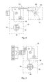
- the light-signalling module (10) is fitted to a switch (11), which executes the operations carried out by the control (12).
- the light-signalling system (10) has means for attachment (15), normally fasteners, allowing it to be detached from the switch (11) for maintenance or replacement. To attach it, the switch shaft must coincide with the control shaft (12) of the light-signalling module (10), as well as with the rest of elements that depend on each other.
- the light-signalling module (10) comprises a casing (20) made of plastic material or the like, covering the elements inside the module (10).
- This control (12) is formed by a component that in this embodiment is triangular in section, although other shapes are possible, where the inner and outer faces of the control (12) are made in such a way that they are translucent, so that light emitted by the series of LEDs (18) that act as means of lighting can be clearly seen and which are in the housing (19).
- the series of LEDs (18) are housed (19) inside the casing (20), in areas where the light can be transmitted to the control (12).
- the LEDs (18) are commonly distributed so that they form different series of several LEDs (18), these series are placed in parallel, providing extended service life to the module (10) and guaranteeing correct operation.
- These series of LEDs (18) are powered and governed by the lighting mode change system (13), which has an electronic circuit (14) that receives the signals, which in this first embodiment (as shown in Figure 3 ) are only internal to the switch (11) and light-signalling assembly (10), such as the signals received by the means (22) for detecting the control position, which correspond to sensors strategically placed in the operating positions of the control (12), which emit a sustained electrical impulse when the f the control is positioned over a strategic position of the detecting sensor, such as for example those carried out by the magnetic sensors.
- the system for changing the lighting mode (13) stems from an aerial connection (21) by means of a terminal strip, that is connected to the circuit (14), and to these connections (21) of the terminal strip the components (24) of the installation that control or enable the user to know the status of the installation, such as PLCs, thermocouples, or any other element generating a sustained electrical impulse are connected, indicating the status, excessive temperature, the state of a motor connected to the circuit, lack of power of any component, etc.
- the circuit (14) is programmed to execute a specific lighting mode in the LEDs (18), which on receiving another signal, will change to this new mode of lighting.
- a sound can be produced from the sound production devices (23). This associates the type of signal, its input, and the programming of changes in lighting mode.
- the lighting mode change system incorporates internal and external signals, the external ones coming from the connection (21) through the terminals strip to which the components (24) of the installation are connected, detectors (22) of control (12) position are also connected to the circuit (14). Its operation, similar to the previous, allows the functions of the previous two embodiments to be integrated into a single one, where it is possible to grant signalling priorities to internal signals or vice versa, associating different lighting modes (colours, absence of lighting, flashing and/or sounds) to each of these signals.
- the electronic circuit (14) can be designed to operate connected to a DC or AC circuit.
- the switch (11) incorporates means for the physical locking (16) of the position of the control (12), by means of padlocks or similar devices.
Landscapes
- Circuit Arrangement For Electric Light Sources In General (AREA)
Priority Applications (3)
| Application Number | Priority Date | Filing Date | Title |
|---|---|---|---|
| PT153821673T PT3076418T (pt) | 2015-04-01 | 2015-04-01 | Sistema de sinalização luminosa para dispositivos de controlo e de comando elétricos |
| EP15382167.3A EP3076418B1 (fr) | 2015-04-01 | 2015-04-01 | Système de signalisation lumineuse pour dispositifs de contrôle et de commande électriques |
| ES15382167.3T ES2644015T3 (es) | 2015-04-01 | 2015-04-01 | Sistema de señalización luminosa para dispositivos eléctricos de control y de mando |
Applications Claiming Priority (1)
| Application Number | Priority Date | Filing Date | Title |
|---|---|---|---|
| EP15382167.3A EP3076418B1 (fr) | 2015-04-01 | 2015-04-01 | Système de signalisation lumineuse pour dispositifs de contrôle et de commande électriques |
Publications (2)
| Publication Number | Publication Date |
|---|---|
| EP3076418A1 true EP3076418A1 (fr) | 2016-10-05 |
| EP3076418B1 EP3076418B1 (fr) | 2017-07-19 |
Family
ID=52998010
Family Applications (1)
| Application Number | Title | Priority Date | Filing Date |
|---|---|---|---|
| EP15382167.3A Active EP3076418B1 (fr) | 2015-04-01 | 2015-04-01 | Système de signalisation lumineuse pour dispositifs de contrôle et de commande électriques |
Country Status (3)
| Country | Link |
|---|---|
| EP (1) | EP3076418B1 (fr) |
| ES (1) | ES2644015T3 (fr) |
| PT (1) | PT3076418T (fr) |
Cited By (1)
| Publication number | Priority date | Publication date | Assignee | Title |
|---|---|---|---|---|
| WO2022017074A1 (fr) * | 2020-07-20 | 2022-01-27 | 华为数字能源技术有限公司 | Structure de surveillance d'état de stockage d'énergie et commutateur rotatif |
Citations (5)
| Publication number | Priority date | Publication date | Assignee | Title |
|---|---|---|---|---|
| US5710544A (en) * | 1994-11-30 | 1998-01-20 | Lg Electronics Inc. | Operation state display apparatus for shuttle switch and displaying method thereof |
| US20050155159A1 (en) * | 2001-08-06 | 2005-07-21 | Peterson Gregory A. | Method for controlling a hyperspin mode in an appliance |
| DE102008035458A1 (de) * | 2008-02-22 | 2009-08-27 | Volkswagen Ag | Bedienvorrichtung für mehrere Funktionen und Verfahren |
| WO2010071922A1 (fr) * | 2008-12-22 | 2010-07-01 | Clipsal Australia Pty Ltd | Interrupteur électrique rotatif verrouillable |
| US20110030609A1 (en) * | 2009-08-04 | 2011-02-10 | Janardhan Kindikeri | Method and apparatus for indicia selection |
-
2015
- 2015-04-01 ES ES15382167.3T patent/ES2644015T3/es active Active
- 2015-04-01 EP EP15382167.3A patent/EP3076418B1/fr active Active
- 2015-04-01 PT PT153821673T patent/PT3076418T/pt unknown
Patent Citations (5)
| Publication number | Priority date | Publication date | Assignee | Title |
|---|---|---|---|---|
| US5710544A (en) * | 1994-11-30 | 1998-01-20 | Lg Electronics Inc. | Operation state display apparatus for shuttle switch and displaying method thereof |
| US20050155159A1 (en) * | 2001-08-06 | 2005-07-21 | Peterson Gregory A. | Method for controlling a hyperspin mode in an appliance |
| DE102008035458A1 (de) * | 2008-02-22 | 2009-08-27 | Volkswagen Ag | Bedienvorrichtung für mehrere Funktionen und Verfahren |
| WO2010071922A1 (fr) * | 2008-12-22 | 2010-07-01 | Clipsal Australia Pty Ltd | Interrupteur électrique rotatif verrouillable |
| US20110030609A1 (en) * | 2009-08-04 | 2011-02-10 | Janardhan Kindikeri | Method and apparatus for indicia selection |
Cited By (1)
| Publication number | Priority date | Publication date | Assignee | Title |
|---|---|---|---|---|
| WO2022017074A1 (fr) * | 2020-07-20 | 2022-01-27 | 华为数字能源技术有限公司 | Structure de surveillance d'état de stockage d'énergie et commutateur rotatif |
Also Published As
| Publication number | Publication date |
|---|---|
| EP3076418B1 (fr) | 2017-07-19 |
| ES2644015T3 (es) | 2017-11-27 |
| PT3076418T (pt) | 2017-10-23 |
Similar Documents
| Publication | Publication Date | Title |
|---|---|---|
| US11694525B2 (en) | Hazard detector with optical status indicator | |
| AU2014253665A1 (en) | Power outlet socket sensor switch | |
| JP6674449B2 (ja) | 緊急オフスイッチ | |
| CN105465703B (zh) | 光学信令装置 | |
| US9889795B1 (en) | System for controlling multiple warning devices mounted on a vehicle to provide warning signals | |
| US20210142638A1 (en) | Hazard detector with optical status indicator | |
| CA2944620A1 (fr) | Dispositif d'affichage equipe d'une interface sans fil et d'une interface avec un systeme de bus d'un systeme de commande en reseau | |
| US11226215B2 (en) | Modular field device kit and method of assembly | |
| AU2013100505A4 (en) | Power Outlet Socket Sensor Switch | |
| EP3076418A1 (fr) | Système de signalisation lumineuse pour dispositifs de contrôle et de commande électriques | |
| CA2132663C (fr) | Clavier de saisie de donnees | |
| CN108089432B (zh) | 紧急控制装置和具有紧急控制装置的安全设备 | |
| EP3462469A1 (fr) | Système d'éclairage d'un appareil de cuisson | |
| US12499744B2 (en) | Operating unit and a method for operating a plant with an operating unit | |
| US20240056333A1 (en) | Extension Module for Function Extension of a Network Assembly | |
| CN111272206A (zh) | 流通式测量站 | |
| EP3043221B1 (fr) | Module de contact et de communication pouvant être actionné manuellement et étant alimenté par un bus | |
| WO2013045189A1 (fr) | Unité de détection, dispositif d'éclairage ayant l'unité de détection et système d'illumination | |
| CN117759915A (zh) | 工业发光装置 | |
| KR101934262B1 (ko) | 무선통신제어방식으로 전자식 스위치와 기기 간의 연동 시스템 | |
| KR101362791B1 (ko) | 배전반 및 이에 이용되는 일체형 조광형 누름 버튼 스위치 | |
| EP4260662B1 (fr) | Système d'éclairage d'urgence intelligent et luminaire | |
| EP4510158A1 (fr) | Dispositif d'arrêt d'urgence d'une machine ou installation industrielle | |
| EP3633639B1 (fr) | Colonne lumineuse pour indiquer un état d'un appareil à surveiller | |
| JP2019121504A (ja) | 設置フリースイッチ装置 |
Legal Events
| Date | Code | Title | Description |
|---|---|---|---|
| PUAI | Public reference made under article 153(3) epc to a published international application that has entered the european phase |
Free format text: ORIGINAL CODE: 0009012 |
|
| 17P | Request for examination filed |
Effective date: 20150416 |
|
| AK | Designated contracting states |
Kind code of ref document: A1 Designated state(s): AL AT BE BG CH CY CZ DE DK EE ES FI FR GB GR HR HU IE IS IT LI LT LU LV MC MK MT NL NO PL PT RO RS SE SI SK SM TR |
|
| AX | Request for extension of the european patent |
Extension state: BA ME |
|
| GRAP | Despatch of communication of intention to grant a patent |
Free format text: ORIGINAL CODE: EPIDOSNIGR1 |
|
| STAA | Information on the status of an ep patent application or granted ep patent |
Free format text: STATUS: GRANT OF PATENT IS INTENDED |
|
| RIC1 | Information provided on ipc code assigned before grant |
Ipc: H01H 9/18 20060101ALI20170203BHEP Ipc: H01H 19/02 20060101ALI20170203BHEP Ipc: H01H 9/16 20060101AFI20170203BHEP |
|
| INTG | Intention to grant announced |
Effective date: 20170222 |
|
| GRAS | Grant fee paid |
Free format text: ORIGINAL CODE: EPIDOSNIGR3 |
|
| GRAA | (expected) grant |
Free format text: ORIGINAL CODE: 0009210 |
|
| STAA | Information on the status of an ep patent application or granted ep patent |
Free format text: STATUS: THE PATENT HAS BEEN GRANTED |
|
| AK | Designated contracting states |
Kind code of ref document: B1 Designated state(s): AL AT BE BG CH CY CZ DE DK EE ES FI FR GB GR HR HU IE IS IT LI LT LU LV MC MK MT NL NO PL PT RO RS SE SI SK SM TR |
|
| REG | Reference to a national code |
Ref country code: GB Ref legal event code: FG4D |
|
| REG | Reference to a national code |
Ref country code: CH Ref legal event code: EP |
|
| REG | Reference to a national code |
Ref country code: IE Ref legal event code: FG4D |
|
| REG | Reference to a national code |
Ref country code: AT Ref legal event code: REF Ref document number: 911114 Country of ref document: AT Kind code of ref document: T Effective date: 20170815 |
|
| REG | Reference to a national code |
Ref country code: DE Ref legal event code: R096 Ref document number: 602015003671 Country of ref document: DE |
|
| REG | Reference to a national code |
Ref country code: PT Ref legal event code: SC4A Ref document number: 3076418 Country of ref document: PT Date of ref document: 20171023 Kind code of ref document: T Free format text: AVAILABILITY OF NATIONAL TRANSLATION Effective date: 20171012 |
|
| REG | Reference to a national code |
Ref country code: NL Ref legal event code: FP |
|
| REG | Reference to a national code |
Ref country code: ES Ref legal event code: FG2A Ref document number: 2644015 Country of ref document: ES Kind code of ref document: T3 Effective date: 20171127 |
|
| REG | Reference to a national code |
Ref country code: LT Ref legal event code: MG4D |
|
| PG25 | Lapsed in a contracting state [announced via postgrant information from national office to epo] |
Ref country code: FI Free format text: LAPSE BECAUSE OF FAILURE TO SUBMIT A TRANSLATION OF THE DESCRIPTION OR TO PAY THE FEE WITHIN THE PRESCRIBED TIME-LIMIT Effective date: 20170719 Ref country code: SE Free format text: LAPSE BECAUSE OF FAILURE TO SUBMIT A TRANSLATION OF THE DESCRIPTION OR TO PAY THE FEE WITHIN THE PRESCRIBED TIME-LIMIT Effective date: 20170719 Ref country code: NO Free format text: LAPSE BECAUSE OF FAILURE TO SUBMIT A TRANSLATION OF THE DESCRIPTION OR TO PAY THE FEE WITHIN THE PRESCRIBED TIME-LIMIT Effective date: 20171019 Ref country code: LT Free format text: LAPSE BECAUSE OF FAILURE TO SUBMIT A TRANSLATION OF THE DESCRIPTION OR TO PAY THE FEE WITHIN THE PRESCRIBED TIME-LIMIT Effective date: 20170719 Ref country code: HR Free format text: LAPSE BECAUSE OF FAILURE TO SUBMIT A TRANSLATION OF THE DESCRIPTION OR TO PAY THE FEE WITHIN THE PRESCRIBED TIME-LIMIT Effective date: 20170719 |
|
| PG25 | Lapsed in a contracting state [announced via postgrant information from national office to epo] |
Ref country code: GR Free format text: LAPSE BECAUSE OF FAILURE TO SUBMIT A TRANSLATION OF THE DESCRIPTION OR TO PAY THE FEE WITHIN THE PRESCRIBED TIME-LIMIT Effective date: 20171020 Ref country code: PL Free format text: LAPSE BECAUSE OF FAILURE TO SUBMIT A TRANSLATION OF THE DESCRIPTION OR TO PAY THE FEE WITHIN THE PRESCRIBED TIME-LIMIT Effective date: 20170719 Ref country code: RS Free format text: LAPSE BECAUSE OF FAILURE TO SUBMIT A TRANSLATION OF THE DESCRIPTION OR TO PAY THE FEE WITHIN THE PRESCRIBED TIME-LIMIT Effective date: 20170719 Ref country code: LV Free format text: LAPSE BECAUSE OF FAILURE TO SUBMIT A TRANSLATION OF THE DESCRIPTION OR TO PAY THE FEE WITHIN THE PRESCRIBED TIME-LIMIT Effective date: 20170719 Ref country code: BG Free format text: LAPSE BECAUSE OF FAILURE TO SUBMIT A TRANSLATION OF THE DESCRIPTION OR TO PAY THE FEE WITHIN THE PRESCRIBED TIME-LIMIT Effective date: 20171019 Ref country code: IS Free format text: LAPSE BECAUSE OF FAILURE TO SUBMIT A TRANSLATION OF THE DESCRIPTION OR TO PAY THE FEE WITHIN THE PRESCRIBED TIME-LIMIT Effective date: 20171119 |
|
| REG | Reference to a national code |
Ref country code: DE Ref legal event code: R097 Ref document number: 602015003671 Country of ref document: DE |
|
| REG | Reference to a national code |
Ref country code: FR Ref legal event code: PLFP Year of fee payment: 4 |
|
| PG25 | Lapsed in a contracting state [announced via postgrant information from national office to epo] |
Ref country code: CZ Free format text: LAPSE BECAUSE OF FAILURE TO SUBMIT A TRANSLATION OF THE DESCRIPTION OR TO PAY THE FEE WITHIN THE PRESCRIBED TIME-LIMIT Effective date: 20170719 Ref country code: RO Free format text: LAPSE BECAUSE OF FAILURE TO SUBMIT A TRANSLATION OF THE DESCRIPTION OR TO PAY THE FEE WITHIN THE PRESCRIBED TIME-LIMIT Effective date: 20170719 Ref country code: DK Free format text: LAPSE BECAUSE OF FAILURE TO SUBMIT A TRANSLATION OF THE DESCRIPTION OR TO PAY THE FEE WITHIN THE PRESCRIBED TIME-LIMIT Effective date: 20170719 |
|
| PLBE | No opposition filed within time limit |
Free format text: ORIGINAL CODE: 0009261 |
|
| STAA | Information on the status of an ep patent application or granted ep patent |
Free format text: STATUS: NO OPPOSITION FILED WITHIN TIME LIMIT |
|
| PG25 | Lapsed in a contracting state [announced via postgrant information from national office to epo] |
Ref country code: SK Free format text: LAPSE BECAUSE OF FAILURE TO SUBMIT A TRANSLATION OF THE DESCRIPTION OR TO PAY THE FEE WITHIN THE PRESCRIBED TIME-LIMIT Effective date: 20170719 Ref country code: SM Free format text: LAPSE BECAUSE OF FAILURE TO SUBMIT A TRANSLATION OF THE DESCRIPTION OR TO PAY THE FEE WITHIN THE PRESCRIBED TIME-LIMIT Effective date: 20170719 Ref country code: EE Free format text: LAPSE BECAUSE OF FAILURE TO SUBMIT A TRANSLATION OF THE DESCRIPTION OR TO PAY THE FEE WITHIN THE PRESCRIBED TIME-LIMIT Effective date: 20170719 |
|
| 26N | No opposition filed |
Effective date: 20180420 |
|
| PG25 | Lapsed in a contracting state [announced via postgrant information from national office to epo] |
Ref country code: SI Free format text: LAPSE BECAUSE OF FAILURE TO SUBMIT A TRANSLATION OF THE DESCRIPTION OR TO PAY THE FEE WITHIN THE PRESCRIBED TIME-LIMIT Effective date: 20170719 |
|
| PG25 | Lapsed in a contracting state [announced via postgrant information from national office to epo] |
Ref country code: MC Free format text: LAPSE BECAUSE OF FAILURE TO SUBMIT A TRANSLATION OF THE DESCRIPTION OR TO PAY THE FEE WITHIN THE PRESCRIBED TIME-LIMIT Effective date: 20170719 |
|
| PG25 | Lapsed in a contracting state [announced via postgrant information from national office to epo] |
Ref country code: LU Free format text: LAPSE BECAUSE OF NON-PAYMENT OF DUE FEES Effective date: 20180401 |
|
| REG | Reference to a national code |
Ref country code: AT Ref legal event code: UEP Ref document number: 911114 Country of ref document: AT Kind code of ref document: T Effective date: 20170719 |
|
| PG25 | Lapsed in a contracting state [announced via postgrant information from national office to epo] |
Ref country code: MT Free format text: LAPSE BECAUSE OF NON-PAYMENT OF DUE FEES Effective date: 20180401 |
|
| PG25 | Lapsed in a contracting state [announced via postgrant information from national office to epo] |
Ref country code: TR Free format text: LAPSE BECAUSE OF FAILURE TO SUBMIT A TRANSLATION OF THE DESCRIPTION OR TO PAY THE FEE WITHIN THE PRESCRIBED TIME-LIMIT Effective date: 20170719 |
|
| PG25 | Lapsed in a contracting state [announced via postgrant information from national office to epo] |
Ref country code: CY Free format text: LAPSE BECAUSE OF FAILURE TO SUBMIT A TRANSLATION OF THE DESCRIPTION OR TO PAY THE FEE WITHIN THE PRESCRIBED TIME-LIMIT Effective date: 20170719 Ref country code: HU Free format text: LAPSE BECAUSE OF FAILURE TO SUBMIT A TRANSLATION OF THE DESCRIPTION OR TO PAY THE FEE WITHIN THE PRESCRIBED TIME-LIMIT; INVALID AB INITIO Effective date: 20150401 Ref country code: MK Free format text: LAPSE BECAUSE OF NON-PAYMENT OF DUE FEES Effective date: 20170719 |
|
| PG25 | Lapsed in a contracting state [announced via postgrant information from national office to epo] |
Ref country code: AL Free format text: LAPSE BECAUSE OF FAILURE TO SUBMIT A TRANSLATION OF THE DESCRIPTION OR TO PAY THE FEE WITHIN THE PRESCRIBED TIME-LIMIT Effective date: 20170719 |
|
| P01 | Opt-out of the competence of the unified patent court (upc) registered |
Effective date: 20230516 |
|
| PGFP | Annual fee paid to national office [announced via postgrant information from national office to epo] |
Ref country code: NL Payment date: 20250424 Year of fee payment: 11 |
|
| PGFP | Annual fee paid to national office [announced via postgrant information from national office to epo] |
Ref country code: DE Payment date: 20250428 Year of fee payment: 11 |
|
| PGFP | Annual fee paid to national office [announced via postgrant information from national office to epo] |
Ref country code: ES Payment date: 20250529 Year of fee payment: 11 |
|
| PGFP | Annual fee paid to national office [announced via postgrant information from national office to epo] |
Ref country code: IT Payment date: 20250422 Year of fee payment: 11 Ref country code: BE Payment date: 20250424 Year of fee payment: 11 |
|
| PGFP | Annual fee paid to national office [announced via postgrant information from national office to epo] |
Ref country code: FR Payment date: 20250424 Year of fee payment: 11 |
|
| PGFP | Annual fee paid to national office [announced via postgrant information from national office to epo] |
Ref country code: CH Payment date: 20250501 Year of fee payment: 11 |
|
| PGFP | Annual fee paid to national office [announced via postgrant information from national office to epo] |
Ref country code: AT Payment date: 20250417 Year of fee payment: 11 |
|
| PGFP | Annual fee paid to national office [announced via postgrant information from national office to epo] |
Ref country code: IE Payment date: 20250417 Year of fee payment: 11 |
|
| PGFP | Annual fee paid to national office [announced via postgrant information from national office to epo] |
Ref country code: GB Payment date: 20260309 Year of fee payment: 12 |
|
| PGFP | Annual fee paid to national office [announced via postgrant information from national office to epo] |
Ref country code: PT Payment date: 20260311 Year of fee payment: 12 |