EP3076486A1 - Steckverbinder und reihe von steckverbindern für anschlussblock - Google Patents
Steckverbinder und reihe von steckverbindern für anschlussblock Download PDFInfo
- Publication number
- EP3076486A1 EP3076486A1 EP15161720.6A EP15161720A EP3076486A1 EP 3076486 A1 EP3076486 A1 EP 3076486A1 EP 15161720 A EP15161720 A EP 15161720A EP 3076486 A1 EP3076486 A1 EP 3076486A1
- Authority
- EP
- European Patent Office
- Prior art keywords
- connector
- plug
- arrangement
- type
- transverse wall
- Prior art date
- Legal status (The legal status is an assumption and is not a legal conclusion. Google has not performed a legal analysis and makes no representation as to the accuracy of the status listed.)
- Granted
Links
Images




Classifications
-
- H—ELECTRICITY
- H01—ELECTRIC ELEMENTS
- H01R—ELECTRICALLY-CONDUCTIVE CONNECTIONS; STRUCTURAL ASSOCIATIONS OF A PLURALITY OF MUTUALLY-INSULATED ELECTRICAL CONNECTING ELEMENTS; COUPLING DEVICES; CURRENT COLLECTORS
- H01R13/00—Details of coupling devices of the kinds covered by groups H01R12/70 or H01R24/00 - H01R33/00
- H01R13/46—Bases; Cases
- H01R13/502—Bases; Cases composed of different pieces
-
- H—ELECTRICITY
- H01—ELECTRIC ELEMENTS
- H01R—ELECTRICALLY-CONDUCTIVE CONNECTIONS; STRUCTURAL ASSOCIATIONS OF A PLURALITY OF MUTUALLY-INSULATED ELECTRICAL CONNECTING ELEMENTS; COUPLING DEVICES; CURRENT COLLECTORS
- H01R9/00—Structural associations of a plurality of mutually-insulated electrical connecting elements, e.g. terminal strips or terminal blocks; Terminals or binding posts mounted upon a base or in a case; Bases therefor
- H01R9/22—Bases, e.g. strip, block, panel
- H01R9/24—Terminal blocks
- H01R9/2408—Modular blocks
-
- H—ELECTRICITY
- H01—ELECTRIC ELEMENTS
- H01R—ELECTRICALLY-CONDUCTIVE CONNECTIONS; STRUCTURAL ASSOCIATIONS OF A PLURALITY OF MUTUALLY-INSULATED ELECTRICAL CONNECTING ELEMENTS; COUPLING DEVICES; CURRENT COLLECTORS
- H01R13/00—Details of coupling devices of the kinds covered by groups H01R12/70 or H01R24/00 - H01R33/00
- H01R13/46—Bases; Cases
- H01R13/502—Bases; Cases composed of different pieces
- H01R13/506—Bases; Cases composed of different pieces assembled by snap action of the parts
-
- H—ELECTRICITY
- H01—ELECTRIC ELEMENTS
- H01R—ELECTRICALLY-CONDUCTIVE CONNECTIONS; STRUCTURAL ASSOCIATIONS OF A PLURALITY OF MUTUALLY-INSULATED ELECTRICAL CONNECTING ELEMENTS; COUPLING DEVICES; CURRENT COLLECTORS
- H01R4/00—Electrically-conductive connections between two or more conductive members in direct contact, i.e. touching one another; Means for effecting or maintaining such contact; Electrically-conductive connections having two or more spaced connecting locations for conductors and using contact members penetrating insulation
- H01R4/28—Clamped connections, spring connections
- H01R4/48—Clamped connections, spring connections utilising a spring, clip, or other resilient member
- H01R4/4809—Clamped connections, spring connections utilising a spring, clip, or other resilient member using a leaf spring to bias the conductor toward the busbar
- H01R4/484—Spring housing details
-
- H—ELECTRICITY
- H01—ELECTRIC ELEMENTS
- H01R—ELECTRICALLY-CONDUCTIVE CONNECTIONS; STRUCTURAL ASSOCIATIONS OF A PLURALITY OF MUTUALLY-INSULATED ELECTRICAL CONNECTING ELEMENTS; COUPLING DEVICES; CURRENT COLLECTORS
- H01R2101/00—One pole
-
- H—ELECTRICITY
- H01—ELECTRIC ELEMENTS
- H01R—ELECTRICALLY-CONDUCTIVE CONNECTIONS; STRUCTURAL ASSOCIATIONS OF A PLURALITY OF MUTUALLY-INSULATED ELECTRICAL CONNECTING ELEMENTS; COUPLING DEVICES; CURRENT COLLECTORS
- H01R4/00—Electrically-conductive connections between two or more conductive members in direct contact, i.e. touching one another; Means for effecting or maintaining such contact; Electrically-conductive connections having two or more spaced connecting locations for conductors and using contact members penetrating insulation
- H01R4/28—Clamped connections, spring connections
- H01R4/48—Clamped connections, spring connections utilising a spring, clip, or other resilient member
- H01R4/4809—Clamped connections, spring connections utilising a spring, clip, or other resilient member using a leaf spring to bias the conductor toward the busbar
- H01R4/48185—Clamped connections, spring connections utilising a spring, clip, or other resilient member using a leaf spring to bias the conductor toward the busbar adapted for axial insertion of a wire end
- H01R4/4819—Clamped connections, spring connections utilising a spring, clip, or other resilient member using a leaf spring to bias the conductor toward the busbar adapted for axial insertion of a wire end the spring shape allowing insertion of the conductor end when the spring is unbiased
- H01R4/4821—Single-blade spring
-
- H—ELECTRICITY
- H01—ELECTRIC ELEMENTS
- H01R—ELECTRICALLY-CONDUCTIVE CONNECTIONS; STRUCTURAL ASSOCIATIONS OF A PLURALITY OF MUTUALLY-INSULATED ELECTRICAL CONNECTING ELEMENTS; COUPLING DEVICES; CURRENT COLLECTORS
- H01R9/00—Structural associations of a plurality of mutually-insulated electrical connecting elements, e.g. terminal strips or terminal blocks; Terminals or binding posts mounted upon a base or in a case; Bases therefor
- H01R9/22—Bases, e.g. strip, block, panel
- H01R9/24—Terminal blocks
- H01R9/26—Clip-on terminal blocks for side-by-side rail- or strip-mounting
Definitions
- the present invention relates to a withdrawable connector and a row of removable connectors for terminal block.
- a withdrawable connector for terminal block provides the electrical connection between a conductive electrical wire and a plug of the terminal block to which the plug-in connector is connected.
- the terminal block may also have a row of aligned jacks or multiple terminal blocks may be aligned to also have aligned jacks.
- the number of plug-in connectors in a row may vary.
- One solution is to provide detachable connectors arranged to be mounted removably together and thus form a more or less long row.
- each plug-in connector must include a removable cooperation system with an adjoining withdrawable connector.
- the withdrawable connectors of the ends of the row must have a side without a cooperation system, especially if the cooperation system has a salient element.
- the present invention aims to solve all or some of the disadvantages mentioned above.
- a first type of plug-in connector whose first cooperation arrangement comprises a catch for a removable closure element, can be used as an individual plug-in connector.
- this first type plug-in connector cooperates with a removable closure element, the opening of the insulating body is closed, which allows the introduction of this plug-in connector on a terminal block.
- a second type of connector whose first cooperation arrangement comprises at least one projection, is arranged to cooperate with a first type plug-in connector and / or a second type plug-in connector.
- the second transverse wall of the insulating body extends opposite the connection assembly.
- the electrical connection assembly of a connector is protected on one side by the second transverse wall of its insulating body and on the other side by the second transverse wall of the other withdrawable connector.
- each electrical connection assembly is protected on both sides by a single wall which is either a second transverse wall of an insulating body or a removable closure element.
- This arrangement is advantageous in the sense that two walls belonging to two adjacent connectors are not arranged one against the other.
- the number of transverse walls for the protection of the electrical connection assembly is limited to the strictly necessary.
- At least one projection of the first cooperation arrangement is a pin attached to the first wall and / or in which at least one depression of the second cooperation arrangement is a complementary mortise said tenon, said tenon and said mortise extending along the same axis parallel to the longitudinal direction.
- At least one projection of the first cooperation arrangement and / or at least one depression of the second cooperation arrangement are included in a latching system, the at least one protrusion corresponding to a projecting portion of the snap-in system and / or the at least one depression corresponding to a recessed portion of the snap-in system.
- the first arrangement and the second arrangement may consist of or comprise a latching system.
- the latter has the effect of allowing the establishment of easy cooperation and easy disassembly of two connectors.
- a row consisting of several connectors thus has a cohesion allowing easy handling of the assembly, especially for the establishment of the row on the corresponding block or junction blocks.
- the insulating body, the first cooperation arrangement and the second cooperation arrangement constitute an integral part, preferably made by molding.
- This arrangement allows a fast, standardized production of removable connectors of the first type and removable connectors of the second type.
- the first cooperation arrangement comprises at least one hook for a removable closure member of the opening, the hook having a removable attachment hole in the first transverse wall.
- the first transverse wall has a recess extending in the longitudinal direction and being arranged around the opening, the at least one removable fixing hole being formed in the recess.
- the detachable connector further comprises a removable closure element having for each removable attachment hole a complementary engagement pad, the height of the shrink corresponding to at least the thickness of the removable closure element .
- the row of plug-in connectors is arranged so that the first cooperation arrangement of the first type plug-in connector cooperates with the removable closure element and so that the first cooperation arrangement of the second type plug-in connector cooperates with the second connector cooperation arrangement. withdrawable first type.
- the row of at least one plug-in connector further comprises at least one additional second type plug-in connector, each first additional second type plug-in connector arrangement being arranged to cooperate with a second connector arrangement.
- a junction block 1 comprises two complementary jacks 3 arranged to cooperate with two withdrawable connectors 5.
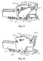
- each detachable connector 5 comprises an electrical connection assembly 7 provided with a connection terminal 9 arranged to cooperate with a conductive electrical wire and a connection socket 11 arranged to cooperate with a complementary socket 3 of the terminal block 1.
- Each detachable connector 5 also comprises an insulating body 13 in which a cavity 15 is formed.
- the cavity 15 defines an opening 17 through a first transverse wall 19 of the insulating body 13.
- the electrical connection assembly 7 is disposed in the cavity 15 at a location of cooperation 21 of the insulating body 13.
- the insulating body 13 comprises a second transverse wall 23 extending opposite the electrical connection assembly 7 and being adjacent at the cooperation location 21.
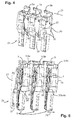
- a row 25 of withdrawable connectors 5 comprises a plurality of assembled withdrawable connectors and a removable closure element 27.
- the row 25 extends in a direction of extension called longitudinal direction 29.
- first transverse wall 19 and the second transverse wall 23 of each withdrawable connector 5 of the row 25 is arranged transversely to the longitudinal direction 29.
- the detachable connectors of a first type 5a and the withdrawable connectors of a second type 5b are differentiated.
- a first type withdrawable connector 5a comprises a first cooperation arrangement 31 arranged to cooperate with a removable closure element 27 and a second cooperation arrangement 33 arranged to cooperate with a second type 5b withdrawable connector.
- the first cooperation arrangement 31a comprises a hook 35 intended to cooperate with a removable closure element 27.
- the hook 35 has a removable fastening orifice 37 formed in the first transverse wall 19 and extending in the longitudinal direction 29.
- the removable fixing orifice 37 is arranged to cooperate with a complementary engagement pad 39 of the closure element 27.
- the first transverse wall 19 has a recess 41 extending in the longitudinal direction 29 towards the second transverse wall 23 at a height h at least equal to the thickness ep of the removable closure element 27.
- the removable closure member 27 allows to close the opening 17 generated by the cavity 15 while not extending longitudinally of the template of the first type of withdrawable connector 5a.
- the second cooperation arrangement 33 comprises a plurality of depressions 43 formed in the second transverse wall 23 and extending in the longitudinal direction 29 from the second transverse wall 23 to the first transverse wall 19.
- a second type plug-in connector 5b comprises a first cooperation arrangement 31b arranged to cooperate with a second cooperation arrangement 33 and also comprises a second cooperation arrangement 33.
- the first cooperating arrangement 31b of the second type plug-in connector 5b comprises a plurality of projections 45 of the first transverse wall 19 extending in the longitudinal direction 29.
- projections 45 are arranged to cooperate with complementary depressions 43 of a second cooperation arrangement 33 in a mortise-type cooperation.
- first engagement arrangement 31b includes a projecting portion 47a and the second engagement arrangement 33 comprises a recessed portion 47b constituting a detent 47.
- first cooperation arrangement 31b and the second cooperation arrangement 33 of removable connectors of the second type 5b comprise projections 45 and recesses 43 of the mortise tenon type and a latching system 47. It should also be noted that the withdrawable connectors of first type 5a also comprise a recessed portion 47b of latching system 47.
- a row 25 of withdrawable connectors 5 comprises a removable closure element 27, a first type withdrawable connector 5a and at least one second type 5b withdrawable connector.
- the removable closure element 27 is always associated with a first type plug-in connector 5a whether to use this connector 5 as an individual connector or to use this connector 5 in a row 25.
- This advantage is related to the arrangement of the stud-like projections 45 on the side of the opening 17 for the removable connectors of the second type 5b.
- the present arrangements allow a reduction in the number of patterns. from three to two.
- the insulating body 13, the first cooperating arrangement 13a, 13b and the second cooperating arrangement 33 may be made in one piece. Reducing the number of models is therefore also advantageous in terms of manufacturing since only two different molds are needed when the single piece is made by molding.
- the invention is not limited to the single embodiment of this plug-in connector and this row of withdrawable connectors, described above as an example, it encompasses all variants of production.
Landscapes
- Connector Housings Or Holding Contact Members (AREA)
Priority Applications (2)
| Application Number | Priority Date | Filing Date | Title |
|---|---|---|---|
| EP15161720.6A EP3076486B1 (de) | 2015-03-30 | 2015-03-30 | Reihe von steckverbindern für anschlussblock |
| CN201610195262.7A CN106025662B (zh) | 2015-03-30 | 2016-03-30 | 用于端子块的可拆卸连接器和可拆卸连接器的排 |
Applications Claiming Priority (1)
| Application Number | Priority Date | Filing Date | Title |
|---|---|---|---|
| EP15161720.6A EP3076486B1 (de) | 2015-03-30 | 2015-03-30 | Reihe von steckverbindern für anschlussblock |
Publications (2)
| Publication Number | Publication Date |
|---|---|
| EP3076486A1 true EP3076486A1 (de) | 2016-10-05 |
| EP3076486B1 EP3076486B1 (de) | 2020-04-22 |
Family
ID=52780941
Family Applications (1)
| Application Number | Title | Priority Date | Filing Date |
|---|---|---|---|
| EP15161720.6A Revoked EP3076486B1 (de) | 2015-03-30 | 2015-03-30 | Reihe von steckverbindern für anschlussblock |
Country Status (2)
| Country | Link |
|---|---|
| EP (1) | EP3076486B1 (de) |
| CN (1) | CN106025662B (de) |
Cited By (2)
| Publication number | Priority date | Publication date | Assignee | Title |
|---|---|---|---|---|
| EP3671963A1 (de) * | 2018-12-19 | 2020-06-24 | Tyco Electronics France SAS | Verbindungsanordnung mit einem entnahmefähigen verbinder und fuss zum zusammenwirken mit dem entnahmefähigen verbinder |
| CN112514170A (zh) * | 2018-08-27 | 2021-03-16 | 欧姆龙株式会社 | 连接器式免螺丝端子台 |
Citations (1)
| Publication number | Priority date | Publication date | Assignee | Title |
|---|---|---|---|---|
| WO2014161847A1 (de) * | 2013-04-05 | 2014-10-09 | Weidmüller Interface GmbH & Co. KG | Steckvorrichtung für einen federkraftanschluss |
Family Cites Families (8)
| Publication number | Priority date | Publication date | Assignee | Title |
|---|---|---|---|---|
| DE19506859A1 (de) * | 1995-02-15 | 1996-08-22 | Wago Verwaltungs Gmbh | Elektr. Steckverbinder |
| DE19535822A1 (de) * | 1995-09-26 | 1997-03-27 | Amp Holland | Anordnung zum Verbinden von einem elektrischen Stecker mit einem komplementären Stecker |
| ITBG20050023A1 (it) | 2005-05-13 | 2006-11-14 | Abb Service Srl | Dispositivo di connessione per interruttori di bassa tensione |
| US8162689B2 (en) | 2005-08-29 | 2012-04-24 | Phoenix Contact Gmbh & Co., Kg | Clamping device for connecting a conductor without stripping the insulation |
| DE102006003064B4 (de) | 2006-01-20 | 2010-04-15 | Phoenix Contact Gmbh & Co. Kg | Elektrischer Reihenklemmenblock |
| DE102006019160B4 (de) | 2006-04-21 | 2008-02-28 | Phoenix Contact Gmbh & Co. Kg | Steckverbinder mit Kurzschlußkontakten |
| US8469734B2 (en) * | 2010-04-20 | 2013-06-25 | Liang Light Chen | Retainer system for electric cable couplers |
| DE102011115637B4 (de) | 2011-06-21 | 2014-03-27 | Phoenix Contact Gmbh & Co. Kg | Elektrische Anschlussklemme |
-
2015
- 2015-03-30 EP EP15161720.6A patent/EP3076486B1/de not_active Revoked
-
2016
- 2016-03-30 CN CN201610195262.7A patent/CN106025662B/zh active Active
Patent Citations (1)
| Publication number | Priority date | Publication date | Assignee | Title |
|---|---|---|---|---|
| WO2014161847A1 (de) * | 2013-04-05 | 2014-10-09 | Weidmüller Interface GmbH & Co. KG | Steckvorrichtung für einen federkraftanschluss |
Cited By (2)
| Publication number | Priority date | Publication date | Assignee | Title |
|---|---|---|---|---|
| CN112514170A (zh) * | 2018-08-27 | 2021-03-16 | 欧姆龙株式会社 | 连接器式免螺丝端子台 |
| EP3671963A1 (de) * | 2018-12-19 | 2020-06-24 | Tyco Electronics France SAS | Verbindungsanordnung mit einem entnahmefähigen verbinder und fuss zum zusammenwirken mit dem entnahmefähigen verbinder |
Also Published As
| Publication number | Publication date |
|---|---|
| CN106025662A (zh) | 2016-10-12 |
| EP3076486B1 (de) | 2020-04-22 |
| CN106025662B (zh) | 2021-03-16 |
Similar Documents
| Publication | Publication Date | Title |
|---|---|---|
| FR3029703A1 (fr) | Dispositif de prise electrique comprenant au moins un element de verrouillage et deverrouillage | |
| EP1151499B1 (de) | Elektrische schalteranordnung | |
| FR2901922A1 (fr) | Connecteur electrique a grande force de maintien des contacts. | |
| EP0123590A1 (de) | Verbinder | |
| EP2312700A1 (de) | Teil eines elektrischen Verbinders und damit electrischer Verbinder. | |
| FR2969400A1 (fr) | Connecteur pour carte de circuit imprime | |
| EP3076486B1 (de) | Reihe von steckverbindern für anschlussblock | |
| EP0726624B1 (de) | Verbindungsanordnung | |
| EP1026782B1 (de) | Verbindungsblock für elektrische Geräte | |
| FR3018143A3 (fr) | Element adaptateur pour differentes prises de voix et donnees et plaque decorative qui l'heberge | |
| FR2750261A1 (fr) | Structure de connexion pour un corps de circuit plat et un connecteur | |
| BE1022438B1 (fr) | Dispositif formant caniveau a securite amelioree | |
| FR2953905A1 (fr) | Boitier de suspension de luminaire | |
| FR2917911A1 (fr) | Coffret destine a recevoir un appareillage electrique | |
| EP1107363A1 (de) | Monopolarer Modularerverteiler | |
| EP3553904B1 (de) | Befestigungsvorrichtung eines steuer- und/oder signalisierungsorgans | |
| EP2874244B1 (de) | Elektrischer Anschluss mit modulierbarer Kodierung | |
| FR2714540A1 (fr) | Socle multiple pour prise de courant. | |
| EP0076183B1 (de) | Elektrische Verteilungsvorrichtung | |
| EP3389141B1 (de) | Vorrichtung zur mechanischen halterung eines leitungsdrahtbündels | |
| FR3038461B1 (fr) | Systeme de verrouillage d'un socle d'emboitement d'une prise avec une prise, socle d'emboitement et prise associes | |
| FR2772523A3 (fr) | Dispositif anti-enclenchement pour connecteurs electriques multipolaires | |
| EP0459860A2 (de) | Modulklemmleiste für elektrische Verbindungen | |
| FR3079063A1 (fr) | Ensemble d'elements permettant la constitution d'un feu de signalisation a au moins deux feux | |
| BE1022597B1 (fr) | Boîtier électrique |
Legal Events
| Date | Code | Title | Description |
|---|---|---|---|
| PUAI | Public reference made under article 153(3) epc to a published international application that has entered the european phase |
Free format text: ORIGINAL CODE: 0009012 |
|
| AK | Designated contracting states |
Kind code of ref document: A1 Designated state(s): AL AT BE BG CH CY CZ DE DK EE ES FI FR GB GR HR HU IE IS IT LI LT LU LV MC MK MT NL NO PL PT RO RS SE SI SK SM TR |
|
| AX | Request for extension of the european patent |
Extension state: BA ME |
|
| STAA | Information on the status of an ep patent application or granted ep patent |
Free format text: STATUS: REQUEST FOR EXAMINATION WAS MADE |
|
| RAP1 | Party data changed (applicant data changed or rights of an application transferred) |
Owner name: ABB SCHWEIZ AG |
|
| 17P | Request for examination filed |
Effective date: 20170323 |
|
| RBV | Designated contracting states (corrected) |
Designated state(s): AL AT BE BG CH CY CZ DE DK EE ES FI FR GB GR HR HU IE IS IT LI LT LU LV MC MK MT NL NO PL PT RO RS SE SI SK SM TR |
|
| STAA | Information on the status of an ep patent application or granted ep patent |
Free format text: STATUS: EXAMINATION IS IN PROGRESS |
|
| 17Q | First examination report despatched |
Effective date: 20180319 |
|
| RAP1 | Party data changed (applicant data changed or rights of an application transferred) |
Owner name: TYCO ELECTRONICS SERVICES GMBH |
|
| GRAP | Despatch of communication of intention to grant a patent |
Free format text: ORIGINAL CODE: EPIDOSNIGR1 |
|
| STAA | Information on the status of an ep patent application or granted ep patent |
Free format text: STATUS: GRANT OF PATENT IS INTENDED |
|
| RIC1 | Information provided on ipc code assigned before grant |
Ipc: H01R 31/06 20060101ALI20191112BHEP Ipc: H01R 9/24 20060101AFI20191112BHEP Ipc: H01R 101/00 20060101ALN20191112BHEP Ipc: H01R 4/48 20060101ALN20191112BHEP Ipc: H01R 13/506 20060101ALN20191112BHEP Ipc: H01R 4/24 20180101ALN20191112BHEP Ipc: H01R 9/26 20060101ALN20191112BHEP |
|
| INTG | Intention to grant announced |
Effective date: 20191127 |
|
| RAP1 | Party data changed (applicant data changed or rights of an application transferred) |
Owner name: TE CONNECTIVITY SERVICES GMBH |
|
| GRAS | Grant fee paid |
Free format text: ORIGINAL CODE: EPIDOSNIGR3 |
|
| GRAA | (expected) grant |
Free format text: ORIGINAL CODE: 0009210 |
|
| STAA | Information on the status of an ep patent application or granted ep patent |
Free format text: STATUS: THE PATENT HAS BEEN GRANTED |
|
| AK | Designated contracting states |
Kind code of ref document: B1 Designated state(s): AL AT BE BG CH CY CZ DE DK EE ES FI FR GB GR HR HU IE IS IT LI LT LU LV MC MK MT NL NO PL PT RO RS SE SI SK SM TR |
|
| REG | Reference to a national code |
Ref country code: CH Ref legal event code: EP |
|
| REG | Reference to a national code |
Ref country code: IE Ref legal event code: FG4D Free format text: LANGUAGE OF EP DOCUMENT: FRENCH |
|
| REG | Reference to a national code |
Ref country code: DE Ref legal event code: R096 Ref document number: 602015050991 Country of ref document: DE |
|
| REG | Reference to a national code |
Ref country code: AT Ref legal event code: REF Ref document number: 1261379 Country of ref document: AT Kind code of ref document: T Effective date: 20200515 |
|
| REG | Reference to a national code |
Ref country code: LT Ref legal event code: MG4D |
|
| REG | Reference to a national code |
Ref country code: NL Ref legal event code: MP Effective date: 20200422 |
|
| PG25 | Lapsed in a contracting state [announced via postgrant information from national office to epo] |
Ref country code: PT Free format text: LAPSE BECAUSE OF FAILURE TO SUBMIT A TRANSLATION OF THE DESCRIPTION OR TO PAY THE FEE WITHIN THE PRESCRIBED TIME-LIMIT Effective date: 20200824 Ref country code: FI Free format text: LAPSE BECAUSE OF FAILURE TO SUBMIT A TRANSLATION OF THE DESCRIPTION OR TO PAY THE FEE WITHIN THE PRESCRIBED TIME-LIMIT Effective date: 20200422 Ref country code: LT Free format text: LAPSE BECAUSE OF FAILURE TO SUBMIT A TRANSLATION OF THE DESCRIPTION OR TO PAY THE FEE WITHIN THE PRESCRIBED TIME-LIMIT Effective date: 20200422 Ref country code: NL Free format text: LAPSE BECAUSE OF FAILURE TO SUBMIT A TRANSLATION OF THE DESCRIPTION OR TO PAY THE FEE WITHIN THE PRESCRIBED TIME-LIMIT Effective date: 20200422 Ref country code: SE Free format text: LAPSE BECAUSE OF FAILURE TO SUBMIT A TRANSLATION OF THE DESCRIPTION OR TO PAY THE FEE WITHIN THE PRESCRIBED TIME-LIMIT Effective date: 20200422 Ref country code: IS Free format text: LAPSE BECAUSE OF FAILURE TO SUBMIT A TRANSLATION OF THE DESCRIPTION OR TO PAY THE FEE WITHIN THE PRESCRIBED TIME-LIMIT Effective date: 20200822 Ref country code: GR Free format text: LAPSE BECAUSE OF FAILURE TO SUBMIT A TRANSLATION OF THE DESCRIPTION OR TO PAY THE FEE WITHIN THE PRESCRIBED TIME-LIMIT Effective date: 20200723 Ref country code: NO Free format text: LAPSE BECAUSE OF FAILURE TO SUBMIT A TRANSLATION OF THE DESCRIPTION OR TO PAY THE FEE WITHIN THE PRESCRIBED TIME-LIMIT Effective date: 20200722 |
|
| REG | Reference to a national code |
Ref country code: AT Ref legal event code: MK05 Ref document number: 1261379 Country of ref document: AT Kind code of ref document: T Effective date: 20200422 |
|
| RAP2 | Party data changed (patent owner data changed or rights of a patent transferred) |
Owner name: TE CONNECTIVITY SERVICES GMBH |
|
| PG25 | Lapsed in a contracting state [announced via postgrant information from national office to epo] |
Ref country code: HR Free format text: LAPSE BECAUSE OF FAILURE TO SUBMIT A TRANSLATION OF THE DESCRIPTION OR TO PAY THE FEE WITHIN THE PRESCRIBED TIME-LIMIT Effective date: 20200422 Ref country code: RS Free format text: LAPSE BECAUSE OF FAILURE TO SUBMIT A TRANSLATION OF THE DESCRIPTION OR TO PAY THE FEE WITHIN THE PRESCRIBED TIME-LIMIT Effective date: 20200422 Ref country code: BG Free format text: LAPSE BECAUSE OF FAILURE TO SUBMIT A TRANSLATION OF THE DESCRIPTION OR TO PAY THE FEE WITHIN THE PRESCRIBED TIME-LIMIT Effective date: 20200722 Ref country code: LV Free format text: LAPSE BECAUSE OF FAILURE TO SUBMIT A TRANSLATION OF THE DESCRIPTION OR TO PAY THE FEE WITHIN THE PRESCRIBED TIME-LIMIT Effective date: 20200422 |
|
| PG25 | Lapsed in a contracting state [announced via postgrant information from national office to epo] |
Ref country code: AL Free format text: LAPSE BECAUSE OF FAILURE TO SUBMIT A TRANSLATION OF THE DESCRIPTION OR TO PAY THE FEE WITHIN THE PRESCRIBED TIME-LIMIT Effective date: 20200422 |
|
| REG | Reference to a national code |
Ref country code: DE Ref legal event code: R026 Ref document number: 602015050991 Country of ref document: DE |
|
| PG25 | Lapsed in a contracting state [announced via postgrant information from national office to epo] |
Ref country code: ES Free format text: LAPSE BECAUSE OF FAILURE TO SUBMIT A TRANSLATION OF THE DESCRIPTION OR TO PAY THE FEE WITHIN THE PRESCRIBED TIME-LIMIT Effective date: 20200422 Ref country code: IT Free format text: LAPSE BECAUSE OF FAILURE TO SUBMIT A TRANSLATION OF THE DESCRIPTION OR TO PAY THE FEE WITHIN THE PRESCRIBED TIME-LIMIT Effective date: 20200422 Ref country code: RO Free format text: LAPSE BECAUSE OF FAILURE TO SUBMIT A TRANSLATION OF THE DESCRIPTION OR TO PAY THE FEE WITHIN THE PRESCRIBED TIME-LIMIT Effective date: 20200422 Ref country code: CZ Free format text: LAPSE BECAUSE OF FAILURE TO SUBMIT A TRANSLATION OF THE DESCRIPTION OR TO PAY THE FEE WITHIN THE PRESCRIBED TIME-LIMIT Effective date: 20200422 Ref country code: AT Free format text: LAPSE BECAUSE OF FAILURE TO SUBMIT A TRANSLATION OF THE DESCRIPTION OR TO PAY THE FEE WITHIN THE PRESCRIBED TIME-LIMIT Effective date: 20200422 Ref country code: SM Free format text: LAPSE BECAUSE OF FAILURE TO SUBMIT A TRANSLATION OF THE DESCRIPTION OR TO PAY THE FEE WITHIN THE PRESCRIBED TIME-LIMIT Effective date: 20200422 Ref country code: EE Free format text: LAPSE BECAUSE OF FAILURE TO SUBMIT A TRANSLATION OF THE DESCRIPTION OR TO PAY THE FEE WITHIN THE PRESCRIBED TIME-LIMIT Effective date: 20200422 Ref country code: DK Free format text: LAPSE BECAUSE OF FAILURE TO SUBMIT A TRANSLATION OF THE DESCRIPTION OR TO PAY THE FEE WITHIN THE PRESCRIBED TIME-LIMIT Effective date: 20200422 |
|
| PLBI | Opposition filed |
Free format text: ORIGINAL CODE: 0009260 |
|
| PLAX | Notice of opposition and request to file observation + time limit sent |
Free format text: ORIGINAL CODE: EPIDOSNOBS2 |
|
| PG25 | Lapsed in a contracting state [announced via postgrant information from national office to epo] |
Ref country code: SK Free format text: LAPSE BECAUSE OF FAILURE TO SUBMIT A TRANSLATION OF THE DESCRIPTION OR TO PAY THE FEE WITHIN THE PRESCRIBED TIME-LIMIT Effective date: 20200422 Ref country code: PL Free format text: LAPSE BECAUSE OF FAILURE TO SUBMIT A TRANSLATION OF THE DESCRIPTION OR TO PAY THE FEE WITHIN THE PRESCRIBED TIME-LIMIT Effective date: 20200422 |
|
| 26 | Opposition filed |
Opponent name: PHOENIX CONTACT GMBH & CO. KG Effective date: 20210122 |
|
| PG25 | Lapsed in a contracting state [announced via postgrant information from national office to epo] |
Ref country code: SI Free format text: LAPSE BECAUSE OF FAILURE TO SUBMIT A TRANSLATION OF THE DESCRIPTION OR TO PAY THE FEE WITHIN THE PRESCRIBED TIME-LIMIT Effective date: 20200422 |
|
| PLBB | Reply of patent proprietor to notice(s) of opposition received |
Free format text: ORIGINAL CODE: EPIDOSNOBS3 |
|
| PG25 | Lapsed in a contracting state [announced via postgrant information from national office to epo] |
Ref country code: MC Free format text: LAPSE BECAUSE OF FAILURE TO SUBMIT A TRANSLATION OF THE DESCRIPTION OR TO PAY THE FEE WITHIN THE PRESCRIBED TIME-LIMIT Effective date: 20200422 |
|
| REG | Reference to a national code |
Ref country code: CH Ref legal event code: PL |
|
| REG | Reference to a national code |
Ref country code: BE Ref legal event code: MM Effective date: 20210331 |
|
| PG25 | Lapsed in a contracting state [announced via postgrant information from national office to epo] |
Ref country code: IE Free format text: LAPSE BECAUSE OF NON-PAYMENT OF DUE FEES Effective date: 20210330 Ref country code: LI Free format text: LAPSE BECAUSE OF NON-PAYMENT OF DUE FEES Effective date: 20210331 Ref country code: LU Free format text: LAPSE BECAUSE OF NON-PAYMENT OF DUE FEES Effective date: 20210330 Ref country code: CH Free format text: LAPSE BECAUSE OF NON-PAYMENT OF DUE FEES Effective date: 20210331 |
|
| PG25 | Lapsed in a contracting state [announced via postgrant information from national office to epo] |
Ref country code: BE Free format text: LAPSE BECAUSE OF NON-PAYMENT OF DUE FEES Effective date: 20210331 |
|
| PLCK | Communication despatched that opposition was rejected |
Free format text: ORIGINAL CODE: EPIDOSNREJ1 |
|
| APBM | Appeal reference recorded |
Free format text: ORIGINAL CODE: EPIDOSNREFNO |
|
| APBP | Date of receipt of notice of appeal recorded |
Free format text: ORIGINAL CODE: EPIDOSNNOA2O |
|
| APAH | Appeal reference modified |
Free format text: ORIGINAL CODE: EPIDOSCREFNO |
|
| RAP2 | Party data changed (patent owner data changed or rights of a patent transferred) |
Owner name: TE CONNECTIVITY SOLUTIONS GMBH |
|
| APBQ | Date of receipt of statement of grounds of appeal recorded |
Free format text: ORIGINAL CODE: EPIDOSNNOA3O |
|
| PG25 | Lapsed in a contracting state [announced via postgrant information from national office to epo] |
Ref country code: HU Free format text: LAPSE BECAUSE OF FAILURE TO SUBMIT A TRANSLATION OF THE DESCRIPTION OR TO PAY THE FEE WITHIN THE PRESCRIBED TIME-LIMIT; INVALID AB INITIO Effective date: 20150330 |
|
| PG25 | Lapsed in a contracting state [announced via postgrant information from national office to epo] |
Ref country code: CY Free format text: LAPSE BECAUSE OF FAILURE TO SUBMIT A TRANSLATION OF THE DESCRIPTION OR TO PAY THE FEE WITHIN THE PRESCRIBED TIME-LIMIT Effective date: 20200422 |
|
| PG25 | Lapsed in a contracting state [announced via postgrant information from national office to epo] |
Ref country code: MK Free format text: LAPSE BECAUSE OF FAILURE TO SUBMIT A TRANSLATION OF THE DESCRIPTION OR TO PAY THE FEE WITHIN THE PRESCRIBED TIME-LIMIT Effective date: 20200422 |
|
| APAH | Appeal reference modified |
Free format text: ORIGINAL CODE: EPIDOSCREFNO |
|
| APAH | Appeal reference modified |
Free format text: ORIGINAL CODE: EPIDOSCREFNO |
|
| PG25 | Lapsed in a contracting state [announced via postgrant information from national office to epo] |
Ref country code: MT Free format text: LAPSE BECAUSE OF FAILURE TO SUBMIT A TRANSLATION OF THE DESCRIPTION OR TO PAY THE FEE WITHIN THE PRESCRIBED TIME-LIMIT Effective date: 20200422 |
|
| PGFP | Annual fee paid to national office [announced via postgrant information from national office to epo] |
Ref country code: DE Payment date: 20241231 Year of fee payment: 11 |
|
| PGFP | Annual fee paid to national office [announced via postgrant information from national office to epo] |
Ref country code: FR Payment date: 20250210 Year of fee payment: 11 |
|
| PGFP | Annual fee paid to national office [announced via postgrant information from national office to epo] |
Ref country code: GB Payment date: 20250102 Year of fee payment: 11 |
|
| REG | Reference to a national code |
Ref country code: DE Ref legal event code: R064 Ref document number: 602015050991 Country of ref document: DE Ref country code: DE Ref legal event code: R103 Ref document number: 602015050991 Country of ref document: DE |
|
| APBU | Appeal procedure closed |
Free format text: ORIGINAL CODE: EPIDOSNNOA9O |
|
| RDAF | Communication despatched that patent is revoked |
Free format text: ORIGINAL CODE: EPIDOSNREV1 |
|
| RDAG | Patent revoked |
Free format text: ORIGINAL CODE: 0009271 |
|
| STAA | Information on the status of an ep patent application or granted ep patent |
Free format text: STATUS: PATENT REVOKED |
|
| REG | Reference to a national code |
Ref country code: CH Ref legal event code: PL |
|
| REG | Reference to a national code |
Ref country code: GB Ref legal event code: 732E Free format text: REGISTERED BETWEEN 20250731 AND 20250806 |
|
| 27W | Patent revoked |
Effective date: 20250729 |
|
| GBPR | Gb: patent revoked under art. 102 of the ep convention designating the uk as contracting state |
Effective date: 20250729 |
|
| PG25 | Lapsed in a contracting state [announced via postgrant information from national office to epo] |
Ref country code: TR Free format text: LAPSE BECAUSE OF FAILURE TO SUBMIT A TRANSLATION OF THE DESCRIPTION OR TO PAY THE FEE WITHIN THE PRESCRIBED TIME-LIMIT Effective date: 20200422 |