EP3076517B1 - Système de transmission de puissance - Google Patents
Système de transmission de puissance Download PDFInfo
- Publication number
- EP3076517B1 EP3076517B1 EP16158312.5A EP16158312A EP3076517B1 EP 3076517 B1 EP3076517 B1 EP 3076517B1 EP 16158312 A EP16158312 A EP 16158312A EP 3076517 B1 EP3076517 B1 EP 3076517B1
- Authority
- EP
- European Patent Office
- Prior art keywords
- power
- balloon
- power transmission
- underwater
- resonance coil
- Prior art date
- Legal status (The legal status is an assumption and is not a legal conclusion. Google has not performed a legal analysis and makes no representation as to the accuracy of the status listed.)
- Active
Links
Images



Classifications
-
- H—ELECTRICITY
- H02—GENERATION; CONVERSION OR DISTRIBUTION OF ELECTRIC POWER
- H02J—ELECTRIC POWER NETWORKS; CIRCUIT ARRANGEMENTS OR SYSTEMS FOR SUPPLYING OR DISTRIBUTING ELECTRIC POWER; SYSTEMS FOR STORING ELECTRIC ENERGY
- H02J7/00—Circuit arrangements for charging or discharging batteries or for supplying loads from batteries
- H02J7/70—Circuit arrangements for charging or discharging batteries or for supplying loads from batteries characterised by the mechanical construction
-
- B—PERFORMING OPERATIONS; TRANSPORTING
- B63—SHIPS OR OTHER WATERBORNE VESSELS; RELATED EQUIPMENT
- B63G—OFFENSIVE OR DEFENSIVE ARRANGEMENTS ON VESSELS; MINE-LAYING; MINE-SWEEPING; SUBMARINES; AIRCRAFT CARRIERS
- B63G8/00—Underwater vessels, e.g. submarines; Equipment specially adapted therefor
- B63G8/001—Underwater vessels adapted for special purposes, e.g. unmanned underwater vessels; Equipment specially adapted therefor, e.g. docking stations
-
- B—PERFORMING OPERATIONS; TRANSPORTING
- B60—VEHICLES IN GENERAL
- B60L—PROPULSION OF ELECTRICALLY-PROPELLED VEHICLES; SUPPLYING ELECTRIC POWER FOR AUXILIARY EQUIPMENT OF ELECTRICALLY-PROPELLED VEHICLES; ELECTRODYNAMIC BRAKE SYSTEMS FOR VEHICLES IN GENERAL; MAGNETIC SUSPENSION OR LEVITATION FOR VEHICLES; MONITORING OPERATING VARIABLES OF ELECTRICALLY-PROPELLED VEHICLES; ELECTRIC SAFETY DEVICES FOR ELECTRICALLY-PROPELLED VEHICLES
- B60L53/00—Methods of charging batteries, specially adapted for electric vehicles; Charging stations or on-board charging equipment therefor; Exchange of energy storage elements in electric vehicles
- B60L53/10—Methods of charging batteries, specially adapted for electric vehicles; Charging stations or on-board charging equipment therefor; Exchange of energy storage elements in electric vehicles characterised by the energy transfer between the charging station and the vehicle
- B60L53/12—Inductive energy transfer
-
- B—PERFORMING OPERATIONS; TRANSPORTING
- B63—SHIPS OR OTHER WATERBORNE VESSELS; RELATED EQUIPMENT
- B63G—OFFENSIVE OR DEFENSIVE ARRANGEMENTS ON VESSELS; MINE-LAYING; MINE-SWEEPING; SUBMARINES; AIRCRAFT CARRIERS
- B63G8/00—Underwater vessels, e.g. submarines; Equipment specially adapted therefor
- B63G8/08—Propulsion
-
- G—PHYSICS
- G01—MEASURING; TESTING
- G01N—INVESTIGATING OR ANALYSING MATERIALS BY DETERMINING THEIR CHEMICAL OR PHYSICAL PROPERTIES
- G01N33/00—Investigating or analysing materials by specific methods not covered by groups G01N1/00 - G01N31/00
- G01N33/18—Water
- G01N33/1886—Water using probes, e.g. submersible probes, buoys
-
- H—ELECTRICITY
- H02—GENERATION; CONVERSION OR DISTRIBUTION OF ELECTRIC POWER
- H02J—ELECTRIC POWER NETWORKS; CIRCUIT ARRANGEMENTS OR SYSTEMS FOR SUPPLYING OR DISTRIBUTING ELECTRIC POWER; SYSTEMS FOR STORING ELECTRIC ENERGY
- H02J50/00—Circuit arrangements or systems for wireless supply or distribution of electric power
- H02J50/005—Mechanical details of housing or structure aiming to accommodate the power transfer means, e.g. mechanical integration of coils, antennas or transducers into emitting or receiving devices
-
- H—ELECTRICITY
- H02—GENERATION; CONVERSION OR DISTRIBUTION OF ELECTRIC POWER
- H02J—ELECTRIC POWER NETWORKS; CIRCUIT ARRANGEMENTS OR SYSTEMS FOR SUPPLYING OR DISTRIBUTING ELECTRIC POWER; SYSTEMS FOR STORING ELECTRIC ENERGY
- H02J50/00—Circuit arrangements or systems for wireless supply or distribution of electric power
- H02J50/10—Circuit arrangements or systems for wireless supply or distribution of electric power using inductive coupling
- H02J50/12—Circuit arrangements or systems for wireless supply or distribution of electric power using inductive coupling of the resonant type
-
- H—ELECTRICITY
- H02—GENERATION; CONVERSION OR DISTRIBUTION OF ELECTRIC POWER
- H02J—ELECTRIC POWER NETWORKS; CIRCUIT ARRANGEMENTS OR SYSTEMS FOR SUPPLYING OR DISTRIBUTING ELECTRIC POWER; SYSTEMS FOR STORING ELECTRIC ENERGY
- H02J50/00—Circuit arrangements or systems for wireless supply or distribution of electric power
- H02J50/90—Circuit arrangements or systems for wireless supply or distribution of electric power involving detection or optimisation of position, e.g. alignment
-
- B—PERFORMING OPERATIONS; TRANSPORTING
- B60—VEHICLES IN GENERAL
- B60L—PROPULSION OF ELECTRICALLY-PROPELLED VEHICLES; SUPPLYING ELECTRIC POWER FOR AUXILIARY EQUIPMENT OF ELECTRICALLY-PROPELLED VEHICLES; ELECTRODYNAMIC BRAKE SYSTEMS FOR VEHICLES IN GENERAL; MAGNETIC SUSPENSION OR LEVITATION FOR VEHICLES; MONITORING OPERATING VARIABLES OF ELECTRICALLY-PROPELLED VEHICLES; ELECTRIC SAFETY DEVICES FOR ELECTRICALLY-PROPELLED VEHICLES
- B60L2200/00—Type of vehicles
- B60L2200/32—Waterborne vessels
-
- B—PERFORMING OPERATIONS; TRANSPORTING
- B63—SHIPS OR OTHER WATERBORNE VESSELS; RELATED EQUIPMENT
- B63B—SHIPS OR OTHER WATERBORNE VESSELS; EQUIPMENT FOR SHIPPING
- B63B2211/00—Applications
- B63B2211/02—Oceanography
-
- B—PERFORMING OPERATIONS; TRANSPORTING
- B63—SHIPS OR OTHER WATERBORNE VESSELS; RELATED EQUIPMENT
- B63G—OFFENSIVE OR DEFENSIVE ARRANGEMENTS ON VESSELS; MINE-LAYING; MINE-SWEEPING; SUBMARINES; AIRCRAFT CARRIERS
- B63G8/00—Underwater vessels, e.g. submarines; Equipment specially adapted therefor
- B63G8/001—Underwater vessels adapted for special purposes, e.g. unmanned underwater vessels; Equipment specially adapted therefor, e.g. docking stations
- B63G2008/002—Underwater vessels adapted for special purposes, e.g. unmanned underwater vessels; Equipment specially adapted therefor, e.g. docking stations unmanned
- B63G2008/008—Docking stations for unmanned underwater vessels, or the like
-
- H—ELECTRICITY
- H02—GENERATION; CONVERSION OR DISTRIBUTION OF ELECTRIC POWER
- H02J—ELECTRIC POWER NETWORKS; CIRCUIT ARRANGEMENTS OR SYSTEMS FOR SUPPLYING OR DISTRIBUTING ELECTRIC POWER; SYSTEMS FOR STORING ELECTRIC ENERGY
- H02J2105/00—Networks for supplying or distributing electric power characterised by their spatial reach or by the load
- H02J2105/30—Networks for supplying or distributing electric power characterised by their spatial reach or by the load the load networks being external to vehicles, i.e. exchanging power with vehicles
- H02J2105/31—Networks for supplying or distributing electric power characterised by their spatial reach or by the load the load networks being external to vehicles, i.e. exchanging power with vehicles for ships or vessels
-
- H—ELECTRICITY
- H02—GENERATION; CONVERSION OR DISTRIBUTION OF ELECTRIC POWER
- H02J—ELECTRIC POWER NETWORKS; CIRCUIT ARRANGEMENTS OR SYSTEMS FOR SUPPLYING OR DISTRIBUTING ELECTRIC POWER; SYSTEMS FOR STORING ELECTRIC ENERGY
- H02J50/00—Circuit arrangements or systems for wireless supply or distribution of electric power
- H02J50/40—Circuit arrangements or systems for wireless supply or distribution of electric power using two or more transmitting or receiving devices
- H02J50/402—Circuit arrangements or systems for wireless supply or distribution of electric power using two or more transmitting or receiving devices the two or more transmitting or the two or more receiving devices being integrated in the same unit, e.g. power mats with several coils or antennas with several sub-antennas
Definitions
- the present invention relates to a power transmission system.
- Patent document 1 see below, technology is disclosed in which a battery that is installed in an underwater station that collects data relating to the water quality of sea water is charged by an underwater robot that travels through the water using a wireless power supply system (in particular, an electromagnetic induction system).
- a wireless power supply system in particular, an electromagnetic induction system
- the present invention was conceived in view of the above-described circumstances and it is an object thereof to provide a power transmission system that makes it possible to achieve underwater power transmissions at low cost between a power-transmitting device and a power-receiving device of which at least one is capable of moving freely underwater.
- the power-transmitting device and the power-receiving device are each provided with a resonance coil that performs the power transmission wirelessly underwater by means of magnetic field resonance.
- At least one of the power-transmitting device and the power-receiving device is provided with a balloon that internally houses the resonance coil of its host device.
- At least one of the power-transmitting device and the power-receiving device is provided with a balloon control mechanism that, during a power transmission, causes the balloon to inflate, and at other times, causes the balloon to be deflated.
- the power-receiving device is an autonomous underwater vehicle that collects water quality data as it moves through the water under battery power.
- the power-transmitting device is an underwater base station that is installed in a predetermined location underwater and is connected by a cable to an on-land electrical power system, and receives from the electrical power system a supply of power that is to be transmitted to the autonomous underwater vehicle.
- the autonomous underwater vehicle wirelessly transmits the water quality data to the underwater base station during a power transmission.
- the underwater base station is connected by cable to an on-land water quality data control device, and transmits the water quality data that it receives from the autonomous underwater vehicle by cable to the water quality data control device.
- a magnetic field resonance system is employed for underwater power transmissions between a power-transmitting device and a power-receiving device.
- this magnetic field resonance system is largely unaffected by positional shifting of the resonance coils that are provided in both the power-transmitting device and the power-receiving device (i.e., is tolerant of positional shift), and is able to perform power transmissions highly efficiently and over long distances using only a weak magnetic field.
- a high-accuracy positioning mechanism such as is used in the conventional technology which employs an electromagnetic induction system is rendered unnecessary.
- at least one of the resonance coils of the power-transmitting device and the power-receiving device is covered by a balloon.
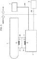
- FIG. 1 is a schematic structural view of a power transmission system A according to the present embodiment.
- the power transmission system A is provided with an underwater base station 1 (i.e., a power-transmitting device) that is installed in a predetermined underwater location, and an autonomous underwater vehicle 2 (i.e., a power-receiving device) that is able to move freely underwater by means of battery power, and with an electrical power system 3 that is installed on land.
- an underwater base station 1 i.e., a power-transmitting device
- an autonomous underwater vehicle 2 i.e., a power-receiving device
- the underwater base station 1 is connected via a power supply cable 100 to the on-land electrical power system 3, and wirelessly transmits (i.e., supplies) AC power (for example, 100 V single-phase power having a frequency of 50 or 60 Hz) that is supplied from the electrical power system 3 to the autonomous underwater vehicle 2 by means of magnetic field resonance.
- the underwater base station 1 is provided with an AC/AC converter 11, a power transmission resonance coil 12, a power transmission balloon 13, a power transmission balloon control mechanism 14, a power supply circuit 15, and a base station control device 16.
- the AC/AC converter 11 converts AC power that is supplied via the power supply cable100 from the on-land electrical power system 3 into AC power that has a predetermined voltage and a predetermined frequency that are suitable for a power transmission via magnetic field resonance.
- the AC/AC converter 11 outputs the converted AC power to the power transmission resonance coil 12.
- the power transmission resonance coil 12 is a spirally-wound helical coil that is used to transmit the AC power input from the AC/AC converter 11 wirelessly by means of magnetic field resonance.
- the power transmission resonance coil 12 is installed such that it protrudes above the underwater base station 1.
- An LC resonance circuit is formed by the power transmission resonance coil 12 and by a capacitor (not shown). Note that it is possible to use the parasitic capacity of the helical coil as the capacitor that is used to form the LC resonant circuit, or alternatively, it is also possible to provide a separate capacitor element. Moreover, it is also possible to provide a core that is formed from a material having high magnetic permeability such as ferrite inside the coil portion of the helical coil.
- the power transmission balloon 13 is provided on an external wall surface of the underwater base station 1 so as to house inside itself the power transmission resonance coil 12.
- the power transmission balloon 13 is able to inflate and deflate freely.
- FIG. 1 a state is shown in which the power transmission balloon 13 is deflated.
- the power transmission balloon control mechanism 14 inflates the power transmission balloon 13 during a power transmission, and deflates the power transmission balloon 13 during other times (i.e., times when power is not being transmitted). Specifically, the power transmission balloon control mechanism 14 causes the power transmission balloon 13 to be inflated by feeding gas to the interior of the power transmission balloon 13 via a gas tube 14a. In contrast, the power transmission balloon control mechanism 14 causes the power transmission balloon 13 to be deflated by suctioning gas from the interior of the power transmission balloon 13 via the gas tube 14a.
- side surfaces of the balloons prefferably be structured in the form of a bellows such that, when gas is being supplied to the interior of a balloon, the balloon inflates so as to fill the space between the power transmission coil and the power reception coil, but with only a small amount of inflation in the side surface direction of each coil.
- an inert gas such as nitrogen
- dry air may also be used.
- a non-corrosive organic material in liquid form, or water with a low content of ions or impurities (for example, water from which impurities have been removed by an ion-exchange resin).
- the power supply circuit 15 uses AC power that is supplied via the power supply cable 100 from the on-land electrical power system 3, and generates power supply voltage for use inside the underwater base station 1.
- the power supply circuit 15 outputs the generated power supply voltage to the base station control unit 16 and the power transmission balloon control mechanism 14.
- the base station control unit 16 is provided with a microprocessor and memory and the like, and, in accordance with control programs that have been stored in advance in its memory, controls the AC/AC converter 11 and the power transmission balloon control mechanism 14 during the transmission of power to the autonomous underwater vehicle 2.
- the autonomous underwater vehicle 2 collects data relating to water quality (hereinafter, this is expressed as 'water quality data') while traveling through the water by battery power, and when its battery is being recharged, receives AC power from the underwater base station 1 by means of magnetic field resonance.
- the autonomous underwater vehicle 2 is provided with a power reception resonance coil 21, a rectifier circuit 22, a charging circuit 23, a battery 24, a propulsion/steering mechanism 25, a water quality sensor 26, a power reception balloon 27, a power reception balloon control mechanism 28, and an autonomous vehicle control unit 29.
- the power reception resonance coil 21 is a spirally-wound helical coil that is used to receive AC power input from the power transmission resonance coil 12 of the underwater base station 1 wirelessly.
- the power reception resonance coil 21 is installed such that it protrudes below the autonomous underwater vehicle 2.
- An LC resonance circuit is formed by the power reception resonance coil 21 and by a capacitor (not shown). If the circuit constants of the LC resonance circuits of both the underwater base station 1 and the autonomous underwater vehicle 2 are set such that these resonance circuits are mutually equal, then it becomes possible to make magnetic field resonance occur between the power transmission resonance coil 12 and the power reception resonance coil 21.
- the rectifier circuit 22 rectifies the AC power received by the power reception resonance coil 21 so as to convert it into DC power, and then outputs this DC power to the charging circuit 23.
- the charging circuit 23 uses the DC power input by the rectifier circuit 22 to output to the battery 24 suitable voltage and current for charging the battery 24.
- the battery 24 is used as an internal power source by the autonomous underwater vehicle 2 and is a secondary cell such as, for example, a nickel hydrogen cell or a lithium ion cell, and outputs a power supply voltage (i.e., DC voltage) to the propulsion/steering mechanism 25.
- a power supply voltage i.e., DC voltage
- the battery 24 also supplies a power supply voltage to the water quality sensor 26, the power reception balloon control mechanism 28, and the autonomous vehicle control unit 29.
- the propulsion/steering mechanism 25 consists of a propeller and rudder, and of a drive mechanism (including a motor and motor driver and the like) that is used to drive these. Under the control of the autonomous vehicle control unit 29, the propulsion/steering mechanism 25 generates the propulsion force of the autonomous underwater vehicle 1 and also regulates the direction of travel thereof.
- the water quality sensor 26 detects the quality of seawater (for example, the water temperature, transparency, pH, nitrogen concentration, phosphorus concentration, and the like), and outputs these detection results as water quality data to the autonomous vehicle control unit 29.
- the power reception balloon 27 is provided on an external wall surface of the autonomous underwater vehicle 2 so as to house inside itself the power reception resonance coil 21.
- the power reception balloon 27 is able to inflate and deflate freely. It is desirable for the power reception balloon 27 to be formed from a resin (and particularly from rubber) such that it does not affect the magnetic field generated between the power transmission resonance coil 12 and the power reception resonance coil 21. Note that in FIG. 1 , a state is shown in which the power reception balloon 27 is completely deflated.
- components that are located between the coils are formed from graphite rubber, which has a high magnetic permeability, and it is desirable for components on the side that are not located between the coils to be formed from rubber that contains foil, powder or particles of a paramagnetic substance such as aluminum or copper that has a low magnetic permeability.
- the power reception balloon control mechanism 28 inflates the power reception balloon 27 during a power transmission, and deflates the power reception balloon 27 during other times (i.e., times when power is not being transmitted). Specifically, the power reception balloon control mechanism 28 causes the power reception balloon 27 to be inflated by feeding gas to the interior of the power reception balloon 27 via a gas tube 28a. In contrast, the power reception balloon control mechanism 28 causes the power reception balloon 27 to be deflated by suctioning gas from the interior of the power reception balloon 27 via the gas tube 28a.
- side surfaces of the balloons prefferably be structured in the form of a bellows such that, when gas is being supplied to the interior of a balloon, the balloon inflates so as to fill the space between the power transmission coil and the power reception coil, but with only a small amount of inflation in the side surface direction of each coil.
- the autonomous vehicle control unit 29 is provided with a microprocessor and memory and the like, and, in accordance with control programs that have been stored in advance in its memory, controls the propulsion/steering mechanism 25 and collects water quality data from the water quality sensor 26 (i.e., stores this water quality data in its memory).
- the autonomous vehicle control unit 29 controls the charging circuit 23 and the power reception balloon control mechanism 28.
- the autonomous vehicle control unit 29 of the autonomous underwater vehicle 2 controls the propulsion/steering mechanism 25 such that the autonomous underwater vehicle 2 travels through the water following a prescribed route. As a result of this, the autonomous underwater vehicle 2 travels through the water following a prescribed route. During this time, the autonomous vehicle control unit 29 acquires water quality data at a fixed time interval from the water quality sensor 26, and sequentially stores this acquired water quality data in its memory.
- the autonomous vehicle control unit 29 controls the power reception balloon control mechanism 28 such that the power reception balloon 27 is completely deflated.
- the base station control unit 16 of the underwater base station 1 stops the control of the AC/AC converter 11, and also controls the power transmission balloon control mechanism 14 such that the power transmission balloon 13 is completely deflated.
- the autonomous vehicle control unit 29 of the autonomous underwater vehicle 2 detects that the residual power of the battery 24 in the above-described normal mode has dropped below a specified value, it switches to charging mode in order to charge the battery 24.
- the autonomous vehicle control unit 29 switches to charging mode, it controls the propulsion/steering mechanism 25 such that the autonomous underwater vehicle 2 is made to move to a position above the underwater base station 1.
- the underwater base station 1 is located on the travel route of the autonomous underwater vehicle 2.
- the autonomous vehicle control unit 29 ascertains the position where the underwater base station 1 is installed from outputs from a position sensor (not shown) such as a sound wave sensor or optical sensor or the like.
- the autonomous vehicle control unit 29 of the autonomous underwater vehicle 2 When the autonomous vehicle control unit 29 of the autonomous underwater vehicle 2 has detected from the output from the position sensor in the form of a sound wave sensor or optical sensor or the like that the autonomous underwater vehicle 2 has moved to a position above the underwater base station 1, it controls the power reception balloon control mechanism 28 such that the power reception balloon 27 is completely inflated. Meanwhile, when the base station control unit 16 of the underwater base station 1 has detected from the output from the position sensor in the form of a sound wave sensor or optical sensor or the like that the autonomous underwater vehicle 2 has moved to a position above the underwater base station 1, it controls the power transmission balloon control mechanism 14 such that the power transmission balloon 13 is completely inflated.
- the base station control unit 16 of the underwater base station 1 controls the AC/AC converter 11 so as to cause AC power having a predetermined voltage and predetermined frequency that are suitable for transmitting power by means of magnetic field resonance to be output to the power transmission resonance coil 12.
- magnetic field resonance occurs between the power transmission resonance coil 12 of the underwater base station 1 and the power reception resonance coil 21 of the autonomous underwater vehicle 2.
- the AC power output from the AC/AC converter 11 is converted into magnetic energy by the power transmission resonance coil 12, and this magnetic energy is then transmitted wirelessly to the power reception resonance coil 21.
- the magnetic energy is then reconverted into AC power by the power reception resonance coil 21.
- the AC power that is received by the power reception resonance coil 21 is then converted into DC power by the rectifier circuit 22, which is located at a subsequent stage, and this DC power is then input into the charging circuit 23.
- the autonomous vehicle control unit 29 of the autonomous underwater vehicle 2 appropriately charges the battery 24 by controlling the charging circuit 23 while, at the same time, monitoring the state of charge of the battery 24.
- the autonomous vehicle control unit 29 controls the power reception balloon control mechanism 28 such that the power reception balloon 27 is fully deflated, and also controls the propulsion/steering mechanism 25 such that the autonomous underwater vehicle 2 collects water quality data while traveling along a prescribed route.
- the base station control unit 16 of the underwater base station 1 detects from a position sensor (not shown) such as a sound wave sensor or optical sensor or the like that the autonomous underwater vehicle 2 has moved, it stops its controlling of the AC/AC converter 11, and, at the same time, controls the power transmission balloon control mechanism 14 such that the power transmission balloon 13 is completely deflated.
- a position sensor not shown
- the base station control unit 16 of the underwater base station 1 detects from a position sensor (not shown) such as a sound wave sensor or optical sensor or the like that the autonomous underwater vehicle 2 has moved, it stops its controlling of the AC/AC converter 11, and, at the same time, controls the power transmission balloon control mechanism 14 such that the power transmission balloon 13 is completely deflated.
- a magnetic field resonance system is employed to transmit power underwater between the underwater base station 1 and the autonomous underwater vehicle 2.
- this magnetic field resonance system is more resistant to any positional shifting between the power transmission resonance coil 12 and the power reception resonance coil 21 (i.e., has a greater tolerance of any changes in their relative positions), and is able to transmit power using a weaker magnetic field and more efficiently and over a greater distance.
- a highly accurate positioning mechanism as is used in the conventional technology which employs electromagnetic induction is not required (in other words, a commonplace position sensor such as the aforementioned sound wave sensor or optical sensor or the like is sufficient).
- a commonplace position sensor such as the aforementioned sound wave sensor or optical sensor or the like is sufficient.
- the power transmission resonance coil 12 is covered by the power transmission balloon 13, and the power reception resonance coil 21 is covered by the power reception balloon 27.
- the efficiency of the power transmission between the power transmission resonance coil 12 and the power reception resonance coil 21 i.e., between the underwater base station 1 and the autonomous underwater vehicle 2 from deteriorating.
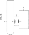
- the power transmission resonance coil 12 and the power reception resonance coil 21 both have protruding structures, however, it is also possible to employ a structure in which these are built into the underwater base station 1 and the autonomous underwater vehicle 2 respectively, and an aperture portion is provided in each one that emits electromagnetic waves to the outside and is covered by the power transmission balloon 13 and the power reception balloon 27 respectively.
- the power reception balloon 27 when the power reception balloon 27 is being inflated, it is possible to utilize a 'jamming transition' phenomenon in order to cover the power transmission resonance coil 12 and fix it in position by means of the power reception balloon 27.
- the power reception balloon 27 is filled in advance with a powder or granulated material. After the power reception balloon 27 has been inflated such that it covers the power transmission resonance coil 12, then the gas inside the power reception balloon 27 is suctioned out. As a result of this, the interior of the balloon is fixed in place by the friction of the powder or granulated material, and it is possible to firmly fix the power transmission resonance coil 12 in position by means of the power reception balloon 27.
- the power transmission balloon 13 when the power transmission balloon 13 is being inflated, it is possible to use the 'jamming transition' phenomenon in order to cover the power supply resonance coil 21 and fix it in position by means of the power transmission balloon 13.
- the power reception balloon 13 is filled in advance with a powder or granulated material. After the power reception balloon 13 has been inflated such that it covers the power transmission resonance coil 21, the gas inside the power reception balloon 13 is suctioned out. As a result of this, the interior of the balloon is fixed in place by the friction of the powder or granulated material, and it is possible to firmly fix the power reception resonance coil 21 in place by means of the power transmission balloon 13.
- the powder or granulated material may be formed from a material having a high level of magnetic permeability, or from a ceramic material that does not obstruct the wireless supply of power (for example, alumina, mullite, ferrite, forsterite, zirconia, zircon, cordierite, aluminum nitride, silicon nitride, silicon carbide, lead zirconate titanate, and conjugated compounds of these), and compounds of these with resins containing a high polymer material.
- a ceramic material that does not obstruct the wireless supply of power for example, alumina, mullite, ferrite, forsterite, zirconia, zircon, cordierite, aluminum nitride, silicon nitride, silicon carbide, lead zirconate titanate, and conjugated compounds of these
- the power transmission resonance coil 12 and the power reception coil 21 are built into the underwater base station 1 and the autonomous underwater vehicle 2 respectively, and an aperture portion is provided in each one that emits electromagnetic waves to the outside and is covered by the power transmission balloon 13 and the power reception balloon 27 respectively, then it is possible to introduce the powder or granulated material at the same time as the gas or fluid is introduced into the interior of each balloon such that the balloon portions become intertwined with each other, and to then discharge only the gas or fluid at mutually offset times in each balloon.
- the power transmission system of the present invention it is possible to achieve underwater power transmissions at low cost between a power-transmitting device and a power-receiving device. Moreover, it is possible to prevent the magnetic field being disturbed by the effects of ions and the like contained in the water, and it is thereby possible to prevent the efficiency of the power transmission between the power-transmitting device and the power-receiving device from deteriorating.
- a ... Power transmission system 1 ... Underwater base station (Power-transmitting device), 12 ... Power transmission resonance coil, 13 ... Power transmission balloon, 14 ... Power transmission balloon control mechanism, 2 ... Autonomous underwater vehicle (Power-receiving device), 21 ... Power reception resonance coil, 24 ... Battery, 27 ... Power reception balloon, 28 ... Power reception balloon control mechanism, 3 ... Electrical power system
Landscapes
- Engineering & Computer Science (AREA)
- Mechanical Engineering (AREA)
- Power Engineering (AREA)
- Aviation & Aerospace Engineering (AREA)
- Health & Medical Sciences (AREA)
- Life Sciences & Earth Sciences (AREA)
- Chemical & Material Sciences (AREA)
- Computer Networks & Wireless Communication (AREA)
- Food Science & Technology (AREA)
- Medicinal Chemistry (AREA)
- Physics & Mathematics (AREA)
- Analytical Chemistry (AREA)
- Biochemistry (AREA)
- General Health & Medical Sciences (AREA)
- General Physics & Mathematics (AREA)
- Immunology (AREA)
- Pathology (AREA)
- Transportation (AREA)
- Charge And Discharge Circuits For Batteries Or The Like (AREA)
Claims (8)
- Dispositif de transfert d'énergie comprenant :une bobine de résonance qui met en oeuvre un transfert d'énergie sans fil sous l'eau au moyen de la résonance de champ magnétique, etun ballon qui héberge en son sein la bobine de résonance.
- Dispositif de transfert d'énergie selon la revendication 1, comprenant en outre un mécanisme de contrôle du ballon qui, durant un transfert d'énergie, amène le ballon à se gonfler, et à d'autres moments, amène le ballon à se dégonfler.
- Dispositif de transfert d'énergie selon la revendication 1 ou 2, dans lequel
le dispositif de transfert d'énergie est une station de base subaquatique qui est installée sous l'eau à un emplacement prédéterminé et est raccordé grâce à un câble à un système d'énergie électrique terrestre, et qui reçoit de la part du système d'énergie électrique une alimentation en énergie qui doit être transférée. - Dispositif de transfert d'énergie selon la revendication 3, dans lequel
la station de base subaquatique est connectée par câble à un dispositif terrestre de contrôle des données de qualité d'eau et transmet les données de qualité d'eau qu'il reçoit d'une antenne par câble au dispositif de contrôle de données de qualité d'eau. - Dispositif de réception d'énergie comprenant :une bobine de résonance qui reçoit de l'énergie sans fil sous l'eau au moyen de la résonance de champ magnétique, etun ballon qui héberge en son sein la bobine de résonance.
- Dispositif de réception d'énergie selon la revendication 5, comprenant en outre un mécanisme de commande de ballon qui, durant la réception d'énergie, amène le ballon à se gonfler, et à d'autres moments, amène le ballon à se dégonfler.
- Dispositif de réception d'énergie selon la revendication 5 ou 6, dans lequel
le dispositif de réception d'énergie est un véhicule subaquatique autonome qui collecte des données de qualité d'eau alors qu'il se déplace dans l'eau grâce à l'énergie d'une batterie. - Dispositif de réception d'énergie selon la revendication 7, dans lequel
le véhicule subaquatique autonome transmet les données de qualité d'eau par l'intermédiaire d'une antenne durant un transfert d'énergie.
Applications Claiming Priority (2)
| Application Number | Priority Date | Filing Date | Title |
|---|---|---|---|
| JP2011268250 | 2011-12-07 | ||
| EP12856483.8A EP2790294B1 (fr) | 2011-12-07 | 2012-12-07 | Système de transmission de courant |
Related Parent Applications (2)
| Application Number | Title | Priority Date | Filing Date |
|---|---|---|---|
| EP12856483.8A Division EP2790294B1 (fr) | 2011-12-07 | 2012-12-07 | Système de transmission de courant |
| EP12856483.8A Division-Into EP2790294B1 (fr) | 2011-12-07 | 2012-12-07 | Système de transmission de courant |
Publications (2)
| Publication Number | Publication Date |
|---|---|
| EP3076517A1 EP3076517A1 (fr) | 2016-10-05 |
| EP3076517B1 true EP3076517B1 (fr) | 2017-07-26 |
Family
ID=48574383
Family Applications (2)
| Application Number | Title | Priority Date | Filing Date |
|---|---|---|---|
| EP16158312.5A Active EP3076517B1 (fr) | 2011-12-07 | 2012-12-07 | Système de transmission de puissance |
| EP12856483.8A Active EP2790294B1 (fr) | 2011-12-07 | 2012-12-07 | Système de transmission de courant |
Family Applications After (1)
| Application Number | Title | Priority Date | Filing Date |
|---|---|---|---|
| EP12856483.8A Active EP2790294B1 (fr) | 2011-12-07 | 2012-12-07 | Système de transmission de courant |
Country Status (5)
| Country | Link |
|---|---|
| US (1) | US9577462B2 (fr) |
| EP (2) | EP3076517B1 (fr) |
| JP (2) | JP5637319B2 (fr) |
| CN (2) | CN103959603B (fr) |
| WO (1) | WO2013085030A1 (fr) |
Families Citing this family (51)
| Publication number | Priority date | Publication date | Assignee | Title |
|---|---|---|---|---|
| US9327608B2 (en) * | 2011-08-04 | 2016-05-03 | Schneider Electric USA, Inc. | Extendable and deformable carrier for a primary coil of a charging system |
| CN104081482B (zh) * | 2012-02-06 | 2017-04-12 | 株式会社 Ihi | 非接触式供电系统 |
| JP6111583B2 (ja) * | 2012-10-01 | 2017-04-12 | 株式会社Ihi | 非接触給電システム |
| US9893557B2 (en) | 2013-07-12 | 2018-02-13 | Schneider Electric USA, Inc. | Method and device for foreign object detection in induction electric charger |
| JP6376732B2 (ja) | 2013-07-18 | 2018-08-22 | Ihi運搬機械株式会社 | 非接触給電システム |
| GB2521626C (en) | 2013-12-23 | 2019-10-30 | Subsea 7 Ltd | Transmission of power underwater |
| EP3101778B1 (fr) | 2014-01-29 | 2020-02-19 | Nec Corporation | Dispositif de commande de transmission de puissance sans fil, système de transmission de puissance sans fil et procédé de commande de transmission de puissance sans fil |
| WO2015129247A1 (fr) * | 2014-02-25 | 2015-09-03 | 日本電気株式会社 | Dispositif, système et procédé d'alimentation électrique sans fil |
| EP3457524B1 (fr) | 2014-06-06 | 2020-03-25 | IHI Corporation | Dispositif de transmission de puissance, dispositif de réception d'énergie et système d'alimentation électrique sans fil |
| FR3022411B1 (fr) * | 2014-06-13 | 2016-07-15 | Dcns | Engin sous marin comportant des sources de stockage d'energie a base de batteries lithium-ion |
| WO2016153589A2 (fr) * | 2015-01-23 | 2016-09-29 | Battelle Memorial Institute | Système sous-marin de transfert d'énergie et de données |
| WO2016121089A1 (fr) * | 2015-01-30 | 2016-08-04 | 中国電力株式会社 | Système et procédé d'alimentation électrique |
| US9829599B2 (en) | 2015-03-23 | 2017-11-28 | Schneider Electric USA, Inc. | Sensor and method for foreign object detection in induction electric charger |
| JP6531942B2 (ja) | 2015-07-21 | 2019-06-19 | パナソニックIpマネジメント株式会社 | 送電装置 |
| JP6581874B2 (ja) * | 2015-10-06 | 2019-09-25 | 川崎重工業株式会社 | 自律型無人潜水機の充電システム |
| CN105826983A (zh) * | 2016-05-12 | 2016-08-03 | 大连理工大学 | 一种用于水下装置的供电系统 |
| JP6737648B2 (ja) * | 2016-06-30 | 2020-08-12 | パナソニック株式会社 | 送電装置 |
| US10392086B2 (en) | 2016-08-26 | 2019-08-27 | Saudi Arabian Oil Company | Wirelessly controlled subsystems for underwater remotely operated vehicles |
| JP6848320B2 (ja) * | 2016-10-06 | 2021-03-24 | 富士ゼロックス株式会社 | 水中移動体 |
| JP6927688B2 (ja) | 2016-10-28 | 2021-09-01 | パナソニック株式会社 | 送電システム |
| WO2018158874A1 (fr) * | 2017-03-01 | 2018-09-07 | 中国電力株式会社 | Système d'alimentation électrique sans contact, installation de transmission d'énergie et installation de réception d'énergie |
| FR3064246B1 (fr) * | 2017-03-23 | 2023-11-10 | Dcns | Systeme immerge de stockage et de maintien en condition operationnelle d'un engin sous-marin comme un drone |
| US11305663B2 (en) * | 2017-03-27 | 2022-04-19 | General Electric Company | Energy efficient hands-free electric vehicle charger for autonomous vehicles in uncontrolled environments |
| JP6568133B2 (ja) | 2017-03-30 | 2019-08-28 | パナソニック株式会社 | 伝送コイル及び送電装置 |
| JP6594373B2 (ja) * | 2017-05-10 | 2019-10-23 | パナソニック株式会社 | 送電装置 |
| US10807692B2 (en) | 2017-05-26 | 2020-10-20 | Lynntech, Inc. | Undersea vehicle and method for operating the same |
| US10543893B2 (en) * | 2017-05-26 | 2020-01-28 | Lynntech, Inc. | Undersea vehicle and method for operating a reactor |
| US10916785B2 (en) | 2017-05-26 | 2021-02-09 | Lynntech, Inc. | Fuel cell storage system |
| US10622845B2 (en) | 2017-12-05 | 2020-04-14 | Searete Llc | Non-Gaussian beamforming for wireless power transfer optimization |
| CN107769345A (zh) * | 2017-12-08 | 2018-03-06 | 武汉理工大学 | 一种电动游艇无线充电装置 |
| JP6588684B1 (ja) | 2018-03-27 | 2019-10-09 | パナソニック株式会社 | 送電装置 |
| JP7069939B2 (ja) * | 2018-03-28 | 2022-05-18 | 日本電気株式会社 | 移動体、充電システム、制御方法及びプログラム |
| JP7148266B2 (ja) * | 2018-04-26 | 2022-10-05 | 川崎重工業株式会社 | 自律型無人潜水機を用いた作業方法 |
| CN108820171A (zh) * | 2018-05-23 | 2018-11-16 | 山东交通学院 | 一种采用可再生能源的水下组网持续观测系统及其方法 |
| JP7117540B2 (ja) | 2018-07-31 | 2022-08-15 | パナソニックIpマネジメント株式会社 | 受電装置および水中給電システム |
| KR102097682B1 (ko) * | 2018-10-16 | 2020-04-06 | 국방과학연구소 | 수중 전원 시스템 및 그 운용 방법 |
| CN118205412A (zh) * | 2018-10-17 | 2024-06-18 | 合芯磁导科技(无锡)有限公司 | 电动汽车无线充电发射器用伸缩式安全防护栏 |
| US11926232B2 (en) | 2018-12-19 | 2024-03-12 | Wpc Wireless Power And Communication As | System for docking a submarine vessel to a docking port and a method for docking the submarine vessel on the docking port |
| JP7263954B2 (ja) * | 2019-07-12 | 2023-04-25 | 株式会社Ihi | 給電システム |
| JP7302381B2 (ja) * | 2019-08-26 | 2023-07-04 | 株式会社Ihi | コイル装置 |
| NL2024690B1 (en) * | 2020-01-17 | 2021-09-08 | Fnv Ip Bv | Underwater vehicle docking and communication |
| JP7582851B2 (ja) | 2020-11-30 | 2024-11-13 | パナソニックホールディングス株式会社 | 受電装置、送電電圧制御方法および水中給電システム |
| CN112477643B (zh) * | 2020-12-10 | 2022-08-19 | 重庆凝光科技有限公司 | 一种水下充电装置 |
| US12459378B2 (en) * | 2020-12-21 | 2025-11-04 | Ihi Corporation | Coil device, and contactless power supply system |
| WO2022149001A1 (fr) * | 2021-01-11 | 2022-07-14 | Podhola Kamil | Système de transfert d'énergie sans fil en haute mer |
| CN112758286A (zh) * | 2021-01-20 | 2021-05-07 | 威泊(上海)新能源科技股份有限公司 | 一种集群作业的无线充电水下常驻智能机器人系统及方法 |
| US20230064567A1 (en) * | 2021-09-01 | 2023-03-02 | X Development Llc | Autonomous seagoing power replenishment watercraft |
| US12189353B2 (en) | 2021-11-19 | 2025-01-07 | Tidalx Ai Inc. | Watercraft servicing system |
| KR102694125B1 (ko) * | 2021-12-30 | 2024-08-09 | 대진대학교 산학협력단 | 잠수정 수중 무선충전 시스템 |
| NO349316B1 (en) * | 2022-08-29 | 2025-12-01 | Blue Logic As | Apparatus for wireless transmission of power and data in high-pressure environments |
| CN119298412B (zh) * | 2024-09-27 | 2025-09-19 | 西北工业大学 | 一种水下装备回收无线充电机械臂装置 |
Family Cites Families (18)
| Publication number | Priority date | Publication date | Assignee | Title |
|---|---|---|---|---|
| JPS62122435A (ja) | 1985-11-22 | 1987-06-03 | Oki Electric Ind Co Ltd | ネツトワ−クのアクセス方式 |
| JPS62122435U (fr) * | 1986-01-23 | 1987-08-04 | ||
| JPH0799910B2 (ja) * | 1988-07-20 | 1995-10-25 | 三井造船株式会社 | 遠隔水中電力供給装置 |
| JP3493426B2 (ja) | 2000-01-17 | 2004-02-03 | 独立行政法人通信総合研究所 | バルーン型アンテナ |
| CN101266287A (zh) * | 2002-05-16 | 2008-09-17 | 梅德拉股份有限公司 | 应用3.0泰斯拉磁共振系统获取内腔结构图像与谱图的系统与方法 |
| JP2004166459A (ja) * | 2002-11-15 | 2004-06-10 | Mitsui Eng & Shipbuild Co Ltd | 非接触給電装置 |
| DE102005000761B4 (de) * | 2005-01-04 | 2008-05-21 | Siemens Ag | Intrakorporal zu setzende Endolokalspule zur Aufnahme von Magnetresonanzsignalen |
| CN2887748Y (zh) * | 2006-04-29 | 2007-04-11 | 中国科学院沈阳自动化研究所 | 水下监测平台用水下机器人 |
| CN101197507A (zh) * | 2006-12-06 | 2008-06-11 | 北京中电华大电子设计有限责任公司 | 无线电源装置及电路 |
| US8212414B2 (en) * | 2008-07-10 | 2012-07-03 | Lockheed Martin Corporation | Resonant, contactless radio frequency power coupling |
| US8304935B2 (en) * | 2008-09-27 | 2012-11-06 | Witricity Corporation | Wireless energy transfer using field shaping to reduce loss |
| US8324759B2 (en) * | 2008-09-27 | 2012-12-04 | Witricity Corporation | Wireless energy transfer using magnetic materials to shape field and reduce loss |
| JP4478729B1 (ja) * | 2008-12-24 | 2010-06-09 | 株式会社豊田自動織機 | 共鳴型非接触充電装置 |
| JP5016069B2 (ja) * | 2010-01-12 | 2012-09-05 | トヨタ自動車株式会社 | 電力伝送システムおよび車両用給電装置 |
| JP2011234605A (ja) * | 2010-04-05 | 2011-11-17 | Tdk Corp | ワイヤレス受電装置およびワイヤレス電力伝送システム |
| US8968609B2 (en) * | 2010-05-12 | 2015-03-03 | General Electric Company | Dielectric materials for power transfer system |
| CN201928065U (zh) * | 2011-01-04 | 2011-08-10 | 深圳市航嘉驰源电气股份有限公司 | 无线充电器 |
| EP2678958B1 (fr) * | 2011-02-21 | 2020-04-15 | Wisub AS | Dispositif de connecteur subaquatique |
-
2012
- 2012-12-07 WO PCT/JP2012/081781 patent/WO2013085030A1/fr not_active Ceased
- 2012-12-07 CN CN201280059930.3A patent/CN103959603B/zh active Active
- 2012-12-07 EP EP16158312.5A patent/EP3076517B1/fr active Active
- 2012-12-07 CN CN201610359374.1A patent/CN105966578B/zh active Active
- 2012-12-07 EP EP12856483.8A patent/EP2790294B1/fr active Active
- 2012-12-07 JP JP2013548313A patent/JP5637319B2/ja active Active
-
2014
- 2014-05-01 US US14/266,911 patent/US9577462B2/en active Active
- 2014-10-23 JP JP2014216455A patent/JP5807712B2/ja active Active
Also Published As
| Publication number | Publication date |
|---|---|
| US20140232200A1 (en) | 2014-08-21 |
| CN105966578B (zh) | 2018-04-06 |
| JP2015015901A (ja) | 2015-01-22 |
| JPWO2013085030A1 (ja) | 2015-04-27 |
| EP2790294A1 (fr) | 2014-10-15 |
| JP5807712B2 (ja) | 2015-11-10 |
| CN105966578A (zh) | 2016-09-28 |
| CN103959603B (zh) | 2016-07-06 |
| JP5637319B2 (ja) | 2014-12-10 |
| EP2790294A4 (fr) | 2015-08-19 |
| EP3076517A1 (fr) | 2016-10-05 |
| EP2790294B1 (fr) | 2016-05-11 |
| CN103959603A (zh) | 2014-07-30 |
| US9577462B2 (en) | 2017-02-21 |
| WO2013085030A1 (fr) | 2013-06-13 |
Similar Documents
| Publication | Publication Date | Title |
|---|---|---|
| EP3076517B1 (fr) | Système de transmission de puissance | |
| EP2953238B1 (fr) | Système d'alimentation électrique sans contact | |
| CN105191064B (zh) | 非接触供电系统 | |
| US11502550B2 (en) | Power transmitting device that transmits power to power receiving device having power receiving coil in water | |
| US9362783B2 (en) | Wireless power transmission apparatus using ultrasound | |
| WO2016153589A2 (fr) | Système sous-marin de transfert d'énergie et de données | |
| CN104081482B (zh) | 非接触式供电系统 | |
| CN104904096B (zh) | 非接触供电系统 | |
| JP6622157B2 (ja) | 水中非接触給電装置 | |
| KR20240122723A (ko) | 잠수정 수중 무선충전 시스템 | |
| JP2021114833A (ja) | 水中非接触給電装置 | |
| WO2016121089A1 (fr) | Système et procédé d'alimentation électrique | |
| EP3018668B1 (fr) | Propulseur azimutal avec appareil permettant le transfert d'énergie électrique | |
| KR102437144B1 (ko) | 전기 에너지 전달 장치 | |
| JP6146124B2 (ja) | 非接触給電システム及びシステム | |
| JP2018078773A (ja) | 無線給電装置、及び無線給電方法 | |
| JP6760806B2 (ja) | 無線給電装置 | |
| JP6146116B2 (ja) | 非接触給電システム及び袋体システム | |
| US20240421634A1 (en) | Rotatable transmitter paddle and paddle receiver housing for wireless power transfer | |
| Medeiros | Inductive Coupling Method for Remote Powering of Sensors |
Legal Events
| Date | Code | Title | Description |
|---|---|---|---|
| PUAI | Public reference made under article 153(3) epc to a published international application that has entered the european phase |
Free format text: ORIGINAL CODE: 0009012 |
|
| 17P | Request for examination filed |
Effective date: 20160302 |
|
| AC | Divisional application: reference to earlier application |
Ref document number: 2790294 Country of ref document: EP Kind code of ref document: P |
|
| AK | Designated contracting states |
Kind code of ref document: A1 Designated state(s): AL AT BE BG CH CY CZ DE DK EE ES FI FR GB GR HR HU IE IS IT LI LT LU LV MC MK MT NL NO PL PT RO RS SE SI SK SM TR |
|
| GRAP | Despatch of communication of intention to grant a patent |
Free format text: ORIGINAL CODE: EPIDOSNIGR1 |
|
| RIC1 | Information provided on ipc code assigned before grant |
Ipc: H02J 7/00 20060101AFI20170112BHEP |
|
| INTG | Intention to grant announced |
Effective date: 20170210 |
|
| GRAS | Grant fee paid |
Free format text: ORIGINAL CODE: EPIDOSNIGR3 |
|
| GRAA | (expected) grant |
Free format text: ORIGINAL CODE: 0009210 |
|
| AC | Divisional application: reference to earlier application |
Ref document number: 2790294 Country of ref document: EP Kind code of ref document: P |
|
| AK | Designated contracting states |
Kind code of ref document: B1 Designated state(s): AL AT BE BG CH CY CZ DE DK EE ES FI FR GB GR HR HU IE IS IT LI LT LU LV MC MK MT NL NO PL PT RO RS SE SI SK SM TR |
|
| REG | Reference to a national code |
Ref country code: GB Ref legal event code: FG4D |
|
| REG | Reference to a national code |
Ref country code: CH Ref legal event code: EP |
|
| REG | Reference to a national code |
Ref country code: AT Ref legal event code: REF Ref document number: 913143 Country of ref document: AT Kind code of ref document: T Effective date: 20170815 |
|
| REG | Reference to a national code |
Ref country code: IE Ref legal event code: FG4D |
|
| REG | Reference to a national code |
Ref country code: DE Ref legal event code: R096 Ref document number: 602012035195 Country of ref document: DE |
|
| REG | Reference to a national code |
Ref country code: NL Ref legal event code: MP Effective date: 20170726 |
|
| REG | Reference to a national code |
Ref country code: LT Ref legal event code: MG4D |
|
| REG | Reference to a national code |
Ref country code: AT Ref legal event code: MK05 Ref document number: 913143 Country of ref document: AT Kind code of ref document: T Effective date: 20170726 |
|
| PG25 | Lapsed in a contracting state [announced via postgrant information from national office to epo] |
Ref country code: NO Free format text: LAPSE BECAUSE OF FAILURE TO SUBMIT A TRANSLATION OF THE DESCRIPTION OR TO PAY THE FEE WITHIN THE PRESCRIBED TIME-LIMIT Effective date: 20171026 Ref country code: LT Free format text: LAPSE BECAUSE OF FAILURE TO SUBMIT A TRANSLATION OF THE DESCRIPTION OR TO PAY THE FEE WITHIN THE PRESCRIBED TIME-LIMIT Effective date: 20170726 Ref country code: AT Free format text: LAPSE BECAUSE OF FAILURE TO SUBMIT A TRANSLATION OF THE DESCRIPTION OR TO PAY THE FEE WITHIN THE PRESCRIBED TIME-LIMIT Effective date: 20170726 Ref country code: HR Free format text: LAPSE BECAUSE OF FAILURE TO SUBMIT A TRANSLATION OF THE DESCRIPTION OR TO PAY THE FEE WITHIN THE PRESCRIBED TIME-LIMIT Effective date: 20170726 Ref country code: NL Free format text: LAPSE BECAUSE OF FAILURE TO SUBMIT A TRANSLATION OF THE DESCRIPTION OR TO PAY THE FEE WITHIN THE PRESCRIBED TIME-LIMIT Effective date: 20170726 Ref country code: SE Free format text: LAPSE BECAUSE OF FAILURE TO SUBMIT A TRANSLATION OF THE DESCRIPTION OR TO PAY THE FEE WITHIN THE PRESCRIBED TIME-LIMIT Effective date: 20170726 Ref country code: FI Free format text: LAPSE BECAUSE OF FAILURE TO SUBMIT A TRANSLATION OF THE DESCRIPTION OR TO PAY THE FEE WITHIN THE PRESCRIBED TIME-LIMIT Effective date: 20170726 |
|
| PG25 | Lapsed in a contracting state [announced via postgrant information from national office to epo] |
Ref country code: PL Free format text: LAPSE BECAUSE OF FAILURE TO SUBMIT A TRANSLATION OF THE DESCRIPTION OR TO PAY THE FEE WITHIN THE PRESCRIBED TIME-LIMIT Effective date: 20170726 Ref country code: LV Free format text: LAPSE BECAUSE OF FAILURE TO SUBMIT A TRANSLATION OF THE DESCRIPTION OR TO PAY THE FEE WITHIN THE PRESCRIBED TIME-LIMIT Effective date: 20170726 Ref country code: ES Free format text: LAPSE BECAUSE OF FAILURE TO SUBMIT A TRANSLATION OF THE DESCRIPTION OR TO PAY THE FEE WITHIN THE PRESCRIBED TIME-LIMIT Effective date: 20170726 Ref country code: RS Free format text: LAPSE BECAUSE OF FAILURE TO SUBMIT A TRANSLATION OF THE DESCRIPTION OR TO PAY THE FEE WITHIN THE PRESCRIBED TIME-LIMIT Effective date: 20170726 Ref country code: GR Free format text: LAPSE BECAUSE OF FAILURE TO SUBMIT A TRANSLATION OF THE DESCRIPTION OR TO PAY THE FEE WITHIN THE PRESCRIBED TIME-LIMIT Effective date: 20171027 Ref country code: BG Free format text: LAPSE BECAUSE OF FAILURE TO SUBMIT A TRANSLATION OF THE DESCRIPTION OR TO PAY THE FEE WITHIN THE PRESCRIBED TIME-LIMIT Effective date: 20171026 Ref country code: IS Free format text: LAPSE BECAUSE OF FAILURE TO SUBMIT A TRANSLATION OF THE DESCRIPTION OR TO PAY THE FEE WITHIN THE PRESCRIBED TIME-LIMIT Effective date: 20171126 |
|
| PG25 | Lapsed in a contracting state [announced via postgrant information from national office to epo] |
Ref country code: RO Free format text: LAPSE BECAUSE OF FAILURE TO SUBMIT A TRANSLATION OF THE DESCRIPTION OR TO PAY THE FEE WITHIN THE PRESCRIBED TIME-LIMIT Effective date: 20170726 Ref country code: DK Free format text: LAPSE BECAUSE OF FAILURE TO SUBMIT A TRANSLATION OF THE DESCRIPTION OR TO PAY THE FEE WITHIN THE PRESCRIBED TIME-LIMIT Effective date: 20170726 Ref country code: CZ Free format text: LAPSE BECAUSE OF FAILURE TO SUBMIT A TRANSLATION OF THE DESCRIPTION OR TO PAY THE FEE WITHIN THE PRESCRIBED TIME-LIMIT Effective date: 20170726 |
|
| REG | Reference to a national code |
Ref country code: DE Ref legal event code: R097 Ref document number: 602012035195 Country of ref document: DE |
|
| PG25 | Lapsed in a contracting state [announced via postgrant information from national office to epo] |
Ref country code: IT Free format text: LAPSE BECAUSE OF FAILURE TO SUBMIT A TRANSLATION OF THE DESCRIPTION OR TO PAY THE FEE WITHIN THE PRESCRIBED TIME-LIMIT Effective date: 20170726 Ref country code: SK Free format text: LAPSE BECAUSE OF FAILURE TO SUBMIT A TRANSLATION OF THE DESCRIPTION OR TO PAY THE FEE WITHIN THE PRESCRIBED TIME-LIMIT Effective date: 20170726 Ref country code: EE Free format text: LAPSE BECAUSE OF FAILURE TO SUBMIT A TRANSLATION OF THE DESCRIPTION OR TO PAY THE FEE WITHIN THE PRESCRIBED TIME-LIMIT Effective date: 20170726 Ref country code: SM Free format text: LAPSE BECAUSE OF FAILURE TO SUBMIT A TRANSLATION OF THE DESCRIPTION OR TO PAY THE FEE WITHIN THE PRESCRIBED TIME-LIMIT Effective date: 20170726 |
|
| PLBE | No opposition filed within time limit |
Free format text: ORIGINAL CODE: 0009261 |
|
| STAA | Information on the status of an ep patent application or granted ep patent |
Free format text: STATUS: NO OPPOSITION FILED WITHIN TIME LIMIT |
|
| REG | Reference to a national code |
Ref country code: DE Ref legal event code: R119 Ref document number: 602012035195 Country of ref document: DE |
|
| 26N | No opposition filed |
Effective date: 20180430 |
|
| REG | Reference to a national code |
Ref country code: CH Ref legal event code: PL |
|
| PG25 | Lapsed in a contracting state [announced via postgrant information from national office to epo] |
Ref country code: SI Free format text: LAPSE BECAUSE OF FAILURE TO SUBMIT A TRANSLATION OF THE DESCRIPTION OR TO PAY THE FEE WITHIN THE PRESCRIBED TIME-LIMIT Effective date: 20170726 |
|
| REG | Reference to a national code |
Ref country code: IE Ref legal event code: MM4A |
|
| PG25 | Lapsed in a contracting state [announced via postgrant information from national office to epo] |
Ref country code: LU Free format text: LAPSE BECAUSE OF NON-PAYMENT OF DUE FEES Effective date: 20171207 Ref country code: MT Free format text: LAPSE BECAUSE OF NON-PAYMENT OF DUE FEES Effective date: 20171207 |
|
| REG | Reference to a national code |
Ref country code: FR Ref legal event code: ST Effective date: 20180831 |
|
| REG | Reference to a national code |
Ref country code: BE Ref legal event code: MM Effective date: 20171231 |
|
| PG25 | Lapsed in a contracting state [announced via postgrant information from national office to epo] |
Ref country code: IE Free format text: LAPSE BECAUSE OF NON-PAYMENT OF DUE FEES Effective date: 20171207 Ref country code: FR Free format text: LAPSE BECAUSE OF NON-PAYMENT OF DUE FEES Effective date: 20180102 Ref country code: DE Free format text: LAPSE BECAUSE OF NON-PAYMENT OF DUE FEES Effective date: 20180703 |
|
| PG25 | Lapsed in a contracting state [announced via postgrant information from national office to epo] |
Ref country code: BE Free format text: LAPSE BECAUSE OF NON-PAYMENT OF DUE FEES Effective date: 20171231 Ref country code: CH Free format text: LAPSE BECAUSE OF NON-PAYMENT OF DUE FEES Effective date: 20171231 Ref country code: LI Free format text: LAPSE BECAUSE OF NON-PAYMENT OF DUE FEES Effective date: 20171231 |
|
| PG25 | Lapsed in a contracting state [announced via postgrant information from national office to epo] |
Ref country code: HU Free format text: LAPSE BECAUSE OF FAILURE TO SUBMIT A TRANSLATION OF THE DESCRIPTION OR TO PAY THE FEE WITHIN THE PRESCRIBED TIME-LIMIT; INVALID AB INITIO Effective date: 20121207 Ref country code: MC Free format text: LAPSE BECAUSE OF FAILURE TO SUBMIT A TRANSLATION OF THE DESCRIPTION OR TO PAY THE FEE WITHIN THE PRESCRIBED TIME-LIMIT Effective date: 20170726 |
|
| PG25 | Lapsed in a contracting state [announced via postgrant information from national office to epo] |
Ref country code: CY Free format text: LAPSE BECAUSE OF FAILURE TO SUBMIT A TRANSLATION OF THE DESCRIPTION OR TO PAY THE FEE WITHIN THE PRESCRIBED TIME-LIMIT Effective date: 20170726 |
|
| PG25 | Lapsed in a contracting state [announced via postgrant information from national office to epo] |
Ref country code: MK Free format text: LAPSE BECAUSE OF FAILURE TO SUBMIT A TRANSLATION OF THE DESCRIPTION OR TO PAY THE FEE WITHIN THE PRESCRIBED TIME-LIMIT Effective date: 20170726 |
|
| PG25 | Lapsed in a contracting state [announced via postgrant information from national office to epo] |
Ref country code: TR Free format text: LAPSE BECAUSE OF FAILURE TO SUBMIT A TRANSLATION OF THE DESCRIPTION OR TO PAY THE FEE WITHIN THE PRESCRIBED TIME-LIMIT Effective date: 20170726 |
|
| PG25 | Lapsed in a contracting state [announced via postgrant information from national office to epo] |
Ref country code: PT Free format text: LAPSE BECAUSE OF FAILURE TO SUBMIT A TRANSLATION OF THE DESCRIPTION OR TO PAY THE FEE WITHIN THE PRESCRIBED TIME-LIMIT Effective date: 20170726 |
|
| PG25 | Lapsed in a contracting state [announced via postgrant information from national office to epo] |
Ref country code: AL Free format text: LAPSE BECAUSE OF FAILURE TO SUBMIT A TRANSLATION OF THE DESCRIPTION OR TO PAY THE FEE WITHIN THE PRESCRIBED TIME-LIMIT Effective date: 20170726 |
|
| PGFP | Annual fee paid to national office [announced via postgrant information from national office to epo] |
Ref country code: GB Payment date: 20251030 Year of fee payment: 14 |