EP3076529A1 - Machine électrique tournante dotée d'aimants lenticulaires magnétisés latéralement - Google Patents
Machine électrique tournante dotée d'aimants lenticulaires magnétisés latéralement Download PDFInfo
- Publication number
- EP3076529A1 EP3076529A1 EP15162240.4A EP15162240A EP3076529A1 EP 3076529 A1 EP3076529 A1 EP 3076529A1 EP 15162240 A EP15162240 A EP 15162240A EP 3076529 A1 EP3076529 A1 EP 3076529A1
- Authority
- EP
- European Patent Office
- Prior art keywords
- stator
- inner stator
- permanent magnets
- rotary machine
- electric rotary
- Prior art date
- Legal status (The legal status is an assumption and is not a legal conclusion. Google has not performed a legal analysis and makes no representation as to the accuracy of the status listed.)
- Withdrawn
Links
- 238000001816 cooling Methods 0.000 claims description 46
- 230000005291 magnetic effect Effects 0.000 claims description 31
- 238000004804 winding Methods 0.000 claims description 12
- 229910052782 aluminium Inorganic materials 0.000 claims description 8
- XAGFODPZIPBFFR-UHFFFAOYSA-N aluminium Chemical compound [Al] XAGFODPZIPBFFR-UHFFFAOYSA-N 0.000 claims description 8
- 229910000859 α-Fe Inorganic materials 0.000 claims description 7
- 239000000696 magnetic material Substances 0.000 claims description 6
- QJVKUMXDEUEQLH-UHFFFAOYSA-N [B].[Fe].[Nd] Chemical compound [B].[Fe].[Nd] QJVKUMXDEUEQLH-UHFFFAOYSA-N 0.000 claims description 5
- 239000000110 cooling liquid Substances 0.000 claims description 4
- 229910052751 metal Inorganic materials 0.000 claims description 4
- 239000002184 metal Substances 0.000 claims description 4
- XEEYBQQBJWHFJM-UHFFFAOYSA-N Iron Chemical compound [Fe] XEEYBQQBJWHFJM-UHFFFAOYSA-N 0.000 description 25
- 229910052742 iron Inorganic materials 0.000 description 11
- 239000000463 material Substances 0.000 description 9
- 230000001360 synchronised effect Effects 0.000 description 6
- 239000002826 coolant Substances 0.000 description 4
- 229910001172 neodymium magnet Inorganic materials 0.000 description 4
- 230000004323 axial length Effects 0.000 description 3
- 230000015572 biosynthetic process Effects 0.000 description 3
- 230000005415 magnetization Effects 0.000 description 3
- 238000004519 manufacturing process Methods 0.000 description 3
- ZOXJGFHDIHLPTG-UHFFFAOYSA-N Boron Chemical compound [B] ZOXJGFHDIHLPTG-UHFFFAOYSA-N 0.000 description 2
- 230000006698 induction Effects 0.000 description 2
- 229910052761 rare earth metal Inorganic materials 0.000 description 2
- 150000002910 rare earth metals Chemical class 0.000 description 2
- 229910000521 B alloy Inorganic materials 0.000 description 1
- RYGMFSIKBFXOCR-UHFFFAOYSA-N Copper Chemical compound [Cu] RYGMFSIKBFXOCR-UHFFFAOYSA-N 0.000 description 1
- 229910000640 Fe alloy Inorganic materials 0.000 description 1
- 229910000583 Nd alloy Inorganic materials 0.000 description 1
- 229910052779 Neodymium Inorganic materials 0.000 description 1
- 229910052788 barium Inorganic materials 0.000 description 1
- DSAJWYNOEDNPEQ-UHFFFAOYSA-N barium atom Chemical compound [Ba] DSAJWYNOEDNPEQ-UHFFFAOYSA-N 0.000 description 1
- 230000005540 biological transmission Effects 0.000 description 1
- 229910052796 boron Inorganic materials 0.000 description 1
- 229910010293 ceramic material Inorganic materials 0.000 description 1
- 229910017052 cobalt Inorganic materials 0.000 description 1
- 239000010941 cobalt Substances 0.000 description 1
- GUTLYIVDDKVIGB-UHFFFAOYSA-N cobalt atom Chemical compound [Co] GUTLYIVDDKVIGB-UHFFFAOYSA-N 0.000 description 1
- 238000002485 combustion reaction Methods 0.000 description 1
- 229910052802 copper Inorganic materials 0.000 description 1
- 239000010949 copper Substances 0.000 description 1
- 230000005293 ferrimagnetic effect Effects 0.000 description 1
- -1 for example Substances 0.000 description 1
- 239000000203 mixture Substances 0.000 description 1
- QEFYFXOXNSNQGX-UHFFFAOYSA-N neodymium atom Chemical compound [Nd] QEFYFXOXNSNQGX-UHFFFAOYSA-N 0.000 description 1
- 238000005457 optimization Methods 0.000 description 1
- 238000013021 overheating Methods 0.000 description 1
- 238000007493 shaping process Methods 0.000 description 1
- 229910052712 strontium Inorganic materials 0.000 description 1
- CIOAGBVUUVVLOB-UHFFFAOYSA-N strontium atom Chemical compound [Sr] CIOAGBVUUVVLOB-UHFFFAOYSA-N 0.000 description 1
- XLYOFNOQVPJJNP-UHFFFAOYSA-N water Substances O XLYOFNOQVPJJNP-UHFFFAOYSA-N 0.000 description 1
Images


Classifications
-
- H—ELECTRICITY
- H02—GENERATION; CONVERSION OR DISTRIBUTION OF ELECTRIC POWER
- H02K—DYNAMO-ELECTRIC MACHINES
- H02K1/00—Details of the magnetic circuit
- H02K1/06—Details of the magnetic circuit characterised by the shape, form or construction
- H02K1/12—Stationary parts of the magnetic circuit
- H02K1/17—Stator cores with permanent magnets
-
- H—ELECTRICITY
- H02—GENERATION; CONVERSION OR DISTRIBUTION OF ELECTRIC POWER
- H02K—DYNAMO-ELECTRIC MACHINES
- H02K16/00—Machines with more than one rotor or stator
- H02K16/04—Machines with one rotor and two stators
-
- B—PERFORMING OPERATIONS; TRANSPORTING
- B60—VEHICLES IN GENERAL
- B60K—ARRANGEMENT OR MOUNTING OF PROPULSION UNITS OR OF TRANSMISSIONS IN VEHICLES; ARRANGEMENT OR MOUNTING OF PLURAL DIVERSE PRIME-MOVERS IN VEHICLES; AUXILIARY DRIVES FOR VEHICLES; INSTRUMENTATION OR DASHBOARDS FOR VEHICLES; ARRANGEMENTS IN CONNECTION WITH COOLING, AIR INTAKE, GAS EXHAUST OR FUEL SUPPLY OF PROPULSION UNITS IN VEHICLES
- B60K1/00—Arrangement or mounting of electrical propulsion units
-
- F—MECHANICAL ENGINEERING; LIGHTING; HEATING; WEAPONS; BLASTING
- F03—MACHINES OR ENGINES FOR LIQUIDS; WIND, SPRING, OR WEIGHT MOTORS; PRODUCING MECHANICAL POWER OR A REACTIVE PROPULSIVE THRUST, NOT OTHERWISE PROVIDED FOR
- F03D—WIND MOTORS
- F03D9/00—Adaptations of wind motors for special use; Combinations of wind motors with apparatus driven thereby; Wind motors specially adapted for installation in particular locations
- F03D9/20—Wind motors characterised by the driven apparatus
- F03D9/25—Wind motors characterised by the driven apparatus the apparatus being an electrical generator
-
- H—ELECTRICITY
- H02—GENERATION; CONVERSION OR DISTRIBUTION OF ELECTRIC POWER
- H02K—DYNAMO-ELECTRIC MACHINES
- H02K1/00—Details of the magnetic circuit
- H02K1/02—Details of the magnetic circuit characterised by the magnetic material
-
- H—ELECTRICITY
- H02—GENERATION; CONVERSION OR DISTRIBUTION OF ELECTRIC POWER
- H02K—DYNAMO-ELECTRIC MACHINES
- H02K1/00—Details of the magnetic circuit
- H02K1/06—Details of the magnetic circuit characterised by the shape, form or construction
- H02K1/12—Stationary parts of the magnetic circuit
- H02K1/20—Stationary parts of the magnetic circuit with channels or ducts for flow of cooling medium
-
- H—ELECTRICITY
- H02—GENERATION; CONVERSION OR DISTRIBUTION OF ELECTRIC POWER
- H02K—DYNAMO-ELECTRIC MACHINES
- H02K1/00—Details of the magnetic circuit
- H02K1/06—Details of the magnetic circuit characterised by the shape, form or construction
- H02K1/22—Rotating parts of the magnetic circuit
-
- H—ELECTRICITY
- H02—GENERATION; CONVERSION OR DISTRIBUTION OF ELECTRIC POWER
- H02K—DYNAMO-ELECTRIC MACHINES
- H02K21/00—Synchronous motors having permanent magnets; Synchronous generators having permanent magnets
- H02K21/38—Synchronous motors having permanent magnets; Synchronous generators having permanent magnets with rotating flux distributors, and armatures and magnets both stationary
- H02K21/40—Synchronous motors having permanent magnets; Synchronous generators having permanent magnets with rotating flux distributors, and armatures and magnets both stationary with flux distributors rotating around the magnets and within the armatures
-
- H—ELECTRICITY
- H02—GENERATION; CONVERSION OR DISTRIBUTION OF ELECTRIC POWER
- H02K—DYNAMO-ELECTRIC MACHINES
- H02K3/00—Details of windings
- H02K3/04—Windings characterised by the conductor shape, form or construction, e.g. with bar conductors
- H02K3/28—Layout of windings or of connections between windings
-
- H—ELECTRICITY
- H02—GENERATION; CONVERSION OR DISTRIBUTION OF ELECTRIC POWER
- H02K—DYNAMO-ELECTRIC MACHINES
- H02K5/00—Casings; Enclosures; Supports
- H02K5/04—Casings or enclosures characterised by the shape, form or construction thereof
- H02K5/20—Casings or enclosures characterised by the shape, form or construction thereof with channels or ducts for flow of cooling medium
- H02K5/203—Casings or enclosures characterised by the shape, form or construction thereof with channels or ducts for flow of cooling medium specially adapted for liquids, e.g. cooling jackets
-
- H—ELECTRICITY
- H02—GENERATION; CONVERSION OR DISTRIBUTION OF ELECTRIC POWER
- H02K—DYNAMO-ELECTRIC MACHINES
- H02K9/00—Arrangements for cooling or ventilating
- H02K9/19—Arrangements for cooling or ventilating for machines with closed casing and closed-circuit cooling using a liquid cooling medium, e.g. oil
- H02K9/197—Arrangements for cooling or ventilating for machines with closed casing and closed-circuit cooling using a liquid cooling medium, e.g. oil in which the rotor or stator space is fluid-tight, e.g. to provide for different cooling media for rotor and stator
-
- B—PERFORMING OPERATIONS; TRANSPORTING
- B60—VEHICLES IN GENERAL
- B60K—ARRANGEMENT OR MOUNTING OF PROPULSION UNITS OR OF TRANSMISSIONS IN VEHICLES; ARRANGEMENT OR MOUNTING OF PLURAL DIVERSE PRIME-MOVERS IN VEHICLES; AUXILIARY DRIVES FOR VEHICLES; INSTRUMENTATION OR DASHBOARDS FOR VEHICLES; ARRANGEMENTS IN CONNECTION WITH COOLING, AIR INTAKE, GAS EXHAUST OR FUEL SUPPLY OF PROPULSION UNITS IN VEHICLES
- B60K1/00—Arrangement or mounting of electrical propulsion units
- B60K2001/003—Arrangement or mounting of electrical propulsion units with means for cooling the electrical propulsion units
- B60K2001/006—Arrangement or mounting of electrical propulsion units with means for cooling the electrical propulsion units the electric motors
-
- Y—GENERAL TAGGING OF NEW TECHNOLOGICAL DEVELOPMENTS; GENERAL TAGGING OF CROSS-SECTIONAL TECHNOLOGIES SPANNING OVER SEVERAL SECTIONS OF THE IPC; TECHNICAL SUBJECTS COVERED BY FORMER USPC CROSS-REFERENCE ART COLLECTIONS [XRACs] AND DIGESTS
- Y02—TECHNOLOGIES OR APPLICATIONS FOR MITIGATION OR ADAPTATION AGAINST CLIMATE CHANGE
- Y02E—REDUCTION OF GREENHOUSE GAS [GHG] EMISSIONS, RELATED TO ENERGY GENERATION, TRANSMISSION OR DISTRIBUTION
- Y02E10/00—Energy generation through renewable energy sources
- Y02E10/70—Wind energy
- Y02E10/72—Wind turbines with rotation axis in wind direction
Definitions
- the invention relates to an electric rotating machine having an outer stator, an inner stator which is arranged concentrically with the outer stator within the outer stator, a rotor which is arranged concentrically to the outer stator and the inner stator between the outer stator and the inner stator and which relative to the outer stator and the inner stator is movable and an inner air gap, which is arranged between the rotor and the inner stator, wherein the inner stator has a plurality of permanent magnets.
- the invention relates to a wind turbine with a generator, wherein the generator comprises such an electric rotating machine.
- the invention further relates to a drive for an electrically driven aircraft or an electrically driven vehicle or an electric traction vehicle with such an electric rotating machine.
- Electrical machines are designed, for example, as synchronous machines, in particular as three-phase synchronous machines.
- Such three-phase synchronous motors can be operated, for example, as a motor or as a generator and occur for example in wind turbines and aircraft drives, which are designed for example as permanent magnet three-phase synchronous motors.
- electrical machines are known which have an external stator and an internal stator, between which a rotor is arranged.
- Such dual-stator machines require in the inner stator a magnetic yoke, which is made of soft magnetic iron.
- the inner stator is massive, also requires the material iron and has it Also, compared to aluminum or copper, a poorer thermal conductivity to the magnets.
- Out EP 2 528 207 A1 is an electric machine comprising a first stator having a series of magnetic elements which are adapted to form a predetermined number of magnetic pole pairs, and a connected second stator, which is separated from the first stator by an air gap and which armature windings with a or more phases forming a predetermined number of magnetic pole pairs known.
- EP 14163031.9 is an electric machine having an outer stator, an inner stator, which is arranged concentrically to the outer stator within the circumstancesstators, and a rotor which is arranged concentrically to the outer stator and the inner stator between the outer stator and the inner stator and relative to the outer stator and the inner stator is movable, proposed, wherein the outer stator has a plurality of windings, the inner stator having a plurality of permanent magnets, and the rotor comprises a support member which is formed of a non-magnetic material and having a plurality of recesses, in each of which a soft magnetic segment is arranged.
- a permanent magnet dynamoelectric machine having a stator and a rotor rotatable about an axis, the stator having a winding system embedded in grooves of a magnetic return material and electromagnetically interacting with a permanent magnet of the rotor via an air gap between the stator and the rotor wherein the permanent magnets are arranged on the rotor, wherein each individual permanent magnet on the air gap facing side has a north and a south pole.
- the invention has for its object to provide an electrical machine of the type mentioned, which, in comparison to the prior art, has a higher efficiency at a lower mass and is less expensive.
- an electric rotating machine with an external stator, an inner stator, which is arranged concentrically to the outer stator within the foundedstators, a rotor which is arranged concentrically to the outer stator and the inner stator between the outer stator and the inner stator and which relative to the outer stator and the inner stator is movable and an inner air gap, which is arranged between the rotor and the inner stator, wherein the inner stator has a plurality of permanent magnets, each individual permanent magnet having on the inner air gap side facing a north pole and a south pole.
- the object is achieved by a wind turbine with a generator, wherein the generator has such an electric rotating machine.
- the object is further achieved by a drive for an electrically driven aircraft or an electrically driven vehicle or an electric traction vehicle with such an electric rotating machine.
- An electric rotating machine having an outer stator, an inner stator arranged concentrically with the outer stator and a rotor arranged concentrically with the outer stator and with the inner stator between the outer stator and the inner stator is also called a double-rotor machine.
- the special permanent magnets which have a north pole and a south pole on the side facing the inner air gap, have a lateral magnetization. In this case, one side of the individual permanent magnets on both poles, ie north and south pole.
- the magnetic material is applied to the interspersed by the field lines materials of the permanent magnet is reduced and there is no magnetic inference as in classic permanent magnets on, for example, an iron package necessary.
- the permanent magnets of the electric rotating machine need not be moved.
- heat generated during operation of the electric machine can be more easily dissipated from the permanent magnet than in electric rotating machines in which the permanent magnets are provided in the rotor.
- the outer stator has a plurality of windings.
- the outer stator may have corresponding grooves in which the windings are arranged.
- the inner stator to a laminated core, which is made of a light metal, in particular aluminum. Due to the light metal in the réelletator the mass of the réelletators is reduced. This makes the engine lighter overall and the torque / mass ratio increases.
- the permanent magnets are connected directly to the laminated core of the inner stator. This is possible because the laterally magnetized permanent magnets do not require iron yoke in the inner stator.
- the laminated core which preferably consists of aluminum, holds, fixes and thus positions the permanent magnets. Therefore, the cooling of the directly connected to the inner stator permanent magnets is particularly efficient, since the non-magnetic aluminum has a greater thermal conductivity than iron and the poorer heat-conducting iron eliminated.
- the permanent magnets of the inner stator are arranged almost completely in the circumferential direction and cover the inner air gap facing surface of the inner stator almost completely. This is particularly advantageous because the almost complete Polübereckung the permanent magnets on the circumference torque increase with a simultaneous optimization of the magnet volume is created. This reduces the manufacturing costs and allows rotors to be made which are designed on the one hand with a large diameter and with low inertia.
- the permanent magnets are lenticular, trapezoidal or shell-shaped. By this shaping, it is possible that sets a nearly constant air gap between the inner stator and the rotor.
- the shape of the permanent magnets depends on the required torque formation, the geometric dimensions and the required or desired air gap induction.
- the permanent magnets are designed such that the remote from the inner air gap portion of the permanent magnets substantially follows the magnetic preferred direction. It is crucial that the lateral magnetization of such shaped permanent magnets no additional feedback material must be provided within the rotor, since both the magnetic pole formation and the magnetic field guide takes place in the permanent magnet.
- the rotor comprises a carrier element, which is made of a non-magnetic material and has a plurality of recesses, in each of which a soft magnetic segment is arranged.
- An amagnetic material is usually not influenced by a magnetic field.
- the carrier element a plurality of soft magnetic segments is embedded.
- the permanent magnets of the inner stator are made of a ferrite.
- Ferrites are electrically poor or non-conductive ferrimagnetic ceramic materials. Common materials include, for example, strontium ferrites, barium ferrites and cobalt ferrites. Such permanent magnets are less expensive than rare earth magnets.
- the permanent magnets of the inner stator preferably contain neodymium-iron-boron.
- Neodymium iron boron is an alloy of neodymium, iron and boron, from which the currently strongest permanent magnets are made. Furthermore, the material neodymium-iron-boron belongs to the rare earth magnets.
- Such permanent magnets of the inner stator which have iron, neodymium and / or boron, are further characterized by a high temperature resistance.
- the electric rotating machine has a first cooling device for cooling the permanent magnets of the inner stator.
- a coolant thus the heat generated during operation of the electrical machine can be reliably dissipated by the permanent magnet of the inner stator. In this way it can be prevented that the permanent magnets are demagnetized.
- magnets with a lower coercive force can be used.
- permanent magnets can be used with a lower content of rare earths. In this way the remanence can be increased and the costs reduced.
- the electric machine has a second cooling device for cooling the outer stator.
- the second cooling device it is possible to prevent the windings of the outer stator from overheating during operation of the electrical machine and thus possibly being damaged. In this way, a reliable operation of the electrical machine is made possible.
- the first cooling device and / or the second cooling device have a plurality of cooling tubes through which a cooling liquid flows.
- a coolant for example, water or a water-glycol mixture can be used.
- Corresponding cooling tubes can be manufactured easily and inexpensively.
- the cooling tubes are arranged in a laminated core of the inner stator and / or in an iron package of the outer stator.
- the cooling tubes of the first cooling device and / or the second cooling device can be provided by corresponding bores which are introduced into the respective iron package.
- Such cooling tubes are easy and inexpensive to manufacture.
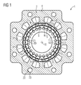
- FIG. 1 shows a cross section of an embodiment of an electric rotating machine 1 according to the invention.
- the electric rotating machine 1 has an external stator 2.
- the outer stator 2 has an iron core 4 which has a plurality of teeth 5 with grooves 6 therebetween. In the grooves 6 corresponding windings 3 are introduced.
- the windings 3 are usually electrically connected to a three-phase network, not shown here.
- a rotor 7 is arranged within the outer stator 2.
- the rotor 7 is arranged concentrically to the outer stator 2 about its axis of rotation 18. Between the rotor 7 and the outer stator 2 there is a second air gap 14.
- the rotor 7 has a carrier element 8, which is formed from a non-magnetic material.
- the support member 8 has a plurality of recesses, in each of which soft magnetic segments 9 are embedded. Furthermore, the electric rotating machine 1 has an inner stator 10.
- the inner stator 10 is arranged concentrically around the rotation axis 18 of the rotor 7 within the rotor 7.
- the inner stator 10 comprises a laminated core 11, which has a plurality of recesses, in each of which a permanent magnet 12 is arranged, wherein the permanent magnets 12 directly with the laminated core 11 of the inner stator 10 connected are.
- Each individual permanent magnet 12 is laterally magnetized, that is, one can imagine in this respect a bar magnet, whose ends, ie the poles facing each other - in extreme cases almost collapsed, and has on the inner air gap 13 side facing a north pole N and a south pole S. on.
- This has the advantage that the magnetic material is reduced to the permeated through the field lines materials of the permanent magnet and no magnetic inference is necessary as in classic permanent magnets on, for example, an iron package. Therefore, the laminated core 11 of the inner stator 10 may be made of aluminum or another, even non-magnetic, light metal.
- an electric rotating machine 1 having an outer stator 2, an inner stator 10 arranged concentrically with the outer stator 2, and a rotor 7 arranged concentrically with the outer stator 2 and with the inner stator 10 between the outer stator 2 and the inner stator 10 is also called a double-rotor machine.
- the laterally magnetized permanent magnets 12 of the electric rotating machine 1 in FIG. 1 are designed shell-shaped, but it is also possible, for example, a lenticular or trapezoidal design.
- a magnetic pole N or S of the inner stator 7 is formed by two contiguous poles N, N or S, S of a permanent magnet 12.
- the permanent magnets 12 are further designed such that the remote from the inner air gap 13 portion of the permanent magnets 12 substantially follows the magnetic preferred direction 26.
- the permanent magnets 12 may for example be made of a ferrite and / or contain, for example, neodymium-iron-boron.
- the rotor 7 has 17 soft-magnetic segments 9.
- the number of poles acting outwards corresponds to the number of pole pairs of the rotor.
- the electric machine 1 in FIG. 1 has a first cooling device 20 for cooling the inner stator 10.
- the first cooling device 20 comprises a plurality of cooling tubes 21, which are arranged within the laminated core 11 of the inner stator 12. Due to the possibility to produce the laminated core 11 of the inner stator 12, for example, aluminum, the cooling of the directly attached to the laminated core 11 of the inner stator 12 permanent magnets 12 is particularly efficient, since aluminum has a greater thermal conductivity than, for example, iron from which the laminated core 11 is usually made ,
- the cooling tubes 21 are arranged distributed uniformly in the circumferential direction of the inner stator 12 and extend along the axial direction of the electric rotating machine 1.
- the first cooling device 20 is provided for cooling the permanent magnets 12.
- the electric machine 1 comprises a second cooling device 22.
- the second cooling device 22 also comprises a plurality of cooling tubes 23, which extend along the axial direction of the electric machine.
- the cooling tubes 23 of the second cooling device 22 along the circumferential direction of the outer stator 2 are arranged evenly distributed.
- the cooling tubes 21, 23 may be traversed by a cooling medium, in particular a cooling liquid.
- the windings 3 of the outer stator 2 can be cooled.
- the first cooling device 20 the heat generated during operation of the electric machine 1, be discharged from the inner stator 10. In this way it can be prevented that the permanent magnets 9 overheat and thus be demagnetized.
- the electric rotating machine 1 has a second cooling device 22.
- the second cooling device 22 has a plurality of cooling tubes 23 extending along the axial direction of the electric machine.
- the cooling tubes 23 of the second cooling device 22 along the circumferential direction of the outer stator 2 are arranged evenly distributed.
- the cooling tubes 21, 23 may be traversed by a cooling medium, in particular a cooling liquid.
- the windings 3 of the outer stator 2 can be cooled.
- the first cooling device 20 the heat generated during operation of the electric machine 1, be discharged from the inner stator 10. In this way it can be prevented that the permanent magnets 9 overheat and thus be demagnetized.
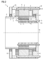
- FIG. 2 shows a longitudinal section of the embodiment of the electric rotating machine 1 according to FIG. 1 ,
- a housing 24 of the electric rotating machine 1 is shown.
- the housing 24 has a first flange 15, which is also called AS flange, and a second flange 16, which is also called BS flange on.
- a first bearing 17 is arranged, which is formed for example as a ball bearing.
- a second bearing element 19 is arranged, which may also be formed as a ball bearing.
- a shaft is connected, which is not shown.
- FIG. 3 shows a perspective view of a portion of an inner stator 12 with a lens-shaped laterally magnetized permanent magnet 12.
- the lens shape which corresponds to the shape of a biconvex lens, resulting from the fact that the shape of the inner air gap 13 facing portion 25 and the shape of the laminated core 11 facing portion are round, wherein the laminated core 11 facing and the inner air gap 13 facing away from section 25 of the magnetic preferred direction 26 follows.
- the lenticular laterally magnetized permanent magnets 12 of the inner stator 10 are arranged almost completely in the circumferential direction and cover the outer tangential surface of the inner stator 10, which corresponds to the outer surface of a formed from the lenticular laterally magnetized permanent magnet 12 and the laminated core 11, almost complete.
- a magnetic north pole N or south pole S of the inner stator 10 is formed by two contiguous poles N, N or S, S of the permanent magnets 12. A skewing and / or staggering of the magnetic poles, viewed over the axial length of the rotor 7, is possible.
- FIG. 4 shows a cross section of a portion of an inner stator 10 with trapezoidal laterally magnetized permanent magnet 12.
- the trapezoidal shape results from the fact that the shape of the laminated core 11 facing and the inner air gap 13 facing away portion, for example, for reasons of manufacturing process, is trapezoidal. Decisive in this case too is that the lateral magnetization of the trapezoidal permanent magnets 12 does not require any additional return material within the inner stator 10, since both the magnetic pole formation and the magnetic field guidance take place in the permanent magnet 12 itself.
- a magnetic north pole N or south pole S of the inner stator 10 is also formed here by two contiguous poles N, N or S, S of the permanent magnets 12. A skew and / or graduation of the magnetic poles, viewed over the axial length of the rotor 7, is also possible here.
- FIG. 5 shows a perspective view of a portion of an inner stator 10 with shell-shaped laterally magnetized permanent magnet 12.
- This further embodiment of a laterally magnetized permanent magnet 12 differs from that in FIG. 3 shown lens form in that in addition to the inner air gap 13 facing portion 25 is a concave recess from which results in a shell shape of the laterally magnetized permanent magnet 12.
- the sections to the left and right of the recess form the round shape of the inner stator 10.
- a magnetic north pole N or south pole S of the inner stator 10 is formed by two contiguous poles N, N or S, S of the permanent magnets 12.
- a skewing and / or staggering of the magnetic poles, viewed over the axial length of the rotor 7, is also possible here.
- FIG. 6 shows a longitudinal section of a nacelle of a wind turbine 27, wherein in the wind turbine 27, an embodiment of an electric rotating machine 1 according to the invention is used.
- the electric rotating machine 1 used as a generator can be driven directly (as a direct drive) or via a transmission.
- Such an electric rotating machine 1 preferably has a high polarity, which is particularly important for directly driven generators and preferably has a comparatively high air gap induction, which in turn increases the energy efficiency of the wind turbine 27.
- FIG. 7 shows a longitudinal section of an electrically driven vehicle 28, wherein in the vehicle 28, an embodiment of an electric rotating machine 1 according to the invention is used.
- the electric rotating machine 1 used as a motor can also be used together with an internal combustion engine, for example in a hybrid vehicle.
- the invention relates to an electric rotating machine 1 having an outer stator 2, an inner stator 10 which is arranged concentrically to the outer stator 2 within the outer stator 2, a rotor 7 which concentric with the outer stator 2 and the inner stator 10 between the outer stator 2 and the Inner stator 10 is disposed and which is movable relative to the outer stator 2 and the inner stator 10 and an inner air gap 13 which is disposed between the rotor 7 and the inner stator 10, wherein the inner stator 10 has a plurality of permanent magnets 12.
- each individual permanent magnet 12 has a north pole N and a south pole S on the side facing the internal air gap 13.
Landscapes
- Engineering & Computer Science (AREA)
- Power Engineering (AREA)
- Mechanical Engineering (AREA)
- Chemical & Material Sciences (AREA)
- Combustion & Propulsion (AREA)
- Life Sciences & Earth Sciences (AREA)
- Sustainable Development (AREA)
- Sustainable Energy (AREA)
- General Engineering & Computer Science (AREA)
- Transportation (AREA)
- Permanent Field Magnets Of Synchronous Machinery (AREA)
- Permanent Magnet Type Synchronous Machine (AREA)
- Iron Core Of Rotating Electric Machines (AREA)
Priority Applications (8)
| Application Number | Priority Date | Filing Date | Title |
|---|---|---|---|
| EP15162240.4A EP3076529A1 (fr) | 2015-04-01 | 2015-04-01 | Machine électrique tournante dotée d'aimants lenticulaires magnétisés latéralement |
| EP15176678.9A EP2991196A3 (fr) | 2014-09-01 | 2015-07-14 | Aimant permanent pour un rotor d'une machine électrique |
| CN201510526758.3A CN105391204B (zh) | 2014-09-01 | 2015-08-25 | 用于电机的转子的永磁铁及其应用、转子和电机 |
| US14/840,939 US20160065014A1 (en) | 2014-09-01 | 2015-08-31 | Permanent magnet for a rotor of an electric machine |
| JP2015170839A JP2016052249A (ja) | 2014-09-01 | 2015-08-31 | 電気機械の回転子用の永久磁石 |
| CN201610192156.3A CN106059224A (zh) | 2015-04-01 | 2016-03-30 | 具有横向磁化的透镜形磁体的旋转电机 |
| US15/087,464 US20160294229A1 (en) | 2015-04-01 | 2016-03-31 | Electric rotating machine with laterally magnetized magnets |
| US16/040,170 US10211691B2 (en) | 2014-09-01 | 2018-07-19 | Permanent magnet rotor for an electric machine |
Applications Claiming Priority (1)
| Application Number | Priority Date | Filing Date | Title |
|---|---|---|---|
| EP15162240.4A EP3076529A1 (fr) | 2015-04-01 | 2015-04-01 | Machine électrique tournante dotée d'aimants lenticulaires magnétisés latéralement |
Publications (1)
| Publication Number | Publication Date |
|---|---|
| EP3076529A1 true EP3076529A1 (fr) | 2016-10-05 |
Family
ID=52823488
Family Applications (1)
| Application Number | Title | Priority Date | Filing Date |
|---|---|---|---|
| EP15162240.4A Withdrawn EP3076529A1 (fr) | 2014-09-01 | 2015-04-01 | Machine électrique tournante dotée d'aimants lenticulaires magnétisés latéralement |
Country Status (3)
| Country | Link |
|---|---|
| US (1) | US20160294229A1 (fr) |
| EP (1) | EP3076529A1 (fr) |
| CN (1) | CN106059224A (fr) |
Cited By (3)
| Publication number | Priority date | Publication date | Assignee | Title |
|---|---|---|---|---|
| WO2017167710A1 (fr) | 2016-03-30 | 2017-10-05 | Siemens Aktiengesellschaft | Ensemble rotor |
| EP3393022A1 (fr) * | 2017-04-21 | 2018-10-24 | Siemens Aktiengesellschaft | Machine linaire électrique |
| WO2021063501A1 (fr) * | 2019-10-02 | 2021-04-08 | Wilo Se | Rotor à excitation permanente à géométrie d'aimant améliorée |
Families Citing this family (11)
| Publication number | Priority date | Publication date | Assignee | Title |
|---|---|---|---|---|
| EP3139474A1 (fr) | 2015-09-02 | 2017-03-08 | Siemens Aktiengesellschaft | Machine electrique et procede de fonctionnement d'une telle machine electrique et procede de fabrication |
| CN106972666B (zh) * | 2017-04-27 | 2019-06-14 | 哈尔滨工业大学 | 一种油冷、低耗外转子永磁电机 |
| US10615663B2 (en) | 2018-02-09 | 2020-04-07 | Deere & Company | Electrical motor cooling design |
| US20200055403A1 (en) * | 2018-08-14 | 2020-02-20 | Josiah Lamar Overstreet | High Efficiency Aerodynamic Vehcular Power System |
| JP2020188560A (ja) * | 2019-05-13 | 2020-11-19 | 株式会社エクセディ | 回転電機 |
| WO2020245392A1 (fr) * | 2019-06-05 | 2020-12-10 | Universiteit Gent | Machine électrique comprenant un ressort de torsion magnétique intégré |
| US12218555B2 (en) * | 2019-12-20 | 2025-02-04 | Vam Co., Ltd. | Dual and multiple air gap rotary device |
| JP7413042B2 (ja) * | 2020-01-24 | 2024-01-15 | 三菱重工業株式会社 | 外径側磁石界磁及び磁気歯車 |
| EP4146420A4 (fr) | 2020-05-05 | 2024-06-05 | Advanced Magnet Lab, Inc. | Procédé pour la fabrication continue d'aimants permanents |
| AU2022208708A1 (en) | 2021-01-14 | 2023-07-20 | Advanced Magnet Lab, Inc. | Electrical machines using axially-magnetized curvilinear permanent magnets |
| CN115296500B (zh) * | 2022-08-29 | 2024-07-30 | 山东大学 | 双定子低速永磁同步电机及驱动方法 |
Citations (10)
| Publication number | Priority date | Publication date | Assignee | Title |
|---|---|---|---|---|
| DE2550702A1 (de) * | 1975-11-12 | 1977-05-18 | Vyzk Vyvojovy Ustav Elektric | Elektrische gleichpolmaschine mit einem zahnlaeufer |
| DE2756626A1 (de) * | 1977-12-19 | 1979-06-21 | Philips Patentverwaltung | Rotor und verfahren zu seiner herstellung |
| JP2003124019A (ja) * | 2001-10-18 | 2003-04-25 | Yaskawa Electric Corp | 永久磁石とそれを用いた回転形モータのロータ |
| EP1475880A2 (fr) * | 2003-05-08 | 2004-11-10 | Corac Group plc | Roteur à aimants permanents |
| DE102004014985A1 (de) * | 2004-03-26 | 2005-10-27 | Minebea Co., Ltd. | Rotoranordnung für einen Elektromotor und Verfahren zu deren Herstellung |
| US20120217834A1 (en) * | 2011-02-28 | 2012-08-30 | Uqm Technologies Inc. | Brushless pm machine construction enabling low coercivity magnets |
| EP2528207A1 (fr) | 2011-05-23 | 2012-11-28 | Delphi Automotive Systems Luxembourg SA | Machine électrique sans balai |
| EP2770616A1 (fr) * | 2013-02-25 | 2014-08-27 | Siemens Aktiengesellschaft | Machine électrique avec stator séparé |
| DE102013007563A1 (de) * | 2013-05-02 | 2014-11-06 | Minebea Co., Ltd. | Rotor für eine elektrische Maschine |
| EP2806546A1 (fr) * | 2013-05-22 | 2014-11-26 | Siemens Aktiengesellschaft | Machine à aimants permanents à stator divisé |
Family Cites Families (10)
| Publication number | Priority date | Publication date | Assignee | Title |
|---|---|---|---|---|
| KR20010082212A (ko) * | 1998-09-26 | 2001-08-29 | 추후제출 | 동작장치 |
| JP3818059B2 (ja) * | 2000-12-27 | 2006-09-06 | 松下電工株式会社 | 公転式アクチュエータ |
| JP3716808B2 (ja) * | 2002-04-01 | 2005-11-16 | 日産自動車株式会社 | 回転電機 |
| US7154193B2 (en) * | 2004-09-27 | 2006-12-26 | General Electric Company | Electrical machine with double-sided stator |
| US7154191B2 (en) * | 2004-06-30 | 2006-12-26 | General Electric Company | Electrical machine with double-sided rotor |
| EP1917709A1 (fr) * | 2005-08-24 | 2008-05-07 | Kuhlmann-Wilsdorf Motors, LLC | Machines mp-a et mp-t, machines multipolaires pour des courants alternatifs et triphases |
| DE102011003831A1 (de) * | 2011-02-09 | 2012-08-09 | Robert Bosch Gmbh | Stator einer elektrischen Maschine |
| DE102011012453A1 (de) * | 2011-02-25 | 2012-08-30 | Nordex Energy Gmbh | Elektrische Maschine |
| JP2015061422A (ja) * | 2013-09-19 | 2015-03-30 | 株式会社デンソー | 動力伝達機構 |
| JP6448422B2 (ja) * | 2015-03-16 | 2019-01-09 | 株式会社Soken | マルチギャップ型回転電機 |
-
2015
- 2015-04-01 EP EP15162240.4A patent/EP3076529A1/fr not_active Withdrawn
-
2016
- 2016-03-30 CN CN201610192156.3A patent/CN106059224A/zh active Pending
- 2016-03-31 US US15/087,464 patent/US20160294229A1/en not_active Abandoned
Patent Citations (10)
| Publication number | Priority date | Publication date | Assignee | Title |
|---|---|---|---|---|
| DE2550702A1 (de) * | 1975-11-12 | 1977-05-18 | Vyzk Vyvojovy Ustav Elektric | Elektrische gleichpolmaschine mit einem zahnlaeufer |
| DE2756626A1 (de) * | 1977-12-19 | 1979-06-21 | Philips Patentverwaltung | Rotor und verfahren zu seiner herstellung |
| JP2003124019A (ja) * | 2001-10-18 | 2003-04-25 | Yaskawa Electric Corp | 永久磁石とそれを用いた回転形モータのロータ |
| EP1475880A2 (fr) * | 2003-05-08 | 2004-11-10 | Corac Group plc | Roteur à aimants permanents |
| DE102004014985A1 (de) * | 2004-03-26 | 2005-10-27 | Minebea Co., Ltd. | Rotoranordnung für einen Elektromotor und Verfahren zu deren Herstellung |
| US20120217834A1 (en) * | 2011-02-28 | 2012-08-30 | Uqm Technologies Inc. | Brushless pm machine construction enabling low coercivity magnets |
| EP2528207A1 (fr) | 2011-05-23 | 2012-11-28 | Delphi Automotive Systems Luxembourg SA | Machine électrique sans balai |
| EP2770616A1 (fr) * | 2013-02-25 | 2014-08-27 | Siemens Aktiengesellschaft | Machine électrique avec stator séparé |
| DE102013007563A1 (de) * | 2013-05-02 | 2014-11-06 | Minebea Co., Ltd. | Rotor für eine elektrische Maschine |
| EP2806546A1 (fr) * | 2013-05-22 | 2014-11-26 | Siemens Aktiengesellschaft | Machine à aimants permanents à stator divisé |
Cited By (3)
| Publication number | Priority date | Publication date | Assignee | Title |
|---|---|---|---|---|
| WO2017167710A1 (fr) | 2016-03-30 | 2017-10-05 | Siemens Aktiengesellschaft | Ensemble rotor |
| EP3393022A1 (fr) * | 2017-04-21 | 2018-10-24 | Siemens Aktiengesellschaft | Machine linaire électrique |
| WO2021063501A1 (fr) * | 2019-10-02 | 2021-04-08 | Wilo Se | Rotor à excitation permanente à géométrie d'aimant améliorée |
Also Published As
| Publication number | Publication date |
|---|---|
| CN106059224A (zh) | 2016-10-26 |
| US20160294229A1 (en) | 2016-10-06 |
Similar Documents
| Publication | Publication Date | Title |
|---|---|---|
| DE102004017157B4 (de) | Verfahren zur Herstellung einer Rotoranordnung und Rotoranordnung für eine elektrische Maschine | |
| EP3131189B1 (fr) | Rotor d'une machine electrique | |
| DE102022201589A1 (de) | Rotoranordnung für eine fremderregte Synchronmaschine | |
| DE102015111480A1 (de) | Rotor und elektrische Maschine | |
| DE102014101330B4 (de) | Maschine mit innenliegenden Permanentmagneten | |
| DE102021102807A1 (de) | Magneten, Polschuhe und Schlitzöffnungen eines Axialflussmotors | |
| EP2999087B1 (fr) | Machine électrique ayant une dispersion d'encoche magnétique faible | |
| DE102020129142B4 (de) | Läufer für eine rotierende elektrische Maschine | |
| WO2013135377A2 (fr) | Machine électrique efficace | |
| DE112010003859T5 (de) | Drehmotor vom Lundell-Typ | |
| DE112014006070B4 (de) | Elektromotor mit magnetischem Induktor und zugehöriges Herstellungsverfahren | |
| DE102008020779A1 (de) | Rotor mit einzelnen Teilsegmenten und elektrische Maschine | |
| EP3231070B1 (fr) | Moteur électrique à excitation permanente | |
| DE102011088370A1 (de) | Elektrischer Motor mit eingebetteten Permanentmagneten | |
| DE102019206460B3 (de) | Drehende Mehrphasen-Transversalflussmaschine | |
| DE102011105867A1 (de) | Rotor für eine elektrische Maschine | |
| DE102021211050A1 (de) | Elektromotor mit verschiedenen aufeinandergestapelten rotorsegmenten und verfahren zum ausgestalten desselben | |
| EP2928052A1 (fr) | Machine électrique dotée d'un stator interne excité par aimants permanents et d'un stator ayant des enroulement | |
| EP2770616A1 (fr) | Machine électrique avec stator séparé | |
| WO2014090440A2 (fr) | Machine asynchrone à répartition optimisée des pertes électriques entre le stator et le rotor | |
| DE102023129635A1 (de) | Hybrid erregte rotierende maschine | |
| DE102007018930A1 (de) | Elektrische Maschine mit aus Blechen zusammengesetzten Zähnen | |
| WO2005109610A1 (fr) | Unite modulaire stator | |
| EP3219000B1 (fr) | Machine électrique | |
| DE102017101913A1 (de) | Elektromotor mit eingebettetem Dauermagnet |
Legal Events
| Date | Code | Title | Description |
|---|---|---|---|
| PUAI | Public reference made under article 153(3) epc to a published international application that has entered the european phase |
Free format text: ORIGINAL CODE: 0009012 |
|
| AK | Designated contracting states |
Kind code of ref document: A1 Designated state(s): AL AT BE BG CH CY CZ DE DK EE ES FI FR GB GR HR HU IE IS IT LI LT LU LV MC MK MT NL NO PL PT RO RS SE SI SK SM TR |
|
| AX | Request for extension of the european patent |
Extension state: BA ME |
|
| 17P | Request for examination filed |
Effective date: 20170404 |
|
| RBV | Designated contracting states (corrected) |
Designated state(s): AL AT BE BG CH CY CZ DE DK EE ES FI FR GB GR HR HU IE IS IT LI LT LU LV MC MK MT NL NO PL PT RO RS SE SI SK SM TR |
|
| RAP1 | Party data changed (applicant data changed or rights of an application transferred) |
Owner name: SIEMENS AKTIENGESELLSCHAFT |
|
| 17Q | First examination report despatched |
Effective date: 20190412 |
|
| STAA | Information on the status of an ep patent application or granted ep patent |
Free format text: STATUS: THE APPLICATION IS DEEMED TO BE WITHDRAWN |
|
| 18D | Application deemed to be withdrawn |
Effective date: 20190823 |