EP3076559A1 - Enveloppe de dispositif électronique portable - Google Patents
Enveloppe de dispositif électronique portable Download PDFInfo
- Publication number
- EP3076559A1 EP3076559A1 EP14865401.5A EP14865401A EP3076559A1 EP 3076559 A1 EP3076559 A1 EP 3076559A1 EP 14865401 A EP14865401 A EP 14865401A EP 3076559 A1 EP3076559 A1 EP 3076559A1
- Authority
- EP
- European Patent Office
- Prior art keywords
- electronic device
- portable electronic
- antenna
- device cover
- cover
- Prior art date
- Legal status (The legal status is an assumption and is not a legal conclusion. Google has not performed a legal analysis and makes no representation as to the accuracy of the status listed.)
- Granted
Links
Images



Classifications
-
- H—ELECTRICITY
- H01—ELECTRIC ELEMENTS
- H01Q—ANTENNAS, i.e. RADIO AERIALS
- H01Q1/00—Details of, or arrangements associated with, antennas
- H01Q1/12—Supports; Mounting means
- H01Q1/22—Supports; Mounting means by structural association with other equipment or articles
- H01Q1/24—Supports; Mounting means by structural association with other equipment or articles with receiving set
- H01Q1/241—Supports; Mounting means by structural association with other equipment or articles with receiving set used in mobile communications, e.g. GSM
- H01Q1/242—Supports; Mounting means by structural association with other equipment or articles with receiving set used in mobile communications, e.g. GSM specially adapted for hand-held use
- H01Q1/243—Supports; Mounting means by structural association with other equipment or articles with receiving set used in mobile communications, e.g. GSM specially adapted for hand-held use with built-in antennas
-
- H—ELECTRICITY
- H01—ELECTRIC ELEMENTS
- H01Q—ANTENNAS, i.e. RADIO AERIALS
- H01Q1/00—Details of, or arrangements associated with, antennas
- H01Q1/12—Supports; Mounting means
- H01Q1/22—Supports; Mounting means by structural association with other equipment or articles
- H01Q1/24—Supports; Mounting means by structural association with other equipment or articles with receiving set
-
- H—ELECTRICITY
- H01—ELECTRIC ELEMENTS
- H01Q—ANTENNAS, i.e. RADIO AERIALS
- H01Q1/00—Details of, or arrangements associated with, antennas
- H01Q1/12—Supports; Mounting means
- H01Q1/22—Supports; Mounting means by structural association with other equipment or articles
- H01Q1/24—Supports; Mounting means by structural association with other equipment or articles with receiving set
- H01Q1/241—Supports; Mounting means by structural association with other equipment or articles with receiving set used in mobile communications, e.g. GSM
- H01Q1/242—Supports; Mounting means by structural association with other equipment or articles with receiving set used in mobile communications, e.g. GSM specially adapted for hand-held use
- H01Q1/245—Supports; Mounting means by structural association with other equipment or articles with receiving set used in mobile communications, e.g. GSM specially adapted for hand-held use with means for shaping the antenna pattern, e.g. in order to protect user against rf exposure
-
- H—ELECTRICITY
- H01—ELECTRIC ELEMENTS
- H01Q—ANTENNAS, i.e. RADIO AERIALS
- H01Q1/00—Details of, or arrangements associated with, antennas
- H01Q1/50—Structural association of antennas with earthing switches, lead-in devices or lightning protectors
-
- H—ELECTRICITY
- H01—ELECTRIC ELEMENTS
- H01Q—ANTENNAS, i.e. RADIO AERIALS
- H01Q9/00—Electrically-short antennas having dimensions not more than twice the operating wavelength and consisting of conductive active radiating elements
- H01Q9/04—Resonant antennas
- H01Q9/0407—Substantially flat resonant element parallel to ground plane, e.g. patch antenna
- H01Q9/0414—Substantially flat resonant element parallel to ground plane, e.g. patch antenna in a stacked or folded configuration
-
- H—ELECTRICITY
- H01—ELECTRIC ELEMENTS
- H01Q—ANTENNAS, i.e. RADIO AERIALS
- H01Q9/00—Electrically-short antennas having dimensions not more than twice the operating wavelength and consisting of conductive active radiating elements
- H01Q9/04—Resonant antennas
- H01Q9/30—Resonant antennas with feed to end of elongated active element, e.g. unipole
- H01Q9/42—Resonant antennas with feed to end of elongated active element, e.g. unipole with folded element, the folded parts being spaced apart a small fraction of the operating wavelength
-
- H—ELECTRICITY
- H04—ELECTRIC COMMUNICATION TECHNIQUE
- H04B—TRANSMISSION
- H04B1/00—Details of transmission systems, not covered by a single one of groups H04B3/00 - H04B13/00; Details of transmission systems not characterised by the medium used for transmission
- H04B1/38—Transceivers, i.e. devices in which transmitter and receiver form a structural unit and in which at least one part is used for functions of transmitting and receiving
-
- H—ELECTRICITY
- H04—ELECTRIC COMMUNICATION TECHNIQUE
- H04B—TRANSMISSION
- H04B1/00—Details of transmission systems, not covered by a single one of groups H04B3/00 - H04B13/00; Details of transmission systems not characterised by the medium used for transmission
- H04B1/38—Transceivers, i.e. devices in which transmitter and receiver form a structural unit and in which at least one part is used for functions of transmitting and receiving
- H04B1/3827—Portable transceivers
- H04B1/3888—Arrangements for carrying or protecting transceivers
-
- H—ELECTRICITY
- H04—ELECTRIC COMMUNICATION TECHNIQUE
- H04M—TELEPHONIC COMMUNICATION
- H04M1/00—Substation equipment, e.g. for use by subscribers
- H04M1/02—Constructional features of telephone sets
- H04M1/0202—Portable telephone sets, e.g. cordless phones, mobile phones or bar type handsets
- H04M1/026—Details of the structure or mounting of specific components
Definitions
- the present invention relates to a portable electronic device cover.
- a portable electronic device As a portable electronic device, a smart phone having various additional functions such as web surfing as well as communication information transmission and reception is widely used.
- an external antenna device such as an initial rod antenna device or helical antenna device has been used, but when the portable electronic device drops, the external antenna device becomes a weakest portion and deteriorates portability and thus a built-in antenna device has been recently used.
- a portable electronic device cover In order to protect components mounted at the inside and the outside of the portable electronic device from an external impact and a friction, a portable electronic device cover has been widely used as an accessory.
- a portable electronic device cover performs a function as an auxiliary battery for charging the portable electronic device as well as a function of protecting the portable electronic device from an external impact and enables the portable electronic device to perform a new function when mounting the portable electronic device cover in the portable electronic device.
- the portable electronic device cover despite the function of the portable electronic device cover, when the portable electronic device cover is mounted in the portable electronic device, a problem exists that the portable electronic device cover deteriorates a performance of an antenna device housed in the portable electronic device. For this reason, a producer of the portable electronic device designs the portable electronic device to maximize a radiation performance of the antenna device in a state in which the portable electronic device cover is not mounted in the portable electronic device. However, when the portable electronic device cover is mounted in the portable electronic device, a characteristic, for example, a resonant frequency band of the antenna device is changed due to the portable electronic device cover and thus a radiation performance of the antenna device may be deteriorated.
- a method of providing a physical space in a portable electronic device cover as the conventional art has a limitation due to a spatial restriction within the portable electronic device cover, and by providing a physical space, a cover design may be deteriorated.
- the present invention has been made in view of the above problems and provides a portable electronic device cover that improves a performance of an antenna device mounted within a portable electronic device while preventing damage and maintaining a design of the portable electronic device as an intrinsic function of the portable electronic device cover.
- a portable electronic device cover includes: a conductive plate separated by a predetermined distance from an antenna mounted in a portable electronic device and disposed at a location overlapped with at least a portion of the antenna, when the portable electronic device is mounted in the portable electronic device cover.
- a portable electronic device cover improves a performance of an antenna device mounted within a portable electronic device, thereby providing excellent usability.
- FIG. 1 is a diagram illustrating a portable electronic device 100 and a portable electronic device cover according to an exemplary embodiment of the present invention.
- the portable electronic device 100 may house an antenna 110.
- the antenna 110 may radiate a signal to transmit to the air and receive a signal radiated to the air.
- Such an antenna 110 may be disposed at a lower portion of the portable electronic device 100.
- a disposition of the antenna 110 within the portable electronic device 100 is not limited thereto and the antenna 110 may be disposed at an upper portion or the center of the portable electronic device 100.
- the antenna 110 may include at least two antenna patterns.
- the at least two antenna patterns may operate at each frequency domain within different resonant frequency bands, i.e., at different frequency domains.
- one antenna pattern may operate at a relatively low frequency domain corresponding to 800 to 1000Mhz, and the other antenna pattern may operate at a relatively high frequency domain corresponding to 1700 to 2500Mhz.
- Such an antenna pattern may have various forms in length, volume, and shape according to a support communication method.
- the antenna pattern may have a length, volume, and shape that supports the GSM communication method and may have a length, volume, and shape that supports the WCDMA1 communication method.
- Such an antenna 110 may be a Planer Inverted F Antenna (PIFA) type, Inverted F Antenna (IFA) type, or combination type thereof.
- PIFA Planer Inverted F Antenna
- IFA Inverted F Antenna
- such an antenna type is an illustration and the present invention is not limited thereto.
- the portable electronic device cover 120 may have a size that covers a circumferential edge of the portable electronic device 100. Further, in order to protect the portable electronic device 100 from an external impact or scratch, the portable electronic device cover 120 may be made of at least one of rubber, urethane, silicon, leather, synthetic leather, and fiber or a combination material thereof. However, this is an illustration and the portable electronic device cover 120 may be made of more various materials.
- the portable electronic device cover 120 may include a conductive plate 130 inserted into the portable electronic device cover 120 or attached to be exposed to the outside of the portable electronic device cover 120.
- the conductive plate 130 may perform a function of improving a performance of the antenna 110.
- a producer thereof designs the portable electronic device 100 to maximize an antenna performance in a state in which the portable electronic device cover 120 is not attached.
- the portable electronic device cover 120 When the portable electronic device cover 120 is mounted in the portable electronic device 100, the portable electronic device cover 120 made of a material having a high dielectric constant is located at a periphery of the antenna 110 and thus a change may occur in a resonant frequency band in which the antenna 110 operates.
- the conductive plate 130 minimizes movement of a resonant frequency band of the antenna 110 due to mounting of the portable electronic device cover 120, thereby reducing antenna performance deterioration.
- a location of an antenna 110(B) designated by a dotted line represents an antenna pattern location relative to the portable electronic device cover 120 in a state in which the portable electronic device 100 is mounted in the portable electronic device cover 120.
- the conductive plate 130 may be disposed within the portable electronic device cover 120 in a form that covers at least a portion of an antenna pattern of the antenna 110(B) designated by a dotted line.
- the conductive plate 130 may be disposed within the portable electronic device cover 120 to cover a portion B, for example, a portion formed in a shape ' ⁇ ' or 'U', in which the antenna pattern is extended by folding or bending, as shown in 103.
- a portion B for example, a portion formed in a shape ' ⁇ ' or 'U', in which the antenna pattern is extended by folding or bending, as shown in 103.
- 105 represents a side surface of a state in which the portable electronic device 100 is mounted in the portable electronic device cover 120 according to an exemplary embodiment of the present invention.
- the conductive plate 130 may be disposed within the portable electronic device cover 120 with separated by a predetermined distance d in a form that covers a portion A in which an antenna pattern is extended by folding or bending.
- a predetermined distance d in which the conductive plate 130 and the antenna pattern are separated may be exposed within the portable electronic device cover 120 or may be 1mm or less. That is, the predetermined distance d maybe 0-1mm.
- the portable electronic device cover 120 may be a battery pack or a view cover in addition to a protective cover for preventing damage of the portable electronic device 100.
- the portable electronic device cover 120 may be implemented in a battery pack form for charging a battery within the portable electronic device 100.
- the portable electronic device cover 120 may be formed in a view cover form that detaches an original cover of the portable electronic device 100 located at a rear surface of the portable electronic device 100 and attached to the portable electronic device 100. In this way, when the portable electronic device 100 is implemented in a battery pack or a view cover form, a length, volume, and shape of the conductive plate 130 may be adaptively formed to improve an antenna pattern performance.
- FIG. 2 is a diagram illustrating an antenna and a conductive plate according to an exemplary embodiment of the present invention.
- the antenna 110 may include a first antenna pattern 210, second antenna pattern 220, and power supply unit 230.
- the first antenna pattern 210 may radiate a signal in a relatively low resonant frequency band corresponding to 800Mhz to 1000Mhz.
- the first antenna pattern 210 may radiate a signal in a Global System for Mobile (GSM) communication band corresponding to 824Mhz to 894Mhz and an Extension of Global System for Mobile (EGSM) communication band corresponding to 880Mhz to 960Mhz.
- GSM Global System for Mobile
- EGSM Extension of Global System for Mobile
- the first antenna pattern 210 may correspond to a portion 210-1 that encloses the outside of the antenna 110 from the power supply unit 230.
- the second antenna pattern 220 may radiate a signal in a relatively high resonant frequency band corresponding to 1700Mhz to 2500Mhz.
- the second antenna pattern 220 may radiate a signal in a Digital Cordless System (DCS) communication band corresponding to 1710Mhz to 1880Mhz, a Personal Communication System (PCS) communication band corresponding to 1850Mhz to 1990Mhz, and a Wideband Code Division Multiple Access (WCDMA) 1 communication band corresponding to 1920Mhz to 2170Mhz.
- DCS Digital Cordless System
- PCS Personal Communication System
- WCDMA Wideband Code Division Multiple Access
- the second antenna pattern 220 may correspond to an area from a portion 230-1 including the power supply unit 230 to a portion 220-1 formed at the inside of the antenna 110.
- a length and form of the first antenna pattern 210 and the second antenna pattern 220 are an illustration, and the first antenna pattern 210 and the second antenna pattern 220 may have various lengths and forms.
- the antenna 110 includes the first antenna pattern 210 and the second antenna pattern 220, but the present invention is not limited thereto. In other words, the antenna 110 may include only one antenna pattern or at least three antenna patterns.
- the antenna 110 may include only the first antenna pattern 210, and when the portable electronic device 100 supports a communication method having a resonant frequency band from 800Mhz to 2500Mhz, the antenna 110 may further include another antenna pattern in addition to the first antenna pattern 210 and the second antenna pattern 220.
- the conductive plate 130 may be disposed within the portable electronic device cover 120 with separated by a predetermined distance from the first antenna pattern 210 in a form that covers a portion of the first antenna pattern 210, for example, a portion in which the first antenna pattern 210 is extended by folding or bending.
- Equation 1 when the portable electronic device 100 is mounted in the portable electronic device cover 120, a dielectric constant ⁇ of the first antenna pattern 210 may increase due to the portable electronic device cover 120.
- the resonant frequency f may reduce with increase of the dielectric constant ⁇ of the first antenna pattern 210.
- an electrical length of the first antenna pattern 210 can be reduced.
- Equation 1 when the dielectric constant ⁇ , magnetic permeability ⁇ , and light velocity C are fixed, an electrical length of the first antenna pattern 210 is inversely proportional to the resonant frequency f. Therefore, as an electrical length of the first antenna pattern 210 reduces, a resonant frequency may increase. Accordingly, the conductive plate 130 prevents a resonant frequency band in which the first antenna pattern 210 operates from moving to a lower frequency band, thereby preventing a radiation performance of the first antenna pattern 210 from deteriorating.
- the conductive plate 130 may be disposed within the portable electronic device cover 120 with separated by a predetermined distance from the first antenna pattern 210 in a form that covers a portion in which the first antenna pattern 210 is extended by folding or bending. As the conductive plate 130 is disposed in a form that covers a portion in which the first antenna pattern 210 is extended by folding or bending, compared with a case in which the conductive plate 130 is disposed in a form that covers a constantly extended first antenna pattern portion, the conductive plate 130 can further improve a performance of the first antenna pattern 210.
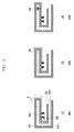
- 205 represents an effect according to disposition of the conductive plate 130 shown in 203. More specifically, as the conductive plate 130 is disposed as shown in 203, a capacitor 240 is connected between the first antenna pattern 210, i.e., a capacitance component occurs between the first antenna pattern 210. Accordingly, an electrical length of the first antenna pattern 210 can be reduced.
- the conductive plate 130 is disposed within the portable electronic device cover 120 with separated by a predetermined distance from the first antenna pattern 210 in a form that covers a portion in which the first antenna pattern 210 is extended by folding or bending, compared with a case in which the conductive plate 130 is disposed in a form that covers a constantly extended antenna pattern portion, the conductive plate 130 can considerably reduce an electrical length of the first antenna pattern 210.
- the conductive plate 130 is illustrated in a relationship with the first antenna pattern 210. This is because when the portable electronic device 100 is mounted in the portable electronic device cover 120, the first antenna pattern 210 operating in a resonant frequency band of a low frequency band is largely affected, compared with a resonant frequency band of a high frequency band in relation to a change of a dielectric constant of the antenna 110. Therefore, it will become apparent to a person of ordinary skill in the art that the present invention may be applied to the second antenna pattern 220 operating in a resonant frequency band of a high frequency band. Further, a performance improving effect of the antenna 110 by the conductive plate 130 may be independent according to the first antenna pattern 210 and the second antenna pattern 220. Therefore, at least two conductive plates 130 may be disposed on each antenna pattern according to an exemplary embodiment.
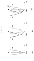
- FIG. 3 is a graph illustrating movement of a resonant frequency when mounting a portable electronic device cover according to an exemplary embodiment of the present invention.
- 310 is a graph representing a resonant frequency band in a state in which the portable electronic device 100 is not mounted in the portable electronic device cover 120.
- a resonant frequency band may be formed in about 890Mhz.
- a resonant frequency band may be formed in about 851 Mhz smaller than 890Mhz. Therefore, in an Extension of Global System for Mobile (EGSM) communication method, Total Isotropic Sensitivity (TIS) representing a receiving performance of the antenna 110 may be considerably reduced.
- EGSM Global System for Mobile
- a resonant frequency band may be formed in about 876Mhz larger than 851 Mhz . Accordingly, compared with a case in which the portable electronic device 100 is mounted in the portable electronic device cover 120 not including the conductive plate 130, by minimizing a movement of a resonant frequency, performance deterioration of the antenna 110 can be reduced.
- FIG. 4 is a graph and table illustrating an antenna performance change when mounting a portable electronic device cover according to an exemplary embodiment of the present invention.
- 401 of FIG. 4A illustrates graphs representing total radiation efficiency of the antenna 110, i.e., a rate of a signal amount actually radiated to the air to a signal amount input to the antenna 110.
- a rate of a signal amount actually radiated to the air to a signal amount input to the antenna 110 compared with a resonant frequency band segment C corresponding to an EGSM communication method, when the portable electronic device 100 is not mounted in the portable electronic device cover 120, in a graph 410, it can be seen that radiation efficiency is largest in an entire frequency band.
- a graph 430 represents that radiation efficiency increases a little.
- a graph 440 of a case in which the portable electronic device 100 according to an exemplary embodiment of the present invention is mounted in the portable electronic device cover 120 including the conductive plate 130
- the graph 420 of a case in which the portable electronic device 100 is mounted in the portable electronic device cover 120 and the graph 430 of a case of securing a physical space within the conventional portable electronic device cover 120 it can be seen that radiation efficiency is increased.
- 403 of FIG. 4A is graphs representing a reflection coefficient of the antenna 110, i.e., a rate of a returned signal amount (a reflected wave) to a signal amount (e.g., incident wave) input to the antenna 110.
- a resonant frequency band of about 890Mhz has a lowest reflection coefficient value.
- a resonant frequency band is formed about 851Mhz and thus compared with a case in which the portable electronic device 100 is not mounted in the portable electronic device cover 120, it can be seen that a resonant frequency band is very lowly formed, and it can be seen that a resonant frequency band of about 851Mhz has a very large reflection coefficient value.
- a resonant frequency band is formed about 855Hz and has a large reflection coefficient value.
- the portable electronic device 100 when the portable electronic device 100 according to an exemplary embodiment of the present invention is mounted in the portable electronic device cover 120 including the conductive plate 130, as can be seen in a graph 440-1, compared with the graph 420-1 of a case in which the portable electronic device 100 is mounted in the portable electronic device cover 120 and the graph 430-1 of a case in which the portable electronic device 100 secures a physical space within the conventional portable electronic device cover 120, a resonant frequency band is formed about 876Mhz and a reflection coefficient value is largely lowered, and thus it can be seen that performance deterioration of the antenna 110 can be minimized.
- FIG. 4B represents a Table comparing antenna efficiency, Total Radiated Power (TRP) as a transmitting performance, and Total Isotropic Sensitivity (TIS) as a receiving performance in a case in which the portable electronic device 100 is not mounted in the portable electronic device cover 120, a case in which the portable electronic device 100 is mounted in the portable electronic device cover 120, a case of securing a physical space within the portable electronic device 100 as the conventional art, and a case of mounting the portable electronic device cover 120 including the conductive plate 130 according to an exemplary embodiment of the present invention, in an EGSM communication method of the portable electronic device 100.
- TRP Total Radiated Power
- TIS Total Isotropic Sensitivity
- FIG. 4B compared with a case in which the portable electronic device 100 is mounted in the portable electronic device cover 120 and a case of securing a physical space within the portable electronic device 100 as the conventional art, in a case of mounting the portable electronic device cover 120 including the conductive plate 130, it can be seen that antenna efficiency increases. Further, in TIS as a receiving performance of the antenna 110, in a case in which the portable electronic device 100 is mounted in the portable electronic device cover 120, a performance is deteriorated by 6.1dB, compared with a case in which the portable electronic device 100 is not mounted in the portable electronic device cover 120, but in a case of mounting the portable electronic device cover 120 including the conductive plate 130, it can be seen that a performance is enhanced by 2.5dB.
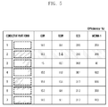
- FIG. 5 is a table comparing an antenna performance according to a form of the conductive plate 130 according to an exemplary embodiment of the present invention.
- a horizontal axis of the table represents a GSM communication method and an EGSM communication method operating in a relatively low resonant frequency band and a DCS communication method and a WCDMA1 communication method operating in a relatively high resonant frequency band.
- a vertical axis of the table represents a form such as a location and area of the conductive plate 130 according to an exemplary embodiment of the present invention. It is assumed that the conductive plate 130 is disposed in a form that covers a portion of the first antenna pattern 210 that radiates a signal in a resonant frequency band of a low frequency band.
- 1 represents a case in which the portable electronic device 100 is not mounted in the portable electronic device cover 120.
- FIG. 2 represents a case in which the conductive plate 130 is disposed in a form that covers an entire upper portion of the first antenna pattern 210 of 203 by including a portion in which the first antenna pattern 210 is extended by folding or bending, as shown in 203 of FIG. 2 .
- 3 represents a case in which the conductive plate 130 is disposed in a form that covers a half of an upper portion of the first antenna pattern 210 by including a portion in which the first antenna pattern 210 is extended by folding or bending.
- 4 represents a case in which the conductive plate 130 is disposed in a form that covers only a portion in which the first antenna pattern 210 is extended by folding or bending.
- 5 represents a case in which the conductive plate 130 is disposed in a form that covers a half of an upper area of the first antenna pattern 210 by not including a portion in which the first antenna pattern 210 is extended by folding or bending.
- 6 represents a case in which the conductive plate 130 is disposed in a form that covers only an upper portion of the first antenna pattern 210 of 203
- 7 represents a case in which the conductive plate 130 is disposed in a form that covers only a lower portion of the first antenna pattern 210 of 203.
- the second conductive plate 130 having a size and location has largest efficiency in an EGSM communication method.
- the third conductive plate 130 having an area corresponding to a portion in which the first antenna pattern 210 is extended by folding or bending has large efficiency.
- the conductive plate 130 is disposed in a form that covers a predetermined area or more of a portion in which the first antenna pattern 210 is extended by folding or bending, the conductive plate 130 has large efficiency.
- the sixth conductive plate 130 and the seventh conductive plate 130 in which the conductive plate 130 have no area corresponding to a portion in which the first antenna pattern 210 is extended by folding or bending have lowest efficiency, except for a case of the first conductive plate 130.
- the conductive plate 130 according to an exemplary embodiment of the present invention having a predetermined area or more by including a portion in which the first antenna pattern 210 is extended by folding or bending have largest antenna efficiency.
- a portable electronic device cover improves a performance of the antenna 110 mounted within the portable electronic device 100, thereby providing excellent usability.
- the portable electronic device 100 may include various modules according to a providing form in addition to the antenna 110. That is, the portable electronic device 100 may further include constituent elements that are not described above, such as a short range communication module for short range communication, interface for data transmission and reception by a wire communication method or a wireless communication method of the portable electronic device 100, Internet communication module that performs an Internet function by communicating with an Internet network, and digital broadcasting module that performs digital broadcasting receiving and reproducing functions. Such constituent elements may be very variously changed according to a convergence trend of a digital device, and a constituent element of a level equivalent to that of the foregoing constituent elements may be further included in the device. Further, the portable electronic device 100 according to the present exemplary embodiment may exclude a specific constituent element from the configuration or may replace a specific constituent element with another constituent element according to a providing form. This may be easily understood to a person of ordinary skill in the art.
Landscapes
- Engineering & Computer Science (AREA)
- Computer Networks & Wireless Communication (AREA)
- Signal Processing (AREA)
- Telephone Set Structure (AREA)
- Support Of Aerials (AREA)
Applications Claiming Priority (2)
| Application Number | Priority Date | Filing Date | Title |
|---|---|---|---|
| KR1020130145604A KR102128272B1 (ko) | 2013-11-27 | 2013-11-27 | 휴대형 전자장치 커버 |
| PCT/KR2014/011457 WO2015080479A1 (fr) | 2013-11-27 | 2014-11-27 | Enveloppe de dispositif électronique portable |
Publications (3)
| Publication Number | Publication Date |
|---|---|
| EP3076559A1 true EP3076559A1 (fr) | 2016-10-05 |
| EP3076559A4 EP3076559A4 (fr) | 2017-07-26 |
| EP3076559B1 EP3076559B1 (fr) | 2021-02-17 |
Family
ID=53199366
Family Applications (1)
| Application Number | Title | Priority Date | Filing Date |
|---|---|---|---|
| EP14865401.5A Not-in-force EP3076559B1 (fr) | 2013-11-27 | 2014-11-27 | Enveloppe de dispositif électronique portable |
Country Status (5)
| Country | Link |
|---|---|
| US (1) | US10243257B2 (fr) |
| EP (1) | EP3076559B1 (fr) |
| KR (1) | KR102128272B1 (fr) |
| CN (1) | CN105765786B (fr) |
| WO (1) | WO2015080479A1 (fr) |
Families Citing this family (6)
| Publication number | Priority date | Publication date | Assignee | Title |
|---|---|---|---|---|
| KR101909532B1 (ko) * | 2015-12-22 | 2018-12-19 | 엘지전자 주식회사 | 전자 디바이스 |
| KR102601927B1 (ko) | 2017-01-05 | 2023-11-15 | 삼성전자주식회사 | 커버 및 이를 포함하는 전자 장치 |
| CN108732445A (zh) * | 2018-05-29 | 2018-11-02 | 北京小米移动软件有限公司 | 后盖检测方法及装置 |
| US11145959B1 (en) * | 2020-07-10 | 2021-10-12 | Zebra Technologies Corporation | Accessory configuration for enhancing wireless signal reception of a user device |
| CN213403085U (zh) * | 2020-09-30 | 2021-06-08 | 华为技术有限公司 | 后盖及终端 |
| US11863693B2 (en) * | 2021-10-05 | 2024-01-02 | Arthur Jason Nghiem | Passive directivity enhancement for wireless device |
Family Cites Families (14)
| Publication number | Priority date | Publication date | Assignee | Title |
|---|---|---|---|---|
| KR101132447B1 (ko) * | 2006-06-23 | 2012-03-30 | 엘지전자 주식회사 | 휴대 단말기 |
| KR101304035B1 (ko) * | 2007-08-24 | 2013-09-04 | 삼성전자주식회사 | 휴대용 통신 장치의 보호 커버 |
| US9172134B2 (en) | 2008-11-06 | 2015-10-27 | Antenna79, Inc. | Protective cover for a wireless device |
| KR101534505B1 (ko) | 2008-11-28 | 2015-07-09 | 엘지전자 주식회사 | 이동 단말기 |
| US8698677B2 (en) | 2010-04-09 | 2014-04-15 | Sony Corporation | Mobile wireless terminal and antenna device |
| US20110294542A1 (en) | 2010-05-27 | 2011-12-01 | Edgy Angel Productions Llc | Cell phone cover with integrated mirror and flip shield |
| US8248314B2 (en) | 2010-09-22 | 2012-08-21 | Ash Jr Daniel R | Inductively coupled signal booster for a wireless communication device and in combination therewith |
| US20120206303A1 (en) * | 2010-11-11 | 2012-08-16 | Ethertronics, Inc | Antenna system coupled to an external device |
| US8648752B2 (en) * | 2011-02-11 | 2014-02-11 | Pulse Finland Oy | Chassis-excited antenna apparatus and methods |
| KR101832961B1 (ko) | 2011-10-05 | 2018-02-28 | 엘지전자 주식회사 | 이동 단말기 |
| KR20130097954A (ko) * | 2012-02-27 | 2013-09-04 | 최상효 | 휴대단말용 케이스 |
| US8774716B2 (en) * | 2012-03-29 | 2014-07-08 | Auden Techno Corp. | Mobile terminal extension case |
| KR101203773B1 (ko) * | 2012-08-20 | 2012-11-21 | 백용승 | 돌출부 또는 돌출부재가 구비되는 바형 단말기용 보호 케이스 |
| US9153857B2 (en) * | 2012-11-15 | 2015-10-06 | Chih-Hao Teng | Method for enhancing signal strength in mobile communication device |
-
2013
- 2013-11-27 KR KR1020130145604A patent/KR102128272B1/ko not_active Expired - Fee Related
-
2014
- 2014-11-27 EP EP14865401.5A patent/EP3076559B1/fr not_active Not-in-force
- 2014-11-27 WO PCT/KR2014/011457 patent/WO2015080479A1/fr not_active Ceased
- 2014-11-27 US US15/038,848 patent/US10243257B2/en active Active
- 2014-11-27 CN CN201480064134.8A patent/CN105765786B/zh not_active Expired - Fee Related
Also Published As
| Publication number | Publication date |
|---|---|
| KR102128272B1 (ko) | 2020-06-30 |
| CN105765786A (zh) | 2016-07-13 |
| US10243257B2 (en) | 2019-03-26 |
| EP3076559B1 (fr) | 2021-02-17 |
| EP3076559A4 (fr) | 2017-07-26 |
| KR20150061454A (ko) | 2015-06-04 |
| WO2015080479A1 (fr) | 2015-06-04 |
| US20160380335A1 (en) | 2016-12-29 |
| CN105765786B (zh) | 2019-06-11 |
Similar Documents
| Publication | Publication Date | Title |
|---|---|---|
| US9985338B2 (en) | Mobile terminal | |
| US9041606B2 (en) | Uninterrupted bezel antenna | |
| CN103178325B (zh) | 松耦合无线电天线设备和方法 | |
| EP3076559B1 (fr) | Enveloppe de dispositif électronique portable | |
| KR102305113B1 (ko) | 안테나를 구비한 전자 장치를 위한 보조 장치 | |
| US9419328B2 (en) | Terminal device | |
| US7119748B2 (en) | Internal multi-band antenna with planar strip elements | |
| US9819071B2 (en) | Antenna apparatus and method of making same | |
| US9276320B2 (en) | Multi-band antenna | |
| US8988290B2 (en) | Apparatus and method of providing an apparatus | |
| US9455492B2 (en) | Multiband antenna arrangement | |
| US20110128190A1 (en) | Wireless communication terminal with a split multi-band antenna having a single rf feed node | |
| US10122069B2 (en) | Mobile terminal device | |
| US20160329627A1 (en) | Embedded antenna | |
| US20160111778A1 (en) | Multiple-Input Multiple-Output Antenna System and Apparatus | |
| CN103633450A (zh) | 一种天线及电子设备 | |
| US8698682B1 (en) | Media antenna for communication systems | |
| KR20090093525A (ko) | 다중 밴드 내장형 안테나를 구비한 휴대용 단말기 | |
| CN104577339A (zh) | 一种天线及电子设备 | |
| KR100965732B1 (ko) | 이엠아이(emi) 도료를 이용한 휴대 단말기의 안테나 튜닝 장치 | |
| CN111293419A (zh) | 紧凑型lte天线布置 | |
| KR101495787B1 (ko) | 광대역 안테나 | |
| WO2007136316A1 (fr) | Dispositif d'antenne et dispositif de communication radio portable comprenant un tel dispositif d'antenne | |
| Chou et al. | Planar compact WWAN Antenna for Netbook/eBook applications |
Legal Events
| Date | Code | Title | Description |
|---|---|---|---|
| PUAI | Public reference made under article 153(3) epc to a published international application that has entered the european phase |
Free format text: ORIGINAL CODE: 0009012 |
|
| 17P | Request for examination filed |
Effective date: 20160527 |
|
| AK | Designated contracting states |
Kind code of ref document: A1 Designated state(s): AL AT BE BG CH CY CZ DE DK EE ES FI FR GB GR HR HU IE IS IT LI LT LU LV MC MK MT NL NO PL PT RO RS SE SI SK SM TR |
|
| AX | Request for extension of the european patent |
Extension state: BA ME |
|
| DAX | Request for extension of the european patent (deleted) | ||
| A4 | Supplementary search report drawn up and despatched |
Effective date: 20170628 |
|
| RIC1 | Information provided on ipc code assigned before grant |
Ipc: H01Q 9/42 20060101ALI20170622BHEP Ipc: H01Q 9/04 20060101ALI20170622BHEP Ipc: H01Q 1/24 20060101ALI20170622BHEP Ipc: H04B 1/3888 20150101ALI20170622BHEP Ipc: H01Q 1/50 20060101ALI20170622BHEP Ipc: H04B 1/38 20150101AFI20170622BHEP |
|
| STAA | Information on the status of an ep patent application or granted ep patent |
Free format text: STATUS: EXAMINATION IS IN PROGRESS |
|
| 17Q | First examination report despatched |
Effective date: 20180522 |
|
| GRAP | Despatch of communication of intention to grant a patent |
Free format text: ORIGINAL CODE: EPIDOSNIGR1 |
|
| STAA | Information on the status of an ep patent application or granted ep patent |
Free format text: STATUS: GRANT OF PATENT IS INTENDED |
|
| INTG | Intention to grant announced |
Effective date: 20200901 |
|
| GRAS | Grant fee paid |
Free format text: ORIGINAL CODE: EPIDOSNIGR3 |
|
| GRAA | (expected) grant |
Free format text: ORIGINAL CODE: 0009210 |
|
| STAA | Information on the status of an ep patent application or granted ep patent |
Free format text: STATUS: THE PATENT HAS BEEN GRANTED |
|
| AK | Designated contracting states |
Kind code of ref document: B1 Designated state(s): AL AT BE BG CH CY CZ DE DK EE ES FI FR GB GR HR HU IE IS IT LI LT LU LV MC MK MT NL NO PL PT RO RS SE SI SK SM TR |
|
| REG | Reference to a national code |
Ref country code: GB Ref legal event code: FG4D |
|
| REG | Reference to a national code |
Ref country code: CH Ref legal event code: EP |
|
| REG | Reference to a national code |
Ref country code: DE Ref legal event code: R096 Ref document number: 602014074973 Country of ref document: DE |
|
| REG | Reference to a national code |
Ref country code: AT Ref legal event code: REF Ref document number: 1362849 Country of ref document: AT Kind code of ref document: T Effective date: 20210315 |
|
| REG | Reference to a national code |
Ref country code: IE Ref legal event code: FG4D |
|
| REG | Reference to a national code |
Ref country code: LT Ref legal event code: MG9D |
|
| REG | Reference to a national code |
Ref country code: NL Ref legal event code: MP Effective date: 20210217 |
|
| PG25 | Lapsed in a contracting state [announced via postgrant information from national office to epo] |
Ref country code: BG Free format text: LAPSE BECAUSE OF FAILURE TO SUBMIT A TRANSLATION OF THE DESCRIPTION OR TO PAY THE FEE WITHIN THE PRESCRIBED TIME-LIMIT Effective date: 20210517 Ref country code: NO Free format text: LAPSE BECAUSE OF FAILURE TO SUBMIT A TRANSLATION OF THE DESCRIPTION OR TO PAY THE FEE WITHIN THE PRESCRIBED TIME-LIMIT Effective date: 20210517 Ref country code: HR Free format text: LAPSE BECAUSE OF FAILURE TO SUBMIT A TRANSLATION OF THE DESCRIPTION OR TO PAY THE FEE WITHIN THE PRESCRIBED TIME-LIMIT Effective date: 20210217 Ref country code: FI Free format text: LAPSE BECAUSE OF FAILURE TO SUBMIT A TRANSLATION OF THE DESCRIPTION OR TO PAY THE FEE WITHIN THE PRESCRIBED TIME-LIMIT Effective date: 20210217 Ref country code: GR Free format text: LAPSE BECAUSE OF FAILURE TO SUBMIT A TRANSLATION OF THE DESCRIPTION OR TO PAY THE FEE WITHIN THE PRESCRIBED TIME-LIMIT Effective date: 20210518 Ref country code: PT Free format text: LAPSE BECAUSE OF FAILURE TO SUBMIT A TRANSLATION OF THE DESCRIPTION OR TO PAY THE FEE WITHIN THE PRESCRIBED TIME-LIMIT Effective date: 20210617 Ref country code: LT Free format text: LAPSE BECAUSE OF FAILURE TO SUBMIT A TRANSLATION OF THE DESCRIPTION OR TO PAY THE FEE WITHIN THE PRESCRIBED TIME-LIMIT Effective date: 20210217 |
|
| REG | Reference to a national code |
Ref country code: AT Ref legal event code: MK05 Ref document number: 1362849 Country of ref document: AT Kind code of ref document: T Effective date: 20210217 |
|
| PG25 | Lapsed in a contracting state [announced via postgrant information from national office to epo] |
Ref country code: SE Free format text: LAPSE BECAUSE OF FAILURE TO SUBMIT A TRANSLATION OF THE DESCRIPTION OR TO PAY THE FEE WITHIN THE PRESCRIBED TIME-LIMIT Effective date: 20210217 Ref country code: PL Free format text: LAPSE BECAUSE OF FAILURE TO SUBMIT A TRANSLATION OF THE DESCRIPTION OR TO PAY THE FEE WITHIN THE PRESCRIBED TIME-LIMIT Effective date: 20210217 Ref country code: LV Free format text: LAPSE BECAUSE OF FAILURE TO SUBMIT A TRANSLATION OF THE DESCRIPTION OR TO PAY THE FEE WITHIN THE PRESCRIBED TIME-LIMIT Effective date: 20210217 Ref country code: NL Free format text: LAPSE BECAUSE OF FAILURE TO SUBMIT A TRANSLATION OF THE DESCRIPTION OR TO PAY THE FEE WITHIN THE PRESCRIBED TIME-LIMIT Effective date: 20210217 Ref country code: RS Free format text: LAPSE BECAUSE OF FAILURE TO SUBMIT A TRANSLATION OF THE DESCRIPTION OR TO PAY THE FEE WITHIN THE PRESCRIBED TIME-LIMIT Effective date: 20210217 |
|
| PG25 | Lapsed in a contracting state [announced via postgrant information from national office to epo] |
Ref country code: IS Free format text: LAPSE BECAUSE OF FAILURE TO SUBMIT A TRANSLATION OF THE DESCRIPTION OR TO PAY THE FEE WITHIN THE PRESCRIBED TIME-LIMIT Effective date: 20210617 |
|
| PG25 | Lapsed in a contracting state [announced via postgrant information from national office to epo] |
Ref country code: AT Free format text: LAPSE BECAUSE OF FAILURE TO SUBMIT A TRANSLATION OF THE DESCRIPTION OR TO PAY THE FEE WITHIN THE PRESCRIBED TIME-LIMIT Effective date: 20210217 Ref country code: EE Free format text: LAPSE BECAUSE OF FAILURE TO SUBMIT A TRANSLATION OF THE DESCRIPTION OR TO PAY THE FEE WITHIN THE PRESCRIBED TIME-LIMIT Effective date: 20210217 Ref country code: CZ Free format text: LAPSE BECAUSE OF FAILURE TO SUBMIT A TRANSLATION OF THE DESCRIPTION OR TO PAY THE FEE WITHIN THE PRESCRIBED TIME-LIMIT Effective date: 20210217 Ref country code: SM Free format text: LAPSE BECAUSE OF FAILURE TO SUBMIT A TRANSLATION OF THE DESCRIPTION OR TO PAY THE FEE WITHIN THE PRESCRIBED TIME-LIMIT Effective date: 20210217 |
|
| REG | Reference to a national code |
Ref country code: DE Ref legal event code: R097 Ref document number: 602014074973 Country of ref document: DE |
|
| PG25 | Lapsed in a contracting state [announced via postgrant information from national office to epo] |
Ref country code: SK Free format text: LAPSE BECAUSE OF FAILURE TO SUBMIT A TRANSLATION OF THE DESCRIPTION OR TO PAY THE FEE WITHIN THE PRESCRIBED TIME-LIMIT Effective date: 20210217 Ref country code: RO Free format text: LAPSE BECAUSE OF FAILURE TO SUBMIT A TRANSLATION OF THE DESCRIPTION OR TO PAY THE FEE WITHIN THE PRESCRIBED TIME-LIMIT Effective date: 20210217 Ref country code: DK Free format text: LAPSE BECAUSE OF FAILURE TO SUBMIT A TRANSLATION OF THE DESCRIPTION OR TO PAY THE FEE WITHIN THE PRESCRIBED TIME-LIMIT Effective date: 20210217 Ref country code: ES Free format text: LAPSE BECAUSE OF FAILURE TO SUBMIT A TRANSLATION OF THE DESCRIPTION OR TO PAY THE FEE WITHIN THE PRESCRIBED TIME-LIMIT Effective date: 20210217 |
|
| PLBE | No opposition filed within time limit |
Free format text: ORIGINAL CODE: 0009261 |
|
| STAA | Information on the status of an ep patent application or granted ep patent |
Free format text: STATUS: NO OPPOSITION FILED WITHIN TIME LIMIT |
|
| 26N | No opposition filed |
Effective date: 20211118 |
|
| PG25 | Lapsed in a contracting state [announced via postgrant information from national office to epo] |
Ref country code: AL Free format text: LAPSE BECAUSE OF FAILURE TO SUBMIT A TRANSLATION OF THE DESCRIPTION OR TO PAY THE FEE WITHIN THE PRESCRIBED TIME-LIMIT Effective date: 20210217 |
|
| PG25 | Lapsed in a contracting state [announced via postgrant information from national office to epo] |
Ref country code: SI Free format text: LAPSE BECAUSE OF FAILURE TO SUBMIT A TRANSLATION OF THE DESCRIPTION OR TO PAY THE FEE WITHIN THE PRESCRIBED TIME-LIMIT Effective date: 20210217 |
|
| PG25 | Lapsed in a contracting state [announced via postgrant information from national office to epo] |
Ref country code: IT Free format text: LAPSE BECAUSE OF FAILURE TO SUBMIT A TRANSLATION OF THE DESCRIPTION OR TO PAY THE FEE WITHIN THE PRESCRIBED TIME-LIMIT Effective date: 20210217 |
|
| PG25 | Lapsed in a contracting state [announced via postgrant information from national office to epo] |
Ref country code: IS Free format text: LAPSE BECAUSE OF FAILURE TO SUBMIT A TRANSLATION OF THE DESCRIPTION OR TO PAY THE FEE WITHIN THE PRESCRIBED TIME-LIMIT Effective date: 20210617 |
|
| PG25 | Lapsed in a contracting state [announced via postgrant information from national office to epo] |
Ref country code: MC Free format text: LAPSE BECAUSE OF FAILURE TO SUBMIT A TRANSLATION OF THE DESCRIPTION OR TO PAY THE FEE WITHIN THE PRESCRIBED TIME-LIMIT Effective date: 20210217 |
|
| REG | Reference to a national code |
Ref country code: CH Ref legal event code: PL |
|
| PG25 | Lapsed in a contracting state [announced via postgrant information from national office to epo] |
Ref country code: LU Free format text: LAPSE BECAUSE OF NON-PAYMENT OF DUE FEES Effective date: 20211127 Ref country code: BE Free format text: LAPSE BECAUSE OF NON-PAYMENT OF DUE FEES Effective date: 20211130 |
|
| REG | Reference to a national code |
Ref country code: BE Ref legal event code: MM Effective date: 20211130 |
|
| PG25 | Lapsed in a contracting state [announced via postgrant information from national office to epo] |
Ref country code: IE Free format text: LAPSE BECAUSE OF NON-PAYMENT OF DUE FEES Effective date: 20211127 |
|
| PG25 | Lapsed in a contracting state [announced via postgrant information from national office to epo] |
Ref country code: FR Free format text: LAPSE BECAUSE OF NON-PAYMENT OF DUE FEES Effective date: 20211130 |
|
| PGFP | Annual fee paid to national office [announced via postgrant information from national office to epo] |
Ref country code: GB Payment date: 20221020 Year of fee payment: 9 Ref country code: DE Payment date: 20220621 Year of fee payment: 9 |
|
| PG25 | Lapsed in a contracting state [announced via postgrant information from national office to epo] |
Ref country code: HU Free format text: LAPSE BECAUSE OF FAILURE TO SUBMIT A TRANSLATION OF THE DESCRIPTION OR TO PAY THE FEE WITHIN THE PRESCRIBED TIME-LIMIT; INVALID AB INITIO Effective date: 20141127 |
|
| PG25 | Lapsed in a contracting state [announced via postgrant information from national office to epo] |
Ref country code: CY Free format text: LAPSE BECAUSE OF FAILURE TO SUBMIT A TRANSLATION OF THE DESCRIPTION OR TO PAY THE FEE WITHIN THE PRESCRIBED TIME-LIMIT Effective date: 20210217 |
|
| PG25 | Lapsed in a contracting state [announced via postgrant information from national office to epo] |
Ref country code: LI Free format text: LAPSE BECAUSE OF NON-PAYMENT OF DUE FEES Effective date: 20220630 Ref country code: CH Free format text: LAPSE BECAUSE OF NON-PAYMENT OF DUE FEES Effective date: 20220630 |
|
| PG25 | Lapsed in a contracting state [announced via postgrant information from national office to epo] |
Ref country code: MK Free format text: LAPSE BECAUSE OF FAILURE TO SUBMIT A TRANSLATION OF THE DESCRIPTION OR TO PAY THE FEE WITHIN THE PRESCRIBED TIME-LIMIT Effective date: 20210217 |
|
| REG | Reference to a national code |
Ref country code: DE Ref legal event code: R119 Ref document number: 602014074973 Country of ref document: DE |
|
| GBPC | Gb: european patent ceased through non-payment of renewal fee |
Effective date: 20231127 |
|
| PG25 | Lapsed in a contracting state [announced via postgrant information from national office to epo] |
Ref country code: MT Free format text: LAPSE BECAUSE OF FAILURE TO SUBMIT A TRANSLATION OF THE DESCRIPTION OR TO PAY THE FEE WITHIN THE PRESCRIBED TIME-LIMIT Effective date: 20210217 |
|
| PG25 | Lapsed in a contracting state [announced via postgrant information from national office to epo] |
Ref country code: DE Free format text: LAPSE BECAUSE OF NON-PAYMENT OF DUE FEES Effective date: 20240601 |
|
| PG25 | Lapsed in a contracting state [announced via postgrant information from national office to epo] |
Ref country code: GB Free format text: LAPSE BECAUSE OF NON-PAYMENT OF DUE FEES Effective date: 20231127 |
|
| PG25 | Lapsed in a contracting state [announced via postgrant information from national office to epo] |
Ref country code: GB Free format text: LAPSE BECAUSE OF NON-PAYMENT OF DUE FEES Effective date: 20231127 Ref country code: DE Free format text: LAPSE BECAUSE OF NON-PAYMENT OF DUE FEES Effective date: 20240601 |
|
| PG25 | Lapsed in a contracting state [announced via postgrant information from national office to epo] |
Ref country code: TR Free format text: LAPSE BECAUSE OF FAILURE TO SUBMIT A TRANSLATION OF THE DESCRIPTION OR TO PAY THE FEE WITHIN THE PRESCRIBED TIME-LIMIT Effective date: 20210217 |