EP3076565B1 - Répéteur optique pour réseaux sous-marins - Google Patents
Répéteur optique pour réseaux sous-marins Download PDFInfo
- Publication number
- EP3076565B1 EP3076565B1 EP15305483.8A EP15305483A EP3076565B1 EP 3076565 B1 EP3076565 B1 EP 3076565B1 EP 15305483 A EP15305483 A EP 15305483A EP 3076565 B1 EP3076565 B1 EP 3076565B1
- Authority
- EP
- European Patent Office
- Prior art keywords
- optical
- coupler
- repeater
- upstream
- terminal unit
- Prior art date
- Legal status (The legal status is an assumption and is not a legal conclusion. Google has not performed a legal analysis and makes no representation as to the accuracy of the status listed.)
- Active
Links
Images

Classifications
-
- H—ELECTRICITY
- H04—ELECTRIC COMMUNICATION TECHNIQUE
- H04B—TRANSMISSION
- H04B10/00—Transmission systems employing electromagnetic waves other than radio-waves, e.g. infrared, visible or ultraviolet light, or employing corpuscular radiation, e.g. quantum communication
- H04B10/07—Arrangements for monitoring or testing transmission systems; Arrangements for fault measurement of transmission systems
- H04B10/075—Arrangements for monitoring or testing transmission systems; Arrangements for fault measurement of transmission systems using an in-service signal
- H04B10/079—Arrangements for monitoring or testing transmission systems; Arrangements for fault measurement of transmission systems using an in-service signal using measurements of the data signal
- H04B10/0795—Performance monitoring; Measurement of transmission parameters
- H04B10/07955—Monitoring or measuring power
-
- H—ELECTRICITY
- H04—ELECTRIC COMMUNICATION TECHNIQUE
- H04J—MULTIPLEX COMMUNICATION
- H04J14/00—Optical multiplex systems
- H04J14/02—Wavelength-division multiplex systems
- H04J14/0221—Power control, e.g. to keep the total optical power constant
-
- H—ELECTRICITY
- H04—ELECTRIC COMMUNICATION TECHNIQUE
- H04B—TRANSMISSION
- H04B10/00—Transmission systems employing electromagnetic waves other than radio-waves, e.g. infrared, visible or ultraviolet light, or employing corpuscular radiation, e.g. quantum communication
- H04B10/07—Arrangements for monitoring or testing transmission systems; Arrangements for fault measurement of transmission systems
- H04B10/075—Arrangements for monitoring or testing transmission systems; Arrangements for fault measurement of transmission systems using an in-service signal
- H04B10/079—Arrangements for monitoring or testing transmission systems; Arrangements for fault measurement of transmission systems using an in-service signal using measurements of the data signal
- H04B10/0791—Fault location on the transmission path
-
- H—ELECTRICITY
- H04—ELECTRIC COMMUNICATION TECHNIQUE
- H04B—TRANSMISSION
- H04B10/00—Transmission systems employing electromagnetic waves other than radio-waves, e.g. infrared, visible or ultraviolet light, or employing corpuscular radiation, e.g. quantum communication
- H04B10/29—Repeaters
Definitions
- the invention relates to the technical field of undersea communications system, especially optical repeaters.
- a conventional undersea communications system includes components such as repeaters to compensate for the attenuation of the optical signal, branching units to connect branch lines to a main trunk and hybrid optical and electrical cables which transmit both optical data signals and DC electrical power to supply power to the repeaters.
- Performance Monitoring In Undersea Lightwave Systems by Richard A. Jensen (XP032387751 ) discloses an undersea monitoring system for determining the location and nature of the failure so an appropriate repair can be planned and executed quickly in the event of a failure, for example an external aggression from ship anchors.
- the monitoring system may use the command/response channel systems by way of instrumentation in each undersea amplifier pair to locally measure amplifier parameters.
- measurement commands are sent to the repeaters using low frequency tone bursts that are impressed as amplitude modulation on the high speed data traffic. Only one amplifier is queried at a time.
- US-A-5440418 relates to an optical repeater that transmits management information.
- the management information includes an ID code for an optical repeater which has failed and the status of the failure.
- EP-A-1959587 describes an optical amplifier in accordance with the preamble of claim 1, which is configured to transmit an indication signal carrying alarm suppression information.
- aspects of the disclosure are based on the idea of enabling a fastest restoration of optical communications in a submarine optical network when a cable trunk section fault occurs.
- the invention provides an optical repeater as defined in claim 1.
- the optical repeater automatically sends a signaling message to terminal units of the submarine optical network when a cable trunk section fault occurs near the optical repeater.
- the optical repeater is implemented for bidirectional transmissions.
- the optical repeater further comprises:
- optical repeater is bidirectional.
- such an optical repeater can comprise one or more of the features below.
- the pumping module may be made in various manners.
- the pumping module is optical.
- the modulation unit may be made in various manners.
- the modulation unit is configured to modulate a driving current of the pumping module.
- the modulation unit is a variable power attenuator arranged for attenuating the pumping power of the pumping module.
- the modulation unit is a variable power attenuator arranged for attenuating the optical amplifier output power.
- the pumping module comprises one or more pump laser sources.
- the optical amplifier may be made in various manners.
- the optical amplifier comprises a Doped Fiber Amplifier (DFA).
- the optical amplifier comprises an Erbium Doped Fiber Amplifier (EDFA).
- the optical amplifier comprises a Raman amplifier.
- the optical amplifier comprises a hybrid Raman-EDFA amplifier mixing distributed Raman amplification and a EDFA amplifier.
- the modulation unit operates at a modulation frequency comprised within the frequency range : 10kHz to 200kHz.
- the modulation unit may operate with diverse modulation schemes.
- the modulation unit applies an Amplitude Shift Keying (ASK) modulation.
- the modulation unit applies a Binary Amplitude Shift Keying (BASK) modulation.
- ASK Amplitude Shift Keying
- BASK Binary Amplitude Shift Keying
- the optical detector may be implemented in diverse manners.
- the upstream optical detector comprises a photodiode.
- the optical repeater further comprises:
- the optical repeater may be employed in various optical networks.
- the optical repeater is employed in a terrestrial optical network or preferably a submarine optical network.
- the invention also provides a submarine optical network comprising an optical repeater above described, the submarine optical network further comprising:
- the management system is directly connected to the first terminal unit and/or second terminal unit by a backup terrestrial network, and indirectly connected to all the terminal units through the submarine optical network.
- a submarine optical network can comprise one or more of the features below.
- the topology of the submarine optical network may be various.
- the submarine optical network comprises two terrestrial terminal units connected through an optical communication line, and a branching unit on the communication line for enabling adding and dropping functions to an off-shore third terminal unit by connecting the third terminal unit.
- the submarine optical network comprises a number of terminal units connected in series.
- the submarine optical network is a broadcast network.
- the management system is configured to collect any signaling message incoming from any optical repeater of the submarine optical network in order to transmit controlling messages to terminal units and eventually other instruction messages, for example to optical repeaters.
- the instruction messages are transmitted to an optical repeater through a terminal unit of the submarine optical network and are amplitude-modulated.
- the modulation frequency of an instruction message is comprised within a frequency range: 10kHz to 200kHz.
- the modulation is performed by a distributed Raman amplification in the terminal unit.
- the second optical fiber line comprises a plurality of optical add and drop multiplexing branching units, wherein the submarine optical network further comprises:
- the selected intermediary terminal unit is configured to: in response to receiving the controlling message, transmit to the optical amplifier of the second optical fiber line a loading signal carried on predefined loading channels of a wavelength division multiplexing (WDM) grid.
- WDM wavelength division multiplexing
- the first terminal unit transmits the incoming optical signal on first wavelength channels of the WDM grid, wherein the predefined loading channels are defined on a wavelength range that overlaps with the first wavelength channels.
- the monitoring unit provided in the optical repeater can serve a number of purposes.
- the monitoring unit is arranged to provide part or all of the control functions required by the different components of the optical repeater.
- the monitoring unit performs functions such as controlling the pumping module e.g. controlling a driving current of pump laser sources in the pumping module, controlling the signaling message encoder, controlling a controlling message and/ or instruction message decoder, etc.
- the monitoring unit shall allow the detection of an instruction signal sent by terminal equipement at a modulation frequency comprised within a frequency range: 10kHz to 200kHz.
- a monitoring unit can be designed as a unitary component, e.g. a printed circuit board, or as distributed components.
- the first and third optical fiber lines are included in a first bidirectional optical communication line.
- the first optical fiber line is intended to transmit optical signals in the opposite direction to the third optical fiber line.
- the second and fourth optical fiber lines are included in a second bidirectional optical communication line.
- the second optical fiber line is intended to transmit optical signals in the opposite direction to the fourth optical fiber line.
- optical fiber line and “optical communication line” are used to designate a set of optical components constituting a single-direction or bidirectional optical path for optical signals.
- Such components may be selected in the list consisting of: cable trunk sections comprising optical fibers, chromatic dispersion compensators, amplifiers, branching units, optical isolators, optical filters, optical equalizers, and the like.
- the network 1 comprises two Submarine Line Terminals Equipments (SLTEs) A, B connected by two optical communication lines 8 and 11 for transmitting optical WDM signals in a bidirectional manner.
- a Branching Unit (BU) 7 connects the optical communication line 8 to the optical communication line 11.
- the BU 7 allows dropping wavelength channels from the optical communication line 8 to an optical communication line 18 connecting a third SLTE C.
- the BU 7 also allows adding wavelength channels from an optical communication line 20 connecting the SLTE C to the communication line 11.
- the optical WDM signals transmitted by the SLTE A are multiplexed with the optical WDM signals transmitted by the SLTE C in the same optical communication line 11 in order to reach the SLTE B.
- the wavelength allocation may be configured in a fixed manner for each SLTE.
- the SLTE C is a terminal equipment which is located on an offshore plateform whereas the SLTEs A and B are located on a terrestrial place.
- the optical communication lines 8 and 11 are represented on Figure 1 for only one direction which will be referred to as the A-B direction in the following.
- the A-B direction is the direction of transmission of the optical WDM signals from the SLTE A to the SLTE B via the BU 7 within the optical communication lines 8 and 11.
- the optical communication lines 18 and 20 connecting the SLTE C to the BU 7 are represented for the only A-B direction.
- each optical communication line 8, 11, 18 and 20 of the network 1 is bidirectional.
- the communication line 18 between the SLTE A and the SLTE C allows transmitting incoming WDM signals from the SLTE A to the SLTE C.
- the communication line 20 between the SLTE C and the SLTE B allows transmitting incoming optical WDM signals from the SLTE C to the SLTE B.
- the optical WDM signals transmitted by the SLTE A will be further referred to as A-optical WDM signals
- the optical WDM signals transmitted by the SLTE C will be further referred to as C-optical WDM signals.
- the BU 7 comprises a splitter 17 in order to broadcast the A-optical WDM signal to the SLTEs B and C, and a coupler 19 in order to multiplex the A-optical WDM signals and the C-optical WDM signals in the optical communication line 11.
- the SLTE A is preconfigured for transmitting the A-optical WDM signals carried by wavelength channels 6 represented on the spectrum 5 on the A-B direction.
- the SLTE C is preconfigured for transmitting the C-optical WDM signals carried by wavelength channels 9 represented on the spectrum 5 on the A-B direction.
- the wavelength channels 6 and the wavelength channels 9 are disjoint.
- the optical communication line 8 comprises sequential undersea cable trunk sections 2, 3 and 4.
- Each cable trunk section comprises an optical fiber in each direction in order to allow transmitting the optical WDM signals in both the A-B direction and the B-A direction. Due to scattering and absorption, the power of the optical WDM signals lowers as it travels along an optical fiber.
- the A-optical WDM signals should be periodically amplified along the optical communication line 8. Such an amplification is enabled by amplifiers arranged in optical repeaters.
- Two adjacent cable trunk sections, e.g. cable trunk sections 3 and 4 are plugged on both sides of a bidirectional repeater, e.g. repeater N+1, in order to amplify the optical WDM signals passing through.
- the cable trunk sections further comprise a conductive cable for supplying power to the repeaters, e.g. repeaters N and N+1.
- repeaters N, N+1 are represented on Figure 1 as unidirectional amplifiers in the A-B direction. However, the repeaters N, N+1 are bidirectional as it will later be described with reference to Figure 5 .
- Repairing the optical communication line 8 requires to identify which cable trunk section of the submarine optical network 1 is cut in order to fix it or to remove it and to replace it. Such an operation may be long.
- the SLTE C sends the C-optical WDM signal on the A-B direction on wavelength channels 9 represented on the spectrum 5 whereas the optical communication line 8 is cut on the cable trunk section 4. Due to the periodical repeaters M, M+1 on the optical communication line 11, the power of the C-optical WDM signal carried on the wavelength channels 9 is excessively amplified.
- the nominal amplification power of the repeaters M, M+1 is designed for being distributed on each wavelength channel of the spectrum 5 in order to amplify both the A-optical WDM signals and the C-optical WDM signals which are carried by the wavelength channels 6 and 9 of the spectrum 5.
- the A-optical WDM signals carried by the wavelength channels 6 are not transmitted any more because of the cable trunk section cut. Therefore, the repeaters M, M+1 are not working as designed, i.e. all the amplification power is distributed on the only C-optical WDM signals carried by the wavelength channels 9. Therefore, the power 13 of the C-optical WDM signals carried by the wavelength channels 9 incoming to the SLTE B is extremely higher than the nominal power 12. For example, the variation between the power 13 and the nominal power 12 is equal to 10dB. Due to the high power 13 of the WDM signal carried by the wavelength channels 9, the C-optical WDM signals carried by the wavelength channels 9 are degraded, namely because of non linear interactions which increase with a power increasing.
- the Bit Error Rate (BER) of the C-optical WDM signals therefore increases, or the transmission is entirely disrupted. Finally, the optical communication should be restored between the SLTE C and the SLTE B in order to restore the BER of the C-optical WDM signals.
- BER Bit Error Rate
- the repeater N+1 automatically transmits a signaling message to the SLTE B in order to inform the SLTE B that the neighbor cable trunk section 4 is cut.
- the repeater N+1 receives the A-optical WDM signals from the cable trunk section 4 which is cut. As the cable trunk section 4 is cut, the optical power of the A-optical WDM signals is very low or absent.
- the repeater N+1 automatically detects a power drop for the WDM signal received and therefore sends a signaling message 15 into the optical communication line 8.
- the signaling message comprises the address of the repeater N+1.
- the signaling message 15 is received by the SLTE B, and the SLTE B then transmits the signaling message 15 to a network management system (NMS) 22. which is connected to the SLTE B.
- NMS network management system
- the NMS 22 is connected to both SLTEs A and B through a back-up terrestrial network 60 and configured to collect all signaling messages from the SLTEs A and B, in order to send controlling messages to the SLTEs for restoring communication, when possible and when required.
- the NMS 22 collects signaling messages from the SLTEs A and B thanks to the back-up terrestrial network 60.
- the NMS 22 comprises a database in which is stored a topological map of the submarine optical network.
- the topological map comprises addresses and location information for optical repeaters N, N+1, M and M+1 and of the SLTEs A, B and C.
- the NMS 22 receives the signaling message 15 sent by the optical repeater N+1 via the SLTE B, and selects a SLTE of the submarine optical network as a function of the address of the optical repeater and of the location of the SLTE.
- the optical repeater which has sent the signaling message is the optical repeater N+1
- the NMS 22 determines that the A-optical WDM signals which are supposed to travel from the SLTE A to the SLTE B on the wavelength channels 6 are not transmitted anymore. Therefore, the NMS 22 selects the SLTE C which is located downstream of the SLTE A and sends a controlling message 21 to the SLTE C.
- the controlling message 21 is sent to the SLTE C via the SLTE B.
- the controlling message comprises the address of the SLTE C as well as an instruction, for the SLTE C, to add a loading signal on preconfigured wavelength channels.
- the NMS 22 sends the controlling message 21 to the submarine optical network 1 via the SLTE B.
- the controlling message 21 arrives to the SLTE C which recognizes the address and receives the instruction to add a loading signal on preconfigured wavelength channels in order to restore the optical communication between the SLTE C and the SLTE B.
- the preconfigured wavelength channels are the loading channels 14 represented on Figure 4 .
- the SLTE C is preconfigured to add the loading signal on these loading channels 14 in the A-B direction.
- Adding the loading signal on loading channels 14 in place of the missing A-optical WDM signals carried by the wavelength channels 6 allows restoring the optical communication between the SLTE C and the SLTE B. Indeed, replacing the missing A-optical WDM signals by the loading signal allows distributing the amplification power of the repeaters M, M+1 to both the C-optical WDM signals and to the loading signal. Thanks to the addition of the loading signal, the C-optical WDM signal retrieves a nominal power 12.
- the signaling message 15 is an amplitude-modulated optical message.
- the repeater N+1 is connected to the cable trunk section 4.
- the cable trunk section 4 comprises an upstream optical fiber 41 and a downstream optical fiber 42.
- the upstream optical fiber 41 transmits incoming optical signals from the SLTE A to the repeater N+1 whereas the downstream optical fiber 42 transmits optical signals in the opposite direction.
- the cable trunk section 4 is impaired by a cut on a point 10.
- the incoming optical signals are transmitted from an input of the repeater to an upstream coupler 26 in order to split the power of the incoming optical signals.
- the upstream coupler 26 is connected to an upstream photodiode 25 in order to monitor the upstream level of power of the incoming optical signals.
- the photodiode 25 is connected to a monitoring unit 29 whose purpose is to drive a pump control circuit 28 as represented by arrow 36.
- the upstream coupler is also connected to an Erbium Doped Fiber Amplifier (EDFA) 23 in order to amplify the incoming optical signals.
- the EDFA 23 is pumped by a laser pump 27, as represented by arrow 37. As represented by arrow 38, the laser pump 27 is powered by the pump control circuit 28.
- the incoming optical signals are amplified by the EDFA 23 and the downstream level of power is controlled thanks to a downstream coupler 31 which is connected to the output of the EDFA 23.
- the downstream coupler 31 splits the optical power of the amplified optical signals in order to transmit the amplified optical signals to the SLTE B and to monitor a downstream level of power of the amplified optical signals by way of a downstream photodiode 30.
- the downstream photodiode 30 is also connected to the pump control circuit 28 and to the monitoring unit 29.
- the upstream photodiode 25 detects that the upstream level of power of the incoming optical signals is lower than a threshold of -10 dB. Therefore, the pump control circuit 28 modulates the laser pump 27 in order to generate an amplitude-modulated signaling message 15 in the direction of the SLTE B.
- the the pump control circuit 28 operates at a modulation frequency comprised within the frequency range: 10kHz to 200kHz.
- the signaling message is Binary Amplitude Shift Keying (BASK) modulated and encodes the address of the repeater N+1.
- BASK Binary Amplitude Shift Keying
- the repeater also comprises an upstream coupler 33 connected to an upstream photodiode 32, a downstream coupler 34 connected to a downstream photodiode 35, the upstream and downstream photodiodes 32 and 35 being connected to the monitoring unit 29 in order to monitor the upstream and downstream level of power of optical signals propagating in the opposite direction, the optical signals being also amplified by an EDFA 24 which is also connected to and pumped by the laser pump 27. All these components operate in the same manner as described above, though for the reverse direction.
- the EDFA 23 and the EDFA 24 are pumped by the same laser pump 27. Due to the detection of a power drop by the photodiode 25 in the upstream direction, the laser pump 27 will cause the EDFA 23 and the EDFA 24 to generate the same amplitude-modulated message 15 in the two directions.
- the amplitude-modulated message 15 which propagates on the optical fiber 42 in the direction of the SLTE A is an amplitude-modulation of a WDM comb of the optical signals incoming from the SLTE B, whereas the amplitude-modulated message 15 which propagates on the optical communication line 11 is an amplitude-modulation of the amplified spontaneous emission (ASE), i.e. optical noise, in the EDFA 23.
- ASE amplified spontaneous emission
- a detection of a power drop by the photodiode 32 leads to the generation of the same amplitude-modulated message 15 in each direction.
- repeater N+1 may apply to all the repeaters N, M and M+1.
- the cabletrunk section 4 default (i.e. optical power drop) is detected simultaneously by the two adjacent repeaters N and N+1.
- the modulation circuits may include a temporization mechanism. This temporization mechanism will impose a time delay between the activation of the amplitude-modulated signaling messages sent by adjacent repeaters, thus avoiding any risk of detection disturbance of the signaling messages by the terminal units.
- the modulation unit temporization mechanism may be a fix setting or advantageously a setting configurable via the NMS.
- the SLTE C which is an offshore plateform, need not be directly connected to the NMS 22.
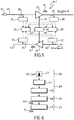
- a first step 43 an optical power of an incoming optical signal is detected.
- the optical power is converted in a voltage value V_Input Level.
- the first step 43 is performed by the upstream photodiode 25.
- a second step 44 the voltage value V_Input Level is compared to a threshold Vref.
- the second step 44 is performed by the monitoring unit 29.
- a third step 45 an electrical signaling message is automatically processed when the voltage value V_Input Level is below the threshold Vref.
- the third step 45 is performed by the monitoring unit 29.
- a fourth step 46 the electrical signaling message electrically drives the laser pump 27 for converting the electrical signaling message into an optical amplitude-modulated pumping 49.
- the fourth step 46 is performed by the pump control circuit 28.
- the optical amplitude-modulated pumping optically pumps the EDFA 23, which results in the generation of the amplitude-modulated signaling message 15.
- the NMS 22 communicates with the SLTE C thanks to a redondant satellite-based network.
- the NMS 22 thus automatically determines that the consequence of the lack of the WDM signal supposed to be carried on the wavelength channels 6 on the optical communication line 11 is an impairment of the WDM signal carried by the wavelength channels 9 which are sent to the SLTE B by the SLTE C.
- the SLTE C is located downstream of the repeater N+1 in the A-B direction. Therefore, the NMS 22 sends the controlling message 21 directly to the SLTE C thanks to a satellite-based communication.
- the submarine optical network 1 is reconfigurable instead of being fixed wavelength-allocated.
- the NMS 22 thus may comprise a datatable in which is stored a reconfigurable wavelength allocation map and the controlling message 21 thus comprises the instruction, for the SLTE C, of which wavelengths of a WDM comb are to be filled with a loading signal carried by loading channels.
- control unit and electronic devices could be e.g. hardware means like e.g. an ASIC, or a combination of hardware and software means, e.g. an ASIC and an FPGA, or at least one microprocessor and at least one memory with software modules located therein.
- a NMS can be a hardware device, for example a personal computer, a workstation, an Internet appliance, or other general purpose or specific purpose communications device.
- a software program running on this system performs network management functions to control the network elements.
Landscapes
- Engineering & Computer Science (AREA)
- Computer Networks & Wireless Communication (AREA)
- Signal Processing (AREA)
- Physics & Mathematics (AREA)
- Electromagnetism (AREA)
- Optical Communication System (AREA)
Claims (13)
- Répéteur optique (N+1) destiné à un réseau optique sous-marin, le répéteur optique comprenant :- un coupleur amont (26) disposant d'une entrée de coupleur, d'une première sortie de coupleur et d'une deuxième sortie de coupleur, l'entrée de coupleur du coupleur amont étant destinée à être connectée à une première ligne de fibre optique (41) pour recevoir un signal optique d'entrée provenant d'un premier terminal (A),- un amplificateur optique (23) conçu pour transmettre et amplifier le signal optique d'entrée, l'amplificateur optique (23) transmettant et amplifiant le signal optique d'entrée entre la première sortie de coupleur du coupleur amont et une sortie du répéteur, la sortie du répéteur étant destinée à être connectée à une deuxième ligne de fibre optique pour transmettre un signal optique amplifié à un deuxième terminal (B),- un détecteur optique amont (25) configuré pour détecter la puissance optique du signal optique d'entrée, le détecteur optique amont (25) étant connecté à la deuxième sortie de coupleur du coupleur amont,- un module de pompage (27) connecté à l'amplificateur optique pour fournir une puissance de pompage à l'amplificateur optique,- une unité de modulation (28) adaptée pour moduler la puissance de pompage (49) fournie par le module de pompage en réponse à la détection du fait que la puissance optique est en dessous d'un seuil prédéfini (45) pour générer ainsi un message de signalisation modulé en amplitude (15) transporté par le signal optique amplifié par l'amplificateur optique,- une unité de surveillance (29) connectée au détecteur optique amont et configurée pour activer l'unité de modulation (28) en réponse à la détection du fait que la puissance optique est en dessous du seuil prédéfini (45),caractérisé en ce que le répéteur optique comprend en outre :- un deuxième coupleur amont (33) disposant d'une entrée de coupleur, d'une première sortie de coupleur et d'une deuxième sortie de coupleur, l'entrée de coupleur du deuxième coupleur amont étant destinée à être connectée à une troisième ligne de fibre optique pour recevoir un deuxième signal optique d'entrée provenant du deuxième terminal (B),- une deuxième sortie de répéteur étant destinée à être connectée à une quatrième ligne de fibre optique pour transmettre un deuxième signal optique amplifié au premier terminal (A),- un deuxième amplificateur optique (24) conçu pour transmettre et amplifier le deuxième signal optique d'entrée entre la première sortie de coupleur du deuxième coupleur amont et la deuxième sortie du répéteur, le module de pompage optique (27) étant en outre connecté au deuxième amplificateur optique pour fournir une puissance de pompage au deuxième amplificateur optique (24),- un deuxième détecteur optique amont (32) connecté à la deuxième sortie de coupleur du deuxième coupleur amont, le deuxième détecteur optique amont étant configuré pour détecter une deuxième puissance optique du deuxième signal optique d'entrée, dans lequel l'unité de surveillance (29) est en outre connectée au deuxième détecteur optique amont et en outre configurée pour activer l'unité de modulation (28) en réponse à la détection du fait que la deuxième puissance optique est en dessous du seuil prédéfini,dans lequel l'unité de modulation (28) est adaptée pour moduler la puissance de pompage du module de pompage (29) pour générer un message de signalisation modulé en amplitude transporté à la fois par le signal optique amplifié par le premier amplificateur optique et le deuxième signal optique amplifié par le deuxième amplificateur optique, le message de signalisation comprenant un identifiant du répéteur optique.
- Répéteur optique selon la revendication 1, le répéteur optique comprenant en outre :- un coupleur aval (31) disposant d'une entrée de coupleur, d'une première sortie de coupleur et d'une deuxième sortie de coupleur, l'entrée de coupleur du coupleur aval étant connectée à l'amplificateur optique (23),- un détecteur optique aval (30), le détecteur optique aval étant connecté à la deuxième sortie de coupleur du coupleur aval, le détecteur optique aval étant configuré pour détecter une puissance optique amplifiée du signal optique amplifié par l'amplificateur optique (23),dans lequel la première sortie de coupleur du coupleur aval est connectée à la sortie du répéteur,
dans lequel le détecteur optique aval (30) est en outre connecté à l'unité de surveillance (29),
dans lequel l'unité de surveillance est en outre connectée au module de pompage (28),
l'unité de surveillance étant en outre configurée pour commander le module de pompage (27) pour adapter la puissance de pompage en fonction de la puissance optique amplifiée détectée. - Répéteur optique selon l'une quelconque des revendications 1 à 2, dans lequel l'unité de modulation est configurée pour moduler un courant de commande du module de pompage.
- Répéteur optique selon l'une quelconque des revendications 1 à 3, dans lequel l'unité de modulation est un atténuateur de puissance variable conçu pour atténuer la puissance de pompage du module de pompage.
- Répéteur optique selon l'une quelconque des revendications 1 à 4, dans lequel l'amplificateur optique comprend un amplificateur à fibre dopée à l'erbium (EFDA).
- Répéteur optique selon l'une quelconque des revendications 1 à 5, dans lequel l'amplificateur optique comprend un amplificateur Raman.
- Répéteur optique selon l'une quelconque des revendications 1 à 6, dans lequel l'unité de modulation applique une modulation par déplacement d'amplitude (ASK).
- Répéteur optique selon l'une quelconque des revendications 1 à 7, dans lequel l'unité de modulation applique une modulation par déplacement d'amplitude binaire (BASK).
- Répéteur optique selon l'une quelconque des revendications 1 à 8, dans lequel le détecteur optique amont comprend une photodiode.
- Réseau optique sous-marin (1) comprenant un répéteur optique (N+1) selon l'une quelconque des revendications 1 à 9, le réseau sous-marin comprenant en outre :- une première ligne de fibre optique (4, 41 et 42) connectée à l'entrée de coupleur du coupleur amont (26) du répéteur optique (N+1),- un premier terminal (A), le premier terminal étant connecté à la première ligne de fibre optique (4),- une deuxième ligne de fibre optique connectée à la sortie du répéteur, la deuxième ligne de fibre optique comprenant un amplificateur optique et une unité de branchement de multiplexeur à insertion-extraction optique (7),- un deuxième terminal (B), le deuxième terminal étant connecté à la deuxième ligne de fibre optique (11),- un terminal intermédiaire (C), le terminal intermédiaire étant connecté à l'unité de branchement de multiplexeur à insertion-extraction optique (7) pour extraire des signaux optiques de et insérer des signaux optiques dans la deuxième ligne de fibre optique,- un système de gestion (22) connecté au premier terminal et/ou au deuxième terminal et configuré pour :- transmettre un message de commande (21) au terminal intermédiaire (C) en réponse à la réception du message de signalisation (15) provenant du premier ou du deuxième terminal (A ou B).
- Réseau optique sous-marin selon la revendication 10, dans lequel la deuxième ligne de fibre optique comprend une pluralité d'unités de branchement de multiplexeur à insertion-extraction optique, le réseau sous-marin comprenant en outre :- une pluralité de terminaux intermédiaires, chacun connecté à la deuxième ligne de fibre optique par le biais d'une des unités de branchement de multiplexeur à insertion-extraction optique, dans lequel le système de gestion comprend une base de données dans laquelle est stockée une carte topologique du réseau sous-marin, la carte topologique comprenant des identifiants et des informations de localisation pour le répéteur optique et les terminaux intermédiaires du réseau sous-marin, le système de gestion étant configuré pour :- en réponse à la réception du message de signalisation provenant du premier ou du deuxième terminal,- sélectionner l'un des terminaux intermédiaires (C) du réseau sous-marin (1) en fonction de l'identifiant du répéteur et de la localisation du terminal intermédiaire (C) sur la carte topologique,- transmettre le message de commande (21) au terminal intermédiaire sélectionné (C).
- Réseau optique sous-marin (1) selon la revendication 10 ou 11, dans lequel le terminal intermédiaire est configuré pour :
en réponse à la réception du message de commande, transmettre à l'amplificateur optique de la deuxième ligne de fibre optique (11) un signal de charge transporté sur des canaux de charge prédéfinis (14) d'un réseau à multiplexage par répartition en longueur d'onde (WDM) (5). - Réseau optique sous-marin selon la revendication 12, dans lequel :le premier terminal transmet le signal optique d'entrée sur des premiers canaux de longueur d'onde (6) du réseau WDM,les canaux de charge prédéfinis (14) sont définis sur une plage de longueur d'onde qui chevauche les premiers canaux de longueur d'onde (6).
Priority Applications (1)
| Application Number | Priority Date | Filing Date | Title |
|---|---|---|---|
| EP15305483.8A EP3076565B1 (fr) | 2015-03-31 | 2015-03-31 | Répéteur optique pour réseaux sous-marins |
Applications Claiming Priority (1)
| Application Number | Priority Date | Filing Date | Title |
|---|---|---|---|
| EP15305483.8A EP3076565B1 (fr) | 2015-03-31 | 2015-03-31 | Répéteur optique pour réseaux sous-marins |
Publications (2)
| Publication Number | Publication Date |
|---|---|
| EP3076565A1 EP3076565A1 (fr) | 2016-10-05 |
| EP3076565B1 true EP3076565B1 (fr) | 2018-12-05 |
Family
ID=52946493
Family Applications (1)
| Application Number | Title | Priority Date | Filing Date |
|---|---|---|---|
| EP15305483.8A Active EP3076565B1 (fr) | 2015-03-31 | 2015-03-31 | Répéteur optique pour réseaux sous-marins |
Country Status (1)
| Country | Link |
|---|---|
| EP (1) | EP3076565B1 (fr) |
Families Citing this family (4)
| Publication number | Priority date | Publication date | Assignee | Title |
|---|---|---|---|---|
| WO2018210470A1 (fr) | 2017-05-17 | 2018-11-22 | Alcatel Lucent | Utilisation de filtres passe-bande dans des trajets de signaux de supervision d'un système de transport optique |
| EP3599726B1 (fr) | 2018-07-25 | 2021-05-19 | Alcatel Submarine Networks | Équipement de surveillance pour un système de transport optique |
| EP3696997B1 (fr) | 2019-02-15 | 2022-06-15 | Alcatel Submarine Networks | Circuit optique de surveillance symétrique pour un répétiteur optique bidirectionnel |
| CN117375724B (zh) * | 2023-12-06 | 2024-03-19 | 华海通信技术有限公司 | 一种水下设备以及通信系统 |
Citations (2)
| Publication number | Priority date | Publication date | Assignee | Title |
|---|---|---|---|---|
| US5440418A (en) * | 1992-07-15 | 1995-08-08 | Oki Electric Industry Co., Ltd. | Method and apparatus for alarm surveillance for an optical transmission system |
| EP1959587A1 (fr) * | 2005-12-09 | 2008-08-20 | Huawei Technologies Co., Ltd. | Procede, appareil, et systeme de traitement de panne de ligne a fibres optiques |
Family Cites Families (2)
| Publication number | Priority date | Publication date | Assignee | Title |
|---|---|---|---|---|
| US7218442B2 (en) * | 2005-03-04 | 2007-05-15 | Jds Uniphase Corporation | Optical communications system with fiber break detection in the presence of Raman amplification |
| US8139951B2 (en) * | 2008-06-26 | 2012-03-20 | Igor Samartsev | Fiber-optic long-haul transmission system |
-
2015
- 2015-03-31 EP EP15305483.8A patent/EP3076565B1/fr active Active
Patent Citations (2)
| Publication number | Priority date | Publication date | Assignee | Title |
|---|---|---|---|---|
| US5440418A (en) * | 1992-07-15 | 1995-08-08 | Oki Electric Industry Co., Ltd. | Method and apparatus for alarm surveillance for an optical transmission system |
| EP1959587A1 (fr) * | 2005-12-09 | 2008-08-20 | Huawei Technologies Co., Ltd. | Procede, appareil, et systeme de traitement de panne de ligne a fibres optiques |
Also Published As
| Publication number | Publication date |
|---|---|
| EP3076565A1 (fr) | 2016-10-05 |
Similar Documents
| Publication | Publication Date | Title |
|---|---|---|
| JP5195746B2 (ja) | 伝送路監視方法及び装置 | |
| US7103275B2 (en) | Optical transmission system | |
| JP6440127B2 (ja) | 光挿入分岐マルチプレクサ分岐ユニット | |
| US8867912B2 (en) | Optical service channel systems and methods over high loss links | |
| US8218964B2 (en) | All optical 1+1 protection unit using sub-carrier modulation protocol | |
| EP3469739B1 (fr) | Réseau de communication optique sous-marin | |
| CN108683460B (zh) | 光学模块、光通信系统和光通信方法 | |
| US8554070B2 (en) | Optical transmission apparatus and optical attenuation amount control method | |
| US20110058806A1 (en) | System and Method for Distributed Fault Sensing and Recovery | |
| EP3076565B1 (fr) | Répéteur optique pour réseaux sous-marins | |
| EP1959587A1 (fr) | Procede, appareil, et systeme de traitement de panne de ligne a fibres optiques | |
| US20220123834A1 (en) | Ramework for handling signal integrity using ase in optical networks | |
| US10615867B1 (en) | Optical amplifier signaling systems and methods for shutoff coordination and topology discovery | |
| JP2012109653A (ja) | 波長多重伝送装置 | |
| JP4467213B2 (ja) | 光伝送システム | |
| US6404527B1 (en) | Method and apparatus for transmitting a response signal from an optical repeater to a terminal requesting status information | |
| JP4172547B2 (ja) | 可変光学減衰器を用いた監視信号変調方式のためのシステムおよび方法 | |
| US7202995B2 (en) | Method and apparatus for communicating status in a lightwave communication system employing optical amplifiers | |
| EP1468512A1 (fr) | Systeme de transmissions optiques a amplificateurs de raman comprenant un systeme de supervision | |
| Bergano et al. | Submerged plant equipment | |
| JP2009267950A (ja) | 光通信システム及び光通信装置 | |
| CN115967437A (zh) | 自我修复的海底链路 | |
| JP7635850B2 (ja) | 光経路状態判定装置、光伝送システム、光経路状態判定方法、およびコンピュータプログラム | |
| JPH09116502A (ja) | 監視用ループバック回路を有する高出力光増幅中継器 | |
| JP4673285B2 (ja) | 光通信装置および光分岐・挿入装置 |
Legal Events
| Date | Code | Title | Description |
|---|---|---|---|
| PUAI | Public reference made under article 153(3) epc to a published international application that has entered the european phase |
Free format text: ORIGINAL CODE: 0009012 |
|
| AK | Designated contracting states |
Kind code of ref document: A1 Designated state(s): AL AT BE BG CH CY CZ DE DK EE ES FI FR GB GR HR HU IE IS IT LI LT LU LV MC MK MT NL NO PL PT RO RS SE SI SK SM TR |
|
| AX | Request for extension of the european patent |
Extension state: BA ME |
|
| STAA | Information on the status of an ep patent application or granted ep patent |
Free format text: STATUS: REQUEST FOR EXAMINATION WAS MADE |
|
| 17P | Request for examination filed |
Effective date: 20170405 |
|
| RBV | Designated contracting states (corrected) |
Designated state(s): AL AT BE BG CH CY CZ DE DK EE ES FI FR GB GR HR HU IE IS IT LI LT LU LV MC MK MT NL NO PL PT RO RS SE SI SK SM TR |
|
| STAA | Information on the status of an ep patent application or granted ep patent |
Free format text: STATUS: EXAMINATION IS IN PROGRESS |
|
| 17Q | First examination report despatched |
Effective date: 20180112 |
|
| RAP1 | Party data changed (applicant data changed or rights of an application transferred) |
Owner name: ALCATEL LUCENT |
|
| GRAP | Despatch of communication of intention to grant a patent |
Free format text: ORIGINAL CODE: EPIDOSNIGR1 |
|
| STAA | Information on the status of an ep patent application or granted ep patent |
Free format text: STATUS: GRANT OF PATENT IS INTENDED |
|
| INTG | Intention to grant announced |
Effective date: 20180626 |
|
| GRAS | Grant fee paid |
Free format text: ORIGINAL CODE: EPIDOSNIGR3 |
|
| GRAA | (expected) grant |
Free format text: ORIGINAL CODE: 0009210 |
|
| STAA | Information on the status of an ep patent application or granted ep patent |
Free format text: STATUS: THE PATENT HAS BEEN GRANTED |
|
| AK | Designated contracting states |
Kind code of ref document: B1 Designated state(s): AL AT BE BG CH CY CZ DE DK EE ES FI FR GB GR HR HU IE IS IT LI LT LU LV MC MK MT NL NO PL PT RO RS SE SI SK SM TR |
|
| REG | Reference to a national code |
Ref country code: GB Ref legal event code: FG4D |
|
| REG | Reference to a national code |
Ref country code: CH Ref legal event code: EP |
|
| REG | Reference to a national code |
Ref country code: AT Ref legal event code: REF Ref document number: 1074392 Country of ref document: AT Kind code of ref document: T Effective date: 20181215 |
|
| REG | Reference to a national code |
Ref country code: IE Ref legal event code: FG4D |
|
| REG | Reference to a national code |
Ref country code: DE Ref legal event code: R096 Ref document number: 602015020809 Country of ref document: DE |
|
| REG | Reference to a national code |
Ref country code: NL Ref legal event code: MP Effective date: 20181205 |
|
| REG | Reference to a national code |
Ref country code: AT Ref legal event code: MK05 Ref document number: 1074392 Country of ref document: AT Kind code of ref document: T Effective date: 20181205 |
|
| REG | Reference to a national code |
Ref country code: LT Ref legal event code: MG4D |
|
| PG25 | Lapsed in a contracting state [announced via postgrant information from national office to epo] |
Ref country code: AT Free format text: LAPSE BECAUSE OF FAILURE TO SUBMIT A TRANSLATION OF THE DESCRIPTION OR TO PAY THE FEE WITHIN THE PRESCRIBED TIME-LIMIT Effective date: 20181205 Ref country code: NO Free format text: LAPSE BECAUSE OF FAILURE TO SUBMIT A TRANSLATION OF THE DESCRIPTION OR TO PAY THE FEE WITHIN THE PRESCRIBED TIME-LIMIT Effective date: 20190305 Ref country code: LT Free format text: LAPSE BECAUSE OF FAILURE TO SUBMIT A TRANSLATION OF THE DESCRIPTION OR TO PAY THE FEE WITHIN THE PRESCRIBED TIME-LIMIT Effective date: 20181205 Ref country code: FI Free format text: LAPSE BECAUSE OF FAILURE TO SUBMIT A TRANSLATION OF THE DESCRIPTION OR TO PAY THE FEE WITHIN THE PRESCRIBED TIME-LIMIT Effective date: 20181205 Ref country code: ES Free format text: LAPSE BECAUSE OF FAILURE TO SUBMIT A TRANSLATION OF THE DESCRIPTION OR TO PAY THE FEE WITHIN THE PRESCRIBED TIME-LIMIT Effective date: 20181205 Ref country code: LV Free format text: LAPSE BECAUSE OF FAILURE TO SUBMIT A TRANSLATION OF THE DESCRIPTION OR TO PAY THE FEE WITHIN THE PRESCRIBED TIME-LIMIT Effective date: 20181205 Ref country code: BG Free format text: LAPSE BECAUSE OF FAILURE TO SUBMIT A TRANSLATION OF THE DESCRIPTION OR TO PAY THE FEE WITHIN THE PRESCRIBED TIME-LIMIT Effective date: 20190305 Ref country code: HR Free format text: LAPSE BECAUSE OF FAILURE TO SUBMIT A TRANSLATION OF THE DESCRIPTION OR TO PAY THE FEE WITHIN THE PRESCRIBED TIME-LIMIT Effective date: 20181205 |
|
| PG25 | Lapsed in a contracting state [announced via postgrant information from national office to epo] |
Ref country code: AL Free format text: LAPSE BECAUSE OF FAILURE TO SUBMIT A TRANSLATION OF THE DESCRIPTION OR TO PAY THE FEE WITHIN THE PRESCRIBED TIME-LIMIT Effective date: 20181205 Ref country code: SE Free format text: LAPSE BECAUSE OF FAILURE TO SUBMIT A TRANSLATION OF THE DESCRIPTION OR TO PAY THE FEE WITHIN THE PRESCRIBED TIME-LIMIT Effective date: 20181205 Ref country code: GR Free format text: LAPSE BECAUSE OF FAILURE TO SUBMIT A TRANSLATION OF THE DESCRIPTION OR TO PAY THE FEE WITHIN THE PRESCRIBED TIME-LIMIT Effective date: 20190306 Ref country code: RS Free format text: LAPSE BECAUSE OF FAILURE TO SUBMIT A TRANSLATION OF THE DESCRIPTION OR TO PAY THE FEE WITHIN THE PRESCRIBED TIME-LIMIT Effective date: 20181205 |
|
| PG25 | Lapsed in a contracting state [announced via postgrant information from national office to epo] |
Ref country code: NL Free format text: LAPSE BECAUSE OF FAILURE TO SUBMIT A TRANSLATION OF THE DESCRIPTION OR TO PAY THE FEE WITHIN THE PRESCRIBED TIME-LIMIT Effective date: 20181205 |
|
| PG25 | Lapsed in a contracting state [announced via postgrant information from national office to epo] |
Ref country code: PT Free format text: LAPSE BECAUSE OF FAILURE TO SUBMIT A TRANSLATION OF THE DESCRIPTION OR TO PAY THE FEE WITHIN THE PRESCRIBED TIME-LIMIT Effective date: 20190405 Ref country code: CZ Free format text: LAPSE BECAUSE OF FAILURE TO SUBMIT A TRANSLATION OF THE DESCRIPTION OR TO PAY THE FEE WITHIN THE PRESCRIBED TIME-LIMIT Effective date: 20181205 Ref country code: PL Free format text: LAPSE BECAUSE OF FAILURE TO SUBMIT A TRANSLATION OF THE DESCRIPTION OR TO PAY THE FEE WITHIN THE PRESCRIBED TIME-LIMIT Effective date: 20181205 Ref country code: IT Free format text: LAPSE BECAUSE OF FAILURE TO SUBMIT A TRANSLATION OF THE DESCRIPTION OR TO PAY THE FEE WITHIN THE PRESCRIBED TIME-LIMIT Effective date: 20181205 |
|
| PG25 | Lapsed in a contracting state [announced via postgrant information from national office to epo] |
Ref country code: SM Free format text: LAPSE BECAUSE OF FAILURE TO SUBMIT A TRANSLATION OF THE DESCRIPTION OR TO PAY THE FEE WITHIN THE PRESCRIBED TIME-LIMIT Effective date: 20181205 Ref country code: IS Free format text: LAPSE BECAUSE OF FAILURE TO SUBMIT A TRANSLATION OF THE DESCRIPTION OR TO PAY THE FEE WITHIN THE PRESCRIBED TIME-LIMIT Effective date: 20190405 Ref country code: RO Free format text: LAPSE BECAUSE OF FAILURE TO SUBMIT A TRANSLATION OF THE DESCRIPTION OR TO PAY THE FEE WITHIN THE PRESCRIBED TIME-LIMIT Effective date: 20181205 Ref country code: EE Free format text: LAPSE BECAUSE OF FAILURE TO SUBMIT A TRANSLATION OF THE DESCRIPTION OR TO PAY THE FEE WITHIN THE PRESCRIBED TIME-LIMIT Effective date: 20181205 Ref country code: SK Free format text: LAPSE BECAUSE OF FAILURE TO SUBMIT A TRANSLATION OF THE DESCRIPTION OR TO PAY THE FEE WITHIN THE PRESCRIBED TIME-LIMIT Effective date: 20181205 |
|
| REG | Reference to a national code |
Ref country code: DE Ref legal event code: R097 Ref document number: 602015020809 Country of ref document: DE |
|
| PLBE | No opposition filed within time limit |
Free format text: ORIGINAL CODE: 0009261 |
|
| STAA | Information on the status of an ep patent application or granted ep patent |
Free format text: STATUS: NO OPPOSITION FILED WITHIN TIME LIMIT |
|
| PG25 | Lapsed in a contracting state [announced via postgrant information from national office to epo] |
Ref country code: DK Free format text: LAPSE BECAUSE OF FAILURE TO SUBMIT A TRANSLATION OF THE DESCRIPTION OR TO PAY THE FEE WITHIN THE PRESCRIBED TIME-LIMIT Effective date: 20181205 Ref country code: MC Free format text: LAPSE BECAUSE OF FAILURE TO SUBMIT A TRANSLATION OF THE DESCRIPTION OR TO PAY THE FEE WITHIN THE PRESCRIBED TIME-LIMIT Effective date: 20181205 Ref country code: SI Free format text: LAPSE BECAUSE OF FAILURE TO SUBMIT A TRANSLATION OF THE DESCRIPTION OR TO PAY THE FEE WITHIN THE PRESCRIBED TIME-LIMIT Effective date: 20181205 |
|
| REG | Reference to a national code |
Ref country code: CH Ref legal event code: PL |
|
| 26N | No opposition filed |
Effective date: 20190906 |
|
| PG25 | Lapsed in a contracting state [announced via postgrant information from national office to epo] |
Ref country code: LU Free format text: LAPSE BECAUSE OF NON-PAYMENT OF DUE FEES Effective date: 20190331 |
|
| REG | Reference to a national code |
Ref country code: BE Ref legal event code: MM Effective date: 20190331 |
|
| PG25 | Lapsed in a contracting state [announced via postgrant information from national office to epo] |
Ref country code: LI Free format text: LAPSE BECAUSE OF NON-PAYMENT OF DUE FEES Effective date: 20190331 Ref country code: CH Free format text: LAPSE BECAUSE OF NON-PAYMENT OF DUE FEES Effective date: 20190331 Ref country code: IE Free format text: LAPSE BECAUSE OF NON-PAYMENT OF DUE FEES Effective date: 20190331 |
|
| PG25 | Lapsed in a contracting state [announced via postgrant information from national office to epo] |
Ref country code: BE Free format text: LAPSE BECAUSE OF NON-PAYMENT OF DUE FEES Effective date: 20190331 |
|
| PG25 | Lapsed in a contracting state [announced via postgrant information from national office to epo] |
Ref country code: TR Free format text: LAPSE BECAUSE OF FAILURE TO SUBMIT A TRANSLATION OF THE DESCRIPTION OR TO PAY THE FEE WITHIN THE PRESCRIBED TIME-LIMIT Effective date: 20181205 |
|
| PG25 | Lapsed in a contracting state [announced via postgrant information from national office to epo] |
Ref country code: MT Free format text: LAPSE BECAUSE OF NON-PAYMENT OF DUE FEES Effective date: 20190331 |
|
| PG25 | Lapsed in a contracting state [announced via postgrant information from national office to epo] |
Ref country code: CY Free format text: LAPSE BECAUSE OF FAILURE TO SUBMIT A TRANSLATION OF THE DESCRIPTION OR TO PAY THE FEE WITHIN THE PRESCRIBED TIME-LIMIT Effective date: 20181205 |
|
| PG25 | Lapsed in a contracting state [announced via postgrant information from national office to epo] |
Ref country code: HU Free format text: LAPSE BECAUSE OF FAILURE TO SUBMIT A TRANSLATION OF THE DESCRIPTION OR TO PAY THE FEE WITHIN THE PRESCRIBED TIME-LIMIT; INVALID AB INITIO Effective date: 20150331 |
|
| PG25 | Lapsed in a contracting state [announced via postgrant information from national office to epo] |
Ref country code: MK Free format text: LAPSE BECAUSE OF FAILURE TO SUBMIT A TRANSLATION OF THE DESCRIPTION OR TO PAY THE FEE WITHIN THE PRESCRIBED TIME-LIMIT Effective date: 20181205 |
|
| PGFP | Annual fee paid to national office [announced via postgrant information from national office to epo] |
Ref country code: GB Payment date: 20260323 Year of fee payment: 12 |
|
| PGFP | Annual fee paid to national office [announced via postgrant information from national office to epo] |
Ref country code: DE Payment date: 20260313 Year of fee payment: 12 |
|
| PGFP | Annual fee paid to national office [announced via postgrant information from national office to epo] |
Ref country code: FR Payment date: 20260330 Year of fee payment: 12 |