EP3076573A2 - Appareil de transmission et procédé de transmission - Google Patents
Appareil de transmission et procédé de transmission Download PDFInfo
- Publication number
- EP3076573A2 EP3076573A2 EP16158675.5A EP16158675A EP3076573A2 EP 3076573 A2 EP3076573 A2 EP 3076573A2 EP 16158675 A EP16158675 A EP 16158675A EP 3076573 A2 EP3076573 A2 EP 3076573A2
- Authority
- EP
- European Patent Office
- Prior art keywords
- channel
- transmission
- frequency
- sequences
- data
- Prior art date
- Legal status (The legal status is an assumption and is not a legal conclusion. Google has not performed a legal analysis and makes no representation as to the accuracy of the status listed.)
- Ceased
Links
Images
















Classifications
-
- H—ELECTRICITY
- H04—ELECTRIC COMMUNICATION TECHNIQUE
- H04L—TRANSMISSION OF DIGITAL INFORMATION, e.g. TELEGRAPHIC COMMUNICATION
- H04L27/00—Modulated-carrier systems
- H04L27/26—Systems using multi-frequency codes
- H04L27/2601—Multicarrier modulation systems
- H04L27/2626—Arrangements specific to the transmitter only
-
- H—ELECTRICITY
- H04—ELECTRIC COMMUNICATION TECHNIQUE
- H04L—TRANSMISSION OF DIGITAL INFORMATION, e.g. TELEGRAPHIC COMMUNICATION
- H04L1/00—Arrangements for detecting or preventing errors in the information received
- H04L1/0001—Systems modifying transmission characteristics according to link quality, e.g. power backoff
- H04L1/0002—Systems modifying transmission characteristics according to link quality, e.g. power backoff by adapting the transmission rate
- H04L1/0003—Systems modifying transmission characteristics according to link quality, e.g. power backoff by adapting the transmission rate by switching between different modulation schemes
-
- H—ELECTRICITY
- H04—ELECTRIC COMMUNICATION TECHNIQUE
- H04L—TRANSMISSION OF DIGITAL INFORMATION, e.g. TELEGRAPHIC COMMUNICATION
- H04L1/00—Arrangements for detecting or preventing errors in the information received
- H04L1/0001—Systems modifying transmission characteristics according to link quality, e.g. power backoff
- H04L1/0023—Systems modifying transmission characteristics according to link quality, e.g. power backoff characterised by the signalling
- H04L1/0028—Formatting
- H04L1/0029—Reduction of the amount of signalling, e.g. retention of useful signalling or differential signalling
-
- H—ELECTRICITY
- H04—ELECTRIC COMMUNICATION TECHNIQUE
- H04L—TRANSMISSION OF DIGITAL INFORMATION, e.g. TELEGRAPHIC COMMUNICATION
- H04L1/00—Arrangements for detecting or preventing errors in the information received
- H04L1/004—Arrangements for detecting or preventing errors in the information received by using forward error control
- H04L1/0072—Error control for data other than payload data, e.g. control data
-
- H—ELECTRICITY
- H04—ELECTRIC COMMUNICATION TECHNIQUE
- H04L—TRANSMISSION OF DIGITAL INFORMATION, e.g. TELEGRAPHIC COMMUNICATION
- H04L1/00—Arrangements for detecting or preventing errors in the information received
- H04L1/12—Arrangements for detecting or preventing errors in the information received by using return channel
- H04L1/16—Arrangements for detecting or preventing errors in the information received by using return channel in which the return channel carries supervisory signals, e.g. repetition request signals
-
- H—ELECTRICITY
- H04—ELECTRIC COMMUNICATION TECHNIQUE
- H04L—TRANSMISSION OF DIGITAL INFORMATION, e.g. TELEGRAPHIC COMMUNICATION
- H04L1/00—Arrangements for detecting or preventing errors in the information received
- H04L1/12—Arrangements for detecting or preventing errors in the information received by using return channel
- H04L1/16—Arrangements for detecting or preventing errors in the information received by using return channel in which the return channel carries supervisory signals, e.g. repetition request signals
- H04L1/18—Automatic repetition systems, e.g. Van Duuren systems
- H04L1/1812—Hybrid protocols; Hybrid automatic repeat request [HARQ]
-
- H—ELECTRICITY
- H04—ELECTRIC COMMUNICATION TECHNIQUE
- H04L—TRANSMISSION OF DIGITAL INFORMATION, e.g. TELEGRAPHIC COMMUNICATION
- H04L1/00—Arrangements for detecting or preventing errors in the information received
- H04L1/12—Arrangements for detecting or preventing errors in the information received by using return channel
- H04L1/16—Arrangements for detecting or preventing errors in the information received by using return channel in which the return channel carries supervisory signals, e.g. repetition request signals
- H04L1/18—Automatic repetition systems, e.g. Van Duuren systems
- H04L1/1867—Arrangements specially adapted for the transmitter end
- H04L1/1896—ARQ related signaling
-
- H—ELECTRICITY
- H04—ELECTRIC COMMUNICATION TECHNIQUE
- H04L—TRANSMISSION OF DIGITAL INFORMATION, e.g. TELEGRAPHIC COMMUNICATION
- H04L5/00—Arrangements affording multiple use of the transmission path
- H04L5/0001—Arrangements for dividing the transmission path
- H04L5/0003—Two-dimensional division
- H04L5/0005—Time-frequency
- H04L5/0007—Time-frequency the frequencies being orthogonal, e.g. OFDM(A) or DMT
-
- H—ELECTRICITY
- H04—ELECTRIC COMMUNICATION TECHNIQUE
- H04L—TRANSMISSION OF DIGITAL INFORMATION, e.g. TELEGRAPHIC COMMUNICATION
- H04L5/00—Arrangements affording multiple use of the transmission path
- H04L5/003—Arrangements for allocating sub-channels of the transmission path
- H04L5/0044—Allocation of payload; Allocation of data channels, e.g. PDSCH or PUSCH
-
- H—ELECTRICITY
- H04—ELECTRIC COMMUNICATION TECHNIQUE
- H04L—TRANSMISSION OF DIGITAL INFORMATION, e.g. TELEGRAPHIC COMMUNICATION
- H04L5/00—Arrangements affording multiple use of the transmission path
- H04L5/003—Arrangements for allocating sub-channels of the transmission path
- H04L5/0053—Allocation of signalling, i.e. of overhead other than pilot signals
-
- H—ELECTRICITY
- H04—ELECTRIC COMMUNICATION TECHNIQUE
- H04W—WIRELESS COMMUNICATION NETWORKS
- H04W52/00—Power management, e.g. Transmission Power Control [TPC] or power classes
- H04W52/04—Transmission power control [TPC]
- H04W52/30—Transmission power control [TPC] using constraints in the total amount of available transmission power
- H04W52/34—TPC management, i.e. sharing limited amount of power among users or channels or data types, e.g. cell loading
- H04W52/346—TPC management, i.e. sharing limited amount of power among users or channels or data types, e.g. cell loading distributing total power among users or channels
-
- H—ELECTRICITY
- H04—ELECTRIC COMMUNICATION TECHNIQUE
- H04L—TRANSMISSION OF DIGITAL INFORMATION, e.g. TELEGRAPHIC COMMUNICATION
- H04L1/00—Arrangements for detecting or preventing errors in the information received
- H04L1/0001—Systems modifying transmission characteristics according to link quality, e.g. power backoff
- H04L1/0009—Systems modifying transmission characteristics according to link quality, e.g. power backoff by adapting the channel coding
-
- H—ELECTRICITY
- H04—ELECTRIC COMMUNICATION TECHNIQUE
- H04L—TRANSMISSION OF DIGITAL INFORMATION, e.g. TELEGRAPHIC COMMUNICATION
- H04L1/00—Arrangements for detecting or preventing errors in the information received
- H04L1/0001—Systems modifying transmission characteristics according to link quality, e.g. power backoff
- H04L1/0023—Systems modifying transmission characteristics according to link quality, e.g. power backoff characterised by the signalling
- H04L1/0025—Transmission of mode-switching indication
-
- H—ELECTRICITY
- H04—ELECTRIC COMMUNICATION TECHNIQUE
- H04L—TRANSMISSION OF DIGITAL INFORMATION, e.g. TELEGRAPHIC COMMUNICATION
- H04L1/00—Arrangements for detecting or preventing errors in the information received
- H04L1/0001—Systems modifying transmission characteristics according to link quality, e.g. power backoff
- H04L1/0023—Systems modifying transmission characteristics according to link quality, e.g. power backoff characterised by the signalling
- H04L1/0026—Transmission of channel quality indication
-
- H—ELECTRICITY
- H04—ELECTRIC COMMUNICATION TECHNIQUE
- H04W—WIRELESS COMMUNICATION NETWORKS
- H04W72/00—Local resource management
- H04W72/50—Allocation or scheduling criteria for wireless resources
- H04W72/54—Allocation or scheduling criteria for wireless resources based on quality criteria
Definitions
- the present invention relates to the technical field of radio communication. More specifically, the present invention relates to a transmission apparatus and a transmission method for use in a communication system for scheduling packets on a downlink.
- the information transmission rate higher than 2 Mbps is implemented with use of 5 MHz frequency band in the downlink.
- the single-carrier type W-CDMA (Wideband- CDMA) scheme is adopted.
- AMC Adaptive Modulation and channel Coding
- ARQ Automatic Repeat Request
- HSDPA High Speed Downlink Packet Access
- non-patent document 1 describes the AMC scheme
- non-patent document 2 describes the ARQ scheme.
- FIG. 1 is a schematic view illustrating the AMC scheme. Assuming that transmission power from a base station is constant, in general, it is estimated that a terminal 11 closer to a base station 10 can receive signals with greater power than a terminal 12 farther from the base station 10 can. Thus, since it is estimated that the terminal 11 may have better channel conditions, a greater modulation level and a higher coding rate are adopted. On the other hand, the terminal 12 can receive signals with less power than the terminal 11. As a result, since it is estimated that the terminal 12 may have worse channel conditions, a smaller modulation level and a lower coding rate are adopted.
- FIG. 2 shows an exemplary combination of different modulation schemes (modulation level) and different channel coding rates.
- CQI Channel Quality Indicator
- FIG. 3 is a schematic view for explaining the ARQ (more accurately, hybrid ARQ).
- the hybrid ARQ scheme is a technique derived from a combination of the ARQ scheme of requesting retransmission of packets depending on results of error detection (CRC: Cyclic Redundancy Check) and some error correction coding scheme (also referred to as channel coding) for error correction.
- CRC Cyclic Redundancy Check
- error correction coding scheme also referred to as channel coding
- packet P1 is sent from the transmitting side to the receiving side. If some error is detected at the receiving side, the packet P1 is discarded and then the retransmission is requested. In response to the retransmission request, the transmitting side resends the same packet (represented as "P2") as the packet P1.
- packet P1 is sent from the transmitting side to the receiving side. If some error is detected at the receiving side, the receiving side keeps the packet P1 without discarding it. In response to the retransmission request, the transmitting side resends the same packet (represented as "P2") as the packet P1. Then, the receiving side generates packet P3 by combining the previously received packet with the currently received packet. Since the packet P3 corresponds to one transmitted with double the power of packet P1, the demodulation accuracy is improved.
- packet P1 is sent from the transmitting side to the receiving side. If some error is detected at the receiving side, the receiving side keeps the packet P1 without discarding it.
- the transmitting side sends redundancy data derived by performing certain operations on the packet P1 as packet P2. For example, assume that a sequence of packets such as "P1, P1', P1", " has been derived by encoding the packet P1. The derived sequence is predefined as a "puncture pattern", and may differ depending on the adopted coding algorithms.
- the transmitting side in response to receipt of a retransmission request, the transmitting side sends P1' as packet P2.
- the receiving side generates packet P3 by combining the previously received packet with the currently received packet. Since the packet P3 has increased redundancy, the demodulation accuracy will be improved. For example, assuming that the coding rate of the packet P1 is equal to "1/2", the coding rate of the packet P3 becomes equal to "1/4", thereby resulting in improved reliability. Note that the receiving side must already know some information as to what coding algorithm is adopted, what redundancy data are sent (puncture pattern), and others.
- Fast packet scheduling scheme is a technique intended to improve frequency utilization efficiency in downlink.
- the channel condition between a mobile station (user) and a base station varies over time.
- transmission of a large amount of data to a user with a poor channel condition is attempted, it is hard to improve the throughput.
- the higher throughput would be achieved for a user with a good channel condition. From such a viewpoint, it is possible to improve the frequency utilization efficiency by determining whether the channel condition is good for each user and assigning a shared data packet in favor of the user with the better channel condition.
- FIG. 5 is a schematic diagram for explaining the fast packet scheduling scheme.
- a shared data packet is assigned to a user with the better channel condition (a user associated with greater SINR) in each time slot.
- plural codes may be used to multiplex data destined for different users within a single time slot (frame) in assignment of a shared data packet.
- codes #1-#10 are used, and in the third frame of five frames, two types of data are multiplexed for user #1 and user #2.
- Non-patent document 1 T. Ue, S. Aampei, N. Morinaga and K. Hamaguchi, "Symbol Rate and Modulation Level-Controlled Adaptive Modulation/TDMA/TDD System for High-Bit-Rate Wireless Data Transmission", IEEE Trans. VT, pp. 1134-1147, vol. 47, No. 4, Nov. 1998
- Non-patent document 2 S. Lin, Costello, Jr. and M. Miller, “Automatic-Repeat-Request Error Control Schemes", IEEE Communication Magazine, vol. 12, No. 12, pp. 5-17, Dec. 1984
- FIG. 19 schematically shows the reception level of a signal affected by the frequency selective fading.
- the reception level within the frequency band can be considered to be constant.
- the reception level shows significant frequency dependence.
- One object of the present invention is to provide a transmission apparatus and a transmission method enabling control signals required for improved frequency utilization efficiency to be transmitted efficiently in a communication system where data transmission is carried out in favor of a communicating opponent with a better channel condition.
- the present invention relates to a transmitter transmitting data to a communicating opponent with a better channel condition with use of one or more frequency blocks including one or more carrier frequencies.
- the transmitter includes a communicating opponent selection unit evaluating channel condition for each frequency block for each of plural communicating opponents and selecting one or more communicating opponents from the plural communicating opponents, a modulation scheme determination unit determining at least a modulation scheme depending on the evaluated channel condition, a control channel generation unit generating a control channel indicative of the determined modulation scheme and one or more frequency blocks available for the selected communicating opponents to receive a data channel, and a channel transmission unit providing the selected communicating opponents with the control channel and the data channel modulated in accordance with the modulation scheme.
- frequency utilization efficiency can be improved in systems for transmitting data to a communicating opponent with a better channel condition.
- the channel condition on each of plural communicating opponents is evaluated for each frequency block. Based on the evaluation, one or more communicating opponents are selected, and at least a modulation scheme is determined depending on the evaluated channel condition. Then, a control channel is generated for indicating the determined modulation scheme and one or more frequency blocks available for the selected communicating opponents to receive data, and the control channel and a data channel modulated in accordance with the determined modulation scheme are provided or transmitted to the selected communicating opponents.
- the modulation scheme is allowed to be identified with a lesser number of bits, resulting in a considerable influence on data transmission efficiency. As a result, it is possible to transmit control information to a mobile station efficiently and thus further improve frequency utilization efficiency in a communication system that uses a wider frequency band for packet scheduling and AMC control.
- the channel coding rate may be determined depending on the channel condition for each frequency block. Also, a data channel and a control channel, which have been modulated in accordance with the determined modulation scheme and encoded at the channel coding rate, may be provided or transmitted. The channel coding rate may be determined for each frequency block. As a result, AMC can be carried out for each frequency block.
- the channel coding rate may be set to a uniform value over plural frequency blocks. The reason is that the channel coding rate has less influence on data transmission efficiency than modulation level.
- Reception means for receiving a transmission request for data from a communicating opponent may be provided in a transmitter, and transmission means may retransmit data in response to a retransmission request.
- the retransmission of data in response to the retransmission request may be carried out for each frequency block. As a result, retransmission control is achieved for each frequency block.
- Error correction coding means for performing error correction coding on a control channel may be provided for hybrid ARQ.
- the error correction coding may be performed for the control channel for each frequency block from the viewpoint of reduced error occurrence.
- control channels control information on a physical layer and control information on some layers above the physical layer may be error correction encoded separately.
- data transmitted from the transmission means may include an error detection code for control information.
- An error detection code may be attached to two types of control information for the physical layer and its upper layer separately.
- a wide downlink frequency band may be divided into plural frequency blocks.
- a single frequency block may generally include one or more carriers. It is assumed in this embodiment that plural subcarriers are included in each frequency block.
- Such a frequency block may be also referred to as a resource block or a chunk.
- a frequency block or a chunk may be used as unit of assignment of radio resources.
- FIG. 7 shows a transmitter 700 according to one embodiment of the present invention.
- the transmitter 700 is typically provided in a base station of a mobile communication system as described in this embodiment, but it may be provided in other apparatuses. If not stated specifically, it is assumed that a base station and a transmitter may be used equivalently hereinafter.
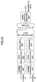
- FIG. 7 illustrating a portion of the transmitter 700, a common control channel processing unit 720, a shared control channel processing unit 740, a shared data channel processing unit 760, a radio resource assignment unit 702, an inverse Fourier transform unit 704 and a guard interval processing unit 706 are illustrated.
- the common control channel processing unit 720 conducts channel encoding, modulation and spreading for transmitting shared control channels.
- a shared control channel includes certain information such as a base station scramble code.
- the shared control channel processing unit 740 conducts encoding, modulation and spreading for transmitting shared control channels.
- a shared control channel includes certain information such as scheduling information for a mobile station to demodulate a shared data channel.
- the common control channel processing unit 720 includes a channel encoding unit 722, a data modulation unit 724 and a spreading unit 726. Also, the shared control channel processing unit 740 includes a channel encoding unit 742, a data modulation unit 744 and a spreading unit 746.
- the channel encoding units 722 and 742 encode incoming signals in accordance with a certain coding algorithm and supply the encoded signals.
- convolution coding may be conducted.
- the data modulation units 724 and 744 modulate incoming signals and supply the modulated signals.
- some modulation schemes such as QPSK may be carried out.
- the spreading units 726 and 746 spread incoming signals and supply the resulting signals.
- the shared data channel processing unit 760 conducts packet scheduling as well as channel encoding, modulation and spreading on shared data channels (transmitted data).
- the shared data channel processing unit 760 includes a packet scheduling unit 761, a data modulation unit 764 and a spreading unit 766.
- the packet scheduling unit 761 receives individual data items to be transmitted to one or more mobile stations, and schedules the data transmission based on feedback information and others supplied from the respective mobile stations.
- the data to be transmitted to the mobile stations are received from upper devices or networks other than a base station, and are separately stored in a transmission buffer (not shown) for the respective mobile stations.
- the feedback information includes a channel quality indicator (CQI) measured in each mobile station, and the CQI is represented as SIR in this embodiment.
- the packet scheduling unit 761 evaluates the channel condition for each mobile station based on the channel quality indicator CQI reported from the mobile station, and selects a mobile station (s) with a better channel condition. As stated below, the channel quality indicators CQIs supplied from mobile stations are reported for each frequency block (or chunk).
- the packet scheduling unit 761 determines a combination (MCS number) of a modulation scheme and a channel coding rate corresponding to downlink data transmission based on the channel quality indicators CQIs supplied from the respective mobile stations.
- the MCS number may be determined in accordance with a table as illustrated in FIG. 2 .
- the packet scheduling unit 761 conducts operations associated with packet retransmission based on the feedback information.
- Information items such as selected mobile stations, the MCS number and retransmission control information are supplied as control information to the shared control channel processing unit 740.
- Data to be transmitted to the selected mobile stations are supplied as transmitted data to the channel encoding unit 762.
- the channel encoding unit 762 encodes incoming signals in accordance with a certain coding algorithm, and supplies the encoded signals.
- turbo encoding may be carried out.
- the data modulation unit 764 modulates incoming signals and supplies the modulated signals.
- various types of modulation schemes such as QPSK, 16QAM and 64QAM may be used.
- the spreading unit 766 spreads incoming signals and supplies the spread signals.
- the radio resource assignment unit 702 multiplexes signals spread for a common control channel, a shared control channel and a shared data channel for output. This multiplexing may be carried out in accordance with any of time multiplexing, frequency multiplexing and code multiplexing and any combination thereof.
- FIG. 8 shows exemplary time multiplexing of two signals. In this illustration, "channel #1" and "channel #2" represent any two of a common control channel, a shared control channel and a shared data channel. Although multiplexing of two signals is illustrated therein for simplicity, three signals may be time multiplexed.
- FIG. 9 shows exemplary frequency multiplexing of two signals
- FIG. 10 shows exemplary code multiplexing of two signals.
- An appropriate radio resource (a time slot, a frequency band and/or a code) may be assigned to a common control channel, a shared control channel and a shared data channel through some multiplexing in the radio resource assignment unit 702 of FIG. 7 .
- the inverse Fourier transform unit 704 conducts inverse fast Fourier transform (IFFT) on incoming signals for modulation in accordance with the OFDM scheme, and supplies the modulated signals.
- IFFT inverse fast Fourier transform
- the guard interval processing unit 706 adds a guard interval to an incoming signal, and generates a symbol in compliance with the OFDM scheme (OFDM symbol) for output.
- the OFDM symbol is supplied to a radio unit (not shown) for radio transmission.
- FIG. 11 is a schematic diagram for explaining an exemplary operation of a transmitter according to one embodiment of the present invention.
- a wide downlink frequency band is divided into plural frequency blocks or chunks.
- each frequency block includes plural subcarriers.
- radio resources are assigned not only for each time slot (referred to as "transmission slot” in the illustration) but also for each frequency block.
- a time slot may consist of one transmission time interval (TTI) or any packet time duration.
- TTI transmission time interval
- the overall downlink frequency band is divided into eight frequency blocks where each of the frequency blocks includes the same number of subcarriers. For each of the eight frequency blocks, the channel condition is monitored, and the frequency block is assigned for a mobile station with a better channel condition.
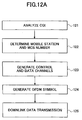
- FIG. 12A is a flowchart illustrating an exemplary transmission procedure in a base station.
- the base station receives channel quality indicators CQIs from one or more mobile stations, and analyzes the received channel quality indicators CQIs.
- the channel quality indicators CQIs such as reception SIRs are reported for each frequency block.
- the mobile stations measure quality of a received signal such as a pilot signal, and evaluate the downlink channel condition for each frequency block.
- step 122 it is determined which mobile station has a better channel condition for each frequency block based on the reception SIR reported for the frequency block, and a mobile station with the best reception SIR in the reported reception SIRs is selected for the frequency block.
- a combination (MCS number) of a modulation scheme and a channel coding rate corresponding to the reception SIR is determined. This determination of the combination may be made for each frequency block.
- a common control channel, a shared control channel and a shared data channel are generated. These generations are carried out in the respective processing units 720, 740 and 760 in FIG. 7 . Note that the respective channels do not have to be generated simultaneously in this step.
- the shared control channel is generated based on control information supplied from the packet scheduling unit 761 in FIG. 7 . This control information includes some information (MCS number etc.) required to demodulate the shared data channel. Specifications of the control information and transmission methods thereof will be described below.
- an OFDM symbol is generated. This generation is mainly carried out in the radio resource assignment unit 702, the IFFT unit 704 and the guard interval insertion unit 706.
- downlink data transmission is carried out in one or more frequency blocks in accordance with the determined MCS number.
- FIG. 12B is a flowchart for explaining exemplary detailed operations of the steps S123 and S124 in FIG. 12A .
- an error detection bit is added to a sequence of transmitted data.
- CRC cyclic redundancy check
- channel encoding is performed.
- the channel encoding is carried out in the channel encoding units 722, 742 and 762 in FIG. 7 , and particularly, the channel encoding for data channels is carried out in the channel encoding unit 762.
- step S3 some operation involved in hybrid ARQ is performed. More specifically, an information item is generated for indicating whether a transmitted packet is either a packet to be retransmitted or a new packet, and additionally, other information items may be generated for identifying the redundancy version of a retransmitted packet. This redundancy version can be modified through puncturing or repetition. Also, the channel coding rate may be modified at this step.
- step S4 in assignment to a physical channel, the encoded symbol is assigned for each frequency block. This assignment is mainly carried out in the radio resource assignment unit 702 in FIG. 7 . By frequency scheduling, it is determined for what frequency block the symbol of which user should be assigned.
- steps S5-1 to S5-N (N represents the total number of frequency blocks), in order to generate a transmission symbol, data modulation is performed for each frequency block. Subsequently, some operation (not shown) is carried out for radio transmission of the transmission symbol.
- one modulation scheme is determined for each frequency block, and different transmission rates suitable for the respective frequency blocks may be set.
- the illustrated operation is preferred from the viewpoint of improved transmission throughput.
- step S5' is uniformly carried out over some frequency blocks.
- a uniform modulation scheme is determined for all frequency blocks. More generally, such a uniform modulation scheme may be determined for plural frequency blocks. In the case where such a uniform modulation scheme is used for plural frequency blocks, it is possible to reduce the number of control bits (information amount) required to report the modulation scheme to the receiver side compared to the case of FIG. 12B .
- the modulation scheme may be determined for each frequency block.
- signal transmission may preferably be carried out in accordance with any of the schemes illustrated in FIGS. 12B and 12C in order to simplify the associated operation and encode data for different frequency blocks with the same accuracy.
- user #1 is selected for a certain transmission slot of frequency block #1 including the lowest subcarrier, and user #2 is selected for the next transmission slot.
- user #1 has the best channel condition in the first transmission slot of the frequency block and user #2 has the best channel condition in the next transmission slot.
- FIG. 13 shows primary items of control information supplied to the shared control channel processing unit 740 by the packet scheduling unit 761 in FIG. 7 in detail.
- the control information includes chunk allocation information, modulation scheme information, coding rate information, hybrid ARQ process information, redundancy version, packet status information and UE identity.
- the chunk allocation information specifies what frequency block is assigned for which mobile station (user).
- the number of frequency blocks assigned for a certain mobile station (user) may be determined depending on a requested data rate, and may be greater than or equal to 1 in general.
- user #1 is assigned to two frequency blocks #1 and #4 in the first transmission slot, and each of user #2 to user #6 and user #8 is assigned to one frequency block. In the subsequent transmission slot, each user is assigned to one frequency block.
- Such assignment to frequency blocks is described in the chunk allocation information.
- This information belongs to control information for the physical layer. Since it is described in this information how to allocate plural frequency blocks, the information does not have to be reported to the individual mobile stations for each frequency block.
- the modulation scheme information specifies modulation schemes for use in downlink data transmission, and is identified by the MCS number.
- various types of multilevel modulation schemes such as QPSK, 16QAM, 64QAM and 128QAM may be employed.
- This information belongs to control information for the physical layer. The information is preferably reported to mobile stations for each frequency block, but may be reported for plural frequency blocks.
- the channel coding rate may be managed for each modulation scheme as well as for each frequency block, and may be reported to mobile stations for each frequency block. On the other hand, the channel coding rate may be managed apart from the modulation scheme, and a uniform channel coding rate may be employed over plural frequency blocks. In FIG. 13 , "REQUIRED" of the rightmost column corresponds to the former case, whereas “NOT REQUIRED” corresponds to the latter case.
- the hybrid ARQ process information specifies a packet number associated with retransmission control. This information belongs to control information for the layer 2. A packet may be retransmitted for each frequency block in accordance with the hybrid ARQ. Alternatively, a packet may be retransmitted for each transmission slot without distinguishing between different frequency blocks.
- "REQUIRED" of the rightmost column corresponds to the former case, whereas "NOT REQUIRED” corresponds to the latter case.
- the redundancy version specifies what puncture pattern is used in retransmission control. This information belongs to control information for the layer 2. Similar to the hybrid ARQ process information, redundancy data may be transmitted for each frequency block. Alternatively, the redundancy data may be transmitted for each transmission slot without distinguishing between different frequency blocks. In FIG. 13 , "REQUIRED" of the rightmost column corresponds to the former case, whereas “NOT REQUIRED” corresponds to the latter case.
- the packet status information specifies whether a packet transmitted from a base station to a mobile station is a newly transmitted packet (new packet) or a retransmitted packet. This information belongs to control information for the layer 2.
- a packet may be retransmitted for each frequency block in accordance with the hybrid ARQ. Alternatively, it may be retransmitted for each transmission slot without distinguishing between different frequency blocks.
- "REQUIRED" of the rightmost column corresponds to the former case, whereas "NOT REQUIRED” corresponds to the latter case.
- the UE identity identifies which mobile station or user receives data transmitted in the downlink, and is also called a user identifier or identification information. This information belongs to control information for the physical layer. Similar to the chunk allocation information, the UE identity does not have to be reported to mobile stations for each frequency block.
- FIG. 14 shows exemplary mapping of a control channel and the other channels in downlink physical channels.
- the control channel is mapped or multiplexed in a certain frequency range over the entire time duration. The frequency range may or may not be the same as the frequency block range.
- the control channel is mapped in the overall frequency range in a certain time duration.
- the mappings of configurations 1 and 2 are combined.
- the control channel is mapped to certain frequency ranges over a certain time duration.
- frequency diversity has more advantage, which is desirable from the viewpoint of improvement of reception quality of signals.
- control channel is mapped to every frequency block in the downlink physical channel.
- the control channel may have a variable data size depending on the number of users or the number of frequency blocks. So, if all channels are mapped in accordance with the configuration 2, the control channel occupies variable duration, which may complicate demodulation.
- control channels associated with all frequency blocks are mapped to the entire frequency range as in the configuration 2, and thereby a control channel specific to a certain frequency block (specified control channel) only can be mapped to the frequency block. As a result, the efficiency and quality of demodulation of the control channels is improved.
- mapping configurations as illustrated in FIG. 14 are simply illustrative, and the control channel and the other channels may be multiplexed in various schemes including single time multiplexing, frequency multiplexing or code multiplexing or any combination thereof.
- the multiplexing is not limited to the control channel and the other channels, and may be performed on any channels.
- various modulation schemes may be employed. As one example, each of plural users may be assigned to one or more frequency blocks, and the modulation scheme may be determined in such a manner as illustrated in FIG. 12B . In the example illustrated in FIG. 15B , each of four users may be assigned to a frequency block, and different modulation schemes may be set for each of the frequency blocks.
- a uniform modulation scheme may be determined over plural frequency blocks as illustrated in FIG. 12C .
- the multiplexing in the frequency direction as illustrated in FIG. 15B is referred to as a localized frequency division multiplexing (localized FDM) scheme due to a certain band being occupied by a certain user.
- localized FDM localized frequency division multiplexing
- a scheme for distributing a channel associated with a certain user over a wideband is referred to as a distributed FDM scheme.
- each channel includes plural frequency components (subcarrier components) assigned in a uniform or non-uniform interval on the frequency axis, and different channels are made orthogonal with each other in the frequency range.
- channels of individual users are distributed over the whole system band, and are made orthogonal with each other in the frequency range.
- At least one of a modulation scheme and a channel coding rate may be determined for each frequency block or may be determined for plural frequency blocks uniformly. Also, they may be determined in further smaller frequency units.
- a modulation scheme may be determined for each subcarrier. Even if the modulation scheme is determined in such a smaller unit, however, it is estimated that the throughput cannot be so much improved. Also, since additional control channels for identifying all of them are required, there is a risk of increasing the processing workload and the amount of control information.
- the frequency diversity has more advantage, and thus improved signal quality can be expected. Therefore, in the case of the distributed FDM, it is desirable that the modulation scheme and the channel coding rate be uniformly determined over all subcarriers, resulting in a reduced amount of control information.
- FIG. 16 shows exemplary error detection encoding on a control channel.
- the error detection encoding may be carried out, for example, with the use of cyclic redundancy check CRC code.
- the error detection encoding makes it possible to prevent a user from demodulating data for another user and performing erroneous retransmission control, for example.
- control information for physical layer and control information for the upper layer 2 are separately error detection encoded. It is advantageous in terms of mapping per frequency block like the configuration 4 in FIG. 14 to conduct error detection encoding depending on the type of the control information.
- control information for the physical layer and the control information for the upper layer 2 may be error detection encoded together. Compared to the case where the error detection encodings are separately carried out, this scheme is advantageous due to reduced overhead.
- they are error detection encoded separately to improve error detection capability and fulfill a smaller retransmission unit as illustrated in FIG. 16A .
- FIG. 17 shows exemplary error correction encoding on control information.
- the error correction encoding may be carried, for example, by use of convolution encoding.
- the error correction encoding may improve tolerance over multipath fading, for example.
- the control information for the physical layer and the control information for the upper layer 2 are error correction encoded separately.
- the control information for the physical layer and the control information for the upper layer 2 are error correction encoded together.
- error correction encoding is performed on the overall control information. This is desirable from the viewpoint of reduced overhead.
- the error correction capability is advantageous to the case (B) of a longer coding unit.
- such a longer coding unit may cause chaining of a bit error to subsequent bits.
- the longer coding unit may tend to increase the error occurrence probability.
- the coding unit may be determined by balancing these characteristics.
- FIG. 18 shows an exemplary table for listing various methods where one or more of frequency range based packet scheduling, adaptive modulation coding (AMC) and hybrid ARQ are carried out for each frequency block. In one row, some features of one method are illustrated.
- AMC adaptive modulation coding
- the symbol double circle “ ⁇ ” indicates that the data transmission is extremely efficient.
- the symbol circle “ ⁇ ” indicates that the data transmission is very efficient.
- the symbol triangle “ ⁇ ” indicates that the data transmission is moderately efficient.
- the symbol cross “ ⁇ ” indicates that the data transmission is inefficient.
- the symbol double circle “ ⁇ ” indicates that the overhead is very low.
- the symbol circle “ ⁇ ” indicates that the overhead is low.
- the symbol triangle “ ⁇ ” indicates that the overhead is high.
- the symbol cross “ ⁇ ” indicates that the overhead is very high. Note that the symbols used herein simply indicate tendency of relative merits and the availability is not necessarily determined.
- the frequency range based packet scheduling, the data modulation and the hybrid ARQ are controlled for each frequency block, whereas the channel coding rate is controlled for each transmission time interval TTI.
- the transmission time interval is a constant unit time specific to a system.
- only the channel coding rate is set to have a uniform value over all frequency blocks.
- the method 2 achieves reduction in overhead compared to the method 1 in that the channel coding rate does not have to be managed for each frequency block.
- the modulation scheme information, the hybrid ARQ process information, the redundancy version and the packet status information are reported to mobile stations for each frequency block, whereas a uniform coding rate information over all frequency blocks is reported.
- the frequency range based packet scheduling, the data modulation and the hybrid ARQ are controlled for each frequency block, whereas the channel coding rate is controlled for each packet.
- the length (duration) of a packet may be a relative amount defined in an upper network, for example, it may or may not be the same as absolute unit time (TTI) specific to a system.
- TTI absolute unit time
- only the channel coding rate is set to have a uniform value over all frequency blocks.
- the method 3 can also reduce the overhead compared to the method 1 in that the channel coding rate does not have to be managed for each frequency block.
- the modulation scheme information, the hybrid ARQ process information, the redundancy version and the packet status information are reported to mobile stations for each frequency block, whereas uniform coding rate information over all frequency blocks is reported. Note that the coding rate information has to be reported for each packet.
- the frequency range based packet scheduling, the data modulation and the channel encoding are controlled for each frequency block, whereas the hybrid ARQ is controlled for each packet.
- retransmission is controlled without distinguishing between different frequency blocks, resulting in reduced overhead accordingly.
- the length of a packet is equal to one unit of actually communicated information, and retransmission is carried out for each packet. This is preferable from the viewpoint of improvement of the throughput. More specifically, the modulation scheme information and the coding rate information are reported to mobile stations for each frequency block, whereas the hybrid ARQ process information, the redundancy version and the packet status information are reported uniformly over all frequency blocks. Note that information associated with retransmission control has to be reported for each packet.
- the frequency range based packet scheduling and the data modulation are controlled for each frequency block, the channel coding is controlled for each transmission time interval, and the hybrid ARQ is controlled for each packet.
- the channel coding rate and retransmission are controlled without distinguishing between different frequency blocks, resulting in reduced overhead accordingly.
- the modulation scheme information is reported to mobile stations for each frequency block, whereas the coding rate information, the hybrid ARQ process information, the redundancy version and the packet status information are reported uniformly over all frequency blocks. Note that information associated with retransmission control has to be reported for each packet.
- the frequency range based packet scheduling and the data modulation are controlled for each frequency block, whereas the channel coding rate and the hybrid ARQ are controlled for each packet.
- the channel coding rate and retransmission are controlled without distinguishing between different frequency blocks, resulting in reduced overhead accordingly.
- the modulation scheme information is reported to mobile stations for each frequency block, whereas the coding rate information, the hybrid ARQ process information, the redundancy version and the packet status information are reported uniformly over all frequency blocks. Note that some information associated with the coding rate and the retransmission control has to be reported for each packet.
- the frequency range based packet scheduling, the data modulation and the channel coding are controlled for each frequency block, whereas the hybrid ARQ is controlled for each transmission time interval TTI.
- the method 7 can reduce overhead in that the retransmission does not have to be controlled for each frequency block.
- the retransmission control can be simplified. More specifically, the modulation scheme information and the coding rate information are reported to mobile stations for each frequency block, whereas the hybrid ARQ process information, the redundancy version and the packet status information are reported uniformly over all frequency blocks. Note that some information associated with the retransmission control has to be reported for each transmission time interval TTI.
- the frequency range based packet scheduling and the data modulation are controlled for each frequency block, whereas the channel coding and the hybrid ARQ are controlled for each transmission time interval.
- the channel coding rate and the retransmission are controlled without distinguishing between different frequency blocks, resulting in reduced overhead accordingly.
- the modulation scheme information is reported to mobile stations for each frequency block, whereas the coding rate information, the hybrid ARQ process information, the redundancy version and the packet status information are reported uniformly over all frequency blocks. Note that some information associated with the coding rate information and the retransmission control has to be reported for each transmission time interval.
- the frequency range based packet scheduling and the data modulation are controlled for each frequency block, the channel coding is controlled for each packet, and the hybrid ARQ is controlled for each transmission time interval.
- the channel coding rate and the retransmission control are controlled without distinguishing between different frequency blocks, resulting in reduced overhead accordingly.
- the modulation scheme information is reported to mobile stations for each frequency block, whereas the coding rate information, the hybrid ARQ process information, the redundancy version and the packet status information are reported uniformly over all frequency blocks. Note that the coding rate information has to be reported for each packet and that some information associated with the retransmission control has to be reported for each transmission time interval.
- the frequency range based packet scheduling is controlled for each frequency block, whereas the data modulation, the channel coding and the hybrid ARQ are controlled for each transmission time interval.
- the data modulation, the channel coding rate and the retransmission are controlled without distinguishing between different frequency blocks, resulting in extremely reduced overhead.
- the modulation scheme information, the coding rate information, the hybrid ARQ process information, the redundancy version and the packet status information are reported uniformly over frequency blocks. Note that these information items have to be reported for each transmission time interval TTI.
- the channel coding rate is desirably controlled for each transmission time interval TTI from the viewpoint of simplified retransmission control.
- attachment of CRC bits, the channel coding and the retransmission control are carried out for only a single data sequence.
- the attachment of CRC bits, the channel coding and the retransmission control are carried out for each of plural data sequences.
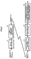
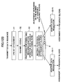
- FIG. 20 is a flowchart (1) illustrating an exemplary transmission procedure according to one embodiment of the present invention.
- a sequence of transmitted data is divided into plural sequences.
- the operation on the divided sequences is performed as in the flowchart (1) in FIG. 12B .
- the division of the data sequence may be carried out, for example, in a serial to parallel (S/P) conversion unit.
- the division may be referred to as partition and segmentation.
- the size of divided data may be the minimum unit for retransmission. It is desirable that the size of divided data be made smaller from the viewpoint of retransmission of minimum required information. On the other hand, it is desirable that the size of divided data be made larger from the viewpoint of reduction in overhead associated with the retransmission.
- the division can be triggered.
- the transmitted data sequence is divided into two sequences for simplicity, the transmitted data sequence may be divided into more than two sequences. Also, in the case where the division is triggered by the data size exceeding a threshold, the two lines of flow in FIG. 20 may not be necessarily conducted simultaneously. (If the data size is small, only one of the left-hand flow and the right-hand flow may be conducted.)
- an error detection bit is attached to each of the divided transmitted data sequences.
- the data size of the divided sequences may or may not be uniform over the sequences.
- each of the divided transmission data sequences is channel encoded.
- the channel coding rate R1 for step S13 and the channel coding rate for step S23 maybe determined independently. Also, they may be set to be different values or the same value.
- an operation associated with hybrid ARQ is performed on each of the divided transmitted data sequences. More specifically, some information is generated for indicating whether a packet to be transmitted is a retransmitted packet or a new packet. In addition, some information may be generated for indicating the redundancy version of the transmitted packet and others.
- the redundancy version for step S14 and the redundancy version for step S24 may be determined independently. Also, they may be set to be different versions or the same version.
- a physical channel is assigned to each of the divided transmitted data sequences, and an encoded symbol is assigned to each frequency block. This operation is mainly conducted in the radio resource assignment unit 702. It is determined in frequency scheduling which frequency block is assigned to the symbol of which user.
- steps S16-1 to S16-K and S26-1 to S26-L data modulation is carried out for each frequency block for generating a transmission symbol.
- K and L represent the total number of frequency blocks in the respective sequences. Subsequently, some operation (not shown) is conducted for radio transmission of the transmission symbol.
- the transmission rate is set to have a value suitable for each frequency block.
- the illustrated exemplary operation is preferable from the viewpoint of improved transmission throughput.
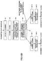
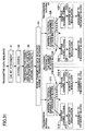
- FIG. 21 is a flowchart (1)' illustrating an exemplary transmission procedure. This flowchart is the same as FIG. 20 except for step 3.
- FIG. 22 is another flowchart (2) illustrating a transmission procedure.
- the operation subsequent to division at step S1 is the same as the flowchart (2) in FIG. 12C .
- This flow is the same as the flow in FIG. 20 except for steps S16' and S26'.
- modulation schemes are determined for two divided sequences of transmitted data independently, but the same modulation scheme is applied to the same data sequence.
- different modulation schemes may be applied to different frequency blocks. Since the same modulation scheme is applied to plural frequency blocks, it is possible to reduce the number of control bits required to report the modulation scheme to the receiver side.
- FIG. 23 is a flowchart (2)' illustrating an exemplary transmission procedure. This flow is the same as the flow in FIG. 22 except for step S3.
- the same modulation scheme is applied to the same data sequence. Since the same channel coding rate is applied to the different sequences and the same modulation scheme is applied to plural frequency blocks, it is possible to reduce the number of control bits required to report the channel coding rate and the modulation scheme to the receiver side.
- FIG. 24 is another flowchart (2)" illustrating an exemplary transmission procedure. This flow is the same as the flow in FIG. 23 except for step S6.
- the same modulation scheme is applied to the data sequences. Since the same channel coding rate is applied to different sequences and the same modulation scheme is applied to all frequency blocks, it is possible to further reduce the number of control bits required to report the channel coding rate and the modulation scheme.
- FIG. 25 is another flowchart (3) illustrating an exemplary transmission procedure.
- the operation subsequent to the division at step S1 is the same as the flowchart (3) in FIG. 12D .
- this flow is the same as the flow in FIG. 20 except for steps S13-1 to S13-K and S23-1 to S23-L.
- channel coding may be performed on each frequency block.
- the division of a data sequence to be transmitted into plural sequences may be conducted by means of various products and applications under various processing environments.
- the data sequence to be transmitted is divided corresponding to plural reception antennas.
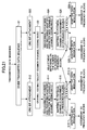
- FIG. 26 is a flowchart (1) illustrating an exemplary transmission procedure according to the third embodiment.
- a data sequence is finally transmitted from a single transmission antenna.
- divided data sequences are transmitted from different transmission antennas #1 and #2. Similar to the case of FIG. 20 , the number of divided sequences may be set to be an arbitrary value, that is, any number of transmission antennas may be provided.
- the operation associated with a single transmission antenna (for example, transmission antenna #1) in FIG. 26 may be replaced with any of the operations described in conjunction with FIGS. 20-25 .
- a data sequence transmitted from a single transmission antenna may be divided into plural data sequences.
- such a data sequence to be transmitted is divided into a larger number of data sequences than the number of transmission antennas.
- a channel coding rate is set for each of the transmission antennas and a modulation scheme is set for each frequency block. This procedure is preferred from the viewpoint of improved throughput.
- FIG. 27 is another flowchart (2) illustrating an exemplary transmission procedure. This flow is the same as the flow in FIG. 22 except that divided different data sequences are transmitted from the different transmission antennas #1 and #2.
- the same modulation scheme is applied to plural frequency blocks (all frequency blocks in the illustration).
- it is possible to reduce the number of control bits required to report the modulation scheme to the receiver side. Since this reducing advantage grows proportionately to the number of transmission antennas, the number of control bits may be further significantly reduced compared to the second embodiment.
- FIG. 28 is another flowchart (3) illustrating an exemplary transmission procedure. This flow is the same as the flow in FIG. 25 except that divided different data sequences are transmitted from different transmission antennas #1 and #2.
- the fourth embodiment of the present invention also relates to the multi-antennas scheme.
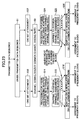
- FIG. 29 is a flowchart (1) illustrating an exemplary transmission procedure. The individual steps have been already explained in detail, and thus the duplicative description thereof will be omitted.
- attachment of a CRC bit, channel coding and retransmission control are carried out uniformly over the all the transmission antennas.
- the attachment of a CRC bit and the channel coding are performed on a packet with a relatively large data size.
- this packet is divided and transmitted via the transmission antennas. According to this embodiment, it is possible to reduce the number of control bits required to report the channel coding rate to the receiver side and provide the CRC bit.
- FIG. 30 is a flowchart (2) illustrating an exemplary transmission procedure.
- the attachment of a CRC bit, the channel coding and the retransmission control are carried out uniformly over all transmission antennas as in FIG. 29 .
- the same modulation scheme is applied to data transmitted from the same transmission antenna regardless of frequency blocks. Since the same modulation scheme is applied to plural frequency blocks, it is possible to reduce the number of control bits required to report the modulation scheme to the receiver side.
- FIG. 31 is a flowchart (3) illustrating an exemplary transmission procedure.
- the attachment of CRC bits, the channel coding and the retransmission control are carried out uniformly over all transmission antennas as in FIG. 29 .
- the modulation scheme is not only determined for each frequency block but also the channel coding rate is determined for each frequency block.
- adaptive modulation coding is controlled in transmission of shared data channels.
- transmission power is kept constant under the AMC control. That is intended to maintain signal quality by communicating under a combination (MCS) of a modulation scheme and a coding scheme suitable for the channel condition.
- MCS combination
- the fifth embodiment of the present invention can address the above-mentioned problem.
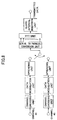
- FIG. 32 is a block diagram illustrating a transmitter according to this embodiment.
- This transmitter is the same as the transmitter described above in conjunction with FIG. 7 except that a shared data channel processing unit 760 in FIG. 32 includes a power control unit 768.
- some components for setting transmission power for common control channels and shared control channels may be provided, these components do not relate to the present invention directly and thus are not illustrated.
- the channel coding rate, the modulation scheme and the transmission power are kept constant for the common control channels.
- the channel coding rate, the modulation scheme and the transmission power are kept constant in general.
- the transmission power for the shared control channels may be controlled in accordance with open-loop or closed-loop transmission power control or based on reception quality (CQI information) of downlink pilot channels reported from mobile stations.
- CQI information reception quality
- the power control unit 768 adjusts the transmission power for data channels based on power control information supplied from the packet scheduling unit 761.
- the power control information includes information for specifying transmission power of shared data channels for each resource block (frequency block).
- the power control information is determined by the packet scheduling unit 761.
- the power control information may be derived based on a correspondence predetermined between modulation schemes (or MCSs) and transmission power levels. Alternatively, the power control information may be found without use of such a predetermined correspondence.
- the power control information may be updated for each subframe (or TTI) or may be more or less frequently updated.
- FIG. 33 shows an exemplary correspondence available to the case where the power control information is derived bases on a predefined correspondence.
- the transmission power P1 is used in case of the modulation scheme being QPSK.
- the transmission power P2 is used in case of the modulation scheme being 16QAM.
- the transmission power P3 is used in case of the modulation scheme being 64QAM.
- the data modulation schemes and/or the transmission power levels are not limited to the above three types, and may have more or less types.
- the modulation scheme and the transmission power may or may not have one-on-one correspondence to each other.
- the same transmission power P1 may be used for both QPSK and 16QAM.
- FIG. 34 shows an exemplary correspondence between MCSs and transmission power levels. The correspondence is not limited to the illustrations in FIGS. 33 and 34 , and any other correspondence may be predefined. It is sufficient that the transmission power can be derived from the modulation schemes and others.
- FIGS. 35A and 35B show exemplary transmission power for individual resource blocks.
- the same transmission power level is set for all resource blocks, which corresponds to case of transmission power under the conventional AMC control.
- FIG. 35B illustrates an exemplary case where the AMC control as well as the transmission power level is set for each resource block. Since not only MCSs but also the transmission power can be adaptively changed, the throughput can be further improved compared to the case with use of only the AMC control.
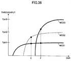
- FIG. 36 schematically shows an exemplary relationship between throughputs achievable under predefined MCSs and signal-to-noise ratios (SNRs).
- MCS1 has a lower bit rate than MCS2 and in turn MCS2 has a lower bit rate than MCS3.
- the maximum throughputs achievable under MCS1, MCS2 and MCS3 be Tph1, Tph2 and Tph2, respectively.
- the SNR under a certain transmission power level is equal to the value "E" in the illustration.
- the throughput achievable under MCS1 is approximately Tph1, whereas throughput higher than Tph1 may be achievable under MCS2.
- MCS2 is not provided in the system and only the MCS1 and MCS3 are pprovided in the system.
- the conventional AMC control when the SNR is equal to E, only MCS1 can be adopted in the system.
- higher transmission power is achieved. For example, it is possible to increase the SNR from E to F. Once the SNR is equal to F, MCS3 together with MCS1 become available. By using MCS3, higher throughput is achieved.
- MCS1 and MCS3 are provided in a system among the three types of MCSs, that is, MCS1, MCS2 and MCS3, higher throughput is achieved. In other words, it is possible to use variable transmission power to reduce the kinds of MCSs while maintaining high throughput.
- the level of transmission power may be derived based on a predefined correspondence between modulation schemes or others and transmission power levels. Alternatively, it may be found without use of such a predefined correspondence.
- power information indicative of the predefined correspondence is stored as common information between a base station and a mobile station in respective memories.
- the mobile station can determine The transmission power for an MCS reported from the base station with reference to the correspondence. In this case, the base station does not have to transmit the information indicative of the transmission power via shared control channels or others.
- the predefined correspondence may be reported to the mobile station via a common control channel such as broadcast information. Alternatively, the correspondence may be reported to the mobile station as layer 3 information at call setting time or may be written in ROM as system specific information.
- the base station may derive the transmission power individually so to as facilitate the best throughput. Since the MCS as well as the transmission power is optimized, this method is particularly advantageous to improve achievable throughput. Note that information for indicating which resource block has been used for transmission via a data channel at what level of the transmission power has to be reported to mobile stations via shared control channels.
- the base station does not have to report the transmission power to mobile stations via shared control channels.
- the mobile stations may measure reception quality of individual resource blocks assigned for themselves, and may estimate the transmission power.
- the frequency of how often assignment status of resource blocks (information indicating which resource blocks are assigned for which users) is reported to mobile stations may be reported for each subframe (TTI) or less frequently. More generally, the respective frequency of reporting to mobile stations may or may not be the same for all or a portion of the resource block assignment status, the MCS number and the transmission power.
- a shared control channel may be used for the reporting.
- FIG. 37 schematically shows an exemplary assignment of resource blocks.
- shaded resource areas are assigned for certain users.
- assignment status of resource blocks is reported to mobile stations every three subframes (resource assignment report), and the assignment is modified if needed.
- the resource block assignment status is invariantly maintained during the three subframes.
- a resource block is assigned for a user with a better channel condition, there is no guarantee that the good channel condition is maintained throughout all resource blocks during the three subframes. In some cases, the channel condition may change into a worse condition.
- " ⁇ " marked resource blocks indicate that their channel condition has become worse. The " ⁇ " marked resource blocks should not be used as data channels for transmission.
- the transmission power for these resource blocks may be set to be zero to prevent the resource blocks from being used.
- unnecessary data transmission can be avoided by setting the transmission power for resource blocks with poor channel condition to be zero.
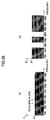
- FIG. 38A schematically shows an exemplary case where some data are transmitted at the same transmission power in all the eight resource blocks assigned for certain users. This corresponds to the case of the conventional AMC control and is the same as FIG. 35A .
- FIG. 38B shows an exemplary case where the transmission power for recourse blocks RB3 and RB5 is set to be zero. In this case, it is desirable that a base station raise the transmission power associated with resource blocks other than the resource blocks RB3 and RB5 as well as keep the total amount of transmission power as constant as possible.
- FIGS. 39A and 39B show respective cases before and after the transmission power for the resource blocks RB3 and RB5 being set to zero. In the illustration, the transmission power is controlled as in the case of FIG. 35B . As illustrated in FIG. 39B , the transmission power is raised for each resource block.
- Information indicating for which resource block the transmission power is set to be zero may be reported to mobile stations via any shared control channels other than shared control channels indicative of resource block assignment status. However, it is likely that such shared control channels are not necessarily provided. For example, mobile stations may intend to receive all the resource blocks assigned for themselves, and may ignore signals for resource blocks with less than a predefined reception quality (in the above example, RB3 and RB5). When the information indicating for which resource block the transmission power is equal to zero is reported to a mobile station, the mobile station can measure reception quality associated with each resource block with high accuracy based on the reported information, the total transmission power and reception power for the mobile station.
- a predefined reception quality in the above example, RB3 and RB5
Landscapes
- Engineering & Computer Science (AREA)
- Signal Processing (AREA)
- Computer Networks & Wireless Communication (AREA)
- Quality & Reliability (AREA)
- Mobile Radio Communication Systems (AREA)
- Transmitters (AREA)
Applications Claiming Priority (4)
| Application Number | Priority Date | Filing Date | Title |
|---|---|---|---|
| JP2005106908 | 2005-04-01 | ||
| JP2006009299 | 2006-01-17 | ||
| JP2006031750A JP2007221178A (ja) | 2005-04-01 | 2006-02-08 | 送信装置及び送信方法 |
| EP20060729467 EP1871028A4 (fr) | 2005-04-01 | 2006-03-20 | Appareil de transmission et méthode de transmission |
Related Parent Applications (1)
| Application Number | Title | Priority Date | Filing Date |
|---|---|---|---|
| EP20060729467 Division EP1871028A4 (fr) | 2005-04-01 | 2006-03-20 | Appareil de transmission et méthode de transmission |
Publications (2)
| Publication Number | Publication Date |
|---|---|
| EP3076573A2 true EP3076573A2 (fr) | 2016-10-05 |
| EP3076573A3 EP3076573A3 (fr) | 2016-12-21 |
Family
ID=37086727
Family Applications (2)
| Application Number | Title | Priority Date | Filing Date |
|---|---|---|---|
| EP16158675.5A Ceased EP3076573A3 (fr) | 2005-04-01 | 2006-03-20 | Appareil de transmission et procédé de transmission |
| EP20060729467 Withdrawn EP1871028A4 (fr) | 2005-04-01 | 2006-03-20 | Appareil de transmission et méthode de transmission |
Family Applications After (1)
| Application Number | Title | Priority Date | Filing Date |
|---|---|---|---|
| EP20060729467 Withdrawn EP1871028A4 (fr) | 2005-04-01 | 2006-03-20 | Appareil de transmission et méthode de transmission |
Country Status (11)
| Country | Link |
|---|---|
| US (3) | US8208363B2 (fr) |
| EP (2) | EP3076573A3 (fr) |
| JP (1) | JP2007221178A (fr) |
| KR (1) | KR101222998B1 (fr) |
| CN (2) | CN102098134B (fr) |
| AU (1) | AU2006234022B8 (fr) |
| BR (1) | BRPI0606467A2 (fr) |
| CA (1) | CA2602734C (fr) |
| SG (1) | SG155249A1 (fr) |
| TW (1) | TW200705867A (fr) |
| WO (1) | WO2006109436A1 (fr) |
Families Citing this family (65)
| Publication number | Priority date | Publication date | Assignee | Title |
|---|---|---|---|---|
| JP2007221178A (ja) | 2005-04-01 | 2007-08-30 | Ntt Docomo Inc | 送信装置及び送信方法 |
| RU2408987C2 (ru) * | 2005-04-01 | 2011-01-10 | Нтт Досомо, Инк. | Передающее устройство и способ передачи сигнала |
| JP4671771B2 (ja) * | 2005-06-10 | 2011-04-20 | 株式会社エヌ・ティ・ティ・ドコモ | 無線通信装置及び無線通信方法 |
| US20070036067A1 (en) * | 2005-08-12 | 2007-02-15 | Interdigital Technology Corporation | Method and apparatus for sending downlink control information in an orthogonal frequency division multiple access system |
| KR100984819B1 (ko) * | 2005-10-07 | 2010-10-04 | 인터디지탈 테크날러지 코포레이션 | 고속 다운링크 및 업링크를 지원하기 위한 제어 정보의제공 방법 및 시스템 |
| WO2007083728A1 (fr) * | 2006-01-23 | 2007-07-26 | Sharp Kabushiki Kaisha | Dispositif de station de base, dispositif de station mobile, procédé d'attribution d'identificateur de station mobile ainsi que programme et support d'enregistrement associés |
| JP5106796B2 (ja) * | 2006-06-19 | 2012-12-26 | 株式会社エヌ・ティ・ティ・ドコモ | 基地局、送信方法 |
| DK2381728T3 (da) * | 2006-08-21 | 2013-10-07 | Interdigital Tech Corp | Planlægning og signalering af dynamisk ressourceallokering for en variabel datahastighedstjeneste i LTE |
| US7839835B2 (en) * | 2006-08-22 | 2010-11-23 | Nec Laboratories America, Inc. | Quantized precoding over a set of parallel channels |
| CA2878737C (fr) | 2006-10-03 | 2018-10-02 | Interdigital Technology Corporation | Commande de puissance d'emission amont (a cqi) a boucle ouverte et a boucle fermee combinee avec attenuation d'interference pour e-utra |
| EP2077634B1 (fr) * | 2006-10-26 | 2016-02-24 | Fujitsu Limited | Appareil de station radio fixe, procédé de transmission de pilotes et appareil terminal |
| US20080159253A1 (en) * | 2006-12-29 | 2008-07-03 | Motorola, Inc. | Method to increase link quality in multihop system |
| EP2104370B1 (fr) | 2007-01-09 | 2020-08-12 | Sun Patent Trust | Dispositif de station de base pour communications radio et procédé de mise en correspondance de signaux de commande |
| US8249634B2 (en) | 2007-01-12 | 2012-08-21 | Ntt Docomo, Inc. | Base station apparatus and communications control method |
| EP2107700A4 (fr) * | 2007-01-26 | 2013-06-19 | Nec Corp | Système de communication mobile, terminal, dispositif de station de base, et procédé de communication de données |
| KR101341493B1 (ko) | 2007-01-30 | 2013-12-16 | 엘지전자 주식회사 | 채널 환경에 따른 mcs 인덱스 선택 방법, 자원 할당방식 선택 방법 및 이를 위한 송신기 |
| KR101397135B1 (ko) | 2007-03-07 | 2014-05-22 | 인터디지탈 테크날러지 코포레이션 | 이동국의 업링크 전력을 제어하기 위한 결합형 개방 루프/폐쇄 루프 방법 |
| JP4913641B2 (ja) * | 2007-03-20 | 2012-04-11 | 株式会社エヌ・ティ・ティ・ドコモ | 基地局、通信端末、送信方法、受信方法、通信システム |
| CA2680403C (fr) | 2007-03-23 | 2021-03-30 | Panasonic Corporation | Dispositif de station de base de radiocommunication et procede d'agencement de canal de commande |
| RU2458483C2 (ru) * | 2007-03-23 | 2012-08-10 | Панасоник Корпорэйшн | Устройство базовой станции радиосвязи и способ отображения каналов управления |
| US20080259802A1 (en) * | 2007-04-19 | 2008-10-23 | Nokia Corporation | Frequency domain packet scheduling under fractional load |
| US20080305824A1 (en) * | 2007-04-20 | 2008-12-11 | Interdigital Technology Corporation | Apparatus and method for computing maximum power reduction for a umts signal |
| DE602008017325C5 (de) | 2007-06-08 | 2022-05-12 | MiiCs & Partners Japan Co., Ltd. | Mobiles Kommunikationssystem, Basisstationsvorrichtung und Mobilstationsvorrichtung |
| US8446849B2 (en) | 2007-06-20 | 2013-05-21 | Qualcomm Incorporated | Methods and apparatuses for power control |
| US8125884B1 (en) | 2007-07-11 | 2012-02-28 | Marvell International Ltd. | Apparatus for pre-coding using multiple codebooks and associated methods |
| BRPI0721907A2 (pt) | 2007-08-10 | 2014-02-25 | Fujitsu Ltd | Estação base de rádio e estação móvel. |
| CN103763069B (zh) * | 2007-08-10 | 2017-04-26 | 富士通株式会社 | 移动台以及无线基站 |
| CN103763075B (zh) * | 2007-08-10 | 2017-02-08 | 富士通株式会社 | 无线通信系统以及无线通信方法 |
| DK2141846T3 (da) | 2007-09-06 | 2013-03-11 | Sharp Kk | Kommunikationsapparat og kommunikationsfremgangsmåde |
| JP5170533B2 (ja) * | 2008-01-24 | 2013-03-27 | 日本電気株式会社 | 無線伝送装置、変調方式決定方法及びそのプログラム |
| JP5063387B2 (ja) | 2008-01-28 | 2012-10-31 | 京セラ株式会社 | 無線通信システム、送信装置、受信装置、無線通信方法 |
| CN104253670B (zh) * | 2008-02-12 | 2018-04-10 | 艾利森电话股份有限公司 | 无线通信网络中的方法和装置 |
| EP2254366B1 (fr) * | 2008-03-12 | 2019-02-27 | Panasonic Intellectual Property Corporation of America | Dispositif de radiocommunication, système de radiocommunication et procédé de radiocommunication |
| JP2009296325A (ja) | 2008-06-05 | 2009-12-17 | Fujitsu Ltd | 無線通信装置、通信システム及び周波数リソース割当方法 |
| JP2010011174A (ja) * | 2008-06-27 | 2010-01-14 | Kyocera Corp | 無線通信方法、無線通信システム及び無線通信装置 |
| BRPI0921477B1 (pt) * | 2008-10-31 | 2020-10-27 | Godo Kaisha Ip Bridge 1 | aparelho de estação base, método de comunicação, aparelho terminal e método de comunicação para um aparelho de terminal |
| JP5461824B2 (ja) * | 2008-11-04 | 2014-04-02 | 株式会社Nttドコモ | 基地局装置、移動端末装置、移動通信システム及び情報再送方法 |
| WO2010073290A1 (fr) * | 2008-12-22 | 2010-07-01 | Nec Corporation | Système de communication, équipement d'utilisateur, station de base, procédé de décision de puissance de transmission et programme |
| US8380135B2 (en) * | 2009-05-04 | 2013-02-19 | Lg Electronics Inc. | Method of transmitting control information in wireless communication system |
| PL3179769T3 (pl) * | 2009-10-02 | 2019-03-29 | Sun Patent Trust | Stacja bazowa i sposób sterowania ponownym przesyłaniem |
| WO2011039575A1 (fr) * | 2009-10-02 | 2011-04-07 | Nokia Siemens Networks Oy | Allocation dynamique pour canal de commande et canal de données dans une sous-trame |
| KR101148727B1 (ko) * | 2009-12-15 | 2012-05-21 | 한국전자통신연구원 | 제어 정보를 기지국으로 전송하는 데이터 전송 시스템 |
| JP5532055B2 (ja) | 2009-12-24 | 2014-06-25 | 日本電気株式会社 | 無線通信装置、無線通信システムおよび無線通信方法 |
| US8660072B2 (en) * | 2010-01-18 | 2014-02-25 | Telefonaktiebolaget L M Ericsson (Publ) | Methods and apparatus for improved reference signal correlation characteristics |
| JP5704160B2 (ja) * | 2010-02-23 | 2015-04-22 | 日本電気株式会社 | 無線基地局およびその適応変調制御方法 |
| CN102299761B (zh) * | 2010-06-25 | 2016-04-13 | 中兴通讯股份有限公司 | 用于多天线技术的amc调整方法和基站 |
| JP5427139B2 (ja) * | 2010-07-29 | 2014-02-26 | 株式会社日立製作所 | 基地局及びセルラ無線通信システム |
| WO2012042748A1 (fr) * | 2010-09-30 | 2012-04-05 | パナソニック株式会社 | Dispositif de communication sans fil |
| EP2628280B1 (fr) * | 2010-10-13 | 2018-05-16 | Samsung Electronics Co., Ltd | Procédé et appareil pour multiplexer des données de communication concernant le type de machine pour de multiples dispositifs mtc dans un environnement de réseau sans fil |
| JP5514324B2 (ja) * | 2010-11-02 | 2014-06-04 | パナソニック株式会社 | 通信システム |
| CN102572927B (zh) * | 2010-12-30 | 2014-10-08 | 中国移动通信集团设计院有限公司 | 一种基站功率分配的方法、装置及系统 |
| JP2013038585A (ja) * | 2011-08-08 | 2013-02-21 | Sony Corp | 無線基地局、送信電力制御方法及びコンピュータプログラム |
| US20130301587A1 (en) * | 2011-11-02 | 2013-11-14 | Qualcomm Incorporated | Blindly decoding interfering cell pdcch to acquire interfering cell pdsch transmission information |
| CN113364556A (zh) | 2012-03-02 | 2021-09-07 | 华为技术有限公司 | 信息传输方法和设备 |
| JP5774526B2 (ja) * | 2012-03-14 | 2015-09-09 | Kddi株式会社 | 光直交周波数多重伝送方式による光伝送装置および方法 |
| US10098095B2 (en) * | 2012-05-25 | 2018-10-09 | Qualcomm Incorporated | Feedback to enhance rate prediction with bursty interference |
| JP2012227963A (ja) * | 2012-08-06 | 2012-11-15 | Fujitsu Ltd | 無線基地局および移動局 |
| US9955387B1 (en) * | 2013-05-16 | 2018-04-24 | Sprint Spectrum L.P. | Management of modulation for transmission of data in anticipation of handover |
| US10075954B2 (en) * | 2013-09-20 | 2018-09-11 | Blackberry Limited | Systems and methods for band-limited subframes in wireless networks |
| CN105245308B (zh) * | 2014-06-18 | 2018-09-28 | 国家新闻出版广电总局广播科学研究院 | 自适应调制编码方法 |
| WO2016066280A1 (fr) * | 2014-10-30 | 2016-05-06 | Telefonaktiebolaget L M Ericsson (Publ) | Planification sélective de fréquences |
| CN109906571B (zh) * | 2016-11-04 | 2021-11-05 | 北京易通峰联信息技术有限公司 | 数据传输方法及装置 |
| JP7076018B1 (ja) | 2021-02-01 | 2022-05-26 | Nttエレクトロニクス株式会社 | 誤り訂正システム、誤り訂正方法、および通信システム |
| WO2022264320A1 (fr) * | 2021-06-16 | 2022-12-22 | 日本電信電話株式会社 | Système de communication sans fil, procédé de communication sans fil, dispositif de contrôle de communication sans fil et programme |
| CN117134859A (zh) * | 2022-05-20 | 2023-11-28 | 中兴通讯股份有限公司 | 数据处理方法及电子设备、计算机可读存储介质 |
Family Cites Families (52)
| Publication number | Priority date | Publication date | Assignee | Title |
|---|---|---|---|---|
| JP3485117B2 (ja) * | 1993-09-10 | 2004-01-13 | ドイチェ トムソン−ブラント ゲーエムベーハー | Ofdm方式の基準信号の伝送方法 |
| US5542113A (en) * | 1994-09-06 | 1996-07-30 | Motorola, Inc. | Carrier derived frequency stabilizer for a radio communication transmitter |
| JP2966821B2 (ja) * | 1997-11-12 | 1999-10-25 | 株式会社次世代デジタルテレビジョン放送システム研究所 | 伝送制御信号送信方式と送受信装置 |
| JPH11178050A (ja) * | 1997-12-10 | 1999-07-02 | Sony Corp | 制御情報伝送方法及び送信装置並びに送受信装置 |
| KR100330241B1 (ko) | 1998-08-26 | 2002-10-04 | 삼성전자 주식회사 | 무선패킷음성데이터통신장치및방법 |
| US6751187B2 (en) * | 2001-05-17 | 2004-06-15 | Qualcomm Incorporated | Method and apparatus for processing data for transmission in a multi-channel communication system using selective channel transmission |
| US7072413B2 (en) * | 2001-05-17 | 2006-07-04 | Qualcomm, Incorporated | Method and apparatus for processing data for transmission in a multi-channel communication system using selective channel inversion |
| US6985531B2 (en) * | 2001-07-13 | 2006-01-10 | Cyntrust Communications, Inc. | Dual domain differential encoder/decoder |
| KR100703295B1 (ko) * | 2001-08-18 | 2007-04-03 | 삼성전자주식회사 | 이동통신시스템에서 안테나 어레이를 이용한 데이터 송/수신 장치 및 방법 |
| CN1173502C (zh) * | 2001-09-06 | 2004-10-27 | 华为技术有限公司 | 一种调制编码方案的自适应调整方法 |
| JP2003101499A (ja) * | 2001-09-25 | 2003-04-04 | Victor Co Of Japan Ltd | マルチキャリア信号の生成方法、マルチキャリア信号の復号方法、マルチキャリア信号生成装置、及びマルチキャリア信号復号装置 |
| US20030125040A1 (en) * | 2001-11-06 | 2003-07-03 | Walton Jay R. | Multiple-access multiple-input multiple-output (MIMO) communication system |
| JP3875086B2 (ja) * | 2001-11-30 | 2007-01-31 | ソフトバンクテレコム株式会社 | 直交周波数分割多重システムおよび送受信装置 |
| US7020110B2 (en) | 2002-01-08 | 2006-03-28 | Qualcomm Incorporated | Resource allocation for MIMO-OFDM communication systems |
| CN1434641A (zh) * | 2002-01-21 | 2003-08-06 | 杨鸿文 | 无需信道质量信息反馈的资源调度技术 |
| JP2004072251A (ja) * | 2002-08-02 | 2004-03-04 | Matsushita Electric Ind Co Ltd | Ofdm通信装置 |
| ATE421809T1 (de) * | 2002-08-22 | 2009-02-15 | Imec Inter Uni Micro Electr | Verfahren zur mimo-übertragung für mehrere benutzer und entsprechende vorrichtungen |
| US7391755B2 (en) | 2002-09-30 | 2008-06-24 | Lucent Technologies Inc. | Signaling and control mechanisms in MIMO harq schemes for wireless communication systems |
| WO2004032375A1 (fr) * | 2002-10-07 | 2004-04-15 | Fujitsu Limited | Procede de gestion de la puissance d'emission dans un systeme mrof/amcr, et controleur associe |
| US7317750B2 (en) * | 2002-10-31 | 2008-01-08 | Lot 41 Acquisition Foundation, Llc | Orthogonal superposition coding for direct-sequence communications |
| WO2004049596A1 (fr) * | 2002-11-26 | 2004-06-10 | Matsushita Electric Industrial Co., Ltd. | Procede de communication, dispositif emetteur et dispositif recepteur |
| JP3844758B2 (ja) * | 2002-11-26 | 2006-11-15 | 松下電器産業株式会社 | 通信方法及び送信装置、受信装置 |
| JP4353774B2 (ja) * | 2002-12-04 | 2009-10-28 | パナソニック株式会社 | データ送信方法とデータ受信方法およびそれらを用いた送信装置と受信装置 |
| JP4256158B2 (ja) * | 2002-12-26 | 2009-04-22 | パナソニック株式会社 | 無線通信装置及び無線通信方法 |
| JP4193512B2 (ja) * | 2003-02-14 | 2008-12-10 | ソニー株式会社 | 通信システム、並びに通信装置及び通信方法 |
| JP3860556B2 (ja) | 2003-04-04 | 2006-12-20 | 松下電器産業株式会社 | 基地局装置及び通信方法 |
| US7212542B2 (en) * | 2003-04-08 | 2007-05-01 | Motorola, Inc. | Method and apparatus for maximizing a data rate of a wireless data communication system |
| KR101000388B1 (ko) * | 2003-05-15 | 2010-12-13 | 엘지전자 주식회사 | 이동 통신 시스템 및 이 이동 통신 시스템에서 신호를처리하는 방법 |
| US7403503B2 (en) * | 2003-07-09 | 2008-07-22 | Interdigital Technology Corporation | Resource allocation in wireless communication systems |
| JP2005064961A (ja) | 2003-08-15 | 2005-03-10 | Sony Ericsson Mobilecommunications Japan Inc | 無線通信システム及び中継装置 |
| JP4194091B2 (ja) * | 2003-09-02 | 2008-12-10 | ソニー・エリクソン・モバイルコミュニケーションズ株式会社 | 無線通信システムおよび無線通信装置 |
| KR100943624B1 (ko) * | 2003-09-15 | 2010-02-24 | 삼성전자주식회사 | 직교 주파수 분할 다중 통신 시스템에서 동적 자원 할당장치 및 방법 |
| KR101023330B1 (ko) * | 2003-11-05 | 2011-03-18 | 한국과학기술원 | 무선 통신 시스템에서 서비스 품질을 보장하기 위한 복합자동 재전송 요구 방법 |
| KR20050050322A (ko) * | 2003-11-25 | 2005-05-31 | 삼성전자주식회사 | 직교주파수다중화방식의 이동통신시스템에서 적응변조 방법 |
| US20050207367A1 (en) * | 2004-03-22 | 2005-09-22 | Onggosanusi Eko N | Method for channel quality indicator computation and feedback in a multi-carrier communications system |
| US8139659B2 (en) * | 2004-05-25 | 2012-03-20 | Broadcom Corporation | Multiple transmit antenna interleaver design |
| WO2006048061A1 (fr) * | 2004-11-03 | 2006-05-11 | Matsushita Electric Industrial Co., Ltd. | Procede et structure de transmission permettant de supprimer l'ambiguite sur les phases au moyen d'un rearrangement de repetition |
| TWI259401B (en) | 2004-11-26 | 2006-08-01 | Mitac Technology Corp | Program invocation methods and devices utilizing same |
| US20060209970A1 (en) * | 2005-01-11 | 2006-09-21 | Emmanuel Kanterakis | Adaptive transmission rate communication system |
| US8031583B2 (en) * | 2005-03-30 | 2011-10-04 | Motorola Mobility, Inc. | Method and apparatus for reducing round trip latency and overhead within a communication system |
| US20070058595A1 (en) * | 2005-03-30 | 2007-03-15 | Motorola, Inc. | Method and apparatus for reducing round trip latency and overhead within a communication system |
| US7693224B2 (en) * | 2005-03-30 | 2010-04-06 | Intel Corporation | Subcarrier adaptive thresholding |
| JP2007221178A (ja) * | 2005-04-01 | 2007-08-30 | Ntt Docomo Inc | 送信装置及び送信方法 |
| EP1906570A1 (fr) * | 2005-08-19 | 2008-04-02 | Matsushita Electric Industrial Co., Ltd. | Appareil de communication sans fil et méthode de communication sans fil |
| EP1936900A1 (fr) * | 2006-12-18 | 2008-06-25 | Nokia Siemens Networks Gmbh & Co. Kg | Procédé et dispositif OFDM destinés à la transmission de données SC-FDMA |
| US8098623B2 (en) * | 2007-10-03 | 2012-01-17 | Telefonaktiebolaget Lm Ericsson | Telecommunications frame structure accomodating differing formats |
| EP2260664B1 (fr) * | 2008-03-26 | 2020-04-15 | Vivo Mobile Communication Co., Ltd. | Extension de conditions de compte rendu de réserve de puissance |
| KR101478240B1 (ko) * | 2008-05-06 | 2015-01-06 | 삼성전자주식회사 | 무선 통신 시스템의 자원 할당 방법 및 이를 위한 무선통신 시스템 |
| US8483737B2 (en) * | 2008-05-09 | 2013-07-09 | Telefonaktiebolaget Lm Ericsson (Publ) | Resource allocation in uplink OFDMA |
| JP4693897B2 (ja) * | 2008-12-24 | 2011-06-01 | 株式会社エヌ・ティ・ティ・ドコモ | 無線基地局及び通信制御方法 |
| US8730925B2 (en) * | 2009-04-09 | 2014-05-20 | Motorola Mobility Llc | Method and apparatus for generating reference signals for accurate time-difference of arrival estimation |
| US8625710B2 (en) * | 2010-02-18 | 2014-01-07 | Qualcomm Incorporated | Resource block mapping for cross-carrier assignments |
-
2006
- 2006-02-08 JP JP2006031750A patent/JP2007221178A/ja active Pending
- 2006-03-20 KR KR1020077023554A patent/KR101222998B1/ko not_active Expired - Fee Related
- 2006-03-20 EP EP16158675.5A patent/EP3076573A3/fr not_active Ceased
- 2006-03-20 BR BRPI0606467-1A patent/BRPI0606467A2/pt not_active IP Right Cessation
- 2006-03-20 AU AU2006234022A patent/AU2006234022B8/en not_active Ceased
- 2006-03-20 CN CN2011100024394A patent/CN102098134B/zh not_active Expired - Fee Related
- 2006-03-20 CN CN2006800149109A patent/CN101171778B/zh not_active Expired - Fee Related
- 2006-03-20 EP EP20060729467 patent/EP1871028A4/fr not_active Withdrawn
- 2006-03-20 CA CA 2602734 patent/CA2602734C/fr not_active Expired - Fee Related
- 2006-03-20 US US11/910,246 patent/US8208363B2/en not_active Expired - Fee Related
- 2006-03-20 SG SG200905715-9A patent/SG155249A1/en unknown
- 2006-03-20 WO PCT/JP2006/305499 patent/WO2006109436A1/fr not_active Ceased
- 2006-03-23 TW TW095110100A patent/TW200705867A/zh not_active IP Right Cessation
-
2011
- 2011-05-16 US US13/108,622 patent/US8279742B2/en not_active Expired - Fee Related
- 2011-12-09 US US13/315,319 patent/US8274879B2/en not_active Expired - Lifetime
Non-Patent Citations (2)
| Title |
|---|
| S. LIN; COSTELLO, JR.; M. MILLER: "Automatic-Repeat-Request Error Control Schemes", IEEE COMMUNICATION MAGAZINE, vol. 12, no. 12, December 1984 (1984-12-01), pages 5 - 17 |
| T. UE; S. AAMPEI; N. MORINAGA; K. HAMAGUCHI: "Symbol Rate and Modulation Level-Controlled Adaptive Modulation/TDMA/TDD System for High-Bit-Rate Wireless Data Transmission", IEEE TRANS. VT, vol. 47, no. 4, November 1998 (1998-11-01), pages 1134 - 1147 |
Also Published As
| Publication number | Publication date |
|---|---|
| CN102098134A (zh) | 2011-06-15 |
| TW200705867A (en) | 2007-02-01 |
| US8208363B2 (en) | 2012-06-26 |
| BRPI0606467A2 (pt) | 2009-06-30 |
| US20090185577A1 (en) | 2009-07-23 |
| WO2006109436A1 (fr) | 2006-10-19 |
| TWI309516B (fr) | 2009-05-01 |
| AU2006234022B2 (en) | 2010-06-10 |
| CN101171778B (zh) | 2013-01-23 |
| SG155249A1 (en) | 2009-09-30 |
| AU2006234022A1 (en) | 2006-10-19 |
| EP3076573A3 (fr) | 2016-12-21 |
| CA2602734A1 (fr) | 2006-10-19 |
| CA2602734C (fr) | 2014-07-08 |
| US20110216849A1 (en) | 2011-09-08 |
| US20120082261A1 (en) | 2012-04-05 |
| KR101222998B1 (ko) | 2013-01-17 |
| EP1871028A1 (fr) | 2007-12-26 |
| EP1871028A4 (fr) | 2012-11-28 |
| CN101171778A (zh) | 2008-04-30 |
| JP2007221178A (ja) | 2007-08-30 |
| AU2006234022B8 (en) | 2010-07-08 |
| CN102098134B (zh) | 2013-08-28 |
| US8279742B2 (en) | 2012-10-02 |
| KR20080002830A (ko) | 2008-01-04 |
| US8274879B2 (en) | 2012-09-25 |
Similar Documents
| Publication | Publication Date | Title |
|---|---|---|
| CA2602734C (fr) | Appareil de transmission et procede de transmission | |
| US9577862B2 (en) | Method for performing an adaptive modulation and coding scheme in mobile communication system | |
| US8861542B2 (en) | Control channel transmitting method, base station and terminal | |
| US8472394B2 (en) | Base station, communication terminal, transmission method and reception method | |
| JP5384559B2 (ja) | マルチアンテナ無線通信システムのパイロット通信の方法および装置 | |
| US7742534B2 (en) | Method for transmitting user data in a multi-carrier radio communication system, and corresponding receiver | |
| US20070025458A1 (en) | Transmitter for transmitting user data in a multi-carrier radio communication system, corresponding method | |
| JP2009273183A (ja) | 送信装置及び送信方法 | |
| MX2007011897A (es) | Aparato de transmision y metodo de transmision. | |
| HK1175618A1 (en) | Method for transmitting a control channel information to perform an adaptive coding and modulation | |
| JP2010022065A (ja) | 制御チャネル送信方法、制御チャネル伝送方法、変調方法、基地局及び端末 | |
| HK1180846A1 (en) | Information transmitting method for adaptive coding and modulation |
Legal Events
| Date | Code | Title | Description |
|---|---|---|---|
| PUAI | Public reference made under article 153(3) epc to a published international application that has entered the european phase |
Free format text: ORIGINAL CODE: 0009012 |
|
| 17P | Request for examination filed |
Effective date: 20160304 |
|
| AC | Divisional application: reference to earlier application |
Ref document number: 1871028 Country of ref document: EP Kind code of ref document: P |
|
| AK | Designated contracting states |
Kind code of ref document: A2 Designated state(s): AT BE BG CH CY CZ DE DK EE ES FI FR GB GR HU IE IS IT LI LT LU LV MC NL PL PT RO SE SI SK TR |
|
| PUAL | Search report despatched |
Free format text: ORIGINAL CODE: 0009013 |
|
| AK | Designated contracting states |
Kind code of ref document: A3 Designated state(s): AT BE BG CH CY CZ DE DK EE ES FI FR GB GR HU IE IS IT LI LT LU LV MC NL PL PT RO SE SI SK TR |
|
| RIC1 | Information provided on ipc code assigned before grant |
Ipc: H04L 1/00 20060101ALI20161114BHEP Ipc: H04L 29/08 20060101ALI20161114BHEP Ipc: H04J 11/00 20060101AFI20161114BHEP Ipc: H04L 1/18 20060101ALI20161114BHEP Ipc: H04W 72/08 20090101ALI20161114BHEP Ipc: H04L 27/26 20060101ALI20161114BHEP Ipc: H04L 5/00 20060101ALI20161114BHEP Ipc: H04B 7/26 20060101ALI20161114BHEP |
|
| 17Q | First examination report despatched |
Effective date: 20180219 |
|
| STAA | Information on the status of an ep patent application or granted ep patent |
Free format text: STATUS: THE APPLICATION HAS BEEN REFUSED |
|
| 18R | Application refused |
Effective date: 20190310 |