EP3076843B1 - Appareil de nettoyage du sol autotracté et autodirecteur et système de nettoyage - Google Patents
Appareil de nettoyage du sol autotracté et autodirecteur et système de nettoyage Download PDFInfo
- Publication number
- EP3076843B1 EP3076843B1 EP13799615.3A EP13799615A EP3076843B1 EP 3076843 B1 EP3076843 B1 EP 3076843B1 EP 13799615 A EP13799615 A EP 13799615A EP 3076843 B1 EP3076843 B1 EP 3076843B1
- Authority
- EP
- European Patent Office
- Prior art keywords
- suction
- floor cleaning
- dirt
- cleaning appliance
- valve body
- Prior art date
- Legal status (The legal status is an assumption and is not a legal conclusion. Google has not performed a legal analysis and makes no representation as to the accuracy of the status listed.)
- Active
Links
Images


Classifications
-
- A—HUMAN NECESSITIES
- A47—FURNITURE; DOMESTIC ARTICLES OR APPLIANCES; COFFEE MILLS; SPICE MILLS; SUCTION CLEANERS IN GENERAL
- A47L—DOMESTIC WASHING OR CLEANING; SUCTION CLEANERS IN GENERAL
- A47L11/00—Machines for cleaning floors, carpets, furniture, walls, or wall coverings
- A47L11/24—Floor-sweeping machines, motor-driven
-
- A—HUMAN NECESSITIES
- A47—FURNITURE; DOMESTIC ARTICLES OR APPLIANCES; COFFEE MILLS; SPICE MILLS; SUCTION CLEANERS IN GENERAL
- A47L—DOMESTIC WASHING OR CLEANING; SUCTION CLEANERS IN GENERAL
- A47L9/00—Details or accessories of suction cleaners, e.g. mechanical means for controlling the suction or for effecting pulsating action; Storing devices specially adapted to suction cleaners or parts thereof; Carrying-vehicles specially adapted for suction cleaners
- A47L9/10—Filters; Dust separators; Dust removal; Automatic exchange of filters
- A47L9/106—Dust removal
-
- A—HUMAN NECESSITIES
- A47—FURNITURE; DOMESTIC ARTICLES OR APPLIANCES; COFFEE MILLS; SPICE MILLS; SUCTION CLEANERS IN GENERAL
- A47L—DOMESTIC WASHING OR CLEANING; SUCTION CLEANERS IN GENERAL
- A47L11/00—Machines for cleaning floors, carpets, furniture, walls, or wall coverings
- A47L11/40—Parts or details of machines not provided for in groups A47L11/02 - A47L11/38, or not restricted to one of these groups, e.g. handles, arrangements of switches, skirts, buffers, levers
-
- A—HUMAN NECESSITIES
- A47—FURNITURE; DOMESTIC ARTICLES OR APPLIANCES; COFFEE MILLS; SPICE MILLS; SUCTION CLEANERS IN GENERAL
- A47L—DOMESTIC WASHING OR CLEANING; SUCTION CLEANERS IN GENERAL
- A47L11/00—Machines for cleaning floors, carpets, furniture, walls, or wall coverings
- A47L11/40—Parts or details of machines not provided for in groups A47L11/02 - A47L11/38, or not restricted to one of these groups, e.g. handles, arrangements of switches, skirts, buffers, levers
- A47L11/4002—Installations of electric equipment
- A47L11/4005—Arrangements of batteries or cells; Electric power supply arrangements
-
- A—HUMAN NECESSITIES
- A47—FURNITURE; DOMESTIC ARTICLES OR APPLIANCES; COFFEE MILLS; SPICE MILLS; SUCTION CLEANERS IN GENERAL
- A47L—DOMESTIC WASHING OR CLEANING; SUCTION CLEANERS IN GENERAL
- A47L11/00—Machines for cleaning floors, carpets, furniture, walls, or wall coverings
- A47L11/40—Parts or details of machines not provided for in groups A47L11/02 - A47L11/38, or not restricted to one of these groups, e.g. handles, arrangements of switches, skirts, buffers, levers
- A47L11/4013—Contaminants collecting devices, i.e. hoppers, tanks or the like
-
- A—HUMAN NECESSITIES
- A47—FURNITURE; DOMESTIC ARTICLES OR APPLIANCES; COFFEE MILLS; SPICE MILLS; SUCTION CLEANERS IN GENERAL
- A47L—DOMESTIC WASHING OR CLEANING; SUCTION CLEANERS IN GENERAL
- A47L11/00—Machines for cleaning floors, carpets, furniture, walls, or wall coverings
- A47L11/40—Parts or details of machines not provided for in groups A47L11/02 - A47L11/38, or not restricted to one of these groups, e.g. handles, arrangements of switches, skirts, buffers, levers
- A47L11/4013—Contaminants collecting devices, i.e. hoppers, tanks or the like
- A47L11/4025—Means for emptying
-
- A—HUMAN NECESSITIES
- A47—FURNITURE; DOMESTIC ARTICLES OR APPLIANCES; COFFEE MILLS; SPICE MILLS; SUCTION CLEANERS IN GENERAL
- A47L—DOMESTIC WASHING OR CLEANING; SUCTION CLEANERS IN GENERAL
- A47L11/00—Machines for cleaning floors, carpets, furniture, walls, or wall coverings
- A47L11/40—Parts or details of machines not provided for in groups A47L11/02 - A47L11/38, or not restricted to one of these groups, e.g. handles, arrangements of switches, skirts, buffers, levers
- A47L11/4036—Parts or details of the surface treating tools
- A47L11/4041—Roll shaped surface treating tools
-
- A—HUMAN NECESSITIES
- A47—FURNITURE; DOMESTIC ARTICLES OR APPLIANCES; COFFEE MILLS; SPICE MILLS; SUCTION CLEANERS IN GENERAL
- A47L—DOMESTIC WASHING OR CLEANING; SUCTION CLEANERS IN GENERAL
- A47L11/00—Machines for cleaning floors, carpets, furniture, walls, or wall coverings
- A47L11/40—Parts or details of machines not provided for in groups A47L11/02 - A47L11/38, or not restricted to one of these groups, e.g. handles, arrangements of switches, skirts, buffers, levers
- A47L11/4063—Driving means; Transmission means therefor
- A47L11/4066—Propulsion of the whole machine
-
- A—HUMAN NECESSITIES
- A47—FURNITURE; DOMESTIC ARTICLES OR APPLIANCES; COFFEE MILLS; SPICE MILLS; SUCTION CLEANERS IN GENERAL
- A47L—DOMESTIC WASHING OR CLEANING; SUCTION CLEANERS IN GENERAL
- A47L11/00—Machines for cleaning floors, carpets, furniture, walls, or wall coverings
- A47L11/40—Parts or details of machines not provided for in groups A47L11/02 - A47L11/38, or not restricted to one of these groups, e.g. handles, arrangements of switches, skirts, buffers, levers
- A47L11/4072—Arrangement of castors or wheels
-
- A—HUMAN NECESSITIES
- A47—FURNITURE; DOMESTIC ARTICLES OR APPLIANCES; COFFEE MILLS; SPICE MILLS; SUCTION CLEANERS IN GENERAL
- A47L—DOMESTIC WASHING OR CLEANING; SUCTION CLEANERS IN GENERAL
- A47L11/00—Machines for cleaning floors, carpets, furniture, walls, or wall coverings
- A47L11/40—Parts or details of machines not provided for in groups A47L11/02 - A47L11/38, or not restricted to one of these groups, e.g. handles, arrangements of switches, skirts, buffers, levers
- A47L11/4091—Storing or parking devices, arrangements therefor; Means allowing transport of the machine when it is not being used
-
- A—HUMAN NECESSITIES
- A47—FURNITURE; DOMESTIC ARTICLES OR APPLIANCES; COFFEE MILLS; SPICE MILLS; SUCTION CLEANERS IN GENERAL
- A47L—DOMESTIC WASHING OR CLEANING; SUCTION CLEANERS IN GENERAL
- A47L11/00—Machines for cleaning floors, carpets, furniture, walls, or wall coverings
- A47L11/40—Parts or details of machines not provided for in groups A47L11/02 - A47L11/38, or not restricted to one of these groups, e.g. handles, arrangements of switches, skirts, buffers, levers
- A47L11/4094—Accessories to be used in combination with conventional vacuum-cleaning devices
-
- A—HUMAN NECESSITIES
- A47—FURNITURE; DOMESTIC ARTICLES OR APPLIANCES; COFFEE MILLS; SPICE MILLS; SUCTION CLEANERS IN GENERAL
- A47L—DOMESTIC WASHING OR CLEANING; SUCTION CLEANERS IN GENERAL
- A47L9/00—Details or accessories of suction cleaners, e.g. mechanical means for controlling the suction or for effecting pulsating action; Storing devices specially adapted to suction cleaners or parts thereof; Carrying-vehicles specially adapted for suction cleaners
- A47L9/10—Filters; Dust separators; Dust removal; Automatic exchange of filters
- A47L9/16—Arrangement or disposition of cyclones or other devices with centrifugal action
- A47L9/1683—Dust collecting chambers; Dust collecting receptacles
-
- A—HUMAN NECESSITIES
- A47—FURNITURE; DOMESTIC ARTICLES OR APPLIANCES; COFFEE MILLS; SPICE MILLS; SUCTION CLEANERS IN GENERAL
- A47L—DOMESTIC WASHING OR CLEANING; SUCTION CLEANERS IN GENERAL
- A47L2201/00—Robotic cleaning machines, i.e. with automatic control of the travelling movement or the cleaning operation
- A47L2201/02—Docking stations; Docking operations
- A47L2201/024—Emptying dust or waste liquid containers
Definitions
- the invention relates to a self-propelled and self-steering floor cleaning device comprising at least one cleaning unit and a dirt collecting container having a container interior, a bottom wall, a dirt inlet opening and a dirt outlet, wherein dirt particles are transferred by means of at least one cleaning unit in the container interior and the dirt outlet opening on the bottom wall is formed.
- the invention relates to a cleaning system comprising a self-propelled and self-steering floor cleaning device and a suction station.
- the EP 2 407 074 A2 describes different embodiments of a cleaning system comprising a floor cleaning device and a suction station. Each embodiment has a blowing outlet and a suction inlet of the suction station. The interior of the container is pressurized with compressed air via the blowing outlet in order to stir up dirt particles deposited therein. The dirt particles are sucked through the suction inlet of the suction unit of the suction and deposited in the dirt collecting container. All embodiments have the disadvantage of a complicated construction comprising numerous components, some of which must be actively moved. It also proves to be disadvantageous to stir up the dirt particles.
- An Indian EP 0 769 923 B1 described cleaning system comprises a dirt collecting container, on whose bottom wall a plurality of actively operable flaps is arranged. If the floor cleaning device is located at the suction station, the flaps are opened. Dirt particles fall from the dirt collector through a grate at the suction on a conveyor belt, are transported with this to a suction channel and sucked by a suction unit of the suction.
- the bottom wall of the dirt collecting container is arranged at a distance from the grate. Falling debris can miss the grate and contaminate the suction station and surrounding area.
- the EP 2 449 939 A2 describes a cleaning system with a floor cleaning device whose dirt collecting container has a closable by a closing element dirt outlet opening.
- Another cleaning system is in the DE 10 2010 017 213 A1 disclosed.
- Object of the present invention is to provide a floor cleaning device of the type mentioned and a cleaning system, which allows a simple removal of dirt particles from the dirt collecting container, achieving a simple construction.
- the floor cleaning device comprises the valve device, which is preferably part of the dirt collecting container and may be encompassed by it.
- One or more valve body closes / close in the respective closed position, the dirt outlet opening, so that the dirt collector is completely or substantially completely dirt particle tight. Because the valve device can be actuated by air pressure, a constructive simple design of the floor cleaning device can be achieved. By applying the at least one valve body with air pressure, this can be transferred from the closed position to the open position. In the open position, the dirt outlet opening is at least partially released. Dirt particles may fall out of the dirt collector or, preferably, be removed from the container interior under the effect of pressurization.
- the at least one valve body is acted upon at its side facing away from the container interior with negative pressure and / or on its side facing the container interior with overpressure.
- this makes it possible to suck the dirt particles out of the container interior or to discharge them, wherein an air flow can form through the dirt inlet opening.
- a cleaning brush which may possibly be covered by the floor cleaning appliance can be freed from adhering dirt particles at the same time.
- the floor cleaning appliance according to the invention it is advantageous that it, and / or a suction of the cleaning system, without actively moving or moving parts, as in the in the EP 2 407 074 A2 and the EP 0 769 923 B1 described cleaning systems is required. This not only simplifies the design, but also allows the reliability of the floor cleaning device and the cleaning system to increase by eliminating the possible failure of drives for moving parts.
- the dirt outlet opening is formed in the bottom wall and that the at least one valve body forms the bottom wall in sections.
- the at least one valve body forms a bottom wall section.
- the at least one valve body completely forms the bottom wall and beyond the at least one valve body, no further bottom wall portion of the dirt collecting container is present.
- the Dirt outlet opening can accordingly extend along the entire bottom boundary of the dirt collecting container.
- Position and orientation information such as "top, bottom, bottom, horizontal, etc.” In the present case, these are to be understood as referring to a use position of the floor cleaning appliance which the floor cleaning appliance occupies in its intended use. In normal use, it is located in particular on a floor surface to be cleaned or, as explained below, on a drive-up area of the suction station.
- the at least one valve body can be transferred from the closed position into the open position in a direction away from the container interior. This makes it possible to transfer the at least one valve body under the action of negative pressure from the side facing away from the container interior to release the dirt outlet opening in the open position. As a result, in particular, a suction flow through the dirt inlet opening and the container interior can be formed.
- valve device has a valve body which completely or substantially completely closes the dirt outlet opening in the closed position.
- valve device has a valve body which partially closes the dirt outlet opening in the closed position.
- the dirt discharge opening may be partially provided and for the valve body to completely close off the dirt outlet opening.
- the dirt outlet opening completely and the dirt ingress opening partially closing valve bodies may each form a bottom wall portion of the bottom wall of the dirt collecting container. In the region of an overlap of the valve body, the bottom wall can be designed double-walled.
- valve device has two or more valve bodies which completely or substantially completely close the dirt discharge opening in the closed position for each partially and jointly.
- the valve body each form a bottom wall portion of the bottom wall of the dirt collecting container, wherein the bottom wall in the region of the overlapping valve body can be configured double-walled.
- the valve device preferably has two valve bodies, which lie flat against each other in the closed position for closing the dirt outlet opening. This gives the possibility that a valve body forms a valve seat for the respective other valve body. In the closed position, the dirt collecting container is thereby better closed, that the valve body can tightly abut each other. Each valve body can at least partially close the dirt outlet opening in the closed position.
- valve body in particular in the last described advantageous embodiment, arranged one above the other at the dirt outlet opening.
- valve bodies are biased relative to one another in the closed position with the valve sections forming at least sections of the bottom wall. By biasing adjacent valve body can contact each other sealingly and reliably close the dirt collector in the closed position.
- At least one valve body is made of an elastically deformable material. Due to the elasticity of the valve body may be determined under tension on the dirt collecting container, wherein he contacted the other valve body sealingly and preferably flat.
- the at least one valve body has a planar extension at least on a valve section which at least partially forms the bottom wall.
- the valve body is plate-shaped, disc-shaped, strip-shaped or web-shaped.
- the at least one valve body may have a total areal extent.
- the at least one valve body is convexly curved in the direction of the container interior.
- the at least one valve body may be fixed to the dirt collecting container such that it has a convex curvature in the direction of the container interior and makes a sealing contact with a valve seat.
- the valve seat is formed for example by a further valve body.
- the at least one valve body is made of an elastically deformable material and is deformable for transferring from the closed position to the open position.
- the at least one valve body can be automatically transferred from the open position into the closed position.
- the valve body is reversibly deformed, so that it can automatically assume the closed position again from the open position, if no pressure is applied and the pressure on the at least one valve body on the container interior facing side and on the side facing away from the container interior is the same or substantially the same.
- no separate restoring device is provided in the floor cleaning device, under the action of which at least one valve body can be transferred from the open position into the closed position.
- This allows a particularly simple structural design can be achieved. Only the elastic deformation of the at least one valve body allows it to assume the closed position again from the open position.
- the at least one valve body is preferably configured in one piece.
- the at least one valve body has a bottom wall at least partially forming valve portion and a holding portion, via which the at least one valve body is held on the dirt collecting container.
- the valve portion is used for at least partially closing the dirt inlet opening.
- About the holding portion of the at least one valve body is held on the dirt collector. For example, it is held on an edge of the dirt inlet opening.
- the valve portion may be movably connected to or fixed to the holding portion, for example, along a common edge.
- the holding portion forms a frame enclosing the valve portion.
- the frame may for example extend along the entire edge of the dirt inlet opening and be held on this. Accordingly, the frame itself may form an edge of the dirt entry opening or be part of this edge.
- the valve portion is bordered by the frame and thus by the edge and closes the dirt inlet opening in the closed position at least partially.
- the at least one valve body can be held in many ways on the dirt collecting container, for example non-positively and / or positively, by latching, jamming, gluing or stapling.
- valve device comprises a holding part with which the at least one valve body is fixed to an edge of the dirt outlet opening on the dirt collecting container.
- holding part can be set in many ways, for example non-positively and / or positively, by locking, jamming, gluing or stapling.
- the at least one valve body may be arranged between the holding part and the dirt collecting container, in particular a bottom wall of the dirt collecting container, and be fixed in a force-locking and / or form-fitting manner by the holding part.
- the at least one valve body and / or the holding part are preferably detachably fixable to the dirt collecting container. This gives the possibility to replace the valve device in case of damage or repair.
- the at least one valve body and / or the holding part can be fixed manually and in particular without tools to the dirt collecting container and / or detachable from it.
- the holding part forms a frame which encloses the dirt outlet opening.
- the frame of the holding part can, for example, come to cover with a frame-shaped holding section formed by the at least one valve body and fix it on the dirt collecting container.
- the holding part is thus part of the edge of the dirt inlet opening or forms this edge, wherein the frame surrounds the dirt outlet opening.
- the at least one valve body and / or the holding part can / can be fixed on the side facing away from the container interior or on a side facing this on the dirt collecting container.
- the at least one valve body is arranged relative to a surface of the floor cleaning device facing a footprint of the floor cleaning device in the direction of the container interior offset at the dirt collecting container.
- the holding part, a bottom wall of the dirt collection container or a bottom wall of a housing of the floor cleaning device projects in the direction of the footprint over the at least one valve body.
- the at least one valve body is thereby better protected from objects on the footprint. The risk that an object arranged on the floor surface acts on the at least one valve body and damages it, for example due to seating of the floor cleaning appliance on the installation surface, can thereby be reduced.
- the floor cleaning device has a receptacle for the dirt collecting container, and the dirt collecting container is removably positioned in the receptacle.
- the dirt collector can be removed from the floor cleaning device and emptied manually.
- the dirt collecting container including the valve device held thereon, which may also be part of the dirt collecting container, removed.
- the floor cleaning device may have a chassis with two drive wheels, wherein the dirt collector can be positioned on the floor cleaning device such that the dirt outlet opening in the transverse direction of the floor cleaning device is arranged between the drive wheels and in the longitudinal direction at height or approximately at the level of the drive wheels.
- the floor cleaning device may have a brush roller as cleaning unit, with the dirt particles are reversible from a floor surface to be cleaned.
- the floor cleaning device may have a suction unit for acting on the container interior with negative pressure, so that dirt particles can be sucked under the action of the suction unit in the container interior and deposited therein.
- the invention also relates to a cleaning system.
- An inventive, the above-mentioned object solving cleaning system comprises a self-propelled and self-steering floor cleaning device of the type mentioned above and a suction, comprising a suction unit, one of which can be acted upon by this vacuum dirt collector and a suction opening, which is arranged on the dirt collecting tank or on a suction channel connected thereto is, wherein the dirt outlet opening in a Absaug ein the floor cleaning device at the suction at least partially aligned with the suction opening, wherein the at least one valve body by activating the suction unit of the suction can be acted upon with negative pressure and from the closed position into the open position can be transferred.
- the suction unit can be activated and the at least one valve body can be subjected to negative pressure. Since the at least one valve body can be actuated by air pressure, it can be transferred from the closed position into the open position and the dirt outlet opening at least partially be released. Since the suction opening is at least partially aligned with the dirt outlet opening, dirt particles can be sucked out of the container interior and transferred to the dirt collection container of the suction and deposited therein. A suction flow can form through the dirt inlet opening. An optionally existing cleaning brush of the floor cleaning device can also be cleaned as a result of the suction flow.
- the suction station preferably comprises or forms a ramp-up area for the floor cleaning device, and the suction opening is conveniently formed in the ramp-up area.
- the floor cleaning device can ascend to the drive-up area to assume the suction position.
- the drive-up area comprises or forms, for example, a platform or a ramp into which the dirt collecting container or the suction channel of the suction station is integrated.
- the floor cleaning appliance comprises a chassis with at least one wheel and if the ramp-up area comprises at least one wheel well in which the at least one wheel is arranged in the suction position of the floor cleaning appliance.
- the floor cleaning device can drive the Auffahr Scheme so that the at least one wheel dips into its associated at least one Radmulde. This allows the floor cleaning device occupy a defined relative position to the suction, whereby its Absaug ein can be defined.
- the at least one wheel trough is preferably a concave formation on the drive-on area, which is channel-shaped, for example.
- the floor cleaning device lowers when entering the wheel well in the direction of the suction opening and at one edge of the suction opening comes to the plant. If the at least one wheel dips into the wheel well, the floor cleaning device is lowered.
- the dirt collecting container in particular the dirt outlet opening, approaches the suction opening.
- the floor cleaning device can come to rest on one edge of the suction opening, whereby the suction opening can be brought into alignment with the dirt outlet opening. This makes it possible to align the dirt outlet opening in a simple manner relative to the suction opening. In particular, there are no further parts to be moved, with which the suction opening must be approximated to the floor cleaning device or vice versa.
- the dirt outlet opening and the suction opening can to a certain extent be considered “automatic" when the floor cleaning appliance moves into the suction position and the at least one wheel is arranged in the at least one wheel trough.
- the collision area on two wheel wells in each of which a drive wheel of the floor cleaning device is arranged in its suction position.
- the suction opening is arranged between the wheel wells.
- the extraction station preferably comprises at least one sealing element which is arranged on an edge of the suction opening and which contacts an edge of the dirt outlet opening when the floor cleaning appliance assumes the suction position.
- the sealing element For example, it contacts the above-mentioned holding part on the dirt collecting container or another portion of the bottom wall of the dirt collecting container. Due to the sealing element, the influx of false air between the floor cleaning device and the suction is largely prevented. Dirt particles can be sucked out more effectively.
- the at least one sealing element may be part of the edge of the suction opening or form this edge.
- the at least one sealing element extends along the entire edge of the suction opening. The likelihood of infiltrated air is further reduced.
- the at least one sealing element is held, for example, non-positively and / or positively on Auffahr Bachelor at the edge of the suction opening.
- the sealing element may comprise a groove in which an edge of the Auffahr Kunststoffes engages the edge of the suction opening.
- the at least one sealing element comprises a sealing lip which protrudes from the suction opening in a state not contacted by the floor cleaning device and which is curved by the floor cleaning device engaging the suction position with deformation in the direction of the suction station.
- the provision of the sealing lip proves to be particularly reliable for an effective seal between the floor cleaning device and the suction opening. Under the weight of the floor cleaning device, the sealing lip is curved and ensures a reliable seal by a surface contact with the floor cleaning device.
- a sealing element is arranged at the edge of the dirt outlet opening, which can contact an edge of the suction opening in a sealing manner.
- the suction unit of the suction is activated when the floor cleaning device occupies the Absaug ein. Conveniently, there is an automatic activation of the suction unit.
- the suction unit is activated, for example, for a predetermined period of time.
- the period of time can be set and / or changed by the manufacturer and / or the user.
- the suction unit is activated for about 30 seconds.
- the suction unit is activated for a period of time which depends on the quantity and / or condition of the dirt particles in the container interior.
- At least one sensor element can detect the amount of dirt particles in the container interior and transmit a relevant signal to the suction, which maintains the operation of the suction unit depending on the signal.
- At least one sensor element can also be arranged on the suction channel of the suction station, which, for example, examines the transparency of the suction air flowing through the suction channel and provides the suction station with a relevant signal depending on which the suction unit is switched off.
- the suction station comprises at least one actuating element which is actuated by the suction cleaning position engaging the floor cleaning device for activating the suction unit.
- the floor cleaning device contacts the at least one actuating element when it travels the collision area and a wheel dips into the wheel well.
- the suction station comprises two actuating elements, which are designed as electrical contact elements and cooperate with electrical contact elements on the floor cleaning device for applying at least one rechargeable battery of the floor cleaning device electrical energy.
- the contact elements can also be considered as actuators. In the suction position not only dirt can be sucked out of the container interior, but the battery of the floor cleaning device can be charged.
- the suction station can comprise a suction channel.
- the suction channel may comprise the suction opening and open into the dirt collecting container at the suction station.
- the suction channel runs at least in sections below a drive-up region of the suction station for the floor cleaning device and comprises a suction channel cover that can be detachably connected to the collision area.
- the Saugkanalabdeckung can preferably be solved manually and without tools from the ramp-up to open the suction channel. This allows the suction channel to be cleaned in a user-friendly and simple manner.
- the cleaning system may include a sensor that allows the floor cleaning device to move to the suction position. It is conceivable, for example, a non-contact orientation of the floor cleaning device using at least one camera, an infrared receiver or an ultrasonic receiver. Corresponding radiation can be emitted and / or reflected by the suction station. Also, odometric data and / or a map of the space to be cleaned, in which the position of the suction is deposited, can be used.
- the suction station comprises at least one guide element for guiding the floor cleaning appliance when it moves into the suction position.
- the floor cleaning device the Auffahr Bachelor it can use the at least one guide element as a guide to allow the entry into the exhaust position or improve.
- the guide element is preferably a guide projection, which is contacted by the floor cleaning device during the process in the suction position and along which the floor cleaning device moves.
- the guide projection is used for contact-guiding the floor cleaning device.
- a floor cleaning device and a method can be used, as shown in the DE 10 2012 104 326 A1 is described.
- the guide projection is for example a bead or a rib at the edge of the ramp-up area.
- the extraction station comprises two guide elements, in particular two guide projections, between which a ramp-up area of the suction station for the floor cleaning device is arranged.
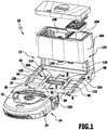
- FIG. 1 shows in perspective an occupied by the reference numeral 10 advantageous embodiment of a cleaning system according to the invention.
- the cleaning system 10 comprises a suction station 12 and an advantageous embodiment of a floor cleaning appliance 14 according to the invention.
- the floor cleaning device 14 is self-propelled and self-steering and can be moved autonomously on a floor surface to be cleaned.
- the floor cleaning device 14 includes a chassis 16.
- the chassis 16 includes two driven drive wheels 18, 19 and two castors 20, 21st
- the chassis 16 is held on the underside 22 of a housing 24 of the floor cleaning device 14.
- the drive wheels 18, 19 are arranged in the longitudinal direction 26 of the floor cleaning device 14 approximately in the center.
- the longitudinal direction 26 corresponds to a main movement direction of the floor cleaning device 14 when it is moved on the floor surface.
- the castors 20, 21 are disposed near a front side 28 of the floor cleaning device 14.
- the drive wheels 18, 19 are driven by drive motors, not shown in the drawing.
- the drive motors draw electrical energy from at least one rechargeable battery 30, which is arranged in a receiving space 31 near the front side 28.
- the battery 30 also supplies a drive motor for a cleaning unit 33 of the floor cleaning device 14 with energy, which drive motor is also not shown in the drawing.
- the cleaning unit 33 is arranged in a cleaning space 34 below the battery 30.
- the cleaning unit 33 is configured as a brush roller 36, with the dirt particles can be turned away with the floor surface to be cleaned.
- the brush roller 36 is rotatably drivable about an axis of rotation which extends in a transverse direction 38 of the floor cleaning device 14.
- the transverse direction 38 is in the FIGS. 5 to 7 aligned perpendicular to the drawing plane.
- a receptacle 40 is formed in the housing 24.
- the receptacle 40 is arranged in the transverse direction 38 between the drive wheels 18, 19.
- a dirt collecting container 42 is positioned in the receptacle 40. The dirt collecting 42 can be removed manually and in particular without tools from the receptacle 40 and inserted into this.
- the dirt collecting container 42 forms a container interior 44.
- a dirt entry opening 48 is formed in a wall 46 of the dirt collecting container 42 facing the cleaning chamber 34. Dirt particles can be conveyed from the brush roller 36 through the dirt inlet opening 48 into the container interior 44 and deposited therein.
- a cleaning unit 51 is added to a suction 50 of the floor cleaning device 14.
- the cleaning unit 51 is configured as a suction unit 52.
- the suction unit 52 is also taking advantage of the energy of the battery 30 operable.
- the container interior 44 can be acted upon under the action of the suction unit 52 with negative pressure. Dirt particles are thereby also transported under the action of the suction unit 52 in the container interior 44.
- the dirt collecting container 42 has on the underside 22 on a wall 54 which forms a bottom wall 56 of the dirt collecting container 42 in sections. In the bottom wall 56, a dirt discharge opening 58 is formed.
- the dirt discharge opening 58 comprises an opening of the wall 54.
- the floor cleaning device 14 comprises a valve device 60, which is part of the dirt collection container 42 and is covered by this.
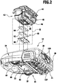
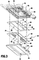
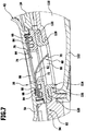
- the valve device 60 is arranged on the dirt outlet opening 58. It will be especially on the Figures 3 . 6 and 7 directed.
- the valve device 60 is air pressure actuated and is used for selectively closing or releasing the dirt outlet opening 58 so that dirt particles collected in the container interior 44 and can be removed from this in particular by suction.
- the valve device 60 comprises a first valve body 62 and a second valve body 64 and a holding part 66.
- the valve bodies 62, 64 each have a planar, strip or web-shaped configuration and are made in one piece from an elastically deformable material, for example a rubber material.
- the valve bodies 62, 64 are rectangular and have the same size.
- Each valve body 62, 64 has a holding section 68.
- the respective holding portion 68 forms a frame 69.
- the frame 69 is dimensioned so that it encloses the opening of the wall 54 and thus the dirt outlet opening 58.
- the frame 69 of the valve body 62 includes a valve portion 70 thereof, which extends in the region of the frame 69 enclosed by the opening.
- the valve portion 70 is connected only along a common edge 72 to the frame 69.
- the valve portion 70 along three other edges of the frame 69, which are the valve portion 70 facing, not connected. This allows the valve portion 70 to be deformed upon pressurization so as to move away from the frame 69, except for the connection via the common edge 72.
- the framed by the frame 69 opening is thereby partially released.
- the frame 69 of the valve body 64 includes an opening.
- the valve body 64 has a valve portion 74, which is arranged in the opening 69 enclosed by the frame this partially occlusive.
- the valve portion 74 is dimensioned so that it covers the bordered by the frame 69 opening only about one-fifth. The rest of the bordered by the frame 69 opening is free.
- the valve portion 74 is connected to the frame 69 along only one edge 76.
- the edge 76 is disposed opposite the edge 72 of the valve body 62.
- the valve portion 74 is not connected to the other, the valve portion 74 facing sides of the frame 69.
- valve portion 74 If the valve portion 74 is pressurized, it may deform so that the framed by the frame 69 opening can be released to a greater extent.
- the holding part 66 forms a frame 78 and holds a passage opening 79 a.
- the frame 78 is dimensioned such that the passage opening 79 is aligned with the openings bordered by the frames 69 of the valve bodies 62, 64 and, moreover, with the opening in the wall 54. Accordingly, the passage opening 79 is the same as the openings in the frame 69 the dirt outlet opening 58 or a part thereof.
- the valve body 62, 64 are fixed to the holding part 66 on the wall 54.
- the holding part 66 can be fixed at the edge 80 of the dirt outlet opening 58.
- the determination is made here via latching, can engage in the latching hooks 81 on the wall 54 in locking receptacles 82 on the holding part 66.
- a different type of connection for example by jamming, is possible.
- the valve body 62, 64 are arranged between the holding part 66 and the wall 54 and are fixed by the holding part 66 non-positively and positively on the wall 54.
- the valve bodies 62, 64 are clamped between the wall 54 and the holding part 66.
- projections 84 on the holding part 66 which in the present case are peg-shaped, pass through openings 85 on the frame 69 and ensure a positive fit.
- the frames 69 abut each other.
- the valve device 60 is arranged with the holding part 66 and the frame 69 of the valve body 62, 64 at the edge 80 of the dirt outlet opening 58, so that the holding part 66 as part of the edge 80 of the dirt outlet opening 58 or this can be seen forming.
- valve bodies 62, 64 are fixed to the wall 54 in such a way that they lie flat against one another when the pressure in the container interior 44 is equal to the pressure outside the container interior 44 (FIG. FIG. 6 ).
- the valve section 70 abuts flat against a strip on the valve section 74.
- Each valve body 62, 64 forms with its valve portion 70 and 74 thereby a valve seat for the respective other valve portion 74 and 70, respectively.
- the holding part 66 and the wall 54 are formed at the edge 80 so that the valve bodies 62, 64 are convexly curved in the direction of the container interior 44. Due to the elastic configuration of the valve body 62, 64 are thereby biasing the valve sections 70, 74 against each other. The valve sections 70, 74 are thereby sealingly abutting each other.
- each valve body 62, 64 assumes a closed position.
- the dirt outlet opening 58 is at least partially closed by the respective valve section 70, 74.
- the valve section 70 is dimensioned so that it closes the dirt outlet opening 58 substantially completely.
- the valve portion 70 accordingly forms a bottom wall portion 86 of the bottom wall 56.
- valve portion 74 forms a bottom wall portion 88 of the bottom wall 56.
- the bottom wall 56 is configured accordingly double-walled.
- the valve portion 74 closes the dirt discharge opening 58 only partially and to the extent that it is able to close the opening framed by the frame 69 of the valve body 64.
- an opening 90 in the housing 24 is present on the underside 22.
- the valve device 60 is disposed in the aperture 90 when the dirt collector 42 is positioned in the receptacle 40.
- the holding part 66 is closer to the bottom surface than the valve bodies 62, 64. The risk of exposure to the bottom surface arranged objects, possibly damaging the valve portions 70, 74, is thereby reduced.
- the suction station 12 is provided. With the suction station 12, dirt can be sucked out of the container interior 44 as explained below.
- the suction station 12 has a ramp-up area 92, which can be traveled by the floor cleaning device 14 and over which the suction station 12 rests on the floor surface.
- the ramp area 92 includes a ramp 94.
- the ramp 94 has an inclination relative to the horizontal, which in the present case is approximately 5 ° to approximately 10 °.
- the floor cleaner 14 may travel the ramp 94 along the main direction of travel 26 so that references to the longitudinal direction 26 and transverse direction 38 of the floor cleaner 14 may also be used for references to the suction station 12.
- the ramp 94 comprises two spaced apart in the transverse direction 38 wheel wells 96, 97, in which the drive wheels 18, 19 of the floor cleaning device 14 can be accommodated.
- the wheel wells 96, 97 are channel-shaped and have a longitudinal extent extending in the transverse direction 38.
- a suction opening 98 is formed on the ramp 94.
- the suction opening 98 comprises an opening of the ramp 94.
- a Auffahrabêt 99, 100 positioned on the ramp 94.
- the castors 20, 21 are moved when driving on the ramp 92.
- a functional region 102 of the suction station 12 adjoins the drive-on region 92.
- the functional area 102 comprises a housing 104.
- a suction unit 106 is accommodated in the housing 104 and a dirt collecting container 108 is formed.
- the dirt collector 108 can be subjected to negative pressure.
- the suction station 12 comprises a suction channel 110, which opens into the dirt collecting container 108.
- the suction channel 110 extends in sections at a rear side of the housing 104 in the direction of the bottom surface. Next, the suction passage 110 extends with an adjoining portion below the Auffahr Kunststoffes 92. At the dirt collecting container 108 remote from the end of the suction channel 110, the suction opening 98 is arranged.
- the suction station 12 has a suction channel cover 112 on the bottom side.
- the Saugkanalabdeckung 112 forms a section of a wall of the suction channel 110 and is detachably connected to the Auffahr Bachelor 92, for example by latching. This allows a user, by removing the Saugkanalabdeckung 112, the suction channel 110, if necessary, sections to open and clean.
- a vacuum can be provided by the suction unit 106, through the dirt collecting container 108 and the suction channel 110 therethrough.
- the suction station 12 comprises a sealing element 114.
- the sealing element is arranged on an edge 116 of the suction opening 98.
- the sealing element 114 is held by force and form fit on the ramp 94.
- An enclosure of the suction opening 98 engages positively and clamped in a groove 118 of the sealing element 114 a.
- the sealing element 114 may be considered as part of the edge 116 of the suction port 98 or forming this.
- the sealing element 114 is self-contained and extends along the entire edge 116.
- the sealing element 114 comprises a circumferential sealing lip 120.
- the sealing lip 120 projects upwards from the ramp 94 when it is not subjected to a force directed towards the ramp 94. This is not shown in the drawing.
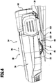
- the floor cleaning device 14 can drive onto the approach area 92 into a suction position. This is in FIG. 4 shown, in which the floor cleaning device 14 is moved in the longitudinal direction 26, wherein the drive wheels 18, 19 are not yet arranged in the wheel wells 96, 97.
- the position of the sealing element 114 is in FIG. 4 schematically represented by dashed contours 122. Between the contours 122, the suction opening 98 is arranged.
- the floor cleaning device 14 is moved so far until the drive wheels 18, 19 dip into the wheel wells 96, 97. Due to the concave configuration of the wheel wells 96, 97, this causes the floor cleaning device 14 to lower and move in the direction of the ramp 94. This has the consequence that the dirt collecting container 42 is lowered and thus the valve means 60 with the holding part 66th
- the floor cleaning device 14 assumes a suction position at the suction station 12 when the drive wheels 18, 19 are arranged in the wheel wells 96, 97.
- the edges 80 of the dirt outlet opening 58 and 116 of the suction opening 98 abut each other.
- the holding part 66 contacts the sealing element 114 in a planar manner and rests on it.
- the sealing lip 120 is curved under deformation in the direction of the ramp 94 ( FIGS. 6 and 7 ). In this way, a tight connection between the floor cleaning device 14 and the suction station 12 is provided.
- the dirt outlet opening 58 is aligned with the suction opening 98th
- the suction station 12 comprises at least one actuating element which is actuated by the floor cleaning device 14 in its suction position and by the actuation of the suction unit 106 is activated.
- two contact elements 124 are arranged on a front wall 126 of the housing 104 as actuating elements.
- the contact elements 124 are connected to a not shown control unit of the suction 12 in electrical connection, which is coupled to the suction unit 106.
- the contact elements 124 are connected to a charging unit, not shown, and can be acted upon by this with electrical energy.
- the floor cleaning device 14 comprises on the front side 28 contact elements 128, which are electrically connected to the battery 30. If the floor cleaning device 14 assumes the suction position, a respective contact element 124 contacts a contact element 128. As a result, the battery 30 can be charged.
- the current flow at the contact elements 124 is detected and a signal for activating the suction unit 106 is provided.
- the suction unit 106 is activated in the present case for a predefinable period of time, for example about 30 seconds.
- valve device 60 and in particular its valve body 62, 64 can be actuated by air pressure.
- the valve device 60 In the presence of a certain differential pressure between the air pressure in the container interior 44 and the pressure on the side facing away from the container interior 44 of the valve body 62, 64, the valve device 60 is actuated.
- valve section 70 If the suction unit 106 is activated, negative pressure is applied to the valve section 70 and the valve section 74 by the negative pressure occurring at the suction opening 98. There is a pressure difference. This has the consequence that the valve bodies 62, 64 are transferred from the closed position into an open position with deformation of the valve sections 70, 74 ( FIG. 7 ). there The valve portion 70 curves in the direction of the suction opening 98, wherein it can engage in this and also into the suction channel 110. The dirt outlet opening 58 is partially released by the valve portion 70 in its open position.
- valve section 74 which no longer bears against the valve section 70, can be deformed under the effect of the negative pressure and transferred into an open position. Also, the valve portion 74 releases the dirt outlet opening 58 in the open position partially. Between the valve sections 70, 74 thereby a passage 130 is formed.
- a suction flow can form.
- the suction flow passes through the cleaning room 34 communicating with the atmosphere and the dirt inlet opening 48 into the container interior 44, through the dirt outlet opening 58, the passage 130, the suction opening 98 and the suction channel 110 into the dirt collecting container 108. Dirt particles thereby escape from the container interior 44 sucked off and deposited in the dirt collector 108. As a result of the suction flow adhering to the brush roller 36 dirt particles are detected and sucked.
- the dirt collector 42 can be emptied particularly effective.
- valve portions 70, 74 are elastically deformable, they automatically return from the open position to the closed position, in which they again for sealing the dirt outlet opening 58 abut each other.
- valve body 64 which closes the dirt outlet opening 58 only to a smaller extent is arranged with the valve section 74 on the side of the valve body 62 facing the container interior 44, which substantially completely closes the dirt outlet opening 58 with the valve section 70.
- the floor cleaning device 14 can again depart from the drive-up region 92 and continue the cleaning operation.
- the floor cleaning device 14 For entering the suction station 12, the floor cleaning device 14 has a sensor system known per se, which enables contactless orientation of the floor cleaning device 14 relative to the suction station 12. This allows the floor cleaning device 14 to position itself on the suction station 12 in such a way that it can drive into the ramp-up area 92 when driving straight ahead.
- the suction station 12 has supportive guide elements 132, 133, which allow contact-based guidance of the floor cleaning device 14 in the suction position.
- the guide elements 132, 133 are configured as rib-shaped guide projections 134, 135 adjacent to both sides of the ramp-up area 92 and the wheel wells 96, 97.
- the floor cleaning device 14 can contact the guide projections 134, 135 with contact sensors and thereby be guided by contact.
- a contact sensor serve lateral brush covers 136, 137 of the housing 24.
- the brush covers 136, 137 are displaceable in the transverse direction 38, like this in the DE 10 2012 104 326 A1 is described.
- the floor cleaning device 14 it is possible for the floor cleaning device 14 to change the direction of travel in such a way that it can drive in as straight as possible onto the ramp-up area 92 and into the suction position.
Landscapes
- Engineering & Computer Science (AREA)
- Mechanical Engineering (AREA)
- Cleaning In General (AREA)
- Electric Vacuum Cleaner (AREA)
- Electric Suction Cleaners (AREA)
Claims (21)
- Appareil de nettoyage du sol autotracté et autodirigé comprenant au moins un agrégat de nettoyage (33, 51) et un collecteur de saletés (42) présentant un espace intérieur de réservoir (44), une paroi de sol (56), une ouverture d'entrée de saletés (48) et une ouverture de sortie de saletés (58), des particules de saletés pouvant être transférées dans l'espace intérieur de réservoir (44) au moyen du au moins un agrégat de nettoyage (33, 51) et l'ouverture de sortie de saletés (58) se formant sur la paroi de sol (56), l'appareil de nettoyage du sol (14) présentant un dispositif de soupape (60), placé sur l'ouverture de sortie de saletés (58) avec au moins un corps de soupape (62, 64) formant, au moins par tronçon, dans une position de fermeture, la paroi de sol (56) et fermant l'ouverture de sortie de saletés (58) et qui peut être transféré dans une position d'ouverture dans laquelle l'ouverture de sortie de saletés (58) est au moins partiellement dégagée, et le dispositif de soupape (60) pouvant être actionné sous l'effet de la pression de l'air pour faire passer le au moins un corps de soupape (62, 64) de la position de fermeture à la position d'ouverture.
- Appareil de nettoyage du sol selon la revendication 1, caractérisé en ce que le au moins un corps de soupape (62, 64) peut passer de la position de fermeture à la position d'ouverture dans une direction dirigeant loin de l'espace intérieur de réservoir (44).
- Appareil de nettoyage du sol selon la revendication 1 ou 2, caractérisé en ce que le dispositif de soupape (60) présente un corps de soupape (62) fermant, dans la position de fermeture, l'ouverture de sortie de saletés (58) entièrement ou essentiellement entièrement.
- Appareil de nettoyage du sol selon l'une quelconque des revendications précédentes, caractérisé en ce que le dispositif de soupape (60) présente un corps de soupape (64) fermant partiellement, dans la position de fermeture, l'ouverture de sortie de saletés (58), en particulier en ce que le dispositif de soupape (60) présente deux corps de soupape (62, 64) ou plus fermant, dans la position de fermeture, l'ouverture de sortie de saletés (58) respectivement de leur côté partiellement et, en commun entièrement ou essentiellement entièrement.
- Appareil de nettoyage du sol selon l'une quelconque des revendications précédentes, caractérisé en ce que le dispositif de soupape (60) présente deux corps de soupape (62, 64) s'appliquant à plat l'un sur l'autre dans la position de fermeture pour fermer l'ouverture de sortie de saletés (58), en particulier en ce que les corps de soupape (62, 64) sont placés de manière superposée sur l'ouverture de sortie de saletés (58).
- Appareil de nettoyage du sol selon l'une quelconque des revendications précédentes, caractérisé en ce que le au moins un corps de soupape (62, 64) présente une grande étendue, du moins sur un segment de soupape (70, 74) formant au moins par tronçon la paroi de sol (56).
- Appareil de nettoyage du sol selon l'une quelconque des revendications précédentes, caractérisé en ce que le au moins un corps de soupape (62, 64) est composé d'un matériau déformable de manière élastique et pouvant être déformé pour passer de la position de fermeture à la position d'ouverture.
- Appareil de nettoyage du sol selon l'une quelconque des revendications précédentes, caractérisé en ce que le au moins un corps de soupape (62, 64) peut passer automatiquement de la position d'ouverture à la position de fermeture.
- Appareil de nettoyage du sol selon l'une quelconque des revendications précédentes, caractérisé en ce que le au moins un corps de soupape (62, 64) présente un segment de soupape (70, 74) formant au moins par tronçon la paroi de sol (56) et un segment de retenue (68) grâce auquel le au moins un corps de soupape (62, 64) est maintenu sur le collecteur de saletés (42), en particulier en ce que le segment de retenue (68) forme un cadre (69) entourant le segment de soupape (70, 74).
- Appareil de nettoyage du sol selon l'une quelconque des revendications précédentes, caractérisé en ce que le dispositif de soupape (60) présente une pièce de retenue (66) grâce à laquelle le au moins un corps de soupape (62, 64) est fixé sur un bord (80) de l'ouverture de sortie de saletés (58) sur le collecteur de saletés (42), en particulier en ce que la pièce de retenue (66) forme un cadre (78) entourant l'ouverture de sortie de saletés (58).
- Appareil de nettoyage du sol selon l'une quelconque des revendications précédentes, caractérisé en ce que le au moins un corps de soupape (62, 64) est, par rapport à un côté de l'appareil de nettoyage du sol (14) faisant face à une surface d'exposition de l'appareil de nettoyage du sol (14), déplacé sur le collecteur de saletés (42) dans la direction de l'espace intérieur de réservoir (44).
- Appareil de nettoyage du sol selon l'une quelconque des revendications précédentes, caractérisé en ce que l'appareil de nettoyage du sol (14) présente un logement (40) pour le collecteur de saletés (42) et en ce que le collecteur de saletés (42) est positionné de manière amovible dans le logement (40).
- Appareil de nettoyage du sol selon l'une quelconque des revendications précédentes, caractérisé en ce que l'appareil de nettoyage du sol (14) présente un châssis (16) avec deux roues d'entraînement (18, 19) et en ce que le collecteur de saletés (42) est positionné sur l'appareil de nettoyage du sol (14) de telle sorte que l'ouverture de sortie de saletés (58) est placée, dans une direction transversale (38) de l'appareil de nettoyage du sol (14), entre les roues d'entraînement (18, 19) et, dans sa direction longitudinale (26), dans la hauteur ou à peu près dans la hauteur des roues d'entraînement (18, 19).
- Appareil de nettoyage du sol selon l'une quelconque des revendications précédentes, caractérisé en ce qu'on utilise comme agrégat de nettoyage (33, 51) un rouleau à brosse (36), avec lequel les particules de saletés peuvent être enlevées d'une surface au sol à nettoyer et/ou un agrégat d'aspiration (52) mettant sous dépression l'espace intérieur de réservoir (44).
- Système de nettoyage comprenant un appareil de nettoyage du sol (14) autotracté et autodirigé, selon l'une quelconque des revendications précédentes, et une station d'aspiration (12) comprenant un agrégat d'aspiration (106), un collecteur de saletés (108) mis sous dépression par ce dernier et une ouverture d'aspiration (98), placée sur le collecteur de saletés (108) ou sur un canal d'aspiration (110) relié au collecteur de saletés, dans lequel l'ouverture de sortie de saletés (58), dans une position d'aspiration de l'appareil de nettoyage du sol (14) sur la station d'aspiration (12), est alignée au moins partiellement avec l'ouverture d'aspiration (98), le au moins un corps de soupape (62, 64) pouvant être mis sous dépression en activant l'agrégat d'aspiration (106) de la station d'aspiration (12) et pouvant passer de la position de fermeture à la position d'ouverture.
- Système de nettoyage selon la revendication 15, caractérisé en ce que la station d'aspiration (12) comprend ou forme une zone d'accession (92) pour l'appareil de nettoyage du sol (14) et en ce que l'ouverture d'aspiration (98) est formée dans la zone d'accession (92).
- Système de nettoyage selon la revendication 16, caractérisé en ce que l'appareil de nettoyage du sol (14) présente un châssis (16) avec au moins une roue (18-21) et en ce que la zone d'accession (92) comprend au moins une auge de roue (96, 97) dans laquelle est placée la au moins une roue (18-21) dans la position d'aspiration de l'appareil de nettoyage du sol (14), en particulier en ce que l'appareil de nettoyage du sol (14) s'abaisse, lors de l'insertion dans l'auge de roue (96, 97), dans la direction de l'ouverture d'aspiration (98) et s'applique sur un bord (116) de l'ouverture d'aspiration (98).
- Système de nettoyage selon la revendication 15 à 17, caractérisé en ce que la station d'aspiration (12) comprend au moins un élément d'étanchéité (114), de préférence un joint (120), placé sur un bord (116) de l'ouverture d'aspiration (98) et étant en contact avec un bord (80) de l'ouverture de sortie de saletés (58) lorsque l'appareil de nettoyage du sol (14) se met en position d'aspiration, en particulier en ce que le au moins un élément d'étanchéité (114) s'étend le long du bord (116) complet de l'ouverture d'aspiration (98).
- Système de nettoyage selon la revendication 15 à 18, caractérisé en ce que l'agrégat d'aspiration (106) de la station d'aspiration (12) est activé lorsque l'appareil de nettoyage du sol (14) se met en position d'aspiration.
- Système de nettoyage selon la revendication 19, caractérisé en ce que l'agrégat d'aspiration (106) est activé pour une période pouvant être prédéfinie et/ou en ce que la station d'aspiration (12) comprend au moins un élément d'actionnement (124), actionné par l'appareil de nettoyage du sol (14) en position d'aspiration pour activer l'agrégat d'aspiration (106).
- Système de nettoyage selon l'une quelconque des revendications 15 à 20, caractérisé en ce que la station d'aspiration (12) comprend un canal d'aspiration (110) présentant l'ouverture d'aspiration (98) qui débouche dans le collecteur de saletés (106) de la station d'aspiration (12), en particulier en ce que le canal d'aspiration (110) passe au moins par tronçon sous une zone d'accession (92) de la station d'aspiration (12) pour l'appareil de nettoyage du sol (14) et comprend un cache de canal d'aspiration (112) pouvant être relié de manière amovible à la zone de départ (92).
Priority Applications (1)
| Application Number | Priority Date | Filing Date | Title |
|---|---|---|---|
| PL13799615T PL3076843T3 (pl) | 2013-12-06 | 2013-12-06 | Samojezdne i samokierujące urządzenie do czyszczenia podłoża i system czyszczący |
Applications Claiming Priority (1)
| Application Number | Priority Date | Filing Date | Title |
|---|---|---|---|
| PCT/EP2013/075829 WO2015082019A1 (fr) | 2013-12-06 | 2013-12-06 | Appareil de nettoyage des sols automoteur et autodirecteur, et système de nettoyage |
Publications (2)
| Publication Number | Publication Date |
|---|---|
| EP3076843A1 EP3076843A1 (fr) | 2016-10-12 |
| EP3076843B1 true EP3076843B1 (fr) | 2017-10-25 |
Family
ID=49713105
Family Applications (1)
| Application Number | Title | Priority Date | Filing Date |
|---|---|---|---|
| EP13799615.3A Active EP3076843B1 (fr) | 2013-12-06 | 2013-12-06 | Appareil de nettoyage du sol autotracté et autodirecteur et système de nettoyage |
Country Status (6)
| Country | Link |
|---|---|
| US (1) | US20160278596A1 (fr) |
| EP (1) | EP3076843B1 (fr) |
| KR (1) | KR20160096099A (fr) |
| CN (1) | CN105848549B (fr) |
| PL (1) | PL3076843T3 (fr) |
| WO (1) | WO2015082019A1 (fr) |
Families Citing this family (49)
| Publication number | Priority date | Publication date | Assignee | Title |
|---|---|---|---|---|
| JP6335050B2 (ja) * | 2014-07-04 | 2018-05-30 | 東芝ライフスタイル株式会社 | 電気掃除機 |
| US9462920B1 (en) | 2015-06-25 | 2016-10-11 | Irobot Corporation | Evacuation station |
| DE102016114338A1 (de) * | 2016-08-03 | 2018-02-08 | Miele & Cie. Kg | Ladevorrichtung für ein Haushaltgerät und Verfahren zum Aufladen eines Haushaltgeräts |
| US10292554B2 (en) * | 2016-10-28 | 2019-05-21 | Irobot Corporation | Mobile cleaning robot with a bin |
| CN109620064B (zh) * | 2016-12-16 | 2021-10-26 | 云鲸智能科技(东莞)有限公司 | 用于清洁机器人系统的基站 |
| JP2018196511A (ja) * | 2017-05-23 | 2018-12-13 | 東芝ライフスタイル株式会社 | 電気掃除装置 |
| DE102017208967B4 (de) | 2017-05-29 | 2024-02-22 | BSH Hausgeräte GmbH | Saugreinigungsroboter |
| DE102017208970A1 (de) | 2017-05-29 | 2018-11-29 | BSH Hausgeräte GmbH | Stützanordnung an einem Reinigungsroboter |
| JP6910864B2 (ja) * | 2017-06-22 | 2021-07-28 | 東芝ライフスタイル株式会社 | 電気掃除装置 |
| JP6933924B2 (ja) * | 2017-06-23 | 2021-09-08 | 東芝ライフスタイル株式会社 | 電気掃除装置 |
| AU2018204467A1 (en) * | 2017-06-27 | 2019-01-17 | Bissell Inc. | Supply and/or disposal system for autonomous floor cleaner |
| US10383499B2 (en) | 2017-08-31 | 2019-08-20 | Irobot Corporation | Wet robot docking station |
| CN107713920B (zh) * | 2017-09-25 | 2022-06-03 | 北京石头创新科技有限公司 | 自动清洁设备及其充电的方法 |
| CN108209747A (zh) * | 2017-12-29 | 2018-06-29 | 北京视觉世界科技有限公司 | 垃圾处理方法、装置、计算机设备和存储介质 |
| CN108609318A (zh) * | 2018-05-10 | 2018-10-02 | 深圳市宇辰智能科技有限公司 | 一种垃圾排放工作站 |
| JP6993937B2 (ja) * | 2018-06-22 | 2022-01-14 | 東芝ライフスタイル株式会社 | 電気掃除装置 |
| CN111246786B (zh) | 2018-07-20 | 2022-07-29 | 尚科宁家运营有限公司 | 机器人清洁器杂物移除对接站 |
| KR102620360B1 (ko) * | 2018-12-14 | 2024-01-04 | 삼성전자주식회사 | 로봇 청소기, 스테이션 및 청소 시스템 |
| CN109797980B (zh) * | 2019-02-01 | 2023-05-30 | 上海逍森自动化科技有限公司 | 一种高空玻璃蒸汽清洗机器人 |
| CN111743459B (zh) * | 2019-03-29 | 2024-07-16 | 北京石头世纪科技股份有限公司 | 智能清洁系统、自主机器人和基站 |
| CN109846418A (zh) * | 2019-03-30 | 2019-06-07 | 深圳市银星智能科技股份有限公司 | 清洁系统 |
| DE102019109634A1 (de) * | 2019-04-11 | 2020-10-15 | Vorwerk & Co. Interholding Gmbh | Sich selbsttätig fortbewegender Saugroboter sowie System aus einem sich selbsttätig fortbewegenden Saugroboter und einem externen Saugreinigungsgerät |
| DE102019112779B3 (de) * | 2019-05-15 | 2020-10-15 | Carl Freudenberg Kg | Reinigungsvorrichtung für die Reinigung einer rotierbaren Bürstenwalze eines Reinigungsgerätes und Reinigungssystem |
| KR102730954B1 (ko) * | 2019-06-25 | 2024-11-18 | 삼성전자주식회사 | 로봇 청소기, 스테이션 및 청소 시스템 |
| US11730329B2 (en) * | 2019-12-06 | 2023-08-22 | Bissell Inc. | Autonomous floor cleaner and docking station |
| CN111110123A (zh) * | 2019-12-28 | 2020-05-08 | 尚科宁家(中国)科技有限公司 | 用于扫地机器人的排空站 |
| CN113303734A (zh) * | 2020-02-27 | 2021-08-27 | 佛山市云米电器科技有限公司 | 清洁机器人的控制方法及清洁系统 |
| CN212465864U (zh) * | 2020-04-30 | 2021-02-05 | 追创科技(苏州)有限公司 | 自移动清洁设备及清洁系统 |
| JP2021194152A (ja) * | 2020-06-11 | 2021-12-27 | パナソニックIpマネジメント株式会社 | 掃除機システム、自律走行型掃除機、保持装置、及び制御装置 |
| KR20220006850A (ko) | 2020-07-09 | 2022-01-18 | 엘지전자 주식회사 | 청소기 스테이션 |
| WO2022032640A1 (fr) * | 2020-08-14 | 2022-02-17 | Irobot Corporation | Socle d'accueil d'évacuation avec une gestion de fluide |
| CN216569815U (zh) * | 2020-09-02 | 2022-05-24 | 尚科宁家运营有限公司 | 用于机器人清洁器的对接站、机器人清洁器以及系统 |
| US11910974B2 (en) * | 2020-10-03 | 2024-02-27 | Viabot Inc. | Conveyor stations for emptying debris collecting robots |
| KR102466280B1 (ko) * | 2020-12-02 | 2022-11-14 | 삼성전자주식회사 | 로봇청소기 스테이션 |
| CN113143123A (zh) * | 2021-02-03 | 2021-07-23 | 深圳乐动机器人有限公司 | 一种清洁机器人系统及清洁控制方法 |
| CN112793963A (zh) * | 2021-03-09 | 2021-05-14 | 广州科语机器人有限公司 | 一种垃圾回收站 |
| US20220287527A1 (en) * | 2021-03-15 | 2022-09-15 | Irobot Corporation | Evacuation Station |
| CN113171027A (zh) * | 2021-04-02 | 2021-07-27 | 美智纵横科技有限责任公司 | 清洁装置、尘盒组件、控制方法及控制系统 |
| USD981061S1 (en) * | 2021-04-12 | 2023-03-14 | Zhichang Technology (Suzhou) Co., Ltd. | Cleaning robot workstation |
| CN113261891B (zh) * | 2021-06-08 | 2025-09-05 | 尚科宁家(中国)科技有限公司 | 一种用于清洁机器人的基站 |
| CN114587186A (zh) * | 2021-06-28 | 2022-06-07 | 北京石头世纪科技股份有限公司 | 尘盒、自动清洁设备以及集尘桩 |
| US20240389808A1 (en) * | 2021-09-14 | 2024-11-28 | Lg Electronics Inc. | Cleaner station |
| CN115886642A (zh) * | 2021-09-30 | 2023-04-04 | 深圳银星智能集团股份有限公司 | 尘盒组件、清洁机器人及其系统 |
| CN114027747B (zh) * | 2021-10-29 | 2022-11-22 | 深圳乐动机器人有限公司 | 清洗装置 |
| CA212097S (en) * | 2022-01-01 | 2023-02-07 | Beijing Roborock Technology Co Ltd | Docking station for cleaning robot |
| KR102804706B1 (ko) * | 2022-10-04 | 2025-05-12 | 엘지전자 주식회사 | 로봇 청소기 및 청소기 시스템 |
| KR20250166243A (ko) * | 2023-04-20 | 2025-11-27 | 샤크닌자 오퍼레이팅 엘엘씨 | 진공 청소기 |
| CA232298S (en) * | 2024-01-05 | 2025-05-12 | Beijing Roborock Technology Co Ltd | Multifunctional docking station for cleaning robot |
| WO2025198144A1 (fr) * | 2024-03-20 | 2025-09-25 | 삼성전자주식회사 | Robot de nettoyage, station et dispositif de nettoyage |
Family Cites Families (10)
| Publication number | Priority date | Publication date | Assignee | Title |
|---|---|---|---|---|
| BE1008470A3 (fr) | 1994-07-04 | 1996-05-07 | Colens Andre | Dispositif et systeme automatique de depoussierage de sol et engin y adapte. |
| DE10110907A1 (de) * | 2001-03-07 | 2002-09-19 | Kaercher Gmbh & Co Alfred | Bodenreinigungsgerät |
| JP3528807B2 (ja) * | 2001-03-29 | 2004-05-24 | 松下電器産業株式会社 | 電気掃除機 |
| JP4567621B2 (ja) * | 2006-03-14 | 2010-10-20 | 日立アプライアンス株式会社 | 電気掃除機 |
| CN101352326A (zh) * | 2007-07-23 | 2009-01-28 | 泰怡凯电器(苏州)有限公司 | 一种自动清洁器用的垃圾收集装置 |
| DE102010017213A1 (de) * | 2010-06-02 | 2011-12-08 | Vorwerk & Co. Interholding Gmbh | Entleerungsstation für einen Schmutzsammelbehälter eines Reinigungsgerätes sowie Verfahren hierzu |
| KR101483541B1 (ko) | 2010-07-15 | 2015-01-19 | 삼성전자주식회사 | 로봇청소기, 메인터넌스 스테이션 그리고 이들을 가지는 청소시스템 |
| KR101496913B1 (ko) * | 2010-11-03 | 2015-03-02 | 삼성전자 주식회사 | 로봇청소기와 자동배출 스테이션 및 이를 가지는 로봇청소기 시스템 |
| DK2640247T3 (da) * | 2010-11-16 | 2019-07-08 | Kaercher Alfred Se & Co Kg | Støvsuger med mindst et sugeaggregat |
| DE102012104326A1 (de) | 2012-05-18 | 2013-11-21 | Alfred Kärcher Gmbh & Co. Kg | Selbstfahrendes und selbstlenkendes Bodenreinigungsgerät sowie Verfahren zur Steuerung von dessen Bewegung |
-
2013
- 2013-12-06 CN CN201380081440.8A patent/CN105848549B/zh active Active
- 2013-12-06 KR KR1020167015987A patent/KR20160096099A/ko not_active Withdrawn
- 2013-12-06 PL PL13799615T patent/PL3076843T3/pl unknown
- 2013-12-06 WO PCT/EP2013/075829 patent/WO2015082019A1/fr not_active Ceased
- 2013-12-06 EP EP13799615.3A patent/EP3076843B1/fr active Active
-
2016
- 2016-06-03 US US15/172,672 patent/US20160278596A1/en not_active Abandoned
Non-Patent Citations (1)
| Title |
|---|
| None * |
Also Published As
| Publication number | Publication date |
|---|---|
| CN105848549B (zh) | 2018-03-06 |
| US20160278596A1 (en) | 2016-09-29 |
| WO2015082019A9 (fr) | 2015-07-30 |
| PL3076843T3 (pl) | 2018-03-30 |
| KR20160096099A (ko) | 2016-08-12 |
| WO2015082019A1 (fr) | 2015-06-11 |
| CN105848549A (zh) | 2016-08-10 |
| EP3076843A1 (fr) | 2016-10-12 |
Similar Documents
| Publication | Publication Date | Title |
|---|---|---|
| EP3076843A1 (fr) | Appareil de nettoyage des sols automoteur et autodirecteur, et système de nettoyage | |
| EP3705012B1 (fr) | Station de collecte de produit aspiré, appareil de nettoyage par aspiration ainsi que système d'une station de collecte de produit aspiré et d'un appareil de nettoyage par aspiration | |
| EP2974640B1 (fr) | Robot aspirateur dote d'un rouleau de soie et procede de nettoyage pour un rouleau de soie d'un robot aspirateur | |
| EP3451886B1 (fr) | Système de traitement des sols | |
| DE102010017213A1 (de) | Entleerungsstation für einen Schmutzsammelbehälter eines Reinigungsgerätes sowie Verfahren hierzu | |
| EP3409165B1 (fr) | Dispositif de support sur un robot de nettoyage | |
| EP0989255A1 (fr) | Appareil de nettoyage pour piscine | |
| EP2514533B1 (fr) | Appareil de nettoyage autotracté destiné au nettoyage de modules solaires | |
| DE102013103086B4 (de) | Absaugstation für ein selbsttätig verfahrbares Bodenreinigungsgerät sowie Kombination einer Absaugstation mit einem solchen Gerät | |
| DE202017001077U1 (de) | Staubsauger | |
| DE1928713A1 (de) | Fussbodenreinigungsgeraet | |
| DE102018116225A1 (de) | Reinigungsgerät | |
| DE102009034955B4 (de) | Selbsttätig verfahrbares Bodenstaub-Aufsammelgerät | |
| DE102014100358B4 (de) | Selbstfahrendes Reinigungsgerät | |
| DE102014108217A1 (de) | Reinigungssystem | |
| DE102019101116A1 (de) | Stationierungseinrichtung für ein Reinigungsgerät und Verfahren zum Stationieren des Reinigungsgeräts | |
| DE102017001985A1 (de) | Außenreinigungsvorrichtung für ein Kraftfahrzeug und Kraftfahrzeug mit einer solchen Außenreinigungsvorrichtung | |
| DE102013103734A1 (de) | Fasspumpe | |
| DE2150496A1 (de) | Fahrbare reinigungsmaschine | |
| EP3451887B1 (fr) | Système de traîtement des sols | |
| DE102015101647B4 (de) | Saugdüse | |
| EP4429532B1 (fr) | Aspirateur de sol automatique | |
| DE102013007408A1 (de) | Entleer- und Reinigungsstation mit Aufnahmekassette | |
| DE29923351U1 (de) | Waschfahrzeug für Abfallsammelbehälter | |
| WO2020147970A1 (fr) | Dispositif de nettoyage des sols |
Legal Events
| Date | Code | Title | Description |
|---|---|---|---|
| PUAI | Public reference made under article 153(3) epc to a published international application that has entered the european phase |
Free format text: ORIGINAL CODE: 0009012 |
|
| 17P | Request for examination filed |
Effective date: 20160421 |
|
| AK | Designated contracting states |
Kind code of ref document: A1 Designated state(s): AL AT BE BG CH CY CZ DE DK EE ES FI FR GB GR HR HU IE IS IT LI LT LU LV MC MK MT NL NO PL PT RO RS SE SI SK SM TR |
|
| AX | Request for extension of the european patent |
Extension state: BA ME |
|
| RIN1 | Information on inventor provided before grant (corrected) |
Inventor name: KURMANN, RAINER Inventor name: HOLZER, ANNETTE Inventor name: JANZEN, JACOB |
|
| DAX | Request for extension of the european patent (deleted) | ||
| GRAP | Despatch of communication of intention to grant a patent |
Free format text: ORIGINAL CODE: EPIDOSNIGR1 |
|
| INTG | Intention to grant announced |
Effective date: 20170516 |
|
| GRAS | Grant fee paid |
Free format text: ORIGINAL CODE: EPIDOSNIGR3 |
|
| GRAA | (expected) grant |
Free format text: ORIGINAL CODE: 0009210 |
|
| AK | Designated contracting states |
Kind code of ref document: B1 Designated state(s): AL AT BE BG CH CY CZ DE DK EE ES FI FR GB GR HR HU IE IS IT LI LT LU LV MC MK MT NL NO PL PT RO RS SE SI SK SM TR |
|
| REG | Reference to a national code |
Ref country code: GB Ref legal event code: FG4D Free format text: NOT ENGLISH |
|
| REG | Reference to a national code |
Ref country code: CH Ref legal event code: EP Ref country code: CH Ref legal event code: NV Representative=s name: ISLER AND PEDRAZZINI AG, CH |
|
| REG | Reference to a national code |
Ref country code: FR Ref legal event code: PLFP Year of fee payment: 5 |
|
| REG | Reference to a national code |
Ref country code: AT Ref legal event code: REF Ref document number: 939082 Country of ref document: AT Kind code of ref document: T Effective date: 20171115 |
|
| REG | Reference to a national code |
Ref country code: IE Ref legal event code: FG4D Free format text: LANGUAGE OF EP DOCUMENT: GERMAN |
|
| REG | Reference to a national code |
Ref country code: DE Ref legal event code: R096 Ref document number: 502013008673 Country of ref document: DE |
|
| REG | Reference to a national code |
Ref country code: NL Ref legal event code: MP Effective date: 20171025 |
|
| REG | Reference to a national code |
Ref country code: LT Ref legal event code: MG4D |
|
| PG25 | Lapsed in a contracting state [announced via postgrant information from national office to epo] |
Ref country code: NL Free format text: LAPSE BECAUSE OF FAILURE TO SUBMIT A TRANSLATION OF THE DESCRIPTION OR TO PAY THE FEE WITHIN THE PRESCRIBED TIME-LIMIT Effective date: 20171025 |
|
| PG25 | Lapsed in a contracting state [announced via postgrant information from national office to epo] |
Ref country code: FI Free format text: LAPSE BECAUSE OF FAILURE TO SUBMIT A TRANSLATION OF THE DESCRIPTION OR TO PAY THE FEE WITHIN THE PRESCRIBED TIME-LIMIT Effective date: 20171025 Ref country code: NO Free format text: LAPSE BECAUSE OF FAILURE TO SUBMIT A TRANSLATION OF THE DESCRIPTION OR TO PAY THE FEE WITHIN THE PRESCRIBED TIME-LIMIT Effective date: 20180125 Ref country code: LT Free format text: LAPSE BECAUSE OF FAILURE TO SUBMIT A TRANSLATION OF THE DESCRIPTION OR TO PAY THE FEE WITHIN THE PRESCRIBED TIME-LIMIT Effective date: 20171025 Ref country code: SE Free format text: LAPSE BECAUSE OF FAILURE TO SUBMIT A TRANSLATION OF THE DESCRIPTION OR TO PAY THE FEE WITHIN THE PRESCRIBED TIME-LIMIT Effective date: 20171025 Ref country code: ES Free format text: LAPSE BECAUSE OF FAILURE TO SUBMIT A TRANSLATION OF THE DESCRIPTION OR TO PAY THE FEE WITHIN THE PRESCRIBED TIME-LIMIT Effective date: 20171025 |
|
| PG25 | Lapsed in a contracting state [announced via postgrant information from national office to epo] |
Ref country code: HR Free format text: LAPSE BECAUSE OF FAILURE TO SUBMIT A TRANSLATION OF THE DESCRIPTION OR TO PAY THE FEE WITHIN THE PRESCRIBED TIME-LIMIT Effective date: 20171025 Ref country code: BG Free format text: LAPSE BECAUSE OF FAILURE TO SUBMIT A TRANSLATION OF THE DESCRIPTION OR TO PAY THE FEE WITHIN THE PRESCRIBED TIME-LIMIT Effective date: 20180125 Ref country code: IS Free format text: LAPSE BECAUSE OF FAILURE TO SUBMIT A TRANSLATION OF THE DESCRIPTION OR TO PAY THE FEE WITHIN THE PRESCRIBED TIME-LIMIT Effective date: 20180225 Ref country code: LV Free format text: LAPSE BECAUSE OF FAILURE TO SUBMIT A TRANSLATION OF THE DESCRIPTION OR TO PAY THE FEE WITHIN THE PRESCRIBED TIME-LIMIT Effective date: 20171025 Ref country code: GR Free format text: LAPSE BECAUSE OF FAILURE TO SUBMIT A TRANSLATION OF THE DESCRIPTION OR TO PAY THE FEE WITHIN THE PRESCRIBED TIME-LIMIT Effective date: 20180126 Ref country code: RS Free format text: LAPSE BECAUSE OF FAILURE TO SUBMIT A TRANSLATION OF THE DESCRIPTION OR TO PAY THE FEE WITHIN THE PRESCRIBED TIME-LIMIT Effective date: 20171025 |
|
| REG | Reference to a national code |
Ref country code: DE Ref legal event code: R082 Ref document number: 502013008673 Country of ref document: DE Representative=s name: HOEGER, STELLRECHT & PARTNER PATENTANWAELTE MB, DE Ref country code: DE Ref legal event code: R081 Ref document number: 502013008673 Country of ref document: DE Owner name: ALFRED KAERCHER SE & CO. KG, DE Free format text: FORMER OWNER: ALFRED KAERCHER GMBH & CO. KG, 71364 WINNENDEN, DE |
|
| REG | Reference to a national code |
Ref country code: DE Ref legal event code: R097 Ref document number: 502013008673 Country of ref document: DE |
|
| PG25 | Lapsed in a contracting state [announced via postgrant information from national office to epo] |
Ref country code: SK Free format text: LAPSE BECAUSE OF FAILURE TO SUBMIT A TRANSLATION OF THE DESCRIPTION OR TO PAY THE FEE WITHIN THE PRESCRIBED TIME-LIMIT Effective date: 20171025 Ref country code: CZ Free format text: LAPSE BECAUSE OF FAILURE TO SUBMIT A TRANSLATION OF THE DESCRIPTION OR TO PAY THE FEE WITHIN THE PRESCRIBED TIME-LIMIT Effective date: 20171025 Ref country code: DK Free format text: LAPSE BECAUSE OF FAILURE TO SUBMIT A TRANSLATION OF THE DESCRIPTION OR TO PAY THE FEE WITHIN THE PRESCRIBED TIME-LIMIT Effective date: 20171025 Ref country code: EE Free format text: LAPSE BECAUSE OF FAILURE TO SUBMIT A TRANSLATION OF THE DESCRIPTION OR TO PAY THE FEE WITHIN THE PRESCRIBED TIME-LIMIT Effective date: 20171025 Ref country code: CY Free format text: LAPSE BECAUSE OF FAILURE TO SUBMIT A TRANSLATION OF THE DESCRIPTION OR TO PAY THE FEE WITHIN THE PRESCRIBED TIME-LIMIT Effective date: 20171025 |
|
| RAP2 | Party data changed (patent owner data changed or rights of a patent transferred) |
Owner name: ALFRED KAERCHER SE & CO. KG |
|
| PG25 | Lapsed in a contracting state [announced via postgrant information from national office to epo] |
Ref country code: SM Free format text: LAPSE BECAUSE OF FAILURE TO SUBMIT A TRANSLATION OF THE DESCRIPTION OR TO PAY THE FEE WITHIN THE PRESCRIBED TIME-LIMIT Effective date: 20171025 |
|
| PLBE | No opposition filed within time limit |
Free format text: ORIGINAL CODE: 0009261 |
|
| STAA | Information on the status of an ep patent application or granted ep patent |
Free format text: STATUS: NO OPPOSITION FILED WITHIN TIME LIMIT |
|
| REG | Reference to a national code |
Ref country code: IE Ref legal event code: MM4A |
|
| GBPC | Gb: european patent ceased through non-payment of renewal fee |
Effective date: 20180125 |
|
| PG25 | Lapsed in a contracting state [announced via postgrant information from national office to epo] |
Ref country code: MT Free format text: LAPSE BECAUSE OF FAILURE TO SUBMIT A TRANSLATION OF THE DESCRIPTION OR TO PAY THE FEE WITHIN THE PRESCRIBED TIME-LIMIT Effective date: 20171025 Ref country code: LU Free format text: LAPSE BECAUSE OF NON-PAYMENT OF DUE FEES Effective date: 20171206 |
|
| 26N | No opposition filed |
Effective date: 20180726 |
|
| REG | Reference to a national code |
Ref country code: BE Ref legal event code: MM Effective date: 20171231 |
|
| PG25 | Lapsed in a contracting state [announced via postgrant information from national office to epo] |
Ref country code: IE Free format text: LAPSE BECAUSE OF NON-PAYMENT OF DUE FEES Effective date: 20171206 |
|
| PG25 | Lapsed in a contracting state [announced via postgrant information from national office to epo] |
Ref country code: SI Free format text: LAPSE BECAUSE OF FAILURE TO SUBMIT A TRANSLATION OF THE DESCRIPTION OR TO PAY THE FEE WITHIN THE PRESCRIBED TIME-LIMIT Effective date: 20171025 Ref country code: GB Free format text: LAPSE BECAUSE OF NON-PAYMENT OF DUE FEES Effective date: 20180125 Ref country code: BE Free format text: LAPSE BECAUSE OF NON-PAYMENT OF DUE FEES Effective date: 20171231 |
|
| PG25 | Lapsed in a contracting state [announced via postgrant information from national office to epo] |
Ref country code: MC Free format text: LAPSE BECAUSE OF FAILURE TO SUBMIT A TRANSLATION OF THE DESCRIPTION OR TO PAY THE FEE WITHIN THE PRESCRIBED TIME-LIMIT Effective date: 20171025 Ref country code: HU Free format text: LAPSE BECAUSE OF FAILURE TO SUBMIT A TRANSLATION OF THE DESCRIPTION OR TO PAY THE FEE WITHIN THE PRESCRIBED TIME-LIMIT; INVALID AB INITIO Effective date: 20131206 |
|
| PG25 | Lapsed in a contracting state [announced via postgrant information from national office to epo] |
Ref country code: RO Free format text: LAPSE BECAUSE OF FAILURE TO SUBMIT A TRANSLATION OF THE DESCRIPTION OR TO PAY THE FEE WITHIN THE PRESCRIBED TIME-LIMIT Effective date: 20171025 |
|
| PG25 | Lapsed in a contracting state [announced via postgrant information from national office to epo] |
Ref country code: MK Free format text: LAPSE BECAUSE OF FAILURE TO SUBMIT A TRANSLATION OF THE DESCRIPTION OR TO PAY THE FEE WITHIN THE PRESCRIBED TIME-LIMIT Effective date: 20171025 |
|
| PG25 | Lapsed in a contracting state [announced via postgrant information from national office to epo] |
Ref country code: TR Free format text: LAPSE BECAUSE OF FAILURE TO SUBMIT A TRANSLATION OF THE DESCRIPTION OR TO PAY THE FEE WITHIN THE PRESCRIBED TIME-LIMIT Effective date: 20171025 |
|
| PG25 | Lapsed in a contracting state [announced via postgrant information from national office to epo] |
Ref country code: PT Free format text: LAPSE BECAUSE OF FAILURE TO SUBMIT A TRANSLATION OF THE DESCRIPTION OR TO PAY THE FEE WITHIN THE PRESCRIBED TIME-LIMIT Effective date: 20171025 |
|
| PG25 | Lapsed in a contracting state [announced via postgrant information from national office to epo] |
Ref country code: AL Free format text: LAPSE BECAUSE OF FAILURE TO SUBMIT A TRANSLATION OF THE DESCRIPTION OR TO PAY THE FEE WITHIN THE PRESCRIBED TIME-LIMIT Effective date: 20171025 |
|
| P01 | Opt-out of the competence of the unified patent court (upc) registered |
Effective date: 20230521 |
|
| PGFP | Annual fee paid to national office [announced via postgrant information from national office to epo] |
Ref country code: FR Payment date: 20250930 Year of fee payment: 13 |
|
| REG | Reference to a national code |
Ref country code: CH Ref legal event code: U11 Free format text: ST27 STATUS EVENT CODE: U-0-0-U10-U11 (AS PROVIDED BY THE NATIONAL OFFICE) Effective date: 20260101 |
|
| PGFP | Annual fee paid to national office [announced via postgrant information from national office to epo] |
Ref country code: DE Payment date: 20251120 Year of fee payment: 13 |
|
| PGFP | Annual fee paid to national office [announced via postgrant information from national office to epo] |
Ref country code: AT Payment date: 20251126 Year of fee payment: 13 |
|
| PGFP | Annual fee paid to national office [announced via postgrant information from national office to epo] |
Ref country code: IT Payment date: 20251121 Year of fee payment: 13 |
|
| PGFP | Annual fee paid to national office [announced via postgrant information from national office to epo] |
Ref country code: PL Payment date: 20251013 Year of fee payment: 13 |
|
| PGFP | Annual fee paid to national office [announced via postgrant information from national office to epo] |
Ref country code: CH Payment date: 20260101 Year of fee payment: 13 |