EP3077094B1 - Mélangeur dynamique et utilisation dudit mélangeur - Google Patents
Mélangeur dynamique et utilisation dudit mélangeur Download PDFInfo
- Publication number
- EP3077094B1 EP3077094B1 EP14811811.0A EP14811811A EP3077094B1 EP 3077094 B1 EP3077094 B1 EP 3077094B1 EP 14811811 A EP14811811 A EP 14811811A EP 3077094 B1 EP3077094 B1 EP 3077094B1
- Authority
- EP
- European Patent Office
- Prior art keywords
- rotor
- mixing
- rotor disk
- end wall
- mixer according
- Prior art date
- Legal status (The legal status is an assumption and is not a legal conclusion. Google has not performed a legal analysis and makes no representation as to the accuracy of the status listed.)
- Active
Links
Images


Classifications
-
- A—HUMAN NECESSITIES
- A61—MEDICAL OR VETERINARY SCIENCE; HYGIENE
- A61C—DENTISTRY; APPARATUS OR METHODS FOR ORAL OR DENTAL HYGIENE
- A61C9/00—Impression cups, i.e. impression trays; Impression methods
- A61C9/0026—Syringes or guns for injecting impression material; Mixing impression material for immediate use
-
- A—HUMAN NECESSITIES
- A61—MEDICAL OR VETERINARY SCIENCE; HYGIENE
- A61C—DENTISTRY; APPARATUS OR METHODS FOR ORAL OR DENTAL HYGIENE
- A61C5/00—Filling or capping teeth
- A61C5/60—Devices specially adapted for pressing or mixing capping or filling materials, e.g. amalgam presses
- A61C5/68—Mixing dental material components for immediate application to a site to be restored, e.g. a tooth cavity
-
- B—PERFORMING OPERATIONS; TRANSPORTING
- B01—PHYSICAL OR CHEMICAL PROCESSES OR APPARATUS IN GENERAL
- B01F—MIXING, e.g. DISSOLVING, EMULSIFYING OR DISPERSING
- B01F27/00—Mixers with rotary stirring devices in fixed receptacles; Kneaders
- B01F27/05—Stirrers
- B01F27/09—Stirrers characterised by the mounting of the stirrers with respect to the receptacle
- B01F27/092—Stirrers characterised by the mounting of the stirrers with respect to the receptacle occupying substantially the whole interior space of the receptacle
-
- B—PERFORMING OPERATIONS; TRANSPORTING
- B01—PHYSICAL OR CHEMICAL PROCESSES OR APPARATUS IN GENERAL
- B01F—MIXING, e.g. DISSOLVING, EMULSIFYING OR DISPERSING
- B01F27/00—Mixers with rotary stirring devices in fixed receptacles; Kneaders
- B01F27/05—Stirrers
- B01F27/11—Stirrers characterised by the configuration of the stirrers
- B01F27/112—Stirrers characterised by the configuration of the stirrers with arms, paddles, vanes or blades
- B01F27/1123—Stirrers characterised by the configuration of the stirrers with arms, paddles, vanes or blades sickle-shaped, i.e. curved in at least one direction
-
- B—PERFORMING OPERATIONS; TRANSPORTING
- B01—PHYSICAL OR CHEMICAL PROCESSES OR APPARATUS IN GENERAL
- B01F—MIXING, e.g. DISSOLVING, EMULSIFYING OR DISPERSING
- B01F27/00—Mixers with rotary stirring devices in fixed receptacles; Kneaders
- B01F27/05—Stirrers
- B01F27/11—Stirrers characterised by the configuration of the stirrers
- B01F27/112—Stirrers characterised by the configuration of the stirrers with arms, paddles, vanes or blades
- B01F27/1125—Stirrers characterised by the configuration of the stirrers with arms, paddles, vanes or blades with vanes or blades extending parallel or oblique to the stirrer axis
-
- B—PERFORMING OPERATIONS; TRANSPORTING
- B01—PHYSICAL OR CHEMICAL PROCESSES OR APPARATUS IN GENERAL
- B01F—MIXING, e.g. DISSOLVING, EMULSIFYING OR DISPERSING
- B01F27/00—Mixers with rotary stirring devices in fixed receptacles; Kneaders
- B01F27/05—Stirrers
- B01F27/11—Stirrers characterised by the configuration of the stirrers
- B01F27/19—Stirrers with two or more mixing elements mounted in sequence on the same axis
- B01F27/192—Stirrers with two or more mixing elements mounted in sequence on the same axis with dissimilar elements
-
- B—PERFORMING OPERATIONS; TRANSPORTING
- B01—PHYSICAL OR CHEMICAL PROCESSES OR APPARATUS IN GENERAL
- B01F—MIXING, e.g. DISSOLVING, EMULSIFYING OR DISPERSING
- B01F27/00—Mixers with rotary stirring devices in fixed receptacles; Kneaders
- B01F27/27—Mixers with stator-rotor systems, e.g. with intermeshing teeth or cylinders or having orifices
- B01F27/271—Mixers with stator-rotor systems, e.g. with intermeshing teeth or cylinders or having orifices with means for moving the materials to be mixed radially between the surfaces of the rotor and the stator
- B01F27/2711—Mixers with stator-rotor systems, e.g. with intermeshing teeth or cylinders or having orifices with means for moving the materials to be mixed radially between the surfaces of the rotor and the stator provided with intermeshing elements
-
- B—PERFORMING OPERATIONS; TRANSPORTING
- B01—PHYSICAL OR CHEMICAL PROCESSES OR APPARATUS IN GENERAL
- B01F—MIXING, e.g. DISSOLVING, EMULSIFYING OR DISPERSING
- B01F33/00—Other mixers; Mixing plants; Combinations of mixers
- B01F33/50—Movable or transportable mixing devices or plants
- B01F33/501—Movable mixing devices, i.e. readily shifted or displaced from one place to another, e.g. portable during use
- B01F33/5011—Movable mixing devices, i.e. readily shifted or displaced from one place to another, e.g. portable during use portable during use, e.g. hand-held
-
- B—PERFORMING OPERATIONS; TRANSPORTING
- B01—PHYSICAL OR CHEMICAL PROCESSES OR APPARATUS IN GENERAL
- B01F—MIXING, e.g. DISSOLVING, EMULSIFYING OR DISPERSING
- B01F2101/00—Mixing characterised by the nature of the mixed materials or by the application field
- B01F2101/19—Mixing dentistry compositions
-
- B—PERFORMING OPERATIONS; TRANSPORTING
- B01—PHYSICAL OR CHEMICAL PROCESSES OR APPARATUS IN GENERAL
- B01F—MIXING, e.g. DISSOLVING, EMULSIFYING OR DISPERSING
- B01F2101/00—Mixing characterised by the nature of the mixed materials or by the application field
- B01F2101/2305—Mixers of the two-component package type, i.e. where at least two components are separately stored, and are mixed in the moment of application
-
- B—PERFORMING OPERATIONS; TRANSPORTING
- B05—SPRAYING OR ATOMISING IN GENERAL; APPLYING FLUENT MATERIALS TO SURFACES, IN GENERAL
- B05C—APPARATUS FOR APPLYING FLUENT MATERIALS TO SURFACES, IN GENERAL
- B05C17/00—Hand tools or apparatus using hand held tools, for applying liquids or other fluent materials to, for spreading applied liquids or other fluent materials on, or for partially removing applied liquids or other fluent materials from, surfaces
- B05C17/005—Hand tools or apparatus using hand held tools, for applying liquids or other fluent materials to, for spreading applied liquids or other fluent materials on, or for partially removing applied liquids or other fluent materials from, surfaces for discharging material from a reservoir or container located in or on the hand tool through an outlet orifice by pressure without using surface contacting members like pads or brushes
- B05C17/00553—Hand tools or apparatus using hand held tools, for applying liquids or other fluent materials to, for spreading applied liquids or other fluent materials on, or for partially removing applied liquids or other fluent materials from, surfaces for discharging material from a reservoir or container located in or on the hand tool through an outlet orifice by pressure without using surface contacting members like pads or brushes with means allowing the stock of material to consist of at least two different components
- B05C17/00566—Hand tools or apparatus using hand held tools, for applying liquids or other fluent materials to, for spreading applied liquids or other fluent materials on, or for partially removing applied liquids or other fluent materials from, surfaces for discharging material from a reservoir or container located in or on the hand tool through an outlet orifice by pressure without using surface contacting members like pads or brushes with means allowing the stock of material to consist of at least two different components with a dynamic mixer in the nozzle
Definitions
- the invention relates to a dynamic mixer for viscous masses, in particular for components of dental impression materials and its use for dental impression materials.
- EP 1 110 599 A1 also discloses a dynamic mixer according to the preamble of claim 1.
- the components of dental impression materials have different flow behavior. In order to ensure the intended impression quality as well as given processing and hardening times, care must be taken to ensure the most consistent, rapid and homogeneous mixing possible. In this case, temperature increase and discharge pressure should be kept as low as possible.
- the invention has for its object to provide a comparison with the prior art improved dynamic mixer.
- the invention relates to a dynamic mixer for the components of viscous masses, in particular for the components of dental impression materials, with a mixing tube and disposed therein, a drivable rotor, wherein the mixing tube at its first end an end wall with at least two inlet openings for the components and at the rotor has a rotor disk with at least one entrainment element directed toward the end wall and at least one rotor disk opening for the passage of the components to the side facing away from the end wall of the rotor disk, wherein at the rotor hub between the rotor disk and outlet opening of the mixing tube at least one mixing element is arranged and wherein at least one protruding pin is arranged on the end wall toward the rotor disk and the at least one catch element has at least one recess for the at least one pin.
- the mixing tube may be connected at its first end to a container having discharge ports and an output device for the components. Due to the at least one entrainment element, the components entering through the inlet openings initially follow the rotation of the rotor in the mixer according to the invention. As a result of this entrainment, the first component which has entered through a first inlet opening is led past the inlet opening for a further component. In this case, the first component is mixed with the component entering through the further inlet opening, by which means there is still a very heterogeneous mixture of the individual components at this time.
- the area between the end wall and the rotor disk fills up substantially first, before the mixture described is subsequently pressed through the at least one rotor disk opening in the rotor disk.
- the mixture is further homogenized by the at least one mixing element before it emerges at the outlet opening.
- the invention is based on the finding that the homogeneous mixing of the individual components can also be improved over a wide viscosity range if the regularly present different flow behavior of the individual components to be mixed at the beginning of the mixing process is largely compensated.
- This compensation is achieved by the interaction of the inventive at least one, directed towards the rotor disc pin on the end wall and the at least one driving element in the region of at least one recess.
- the at least one entrainment element has a AufNeillung, through which said at least one pin slides during rotation of the rotor, the mass located in the direction of rotation in front of the driving element is sheared.
- the resulting mixture then passes through the at least one rotor disk opening to the at least one mixing element and is further mixed there.
- the homogenized mixture then exits the outlet port of the mixer.
- the inventive arrangement of at least one pin on the end wall the homogeneity of the emerging from the outlet of the mixer mixture over a mixer without corresponding pins can be significantly improved. At the same time, the temperature of the components or the mixture is not significantly increased.
- a dental impression material for example, a base paste and a catalyst paste in a predetermined ratio -. B. 5: 1 - are mixed together.
- the pastes flow through differently sized (5: 1) inlet openings into a dynamic mixer.
- a quantity of base paste entrained by a driving element during rotation of the rotor can be sheared by the at least one pin provided according to the invention before this amount of base paste is passed past the inlet opening for the catalyst paste. This reduces the viscosity of the base paste and thereby improves the mixability with the catalyst paste.
- the at least one pin has a length that is at least 2/3 of the distance between the end wall and the rotor disk. More preferably, the at least one pin extends to the rotor disk. Particularly preferably, the height of the at least one entrainment element of the rotor disk and the length of the at least one pin are substantially equal.
- the distance between the end wall and rotor disk is substantially at least 5%, preferably at least 10%, more preferably 10 to 30% of the total length of the mixing tube.
- more than one pin is provided on the end wall.
- the viscosity of a mass can be reduced to a greater extent and / or viscosity differences of the components can be compensated better than by a single pin.
- the pins or at least groups of pins can be arranged in each case at the same distance from the axis of the rotor. This offers the advantage that all pins or at least the pins of a group can be guided through the same recess.
- the at least one pin is arranged in the direction of rotation of the rotor between a first larger and a second smaller inlet opening.
- the viscosity of the component entering through the first inlet opening is reduced before the second or further components are added to this component.
- the first larger inlet port is preferably for the base paste
- the second smaller inlet opening is preferably provided for the catalyst paste.
- the remote from the axis of the rotor end of the at least one driving element is preferably bent in the direction of rotation.
- the said end of the at least one driving element is thus formed scoop-shaped, so that in the direction of rotation of the rotor located in front of a driving element mass is urged in the direction of the axis of the rotor in the region of the blade-shaped end.
- the at least one rotor disk opening for the passage of the premixed components to the side of the rotor disk facing away from the end wall is preferably a radially arranged slot.
- the component mixture that passes through the rotor disc opening is deflected and sheared by the cantilever. It is preferred if the number of cantilevers corresponds to the number of rotor disc openings.
- the at least one mixing element is designed as a mixing blade protruding from the rotor hub, which extends up to the inner wall of the mixing tube.
- the front edge of the mixing blade in the direction of rotation of the rotor preferably runs parallel to the rear edge.
- more than one mixing element is provided.
- the mixing elements are then preferably in a plurality of mixing element groups spaced apart in the axial direction of the axis of the rotor arranged, wherein the mixing elements of a mixing element group are arranged in a plane perpendicular to the axis of the rotor.
- a deflecting element may be provided.
- the deflecting element can be arranged between the front edge of a first mixing element and the rear edge of the adjacent mixing element and reduce the free area between the two mixing elements.
- the mixture impinging on the deflecting element parallel to the axis of the rotor thereby flows increasingly in the direction of the adjacent mixing element.
- a deflecting element can also be designed detached from the mixing elements, i. H. have a shape that is independent of mixing elements.
- the mixing element group closest to the outlet opening of the mixing tube does not comprise a deflecting element.
- the mixer according to the invention is preferably used for dental impression materials of all types (0-3). To explain this use, reference is made to the above statements.
- the dental impression material preferably has a base paste and a catalyst paste.
- the mixer according to the invention in particular effects both a thorough mixing of highly viscous pastes (for example elastomeric impression compounds of the type 0, ISO 4823) at relatively low dynamic pressures and low-viscosity pastes (for example elastomeric impression compounds of the type 3, ISO 4823). Furthermore, highly pseudoplastic and thixotropic components are mixed better.
- the mixer is therefore universal, ie very different for a large bandwidth Materials used. A user can thereby use a mixer for all materials needed in daily practice, thereby eliminating the potential source of error in choosing the right mixer.
- FIG. 1 a dynamic mixer 1 according to the invention is shown, wherein the mixing tube 2 is only partially shown to show the interior of the dynamic mixer.
- the mixer 1 comprises a mixing tube 2 and a rotor 3 arranged therein, which is mounted rotatably about the axis 90.
- the rotor 3 has a preferred predetermined direction of rotation, which is indicated by the arrow 91.
- the mixing tube 2 is at its first end 20 for connection to a dispensing assembly (eg MixStar, DMG, Pentamix, 3M) comprising a container having discharge openings and an output device (not shown) for the two components of a dental impression compound and has an outlet opening 21 at its other end.
- a dispensing assembly eg MixStar, DMG, Pentamix, 3M
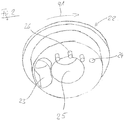
- an end wall 22 is provided, which has a first and a second inlet opening 23, 24 (cf. FIG. 2 ).
- the first inlet opening 23 is designed as an inlet opening for the base paste of a dental impression mass, while the second inlet opening 24 is formed for the catalyst paste of the impression mass. Since the mixing ratio in the illustrated mixer 1 is approximately 5: 1, the first inlet opening 23 is significantly larger than the second inlet opening 24.
- an opening 25 for the passage of the rotor 3 is provided.
- the rotor 3 is connected via a coupling 30 located at the first end 20 of the mixing tube 2 (cf. FIG. 3 ) with a drive element (not shown) coupled.
- the rotor 3 is guided through the opening 25 and also stored in this opening 25.
- the drive element may in particular be part of the output device and drive the rotor 3 in the predetermined direction of rotation 91.
- the rotor 3 has a rotor disk 32 arranged on the rotor hub 31 with driver elements 33 directed towards the end wall 22, wherein the outer ends of the individual carrier elements 33 are bent in the form of blades in the direction of rotation 91 of the rotor 3. Between the individual carrier elements 33, slit-shaped rotor disk openings 34 are provided in the radial direction. On the side facing away from the end wall 22 side of the rotor disk 32 are boom 35th provided on the rotor hub 31, which are aligned with the rotor disk openings 34 substantially.
- mixing elements 36 are provided on the rotor hub 31, the mixing elements 36 being arranged in five mixing element groups 37 in which all associated mixing elements 36 are arranged in a plane perpendicular to the axis 90 of the rotor 3.
- the mixing elements 36 extend - as well as the driving elements 33 and the boom 35 - each of the rotor hub 31 of the rotor 3 to the inner wall 27 of the mixing tube. 2
- pins 26 are provided which project in the direction of the rotor disk 32.
- the area farther in the direction of rotation of the rotor 3 between the second and the first inlet openings 24, 23 is pin-free.
- the pins 26 are all arranged at the same distance from the axis 90 of the rotor 3.
- the entrainment elements 33 on the rotor 3 have recesses 38, through which the pins 26 projecting from the end wall 22 can slide on rotation of the rotor 3. The pins 26 therefore do not hinder the rotation of the rotor 3 about its axis 90.
- the mixer 1 is used for mixing a dental impression material consisting of two components - a base paste and a catalyst paste.
- the two components should be in one Ratio of 5: 1 are mixed, wherein the base paste usually has a significantly higher viscosity than the catalyst paste.
- the dynamic mixer 1 is connected at the first end 20 of the mixing tube 2 with dispensing ports and an output device for the two components of a dental impression material.
- the connection is such that the dispenser pushes the first component - the base paste - through the first inlet port 23 and the second component - the catalyst paste - through the second inlet port 24 into the mixer 1.
- a drive unit of the output device is connected via the coupling 30 with the rotor 3 of the mixer 1 such that the drive unit can drive the rotor 3 in the predetermined direction of rotation 91.
- the dispenser inserts the base paste into the mixer 1 through the first larger inlet port 23. There it is entrained by the entrainment elements 33 of the driven by the drive unit of the output device rotor and conveyed to the pins 26 in the direction of the second smaller inlet opening 24 out. By the pins 26, which can slide through the recesses 38 in the driving elements 33, the base paste is sheared, whereby the viscosity is reduced.
- the catalyst paste is added, which mixes better with it due to the reduction of the viscosity of the base paste.
- the mixture of base paste and catalyst paste which is still rather heterogeneous at this point, then passes through the rotor disk openings 34 past the arms 35 to the mixing elements 36.
- base paste and catalyst paste are further mixed together that emerges at the end of the mixing tube 2, a homogeneous mixture from the outlet opening 21.
- the exiting mixture is homogenized in such a way that it can be used directly as a dental impression material.
- the mixer according to the invention with excellent homogenization neither the temperature nor the extrusion pressure of the components or the mixture is significantly increased compared to other known from the prior art dynamic mixers, so that the predetermined processing times and hardening times of the impression materials are guaranteed.
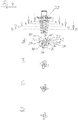
- FIG. 4 Further details of the rotor 3 are shown, wherein the figure next to a side view of the rotor 3 still four sectional views AD includes.
- the mixing elements 36 of the first four mixing element groups 37 seen from the rotor disk 32 are shown in each case.
- Each mixing element group 37 comprises four mixing elements 36, which are distributed uniformly over the circumference of the rotor hub 31.
- front edge 39 is parallel to the rear edge 40.
- the mixing elements 36 each extend to the inner wall 27 of the mixing tube 2, which in FIG. 4A is exemplified by a dashed line.
- mixing element group 37 is provided between two mixing elements 36, a deflecting element 41.
- the deflecting element 41 is arranged between the front edge 39 'of a first mixing element 36 and rear edge 40' of the adjacent mixing element 36. By the deflection element 41, the free area between these two mixing elements 36 is reduced.
- the deflection element 41 does not have to be arranged between two mixing elements 36.
- the deflecting element 41 can also be designed detached from the mixing elements 36.
- the fifth and last mixing element group 37 seen from the rotor disk 32 does not comprise a deflection element 41.
Landscapes
- Chemical & Material Sciences (AREA)
- Chemical Kinetics & Catalysis (AREA)
- Health & Medical Sciences (AREA)
- Dentistry (AREA)
- Epidemiology (AREA)
- Life Sciences & Earth Sciences (AREA)
- Animal Behavior & Ethology (AREA)
- General Health & Medical Sciences (AREA)
- Public Health (AREA)
- Veterinary Medicine (AREA)
- Oral & Maxillofacial Surgery (AREA)
- Engineering & Computer Science (AREA)
- Mechanical Engineering (AREA)
- Mixers Of The Rotary Stirring Type (AREA)
- Dental Tools And Instruments Or Auxiliary Dental Instruments (AREA)
- Dental Preparations (AREA)
Claims (12)
- Mélangeur (1) dynamique pour les composants de masses visqueuses, en particulier pour les composants de masses d'empreintes de dentisterie, avec un tube mélangeur (2) et un rotor (3) qui y est disposé à l'intérieur et qui peut être entraîné, le tube mélangeur (2) présentant à sa première extrémité (20) une paroi frontale (22) avec au moins deux ouvertures d'entrée (23, 24) pour les composants et, à son autre extrémité, une ouverture de sortie (21) pour le mélange, le rotor (3) présentant un disque de rotor (32) avec au moins un élément d'entraînement (33) dirigé vers la paroi frontale (22) et au moins une ouverture de disque de rotor (34) pour le passage des composants vers le côté du disque de rotor (32) éloigné de la paroi frontale (22), au moins un élément de mélange (36) étant disposé sur le moyeu de rotor (31) entre le disque de rotor (32) et l'ouverture de sortie (21) du tube mélangeur (2),
caractérisé en ce
qu'une broche (26) en saillie est disposée sur la paroi frontale (22) en direction du disque de rotor (32), et ce qu'au moins un élément d'entraînement (33) présente au moins un creux (38) pour la broche (26) au moins au nombre de un. - Mélangeur selon la revendication 1,
caractérisé en ce que
la broche (26) au moins au nombre de un présente une longueur qui est égale à au moins 2/3 de la distance entre la paroi frontale (22) et le disque de rotor (32), ou en ce que la broche (26) au moins au nombre de un s'étend jusqu'au disque de rotor (32). - Mélangeur selon l'une des revendications précédentes,
caractérisé en ce que
la hauteur de l'élément d'entraînement (33) au moins au nombre de un du disque de rotor (32) et la longueur de la broche (26) au moins au nombre de un sont essentiellement égales. - Mélangeur selon l'une des revendications précédentes,
caractérisé en ce que
la distance entre la paroi frontale (22) et le disque de rotor (32) est égale à au moins 5 %, de préférence égale à au moins 10 %, plus préférablement est comprise entre 10 et 30 % de la longueur totale du tube mélangeur (2). - Mélangeur selon l'une des revendications précédentes,
caractérisé en ce
qu'il est prévu plus d'une broche (26) sur la paroi frontale (22), les broches (26) ou au moins des groupes de broches (26) étant disposées respectivement à la même distance par rapport à l'axe (90) du rotor (3). - Mélangeur selon l'une des revendications précédentes,
caractérisé en ce que
la broche (26) au moins au nombre de un est, dans le sens de rotation (91) du rotor (3), disposée entre une première ouverture d'entrée (23) plus grande et une deuxième ouverture d'entrée (24) plus petite. - Mélangeur selon l'une des revendications précédentes,
caractérisé en ce que l'extrémité de l'élément d'entraînement (33) au moins au nombre de un qui est éloignée de l'axe (90) du rotor (3) dans le sens de rotation (91) est recourbée. - Mélangeur selon l'une des revendications précédentes,
caractérisé en ce
que l'ouverture de disque de rotor (34) au moins au nombre de un est une fente disposée radialement, au moins un bras (35) en affleurement avec la fente au moins au nombre de un étant disposé de préférence sur le côté du disque de rotor (32) éloigné du côté frontal (22) sur le moyeu de rotor (31). - Mélangeur selon l'une des revendications précédentes,
caractérisé en ce
qu'il est prévu plus d'un élément mélangeur (36), et les éléments mélangeurs (36) sont disposés de préférence dans plusieurs groupes d'éléments mélangeurs (37) espacés dans la direction axiale de l'axe (90) du rotor (3), les éléments mélangeurs (36) d'un groupe d'éléments mélangeurs (37) étant disposés dans un plan perpendiculairement à l'axe (90) du rotor (3). - Mélangeur selon la revendication 9,
caractérisé en ce
qu'un élément de déviation (41) est prévu dans un groupe d'éléments mélangeurs (37), l'élément de déviation (41) étant de préférence une surface de raccordement de deux éléments mélangeurs (36) voisins, et la surface libre entre ces deux éléments mélangeurs (36) étant réduite. - Utilisation d'un mélangeur dynamique selon l'une des revendications 1 à 10 pour des masses d'empreintes de dentisterie.
- Utilisation selon la revendication 11,
caractérisée en ce que
la masse d'empreintes de dentisterie présente une pâte de base en tant que premier composant et une pâte de catalyseur en tant que deuxième composant.
Applications Claiming Priority (2)
| Application Number | Priority Date | Filing Date | Title |
|---|---|---|---|
| DE201320009790 DE202013009790U1 (de) | 2013-12-04 | 2013-12-04 | Dynamischer Mischer |
| PCT/EP2014/076582 WO2015082620A1 (fr) | 2013-12-04 | 2014-12-04 | Mélangeur dynamique et utilisation dudit mélangeur |
Publications (2)
| Publication Number | Publication Date |
|---|---|
| EP3077094A1 EP3077094A1 (fr) | 2016-10-12 |
| EP3077094B1 true EP3077094B1 (fr) | 2017-11-22 |
Family
ID=52023484
Family Applications (1)
| Application Number | Title | Priority Date | Filing Date |
|---|---|---|---|
| EP14811811.0A Active EP3077094B1 (fr) | 2013-12-04 | 2014-12-04 | Mélangeur dynamique et utilisation dudit mélangeur |
Country Status (6)
| Country | Link |
|---|---|
| US (1) | US9943813B2 (fr) |
| EP (1) | EP3077094B1 (fr) |
| KR (1) | KR101713870B1 (fr) |
| CN (1) | CN106061595B (fr) |
| DE (1) | DE202013009790U1 (fr) |
| WO (1) | WO2015082620A1 (fr) |
Families Citing this family (1)
| Publication number | Priority date | Publication date | Assignee | Title |
|---|---|---|---|---|
| DE202013009790U1 (de) * | 2013-12-04 | 2015-03-05 | Mühlbauer Technology Gmbh | Dynamischer Mischer |
Family Cites Families (21)
| Publication number | Priority date | Publication date | Assignee | Title |
|---|---|---|---|---|
| DE3611048C2 (de) | 1986-04-02 | 1997-10-23 | Gyproc Gmbh Baustoffproduktion | Mischer |
| DE3717057A1 (de) | 1987-05-21 | 1988-12-01 | Bayer Ag | Verfahren zur herstellung von isocyanaten |
| DE8717424U1 (de) * | 1987-08-27 | 1988-11-17 | Gurit-Essex Ag, Freienbach | Mischvorrichtung für mindestens zwei Komponenten umfassende Substanzen |
| DE9017323U1 (de) | 1990-12-21 | 1992-04-16 | Thera Patent GmbH & Co KG Gesellschaft für industrielle Schutzrechte, 8031 Seefeld | Dynamischer Mischer |
| US6352177B1 (en) * | 1998-10-14 | 2002-03-05 | Kettenbach Gmbh & Co. Kg | Device for discharging a pasty two-component mixture |
| DE19947331C2 (de) * | 1999-10-01 | 2002-02-28 | 3M Espe Ag | Dynamischer Mischer |
| US6443612B1 (en) * | 1999-12-02 | 2002-09-03 | Wilhelm A. Keller | Dynamic mixer |
| DE59904983D1 (de) | 1999-12-23 | 2003-05-15 | Muehlbauer Ernst Gmbh & Co Kg | Dynamischer Mischer für zahnärztliche Abdruckmassen |
| DE10164385C1 (de) * | 2001-12-28 | 2003-03-06 | Kettenbach Gmbh & Co Kg | Vorrichtung zum Vermischen zweier pastöser Massen, insbesondere zum Vermischen einer Dental-Abformmasse mit einer Katalysatormasse |
| DE20302987U1 (de) * | 2003-02-24 | 2003-04-24 | Ernst Muehlbauer Gmbh & Co Kg | Dynamischer Mischer |
| EP1720664A1 (fr) * | 2004-02-27 | 2006-11-15 | Heraeus Kulzer GmbH | Procede de fabrication de masses de moulage dentaires et dispositifs permettant la mise en oeuvre dudit procede |
| DE102004020410B4 (de) | 2004-04-23 | 2007-08-02 | Heraeus Kulzer Gmbh | Dynamischer Mischer für strukturviskose Pasten |
| PL2190563T3 (pl) * | 2007-09-10 | 2012-02-29 | Sulzer Mixpac Ag | Mieszalnik dynamiczny |
| US7731413B2 (en) * | 2008-02-20 | 2010-06-08 | Zhermack S.P.A. | Mixer for multi-components substance for dental casting |
| KR20100004377U (ko) * | 2008-10-20 | 2010-04-29 | 신봉희 | 치과용 자동혼합기의 팁 |
| JP6010054B2 (ja) * | 2011-02-28 | 2016-10-19 | スルザー ミックスパック アクチェンゲゼルシャフト | ダイナミック・ミキサ |
| JP6077469B2 (ja) * | 2011-02-28 | 2017-02-08 | スルザー ミックスパック アクチェンゲゼルシャフト | ダイナミック・ミキサ |
| US8365462B2 (en) | 2011-05-31 | 2013-02-05 | Heliae Development, Llc | V-Trough photobioreactor systems |
| KR101091062B1 (ko) | 2011-07-04 | 2011-12-08 | (주) 세일덴텍 | 자동형 치과인상재 혼합 믹싱팁 |
| DE202013009790U1 (de) * | 2013-12-04 | 2015-03-05 | Mühlbauer Technology Gmbh | Dynamischer Mischer |
| KR20150078712A (ko) * | 2013-12-31 | 2015-07-08 | 김인자 | 치과 치료용 인상재의 믹싱팁 구조 |
-
2013
- 2013-12-04 DE DE201320009790 patent/DE202013009790U1/de not_active Expired - Lifetime
-
2014
- 2014-12-04 CN CN201480065721.9A patent/CN106061595B/zh active Active
- 2014-12-04 WO PCT/EP2014/076582 patent/WO2015082620A1/fr not_active Ceased
- 2014-12-04 EP EP14811811.0A patent/EP3077094B1/fr active Active
- 2014-12-04 US US15/038,170 patent/US9943813B2/en active Active
- 2014-12-04 KR KR1020167014348A patent/KR101713870B1/ko active Active
Also Published As
| Publication number | Publication date |
|---|---|
| CN106061595A (zh) | 2016-10-26 |
| KR20160098207A (ko) | 2016-08-18 |
| US9943813B2 (en) | 2018-04-17 |
| KR101713870B1 (ko) | 2017-03-09 |
| WO2015082620A1 (fr) | 2015-06-11 |
| US20160288066A1 (en) | 2016-10-06 |
| CN106061595B (zh) | 2018-10-02 |
| DE202013009790U1 (de) | 2015-03-05 |
| EP3077094A1 (fr) | 2016-10-12 |
Similar Documents
| Publication | Publication Date | Title |
|---|---|---|
| EP1110599B1 (fr) | Mélangeur dynamique pour compositions pour empreintes dentaires | |
| DE10112904B4 (de) | Dynamischer Mischer und Verfahren zum Mischen von mindestens zwei Pastenkomponenten | |
| EP1099470B1 (fr) | Dispositif pour mélanger deux matières pâteuses, en particulier pour mélanger une matière pour empreinte dentaire avec une matière de calalyse | |
| DE19947331C2 (de) | Dynamischer Mischer | |
| DE69716887T2 (de) | Mischer | |
| EP1029585B1 (fr) | Dispositif pour délivrer une substance formée d'un mélange de plusieurs composants, utilisé notamment en dentisterie | |
| EP1458467A1 (fr) | Dispositif pour melanger deux matieres pateuses, notamment pour melanger une matiere pour empreinte dentaire avec une matiere catalytique | |
| EP2680959B1 (fr) | Mélangeur dynamique et son utilisation | |
| CH699191A1 (de) | Austraganordnung mit Einzelspritzen und Spritzenhalter. | |
| WO2000021652A1 (fr) | Dispositif pour melanger deux matieres pateuses, en particulier pour melanger une matiere pour empreinte dentaire avec une matiere de catalyse | |
| EP0378806A2 (fr) | Dispositif de mélange et de distribution de produits pâteux | |
| EP0232733A2 (fr) | Dispositif pour appliquer un fluide à deux composants | |
| EP2885087B1 (fr) | Dispositif de sortie | |
| DE20302987U1 (de) | Dynamischer Mischer | |
| EP2548635A1 (fr) | Mélangeur dynamique doté d'un joint | |
| EP3658265B1 (fr) | Melangeur | |
| EP2258468B1 (fr) | Système de mélange pour cartouche à deux composants | |
| EP3077094B1 (fr) | Mélangeur dynamique et utilisation dudit mélangeur | |
| DE102004051063A1 (de) | Innenmischer zum Kneten von plastischen Massen | |
| EP1595594B1 (fr) | Mélangeur dynamique | |
| DE102017117198A1 (de) | Mischer | |
| DE102013103552A1 (de) | Spritze | |
| EP2258466A1 (fr) | Système de mélange pour cartouche à deux composants | |
| DE202009007919U1 (de) | Mischsystem für Zweikomponentenkartusche | |
| EP1720664A1 (fr) | Procede de fabrication de masses de moulage dentaires et dispositifs permettant la mise en oeuvre dudit procede |
Legal Events
| Date | Code | Title | Description |
|---|---|---|---|
| PUAI | Public reference made under article 153(3) epc to a published international application that has entered the european phase |
Free format text: ORIGINAL CODE: 0009012 |
|
| 17P | Request for examination filed |
Effective date: 20160701 |
|
| AK | Designated contracting states |
Kind code of ref document: A1 Designated state(s): AL AT BE BG CH CY CZ DE DK EE ES FI FR GB GR HR HU IE IS IT LI LT LU LV MC MK MT NL NO PL PT RO RS SE SI SK SM TR |
|
| AX | Request for extension of the european patent |
Extension state: BA ME |
|
| RIN1 | Information on inventor provided before grant (corrected) |
Inventor name: LAMOTT, KARSTEN |
|
| DAX | Request for extension of the european patent (deleted) | ||
| REG | Reference to a national code |
Ref country code: DE Ref legal event code: R079 Ref document number: 502014006358 Country of ref document: DE Free format text: PREVIOUS MAIN CLASS: B01F0013000000 Ipc: B01F0007000000 |
|
| GRAP | Despatch of communication of intention to grant a patent |
Free format text: ORIGINAL CODE: EPIDOSNIGR1 |
|
| STAA | Information on the status of an ep patent application or granted ep patent |
Free format text: STATUS: GRANT OF PATENT IS INTENDED |
|
| RIC1 | Information provided on ipc code assigned before grant |
Ipc: A61C 9/00 20060101ALI20170703BHEP Ipc: B01F 7/00 20060101AFI20170703BHEP Ipc: B05C 17/005 20060101ALI20170703BHEP Ipc: B01F 13/00 20060101ALI20170703BHEP |
|
| INTG | Intention to grant announced |
Effective date: 20170720 |
|
| GRAS | Grant fee paid |
Free format text: ORIGINAL CODE: EPIDOSNIGR3 |
|
| GRAA | (expected) grant |
Free format text: ORIGINAL CODE: 0009210 |
|
| STAA | Information on the status of an ep patent application or granted ep patent |
Free format text: STATUS: THE PATENT HAS BEEN GRANTED |
|
| AK | Designated contracting states |
Kind code of ref document: B1 Designated state(s): AL AT BE BG CH CY CZ DE DK EE ES FI FR GB GR HR HU IE IS IT LI LT LU LV MC MK MT NL NO PL PT RO RS SE SI SK SM TR |
|
| REG | Reference to a national code |
Ref country code: GB Ref legal event code: FG4D Free format text: NOT ENGLISH |
|
| REG | Reference to a national code |
Ref country code: CH Ref legal event code: EP |
|
| REG | Reference to a national code |
Ref country code: IE Ref legal event code: FG4D Free format text: LANGUAGE OF EP DOCUMENT: GERMAN |
|
| REG | Reference to a national code |
Ref country code: AT Ref legal event code: REF Ref document number: 947898 Country of ref document: AT Kind code of ref document: T Effective date: 20171215 |
|
| REG | Reference to a national code |
Ref country code: DE Ref legal event code: R096 Ref document number: 502014006358 Country of ref document: DE Ref country code: FR Ref legal event code: PLFP Year of fee payment: 4 |
|
| REG | Reference to a national code |
Ref country code: CH Ref legal event code: NV Representative=s name: TROESCH SCHEIDEGGER WERNER AG, CH |
|
| REG | Reference to a national code |
Ref country code: NL Ref legal event code: MP Effective date: 20171122 |
|
| REG | Reference to a national code |
Ref country code: LT Ref legal event code: MG4D |
|
| PG25 | Lapsed in a contracting state [announced via postgrant information from national office to epo] |
Ref country code: NO Free format text: LAPSE BECAUSE OF FAILURE TO SUBMIT A TRANSLATION OF THE DESCRIPTION OR TO PAY THE FEE WITHIN THE PRESCRIBED TIME-LIMIT Effective date: 20180222 Ref country code: FI Free format text: LAPSE BECAUSE OF FAILURE TO SUBMIT A TRANSLATION OF THE DESCRIPTION OR TO PAY THE FEE WITHIN THE PRESCRIBED TIME-LIMIT Effective date: 20171122 Ref country code: ES Free format text: LAPSE BECAUSE OF FAILURE TO SUBMIT A TRANSLATION OF THE DESCRIPTION OR TO PAY THE FEE WITHIN THE PRESCRIBED TIME-LIMIT Effective date: 20171122 Ref country code: SE Free format text: LAPSE BECAUSE OF FAILURE TO SUBMIT A TRANSLATION OF THE DESCRIPTION OR TO PAY THE FEE WITHIN THE PRESCRIBED TIME-LIMIT Effective date: 20171122 Ref country code: LT Free format text: LAPSE BECAUSE OF FAILURE TO SUBMIT A TRANSLATION OF THE DESCRIPTION OR TO PAY THE FEE WITHIN THE PRESCRIBED TIME-LIMIT Effective date: 20171122 Ref country code: NL Free format text: LAPSE BECAUSE OF FAILURE TO SUBMIT A TRANSLATION OF THE DESCRIPTION OR TO PAY THE FEE WITHIN THE PRESCRIBED TIME-LIMIT Effective date: 20171122 |
|
| PG25 | Lapsed in a contracting state [announced via postgrant information from national office to epo] |
Ref country code: LV Free format text: LAPSE BECAUSE OF FAILURE TO SUBMIT A TRANSLATION OF THE DESCRIPTION OR TO PAY THE FEE WITHIN THE PRESCRIBED TIME-LIMIT Effective date: 20171122 Ref country code: HR Free format text: LAPSE BECAUSE OF FAILURE TO SUBMIT A TRANSLATION OF THE DESCRIPTION OR TO PAY THE FEE WITHIN THE PRESCRIBED TIME-LIMIT Effective date: 20171122 Ref country code: BG Free format text: LAPSE BECAUSE OF FAILURE TO SUBMIT A TRANSLATION OF THE DESCRIPTION OR TO PAY THE FEE WITHIN THE PRESCRIBED TIME-LIMIT Effective date: 20180222 Ref country code: GR Free format text: LAPSE BECAUSE OF FAILURE TO SUBMIT A TRANSLATION OF THE DESCRIPTION OR TO PAY THE FEE WITHIN THE PRESCRIBED TIME-LIMIT Effective date: 20180223 Ref country code: RS Free format text: LAPSE BECAUSE OF FAILURE TO SUBMIT A TRANSLATION OF THE DESCRIPTION OR TO PAY THE FEE WITHIN THE PRESCRIBED TIME-LIMIT Effective date: 20171122 |
|
| PG25 | Lapsed in a contracting state [announced via postgrant information from national office to epo] |
Ref country code: CZ Free format text: LAPSE BECAUSE OF FAILURE TO SUBMIT A TRANSLATION OF THE DESCRIPTION OR TO PAY THE FEE WITHIN THE PRESCRIBED TIME-LIMIT Effective date: 20171122 Ref country code: SK Free format text: LAPSE BECAUSE OF FAILURE TO SUBMIT A TRANSLATION OF THE DESCRIPTION OR TO PAY THE FEE WITHIN THE PRESCRIBED TIME-LIMIT Effective date: 20171122 Ref country code: EE Free format text: LAPSE BECAUSE OF FAILURE TO SUBMIT A TRANSLATION OF THE DESCRIPTION OR TO PAY THE FEE WITHIN THE PRESCRIBED TIME-LIMIT Effective date: 20171122 Ref country code: CY Free format text: LAPSE BECAUSE OF FAILURE TO SUBMIT A TRANSLATION OF THE DESCRIPTION OR TO PAY THE FEE WITHIN THE PRESCRIBED TIME-LIMIT Effective date: 20171122 Ref country code: DK Free format text: LAPSE BECAUSE OF FAILURE TO SUBMIT A TRANSLATION OF THE DESCRIPTION OR TO PAY THE FEE WITHIN THE PRESCRIBED TIME-LIMIT Effective date: 20171122 |
|
| REG | Reference to a national code |
Ref country code: DE Ref legal event code: R097 Ref document number: 502014006358 Country of ref document: DE |
|
| PG25 | Lapsed in a contracting state [announced via postgrant information from national office to epo] |
Ref country code: PL Free format text: LAPSE BECAUSE OF FAILURE TO SUBMIT A TRANSLATION OF THE DESCRIPTION OR TO PAY THE FEE WITHIN THE PRESCRIBED TIME-LIMIT Effective date: 20171122 Ref country code: SM Free format text: LAPSE BECAUSE OF FAILURE TO SUBMIT A TRANSLATION OF THE DESCRIPTION OR TO PAY THE FEE WITHIN THE PRESCRIBED TIME-LIMIT Effective date: 20171122 Ref country code: IT Free format text: LAPSE BECAUSE OF FAILURE TO SUBMIT A TRANSLATION OF THE DESCRIPTION OR TO PAY THE FEE WITHIN THE PRESCRIBED TIME-LIMIT Effective date: 20171122 |
|
| REG | Reference to a national code |
Ref country code: IE Ref legal event code: MM4A |
|
| PG25 | Lapsed in a contracting state [announced via postgrant information from national office to epo] |
Ref country code: MT Free format text: LAPSE BECAUSE OF FAILURE TO SUBMIT A TRANSLATION OF THE DESCRIPTION OR TO PAY THE FEE WITHIN THE PRESCRIBED TIME-LIMIT Effective date: 20171122 Ref country code: LU Free format text: LAPSE BECAUSE OF NON-PAYMENT OF DUE FEES Effective date: 20171204 |
|
| PLBE | No opposition filed within time limit |
Free format text: ORIGINAL CODE: 0009261 |
|
| STAA | Information on the status of an ep patent application or granted ep patent |
Free format text: STATUS: NO OPPOSITION FILED WITHIN TIME LIMIT |
|
| REG | Reference to a national code |
Ref country code: BE Ref legal event code: MM Effective date: 20171231 |
|
| 26N | No opposition filed |
Effective date: 20180823 |
|
| PG25 | Lapsed in a contracting state [announced via postgrant information from national office to epo] |
Ref country code: IE Free format text: LAPSE BECAUSE OF NON-PAYMENT OF DUE FEES Effective date: 20171204 |
|
| PG25 | Lapsed in a contracting state [announced via postgrant information from national office to epo] |
Ref country code: SI Free format text: LAPSE BECAUSE OF FAILURE TO SUBMIT A TRANSLATION OF THE DESCRIPTION OR TO PAY THE FEE WITHIN THE PRESCRIBED TIME-LIMIT Effective date: 20171122 Ref country code: BE Free format text: LAPSE BECAUSE OF NON-PAYMENT OF DUE FEES Effective date: 20171231 |
|
| PG25 | Lapsed in a contracting state [announced via postgrant information from national office to epo] |
Ref country code: MC Free format text: LAPSE BECAUSE OF FAILURE TO SUBMIT A TRANSLATION OF THE DESCRIPTION OR TO PAY THE FEE WITHIN THE PRESCRIBED TIME-LIMIT Effective date: 20171122 Ref country code: HU Free format text: LAPSE BECAUSE OF FAILURE TO SUBMIT A TRANSLATION OF THE DESCRIPTION OR TO PAY THE FEE WITHIN THE PRESCRIBED TIME-LIMIT; INVALID AB INITIO Effective date: 20141204 |
|
| PG25 | Lapsed in a contracting state [announced via postgrant information from national office to epo] |
Ref country code: RO Free format text: LAPSE BECAUSE OF FAILURE TO SUBMIT A TRANSLATION OF THE DESCRIPTION OR TO PAY THE FEE WITHIN THE PRESCRIBED TIME-LIMIT Effective date: 20171122 |
|
| PG25 | Lapsed in a contracting state [announced via postgrant information from national office to epo] |
Ref country code: MK Free format text: LAPSE BECAUSE OF FAILURE TO SUBMIT A TRANSLATION OF THE DESCRIPTION OR TO PAY THE FEE WITHIN THE PRESCRIBED TIME-LIMIT Effective date: 20171122 |
|
| PG25 | Lapsed in a contracting state [announced via postgrant information from national office to epo] |
Ref country code: TR Free format text: LAPSE BECAUSE OF FAILURE TO SUBMIT A TRANSLATION OF THE DESCRIPTION OR TO PAY THE FEE WITHIN THE PRESCRIBED TIME-LIMIT Effective date: 20171122 |
|
| PG25 | Lapsed in a contracting state [announced via postgrant information from national office to epo] |
Ref country code: PT Free format text: LAPSE BECAUSE OF FAILURE TO SUBMIT A TRANSLATION OF THE DESCRIPTION OR TO PAY THE FEE WITHIN THE PRESCRIBED TIME-LIMIT Effective date: 20171122 |
|
| PG25 | Lapsed in a contracting state [announced via postgrant information from national office to epo] |
Ref country code: AL Free format text: LAPSE BECAUSE OF FAILURE TO SUBMIT A TRANSLATION OF THE DESCRIPTION OR TO PAY THE FEE WITHIN THE PRESCRIBED TIME-LIMIT Effective date: 20171122 Ref country code: IS Free format text: LAPSE BECAUSE OF FAILURE TO SUBMIT A TRANSLATION OF THE DESCRIPTION OR TO PAY THE FEE WITHIN THE PRESCRIBED TIME-LIMIT Effective date: 20180322 |
|
| REG | Reference to a national code |
Ref country code: AT Ref legal event code: MM01 Ref document number: 947898 Country of ref document: AT Kind code of ref document: T Effective date: 20191204 |
|
| PG25 | Lapsed in a contracting state [announced via postgrant information from national office to epo] |
Ref country code: AT Free format text: LAPSE BECAUSE OF NON-PAYMENT OF DUE FEES Effective date: 20191204 |
|
| REG | Reference to a national code |
Ref country code: DE Ref legal event code: R079 Ref document number: 502014006358 Country of ref document: DE Free format text: PREVIOUS MAIN CLASS: B01F0007000000 Ipc: B01F0027000000 |
|
| P01 | Opt-out of the competence of the unified patent court (upc) registered |
Effective date: 20230516 |
|
| PGFP | Annual fee paid to national office [announced via postgrant information from national office to epo] |
Ref country code: CH Payment date: 20250101 Year of fee payment: 11 |
|
| REG | Reference to a national code |
Ref country code: CH Ref legal event code: U11 Free format text: ST27 STATUS EVENT CODE: U-0-0-U10-U11 (AS PROVIDED BY THE NATIONAL OFFICE) Effective date: 20260101 |
|
| PGFP | Annual fee paid to national office [announced via postgrant information from national office to epo] |
Ref country code: DE Payment date: 20251218 Year of fee payment: 12 |
|
| PGFP | Annual fee paid to national office [announced via postgrant information from national office to epo] |
Ref country code: GB Payment date: 20251218 Year of fee payment: 12 |
|
| PGFP | Annual fee paid to national office [announced via postgrant information from national office to epo] |
Ref country code: FR Payment date: 20251218 Year of fee payment: 12 |