EP3077180B1 - Procédé de production accélérée d'objets par fabrication générative - Google Patents
Procédé de production accélérée d'objets par fabrication générative Download PDFInfo
- Publication number
- EP3077180B1 EP3077180B1 EP14811793.0A EP14811793A EP3077180B1 EP 3077180 B1 EP3077180 B1 EP 3077180B1 EP 14811793 A EP14811793 A EP 14811793A EP 3077180 B1 EP3077180 B1 EP 3077180B1
- Authority
- EP
- European Patent Office
- Prior art keywords
- layer
- solidification
- powder
- radiation
- solidified
- Prior art date
- Legal status (The legal status is an assumption and is not a legal conclusion. Google has not performed a legal analysis and makes no representation as to the accuracy of the status listed.)
- Active
Links
Images


Classifications
-
- B—PERFORMING OPERATIONS; TRANSPORTING
- B29—WORKING OF PLASTICS; WORKING OF SUBSTANCES IN A PLASTIC STATE IN GENERAL
- B29C—SHAPING OR JOINING OF PLASTICS; SHAPING OF MATERIAL IN A PLASTIC STATE, NOT OTHERWISE PROVIDED FOR; AFTER-TREATMENT OF THE SHAPED PRODUCTS, e.g. REPAIRING
- B29C64/00—Additive manufacturing, i.e. manufacturing of three-dimensional [3D] objects by additive deposition, additive agglomeration or additive layering, e.g. by 3D printing, stereolithography or selective laser sintering
- B29C64/10—Processes of additive manufacturing
- B29C64/141—Processes of additive manufacturing using only solid materials
- B29C64/153—Processes of additive manufacturing using only solid materials using layers of powder being selectively joined, e.g. by selective laser sintering or melting
-
- B—PERFORMING OPERATIONS; TRANSPORTING
- B22—CASTING; POWDER METALLURGY
- B22F—WORKING METALLIC POWDER; MANUFACTURE OF ARTICLES FROM METALLIC POWDER; MAKING METALLIC POWDER; APPARATUS OR DEVICES SPECIALLY ADAPTED FOR METALLIC POWDER
- B22F10/00—Additive manufacturing of workpieces or articles from metallic powder
-
- B—PERFORMING OPERATIONS; TRANSPORTING
- B22—CASTING; POWDER METALLURGY
- B22F—WORKING METALLIC POWDER; MANUFACTURE OF ARTICLES FROM METALLIC POWDER; MAKING METALLIC POWDER; APPARATUS OR DEVICES SPECIALLY ADAPTED FOR METALLIC POWDER
- B22F10/00—Additive manufacturing of workpieces or articles from metallic powder
- B22F10/20—Direct sintering or melting
- B22F10/28—Powder bed fusion, e.g. selective laser melting [SLM] or electron beam melting [EBM]
-
- B—PERFORMING OPERATIONS; TRANSPORTING
- B22—CASTING; POWDER METALLURGY
- B22F—WORKING METALLIC POWDER; MANUFACTURE OF ARTICLES FROM METALLIC POWDER; MAKING METALLIC POWDER; APPARATUS OR DEVICES SPECIALLY ADAPTED FOR METALLIC POWDER
- B22F10/00—Additive manufacturing of workpieces or articles from metallic powder
- B22F10/30—Process control
- B22F10/36—Process control of energy beam parameters
-
- B—PERFORMING OPERATIONS; TRANSPORTING
- B22—CASTING; POWDER METALLURGY
- B22F—WORKING METALLIC POWDER; MANUFACTURE OF ARTICLES FROM METALLIC POWDER; MAKING METALLIC POWDER; APPARATUS OR DEVICES SPECIALLY ADAPTED FOR METALLIC POWDER
- B22F12/00—Apparatus or devices specially adapted for additive manufacturing; Auxiliary means for additive manufacturing; Combinations of additive manufacturing apparatus or devices with other processing apparatus or devices
- B22F12/10—Auxiliary heating means
- B22F12/13—Auxiliary heating means to preheat the material
-
- B—PERFORMING OPERATIONS; TRANSPORTING
- B28—WORKING CEMENT, CLAY, OR STONE
- B28B—SHAPING CLAY OR OTHER CERAMIC COMPOSITIONS; SHAPING SLAG; SHAPING MIXTURES CONTAINING CEMENTITIOUS MATERIAL, e.g. PLASTER
- B28B1/00—Producing shaped prefabricated articles from the material
- B28B1/001—Rapid manufacturing of 3D objects by additive depositing, agglomerating or laminating of material
-
- B—PERFORMING OPERATIONS; TRANSPORTING
- B28—WORKING CEMENT, CLAY, OR STONE
- B28B—SHAPING CLAY OR OTHER CERAMIC COMPOSITIONS; SHAPING SLAG; SHAPING MIXTURES CONTAINING CEMENTITIOUS MATERIAL, e.g. PLASTER
- B28B17/00—Details of, or accessories for, apparatus for shaping the material; Auxiliary measures taken in connection with such shaping
- B28B17/0063—Control arrangements
- B28B17/0081—Process control
-
- B—PERFORMING OPERATIONS; TRANSPORTING
- B29—WORKING OF PLASTICS; WORKING OF SUBSTANCES IN A PLASTIC STATE IN GENERAL
- B29C—SHAPING OR JOINING OF PLASTICS; SHAPING OF MATERIAL IN A PLASTIC STATE, NOT OTHERWISE PROVIDED FOR; AFTER-TREATMENT OF THE SHAPED PRODUCTS, e.g. REPAIRING
- B29C64/00—Additive manufacturing, i.e. manufacturing of three-dimensional [3D] objects by additive deposition, additive agglomeration or additive layering, e.g. by 3D printing, stereolithography or selective laser sintering
- B29C64/30—Auxiliary operations or equipment
- B29C64/386—Data acquisition or data processing for additive manufacturing
- B29C64/393—Data acquisition or data processing for additive manufacturing for controlling or regulating additive manufacturing processes
-
- B—PERFORMING OPERATIONS; TRANSPORTING
- B29—WORKING OF PLASTICS; WORKING OF SUBSTANCES IN A PLASTIC STATE IN GENERAL
- B29C—SHAPING OR JOINING OF PLASTICS; SHAPING OF MATERIAL IN A PLASTIC STATE, NOT OTHERWISE PROVIDED FOR; AFTER-TREATMENT OF THE SHAPED PRODUCTS, e.g. REPAIRING
- B29C64/00—Additive manufacturing, i.e. manufacturing of three-dimensional [3D] objects by additive deposition, additive agglomeration or additive layering, e.g. by 3D printing, stereolithography or selective laser sintering
- B29C64/40—Structures for supporting 3D objects during manufacture and intended to be sacrificed after completion thereof
-
- B—PERFORMING OPERATIONS; TRANSPORTING
- B33—ADDITIVE MANUFACTURING TECHNOLOGY
- B33Y—ADDITIVE MANUFACTURING, i.e. MANUFACTURING OF THREE-DIMENSIONAL [3D] OBJECTS BY ADDITIVE DEPOSITION, ADDITIVE AGGLOMERATION OR ADDITIVE LAYERING, e.g. BY 3D PRINTING, STEREOLITHOGRAPHY OR SELECTIVE LASER SINTERING
- B33Y10/00—Processes of additive manufacturing
-
- B—PERFORMING OPERATIONS; TRANSPORTING
- B33—ADDITIVE MANUFACTURING TECHNOLOGY
- B33Y—ADDITIVE MANUFACTURING, i.e. MANUFACTURING OF THREE-DIMENSIONAL [3D] OBJECTS BY ADDITIVE DEPOSITION, ADDITIVE AGGLOMERATION OR ADDITIVE LAYERING, e.g. BY 3D PRINTING, STEREOLITHOGRAPHY OR SELECTIVE LASER SINTERING
- B33Y30/00—Apparatus for additive manufacturing; Details thereof or accessories therefor
-
- B—PERFORMING OPERATIONS; TRANSPORTING
- B22—CASTING; POWDER METALLURGY
- B22F—WORKING METALLIC POWDER; MANUFACTURE OF ARTICLES FROM METALLIC POWDER; MAKING METALLIC POWDER; APPARATUS OR DEVICES SPECIALLY ADAPTED FOR METALLIC POWDER
- B22F12/00—Apparatus or devices specially adapted for additive manufacturing; Auxiliary means for additive manufacturing; Combinations of additive manufacturing apparatus or devices with other processing apparatus or devices
- B22F12/90—Means for process control, e.g. cameras or sensors
-
- B—PERFORMING OPERATIONS; TRANSPORTING
- B33—ADDITIVE MANUFACTURING TECHNOLOGY
- B33Y—ADDITIVE MANUFACTURING, i.e. MANUFACTURING OF THREE-DIMENSIONAL [3D] OBJECTS BY ADDITIVE DEPOSITION, ADDITIVE AGGLOMERATION OR ADDITIVE LAYERING, e.g. BY 3D PRINTING, STEREOLITHOGRAPHY OR SELECTIVE LASER SINTERING
- B33Y50/00—Data acquisition or data processing for additive manufacturing
- B33Y50/02—Data acquisition or data processing for additive manufacturing for controlling or regulating additive manufacturing processes
-
- Y—GENERAL TAGGING OF NEW TECHNOLOGICAL DEVELOPMENTS; GENERAL TAGGING OF CROSS-SECTIONAL TECHNOLOGIES SPANNING OVER SEVERAL SECTIONS OF THE IPC; TECHNICAL SUBJECTS COVERED BY FORMER USPC CROSS-REFERENCE ART COLLECTIONS [XRACs] AND DIGESTS
- Y02—TECHNOLOGIES OR APPLICATIONS FOR MITIGATION OR ADAPTATION AGAINST CLIMATE CHANGE
- Y02P—CLIMATE CHANGE MITIGATION TECHNOLOGIES IN THE PRODUCTION OR PROCESSING OF GOODS
- Y02P10/00—Technologies related to metal processing
- Y02P10/25—Process efficiency
Definitions
- the present invention relates to a method for building up three-dimensional objects in layers by means of additive manufacturing and an associated device.
- the present invention relates to such a method and apparatus, by means of which the manufacturing time is reduced.
- Methods for the layer-by-layer generative production of three-dimensional objects are for example in EP 1 486 317 B1 described. If a powder is used as the starting material for production, which is sintered or melted by introducing thermal energy, the construction process normally proceeds in such a way that a CAD model of the object to be produced is made, which is broken down into layers, and then the Building material is solidified in layers according to cross sections of the CAD model.
- the construction process proceeds as follows: After a powdery layer of building material has been applied to an already solidified layer, the newly applied powder layer is first preheated by means of radiant heating to a working temperature below the temperature at which it is solidified. Radiation (such as a laser beam) is then directed onto the preheated layer to selectively solidify the building material. After all layers of the object have been made, it is allowed to cool and the object is removed from the unsolidified powder that surrounds the object.
- radiant heating such as a laser beam
- the manufacturing method just outlined is primarily used for the rapid manufacture of prototypes or models.
- the advantage of the method for prototype or model production is that the method allows the production of a wide range of prototypes or models without the need to produce production tools beforehand that are adapted to the type of model to be produced are. Compared to a conventional method, the prototype or model can therefore be produced in a relatively short time, which is why the term "rapid prototyping" is also used for this type of method.
- FR 2 878 771 A1 describes a laser sintering process in which a layer to be solidified is irradiated in several passes by means of a laser beam at points to be solidified.
- the powder material should be kept at or near the melting point during the repeated irradiation processes. In particular it is also contemplated to perform the repeated irradiation processes with lower laser energy.
- WO 2012/102655 A1 also describes a sintering or melting process in which an energy beam irradiates selected areas of layers to produce an object. The temperature conditions in the layer to be irradiated are calculated and the beam energy is adapted to the result of the calculation.
- US 2007/196561 A1 describes a method for moving the measuring range of a temperature measuring device which measures the temperature of a layer to be selectively solidified by means of laser radiation in a laser sintering device.
- the position of the temperature measurement area on the layer can be set independently of the position of the consolidation beam on the layer. This can prevent the temperature from being falsified by the fact that the laser radiation increases the temperature in the temperature measuring range.
- EP 1 896 246 B1 already approaches to accelerate proceedings.
- EP 1 896 246 B1 an interchangeable container is presented in which the object is manufactured and which can be removed from the manufacturing device after the manufacturing process has been completed so that cooling takes place outside the manufacturing device and the manufacturing device is immediately available again for a new manufacturing process.
- the invention is based on the idea that the time required to preheat a freshly applied powder layer to the working temperature can be reduced if one makes use of the fact that the powder layer can warm up further during the exposure process.
- Preheating temperature working temperature deviates. If the powder material is too cool during solidification, only incomplete solidification takes place, which, for example, reduces the elongation at break of the objects perpendicular to the layers (in the z-direction).
- the preheating temperature is too low, the dimensions of the components are smaller than the target dimensions, since a smaller proportion of the powder surrounding the object to be produced is also solidified in the edge area of the object.
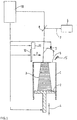
- Fig. 1 the structure of a device according to the invention for producing three-dimensional objects by means of a generative layer construction method is first described.
- the object 3 to be produced is produced in layers on a construction base 2.
- the construction base 2 forms the floor and a frame 1 forms the side walls of an upwardly open container in which the construction process takes place.
- the construction base 2 is connected to a lifting mechanism 4 which can move the construction base in the vertical direction.
- the upper end of the frame 1 encloses a construction field 5 in which the consolidation takes place.
- a coater 11 for applying a layer of a powder material in the construction field is arranged above the construction field 5. All powders that can be solidified by means of heat input can be used as powder material, for example polymer powder, metal powder, ceramic powder or even composite powder composed of different types of materials. Furthermore, fillers and / or additives can also be added to the powders.
- the Fig. 1 furthermore shows schematically an application device 12 which can be moved in the horizontal direction and serves to smooth an applied powder layer. Furthermore, an irradiation device in the form of a laser 6 is provided, which generates a laser beam 7 which can be directed by a deflection device 8 onto any points in the construction field 5. By the action of the laser beam 7 on the powder material in the construction field, the powder material can be selectively heated so that it solidifies as a result at those points which correspond to a cross section of the object 3 to be produced.
- the device according to the invention contains a heating device 9 above the construction field 5, which preheats a newly applied powder layer to a working temperature below a temperature at which the solidification of the powder material takes place.
- the heating device (9) is preferably a radiant heater (for example one or more radiant heaters) which, by emitting electromagnetic radiation, can introduce thermal energy into the newly applied powder layer over a large area.
- Reference numeral 10 denotes a control device which is connected to the laser 6, the deflection device 8, the application device 11, the application device 12 and the lifting mechanism 4 and controls the construction process.
- a housing which surrounds the frame 1, the lifting mechanism 4, the laser 6, the deflection device 8, the application device 11 and the application device 12 is not shown.
- the construction base 2 is moved by means of the lifting mechanism 4 into a position in which the upper side of the construction base 2 or a construction platform arranged on it lies just below the upper edge of the frame 1.
- the powder material applied by the coater 11 is then distributed homogeneously on the construction base 2 or the construction platform by means of the application device 12.
- the initially set vertical distance to the upper edge of the frame 1 defines the thickness of the applied layer.
- a waiting time is inserted, within which the applied powder layer by means of the heating device 9 to a working temperature below a temperature at which the building material is affected by the action of the laser beam is solidified, is preheated.
- the heating device 9 is also preferably connected to the control device 10.
- the temperature of the preheated building material layer is preferably controlled by means of a temperature measuring device 14.
- the temperature measuring device 14 can be a pyrometer which measures the surface temperature of the applied layer in an area of the construction field 5, the area should, if possible, be outside the object 3 during the entire production of the object 3.
- the powder layer is solidified in its region corresponding to the cross section of the object by the input of thermal energy by means of the laser beam.
- the building base 2 is again lowered by the amount of a layer thickness of the building material, building material is again applied, preheated, selectively solidified, etc. until the manufacturing process of the object is completed.
- the solidification is started before the applied powder layer has reached the desired working temperature. If, for example, the working temperature is approx. 175 ° C, solidification is started according to the invention when the powder layer temperature is still approx. 2 ° C degrees below the working temperature. In this case, however, more heat energy per unit area is introduced per unit area during a predetermined period of time from the beginning of the directing of the laser beam 7 onto the locations of the construction field 5 lying within the object cross-section in order to compensate for the too low powder layer temperature.
- the control device 10 varies the power density and / or deflection speed of the laser beam 7 while it sweeps over the locations of the construction field corresponding to the cross section.
- the thermal energy introduced into the material by the laser beam 7 per unit area is continuously reduced, since further thermal energy is continuously introduced into the powder layer by the heating device 9 during the predetermined period of time.
- the function f (t) can be explicitly described by a polynomial or by means of a table stored function values f (t), which change as a function of time.
- the time is the time that has elapsed since the beginning of the exposure process of a layer.
- the value ⁇ 0 is a certain basic light output, the value of which can be selected as desired because the size of f can be adapted to the choice of ⁇ 0 (by multiplying f by a constant factor).
- the thermal energy introduced by the laser per unit area is then kept constant for the remainder of the exposure time, even if this does not necessarily have to be the case for the present invention.
- the function that the heat input per unit area follows during the predetermined period of time can be determined empirically by means of preliminary tests on components or test specimens. A method for obtaining such a function is described below: First, in the generative layer building device (for example the device from Fig. 1 ) Objects (e.g. tension rods according to ISO 527) produced in a test run. For this purpose, groups of five tension rods, for example, are produced in such a way that the groups are exposed at different times from the beginning of the exposure of a layer. For example, after the solidification process, a waiting time (for example 2 seconds) is inserted for one group before the next group is exposed. The exposure process is started before the desired working temperature is reached, that is, as in the production of the actual objects, for example already when the temperature measuring device 14 shows a value, for example approx. 2 ° C. below the desired working temperature.
- Objects e.g. tension rods according to ISO 5257
- the temperature of the test objects e.g. groups of tension rods located at different points in the installation space is not influenced by the position in the installation space, for example if the heat dissipation into the surroundings of the installation space is greater in an edge location than in a Location in the center of the installation space.
- the mechanical properties of the tension rods are then measured in accordance with DIN 527-1 and DIN-ISO 527-2 Type 1B, with mean values being formed for each group. Due to the different exposure times for the different groups of tension rods, the applied powder layer for the respective tension rod groups has been preheated to different temperatures in such a preliminary test when solidification with the laser beam takes place. By analyzing the mechanical properties (for example the z-elongation at break) and the geometry (for example the cross-sectional area of the z-tension rods) as a function of time, the influence of the preheating temperature is obtained the mechanical properties and geometry of objects to be manufactured.
- the mechanical properties for example the z-elongation at break
- the geometry for example the cross-sectional area of the z-tension rods
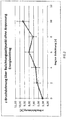
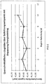
- Fig. 2 and 3 show the corresponding curves for the z-elongation at break and the cross-sectional area, which were determined in an exemplary preliminary test.
- an exposure parameter for example the emitted light power
- a pre-factor function value f (t)
- Fig. 4 shows the time dependency of such a prefactor.
- the emitted light power can either be reduced step by step during the predetermined time period, or a monotonically decreasing function f (t) is fitted to the table values.
- Fig. 5 and 6th show the z-elongation at break and the cross-sectional area of a test run with z-tension rods, in which (with otherwise identical construction parameters) the emitted light output was gradually reduced over a period of 12 seconds from the beginning of the exposure. You can see in comparison with the Fig. 2 and 3 that approximately constant values are obtained for the z-elongation at break and the cross-sectional area independent of the exposure time.
- thermal energy to be introduced per unit area Determine the beginning of the exposure period.
- the thermal energy to be introduced depends on the powder material and is also determined by the type and arrangement of the heating device 9. It is therefore most useful to determine the functional values using the pre-test described.
- the amount of heat to be introduced per unit area at the beginning of the exposure period of a layer can also be determined by preliminary tests, in which the influence of the powder preheating temperature on the mechanical properties and the geometry of the pretest components is not, but the influence of the powder preheating temperature another property of the pre-test components, such as the surface quality, is determined.
- the thermal energy introduced into the building material for consolidation per unit area does not necessarily have to be varied by varying the light power emitted.
- the energy input per unit area can also be varied by varying the speed at which the laser sweeps over the construction field 5. The faster the laser beam moves over the construction field 5, the less heat energy per unit of time is introduced into the construction material.
- the laser beam can therefore be moved over the construction field 5 at a lower speed at the beginning of the predetermined time period than after the predetermined time period has elapsed.
- the thermal energy introduced per unit area is also dependent on the distance between the adjacent tracks of the laser beam sweeping over the construction field. This means that by gradually increasing the distance between adjacent tracks of the laser beam 7, a gradual reduction in the thermal energy introduced into the material per unit area can also be achieved.
- the emitted light power can be varied in pulsed operation by changing the frequency or the duty cycle.
- control device 10 regulates the corresponding parameters as a function of time.
- the above-described adjustment of the introduced thermal energy per unit area is to be used accordingly for the contour exposure or the exposure of the interior of the cross-section, depending on the situation whether the contour or the inside of the cross-section are exposed first.
- the thermal energy introduced per unit area varied, but the "beam offset" is also adjusted during the predetermined period of time.
- the beam offset denotes an amount by which the laser beam is shifted inward on the contour of the object in order to take into account, among other things, that due to the heat conduction, the powder is also solidified immediately outside the area to be solidified, which changes the object dimensions. Accordingly, a lower beam offset is selected at the beginning of the exposure period and this beam offset is gradually increased during the predetermined period.
- the length of the predetermined period of time during which the thermal energy introduced per unit area is gradually reduced or the beam offset is gradually increased can be determined using the pre-tests described. As soon as the mechanical properties that are determined in the preliminary tests and / or the object dimensions in the preliminary tests are within the tolerance range specified for the object to be mass-produced, a variation of the exposure parameters is no longer necessary.
- the pre-tests can therefore be used to determine the point in time from the beginning of the exposure from which the properties are within the tolerance range. This point in time then defines the end of the predetermined period of time.
- the predetermined period of time lies in a range between 1 and 15 seconds. However, longer periods of time are also possible, particularly in the case of large layer thicknesses.
- the present invention is not based on this type of thermal energy input limited.
- the thermal energy required for solidification can be introduced in the same way over a large area, which is why the area of incidence of the radiation used to solidify the material on the powder layer can generally be referred to as the "area of incidence of solidification radiation".
- the invention always leads to an advantageous acceleration of the construction process when not all points of the object cross-section are solidified at the same time, but rather different points of the object cross-section are solidified at different times.
- the present invention is not limited to the use of electromagnetic radiation, but can also be implemented in the same way in connection with particle radiation for introducing the thermal energy into the building material.
- the present invention encompasses both methods in which the building material is completely melted and methods in which sintering takes place in which the powder particles are only melted on the surface.
Landscapes
- Engineering & Computer Science (AREA)
- Chemical & Material Sciences (AREA)
- Materials Engineering (AREA)
- Manufacturing & Machinery (AREA)
- Mechanical Engineering (AREA)
- Physics & Mathematics (AREA)
- Optics & Photonics (AREA)
- Automation & Control Theory (AREA)
- Ceramic Engineering (AREA)
- Plasma & Fusion (AREA)
Claims (7)
- Procédé pour la constitution couche par couche d'un objet tridimensionnel (3) à partir d'un matériau de construction pulvérulent au moyen d'une solidification successive de couches du matériau de construction pulvérulent respectivement aux endroits d'une couche qui correspondent à une section transversale de l'objet, dans lequel la solidification est effectuée par introduction d'énergie thermique et le procédé pour chaque couche présente les étapes suivantes :une étape de fourniture d'une couche d'un matériau de construction pulvérulent sur une base de construction (2) ou une couche déjà solidifiée préalablement en des endroits sélectionnés,une étape de préchauffage du matériau de construction appliqué à une température de préchauffage, au-dessous de la température à laquelle le matériau est solidifié, etune étape de solidification de la couche appliquée au moyen d'un rayonnement électromagnétique ou rayonnement particulaire (7), pour laquelle une zone d'impact de rayonnement de solidification balaye l'un après l'autre tous les endroits de la couche correspondant à la section transversale de l'objet, de sorte que la poudre est solidifiée à ces endroits par l'énergie thermique introduite par le rayonnement,caractérisé en ce quedans l'étape de solidification, qui a commencé avant que la couche de poudre appliquée n'ait atteint une température de travail souhaitée, pendant une période prédéfinie, dont le commencement coïncide avec le début de l'étape de solidification, la quantité de chaleur introduite dans la zone d'impact de rayonnement de solidification par unité de surface est diminuée avec le temps et peut être décrite par une fonction décroissant de façon monotone en fonction du temps,du fait que la quantité de chaleur entrée par unité de surface est diminuée par un abaissement de la densité de puissance dans la zone d'impact de rayonnement de solidification balayant la poudre et/ouque la quantité de chaleur entrée par unité de surface est diminuée par une augmentation de la vitesse à laquelle la zone d'impact de rayonnement de solidification balaye la couche de poudre.
- Procédé selon la revendication 1, selon lequel la solidification est effectuée au moyen d'au moins un faisceau de photons ou de particules, qui est dirigé l'un après l'autre sur les endroits à solidifier de la couche.
- Procédé selon la revendication 1, selon lequel la solidification est effectuée au moyen d'un rayonnement électromagnétique et la zone d'impact de rayonnement de solidification est plate.
- Procédé selon l'une quelconque des revendications 1 à 3, selon lequel la fonction décroissant de façon monotone est déterminée de manière empirique, du fait que la modification de température de la couche de matériau de construction lors d'un chauffage à des températures au-dessous de la température à laquelle la solidification a lieu est déterminée dans des essais préliminaires, pour lesquels- plusieurs objets (3) à fabriquer ou plusieurs éprouvettes sont fabriqué(e)s,- des sections transversales des objets (3) à fabriquer ou éprouvettes sont solidifiées à différents moments au début de l'étape de solidification d'une couche, et- à l'issue du processus de construction, une propriété des objets (3) à fabriquer ou éprouvettes est déterminée, et- la fonction mentionnée après la quantité de chaleur introduite par unité de surface est diminuée pendant la période prédéfinie et la longueur de la période prédéfinie sont déterminées sur la base de la propriété déterminée des objets (3) à fabriquer ou éprouvettes.
- Procédé selon la revendication 4, selon lequel la propriété déterminée sur les objets (3) à fabriquer ou éprouvettes est une propriété mécanique, une dimension ou un paramètre pour décrire la qualité de surface.
- Dispositif pour la constitution couche par couche d'un objet tridimensionnel selon un procédé selon l'une quelconque des revendications 1 à 5, dans lequel le dispositif présente :une base de construction (2) pour porter l'objet (3) à former ;un dispositif d'application (11, 12) pour appliquer une couche du matériau de construction pulvérulent sur la surface du support ou une couche déjà au moins en partie solidifiée,un dispositif de chauffage (9), lequel peut fournir de l'énergie thermique pour le préchauffage surfacique de la couche de matériau de construction pulvérulent,un dispositif d'irradiation (6, 8), qui émet un rayonnement électromagnétique ou rayonnement particulaire (7) et est en mesure de balayer avec une zone d'impact de rayonnement de solidification l'un après l'autre tous les endroits de la couche correspondant à la section transversale de l'objet, de sorte que la poudre est solidifiée à ces endroits par l'énergie thermique introduite par le rayonnement, etun système de commande (10), lequel commande le dispositif de sorte qu'après l'abaissement de la base de construction (2) d'une valeur correspondant à une épaisseur de couche, le dispositif d'application applique une couche du matériau de construction pulvérulent sur la base de construction (2) ou une couche déjà solidifiée préalablement à des endroits sélectionnés et ensuite le dispositif d'irradiation (6, 8) solidifie le matériau de construction pulvérulent dans une zone qui correspond à une section transversale de l'objet, du fait que la zone d'impact de rayonnement de solidification balaye l'un après l'autre tous les endroits de la couche correspondant à la section transversale de l'objet, de sorte que la poudre est solidifiée à ces endroits par l'énergie thermique introduite par le rayonnement,caractérisé en ce que le système de commande (10) commande le dispositif d'irradiation (6, 8), de sorte que pendant une période prédéfinie à partir du début de la solidification de la poudre dans une couche de poudre par le dispositif d'irradiation (6, 8), qui a commencé avant que la couche de poudre appliquée n'ait atteint une température de travail souhaitée, la quantité de chaleur introduite par le dispositif d'irradiation (6, 8) dans la zone d'impact de rayonnement de solidification dans le matériau de construction pulvérulent par unité de surface décroit de manière correspondante à une fonction décroissant de façon monotone en fonction du temps,du fait que la quantité de chaleur entrée par unité de surface est diminuée par un abaissement de la densité de puissance dans la zone d'impact de rayonnement de solidification balayant la poudre et/oula quantité de chaleur entrée par unité de surface est diminuée par une augmentation de la vitesse à laquelle la zone d'impact de rayonnement de solidification balaye la couche de poudre.
- Dispositif selon la revendication 6 avec un dispositif de mesure de température (14), qui est adapté à mesurer sans contact la température d'une zone partielle d'une couche de poudre.
Applications Claiming Priority (2)
| Application Number | Priority Date | Filing Date | Title |
|---|---|---|---|
| DE102013224693.5A DE102013224693A1 (de) | 2013-12-02 | 2013-12-02 | Verfahren zur beschleunigten Herstellung von Objekten mittels generativer Fertigung |
| PCT/EP2014/076150 WO2015082423A1 (fr) | 2013-12-02 | 2014-12-01 | Procédé de production accélérée d'objets par fabrication générative |
Publications (2)
| Publication Number | Publication Date |
|---|---|
| EP3077180A1 EP3077180A1 (fr) | 2016-10-12 |
| EP3077180B1 true EP3077180B1 (fr) | 2021-08-04 |
Family
ID=52023469
Family Applications (1)
| Application Number | Title | Priority Date | Filing Date |
|---|---|---|---|
| EP14811793.0A Active EP3077180B1 (fr) | 2013-12-02 | 2014-12-01 | Procédé de production accélérée d'objets par fabrication générative |
Country Status (5)
| Country | Link |
|---|---|
| US (1) | US10981322B2 (fr) |
| EP (1) | EP3077180B1 (fr) |
| CN (1) | CN105829073A (fr) |
| DE (1) | DE102013224693A1 (fr) |
| WO (1) | WO2015082423A1 (fr) |
Families Citing this family (12)
| Publication number | Priority date | Publication date | Assignee | Title |
|---|---|---|---|---|
| DE102015225022A1 (de) * | 2015-12-11 | 2017-06-14 | Eos Gmbh Electro Optical Systems | Verfahren und Vorrichtung zur Prüfung eines Eingangsdatensatzes einer generativen Schichtbauvorrichtung |
| DE102015225012A1 (de) * | 2015-12-11 | 2017-06-14 | Eos Gmbh Electro Optical Systems | Verfahren und Vorrichtung zur Prüfung eines Eingangsdatensatzes einer generativen Schichtbauvorrichtung |
| WO2017098003A2 (fr) | 2015-12-11 | 2017-06-15 | Eos Gmbh Electro Optical Systems | Procédé et dispositif destinés à tester un ensemble de données d'entrée d'un dispositif de construction par couches génératif |
| DE102017212110A1 (de) * | 2017-07-14 | 2019-01-17 | Siemens Aktiengesellschaft | Verfahren für ein additiv herzustellendes Bauteil mit vorbestimmter Oberflächenstruktur |
| WO2019032224A1 (fr) * | 2017-08-07 | 2019-02-14 | University Of South Florida | Plateforme d'essai de frittage de grande surface et procédé d'utilisation associé |
| CN111526954B (zh) * | 2017-11-10 | 2022-12-23 | 通用电气公司 | 交错扫描的策略及其应用 |
| EP3498401A1 (fr) * | 2017-12-18 | 2019-06-19 | Siemens Aktiengesellschaft | Procédé de fabrication additive d'un composant, appareil et produit-programme d'ordinateur |
| US10695867B2 (en) | 2018-03-08 | 2020-06-30 | General Electric Company | Controlling microstructure of selected range of layers of object during additive manufacture |
| DE102018205688A1 (de) * | 2018-04-13 | 2019-10-17 | Eos Gmbh Electro Optical Systems | Verfahren und Vorrichtung zur Verbesserung der Bauteilqualität von durch ein additives Herstellverfahren hergestellten Objekten |
| WO2020065657A2 (fr) | 2018-09-27 | 2020-04-02 | Stratasys Ltd. | Procédé et système de fabrication additive à l'aide d'une commande de température en boucle fermée |
| FR3092020B1 (fr) * | 2019-01-28 | 2021-01-08 | Addup | Fabrication additive par modulation de puissance laser |
| DE112019007356B4 (de) | 2019-06-25 | 2024-10-17 | Mitsubishi Electric Corporation | Numerische Steuerung und Verfahren zum Steuern einer additiven Herstellungsvorrichtung |
Family Cites Families (13)
| Publication number | Priority date | Publication date | Assignee | Title |
|---|---|---|---|---|
| US5427733A (en) * | 1993-10-20 | 1995-06-27 | United Technologies Corporation | Method for performing temperature-controlled laser sintering |
| DE19516972C1 (de) | 1995-05-09 | 1996-12-12 | Eos Electro Optical Syst | Vorrichtung zum Herstellen eines dreidimensionalen Objektes mittels Lasersintern |
| US6451631B1 (en) * | 2000-08-10 | 2002-09-17 | Hitachi America, Ltd. | Thin film crystal growth by laser annealing |
| US20040254665A1 (en) | 2003-06-10 | 2004-12-16 | Fink Jeffrey E. | Optimal dimensional and mechanical properties of laser sintered hardware by thermal analysis and parameter optimization |
| US7569174B2 (en) * | 2004-12-07 | 2009-08-04 | 3D Systems, Inc. | Controlled densification of fusible powders in laser sintering |
| DE102005015870B3 (de) * | 2005-04-06 | 2006-10-26 | Eos Gmbh Electro Optical Systems | Vorrichtung und Verfahren zum Herstellen eines dreidimensionalen Objekts |
| DE102005030854B3 (de) | 2005-07-01 | 2007-03-08 | Eos Gmbh Electro Optical Systems | Vorrichtung zum Herstellen eines dreidimensionalen Objektes |
| US20070212859A1 (en) * | 2006-03-08 | 2007-09-13 | Paul Carey | Method of thermal processing structures formed on a substrate |
| EP2292357B1 (fr) | 2009-08-10 | 2016-04-06 | BEGO Bremer Goldschlägerei Wilh.-Herbst GmbH & Co KG | Article céramique et procédés de production de cet article |
| DE202009012628U1 (de) | 2009-09-17 | 2009-12-10 | Eos Gmbh Electro Optical Systems | Vorrichtung zum generativen Herstellen eines dreidimensionalen Objektes |
| DE102010019447A1 (de) * | 2010-05-05 | 2011-11-10 | Eos Gmbh Electro Optical Systems | Verfahren zum generativen Herstellen eines dreidimensionalen Objekts mit Räumelementen und Verfahren zum Erstellen eines entsprechenden Datensatzes |
| US9073265B2 (en) * | 2011-01-28 | 2015-07-07 | Arcam Ab | Method for production of a three-dimensional body |
| WO2014144482A1 (fr) * | 2013-03-15 | 2014-09-18 | Matterfab Corp. | Appareil et procédés de fabrication |
-
2013
- 2013-12-02 DE DE102013224693.5A patent/DE102013224693A1/de not_active Ceased
-
2014
- 2014-12-01 US US15/037,109 patent/US10981322B2/en active Active
- 2014-12-01 EP EP14811793.0A patent/EP3077180B1/fr active Active
- 2014-12-01 CN CN201480065654.0A patent/CN105829073A/zh active Pending
- 2014-12-01 WO PCT/EP2014/076150 patent/WO2015082423A1/fr not_active Ceased
Non-Patent Citations (1)
| Title |
|---|
| None * |
Also Published As
| Publication number | Publication date |
|---|---|
| CN105829073A (zh) | 2016-08-03 |
| EP3077180A1 (fr) | 2016-10-12 |
| WO2015082423A1 (fr) | 2015-06-11 |
| DE102013224693A1 (de) | 2015-06-03 |
| US10981322B2 (en) | 2021-04-20 |
| US20160279872A1 (en) | 2016-09-29 |
Similar Documents
| Publication | Publication Date | Title |
|---|---|---|
| EP3077180B1 (fr) | Procédé de production accélérée d'objets par fabrication générative | |
| EP3059076B1 (fr) | Procede et dispositif destines a fabriquer un objet tridimensionnel | |
| EP3099469B1 (fr) | Procédé et dispositif de commande améliorée de l'apport d'énergie dans un procédé de construction additive par génération de couches | |
| EP0759848B1 (fr) | Procede et dispositif permettant de produire un objet en trois dimensions par frittage au laser | |
| DE102012012344B4 (de) | Verfahren und Vorrichtung zur Herstellung von Werkstücken durch Strahlschmelzen pulverförmigen Materials | |
| EP3285988B1 (fr) | Procédé et dispositif de fabrication d'un objet tridimensionnel | |
| EP2340925B1 (fr) | Procédé de fabrication générative d'un objet tridimensionnel doté d'une amenée de chaleur en continu | |
| EP2864108B1 (fr) | Dispositif et procédé de fabrication par couches d'un objet tridimensionnel | |
| EP3225334B1 (fr) | Procédé et dispositif de fabrication additive d'au moins une partie d'un composant | |
| EP3022008B1 (fr) | Procédé de fabrication d'une composant et dispositif de rayonnement optique | |
| EP3718729B1 (fr) | Procédé de fabrication à fabrication additive de composants et traitement ultérieur | |
| EP3318352A1 (fr) | Procédé de détection basé sur la simulation de zones de composants thermiquement critiques et procédé d'adaptation spécifique aux composants d'une génération de chaleur locale lors de la fabrication additive | |
| DE102016203955B4 (de) | Verfahren zur Bereitstellung eines Steuerbefehlssatzes, generative Schichtbauvorrichtung, Steuereinrichtung und Computerprogramm | |
| WO2014202415A2 (fr) | Dispositif et procédé de fabrication additive d'au moins une partie d'une pièce | |
| WO2018197443A1 (fr) | Homogénéisation de l'apport énergétique | |
| DE102018202506A1 (de) | Additives Herstellverfahren mit kontrollierter Verfestigung und zugehörige Vorrichtung | |
| EP3342583A1 (fr) | Procédé et dispositif de fabrication additive d'un objet tridimensionnel | |
| EP3349928A1 (fr) | Procédé de fabrication additive, pièce et dispositif de fabrication additive | |
| EP0737130B1 (fr) | Procede et dispositif pour la production d'un objet a trois dimensions | |
| EP4519038A1 (fr) | Procédé et dispositif de génération de données de commande d'irradiation pour un dispositif de fabrication additive d'un composant | |
| WO2026037631A1 (fr) | Procédé de paramétrage optimisé dans la fabrication additive de composants tridimensionnels |
Legal Events
| Date | Code | Title | Description |
|---|---|---|---|
| PUAI | Public reference made under article 153(3) epc to a published international application that has entered the european phase |
Free format text: ORIGINAL CODE: 0009012 |
|
| 17P | Request for examination filed |
Effective date: 20160701 |
|
| AK | Designated contracting states |
Kind code of ref document: A1 Designated state(s): AL AT BE BG CH CY CZ DE DK EE ES FI FR GB GR HR HU IE IS IT LI LT LU LV MC MK MT NL NO PL PT RO RS SE SI SK SM TR |
|
| AX | Request for extension of the european patent |
Extension state: BA ME |
|
| DAX | Request for extension of the european patent (deleted) | ||
| STAA | Information on the status of an ep patent application or granted ep patent |
Free format text: STATUS: EXAMINATION IS IN PROGRESS |
|
| 17Q | First examination report despatched |
Effective date: 20181129 |
|
| REG | Reference to a national code |
Ref country code: DE Ref legal event code: R079 Ref document number: 502014015789 Country of ref document: DE Free format text: PREVIOUS MAIN CLASS: B29C0067000000 Ipc: B29C0064153000 |
|
| GRAP | Despatch of communication of intention to grant a patent |
Free format text: ORIGINAL CODE: EPIDOSNIGR1 |
|
| STAA | Information on the status of an ep patent application or granted ep patent |
Free format text: STATUS: GRANT OF PATENT IS INTENDED |
|
| RIC1 | Information provided on ipc code assigned before grant |
Ipc: B33Y 50/02 20150101ALI20201007BHEP Ipc: B33Y 30/00 20150101ALI20201007BHEP Ipc: B29C 64/153 20170101AFI20201007BHEP Ipc: B29C 64/40 20170101ALI20201007BHEP Ipc: B29C 64/393 20170101ALI20201007BHEP Ipc: B33Y 10/00 20150101ALI20201007BHEP |
|
| INTG | Intention to grant announced |
Effective date: 20201030 |
|
| GRAJ | Information related to disapproval of communication of intention to grant by the applicant or resumption of examination proceedings by the epo deleted |
Free format text: ORIGINAL CODE: EPIDOSDIGR1 |
|
| STAA | Information on the status of an ep patent application or granted ep patent |
Free format text: STATUS: EXAMINATION IS IN PROGRESS |
|
| GRAP | Despatch of communication of intention to grant a patent |
Free format text: ORIGINAL CODE: EPIDOSNIGR1 |
|
| STAA | Information on the status of an ep patent application or granted ep patent |
Free format text: STATUS: GRANT OF PATENT IS INTENDED |
|
| INTC | Intention to grant announced (deleted) | ||
| INTG | Intention to grant announced |
Effective date: 20210325 |
|
| GRAS | Grant fee paid |
Free format text: ORIGINAL CODE: EPIDOSNIGR3 |
|
| GRAA | (expected) grant |
Free format text: ORIGINAL CODE: 0009210 |
|
| STAA | Information on the status of an ep patent application or granted ep patent |
Free format text: STATUS: THE PATENT HAS BEEN GRANTED |
|
| AK | Designated contracting states |
Kind code of ref document: B1 Designated state(s): AL AT BE BG CH CY CZ DE DK EE ES FI FR GB GR HR HU IE IS IT LI LT LU LV MC MK MT NL NO PL PT RO RS SE SI SK SM TR |
|
| REG | Reference to a national code |
Ref country code: GB Ref legal event code: FG4D Free format text: NOT ENGLISH |
|
| REG | Reference to a national code |
Ref country code: AT Ref legal event code: REF Ref document number: 1416542 Country of ref document: AT Kind code of ref document: T Effective date: 20210815 |
|
| REG | Reference to a national code |
Ref country code: CH Ref legal event code: EP |
|
| REG | Reference to a national code |
Ref country code: DE Ref legal event code: R096 Ref document number: 502014015789 Country of ref document: DE |
|
| REG | Reference to a national code |
Ref country code: IE Ref legal event code: FG4D Free format text: LANGUAGE OF EP DOCUMENT: GERMAN |
|
| REG | Reference to a national code |
Ref country code: NL Ref legal event code: FP |
|
| REG | Reference to a national code |
Ref country code: LT Ref legal event code: MG9D |
|
| PG25 | Lapsed in a contracting state [announced via postgrant information from national office to epo] |
Ref country code: RS Free format text: LAPSE BECAUSE OF FAILURE TO SUBMIT A TRANSLATION OF THE DESCRIPTION OR TO PAY THE FEE WITHIN THE PRESCRIBED TIME-LIMIT Effective date: 20210804 Ref country code: SE Free format text: LAPSE BECAUSE OF FAILURE TO SUBMIT A TRANSLATION OF THE DESCRIPTION OR TO PAY THE FEE WITHIN THE PRESCRIBED TIME-LIMIT Effective date: 20210804 Ref country code: HR Free format text: LAPSE BECAUSE OF FAILURE TO SUBMIT A TRANSLATION OF THE DESCRIPTION OR TO PAY THE FEE WITHIN THE PRESCRIBED TIME-LIMIT Effective date: 20210804 Ref country code: LT Free format text: LAPSE BECAUSE OF FAILURE TO SUBMIT A TRANSLATION OF THE DESCRIPTION OR TO PAY THE FEE WITHIN THE PRESCRIBED TIME-LIMIT Effective date: 20210804 Ref country code: BG Free format text: LAPSE BECAUSE OF FAILURE TO SUBMIT A TRANSLATION OF THE DESCRIPTION OR TO PAY THE FEE WITHIN THE PRESCRIBED TIME-LIMIT Effective date: 20211104 Ref country code: ES Free format text: LAPSE BECAUSE OF FAILURE TO SUBMIT A TRANSLATION OF THE DESCRIPTION OR TO PAY THE FEE WITHIN THE PRESCRIBED TIME-LIMIT Effective date: 20210804 Ref country code: FI Free format text: LAPSE BECAUSE OF FAILURE TO SUBMIT A TRANSLATION OF THE DESCRIPTION OR TO PAY THE FEE WITHIN THE PRESCRIBED TIME-LIMIT Effective date: 20210804 Ref country code: NO Free format text: LAPSE BECAUSE OF FAILURE TO SUBMIT A TRANSLATION OF THE DESCRIPTION OR TO PAY THE FEE WITHIN THE PRESCRIBED TIME-LIMIT Effective date: 20211104 Ref country code: PT Free format text: LAPSE BECAUSE OF FAILURE TO SUBMIT A TRANSLATION OF THE DESCRIPTION OR TO PAY THE FEE WITHIN THE PRESCRIBED TIME-LIMIT Effective date: 20211206 |
|
| PG25 | Lapsed in a contracting state [announced via postgrant information from national office to epo] |
Ref country code: PL Free format text: LAPSE BECAUSE OF FAILURE TO SUBMIT A TRANSLATION OF THE DESCRIPTION OR TO PAY THE FEE WITHIN THE PRESCRIBED TIME-LIMIT Effective date: 20210804 Ref country code: LV Free format text: LAPSE BECAUSE OF FAILURE TO SUBMIT A TRANSLATION OF THE DESCRIPTION OR TO PAY THE FEE WITHIN THE PRESCRIBED TIME-LIMIT Effective date: 20210804 Ref country code: GR Free format text: LAPSE BECAUSE OF FAILURE TO SUBMIT A TRANSLATION OF THE DESCRIPTION OR TO PAY THE FEE WITHIN THE PRESCRIBED TIME-LIMIT Effective date: 20211105 |
|
| PG25 | Lapsed in a contracting state [announced via postgrant information from national office to epo] |
Ref country code: DK Free format text: LAPSE BECAUSE OF FAILURE TO SUBMIT A TRANSLATION OF THE DESCRIPTION OR TO PAY THE FEE WITHIN THE PRESCRIBED TIME-LIMIT Effective date: 20210804 |
|
| REG | Reference to a national code |
Ref country code: DE Ref legal event code: R097 Ref document number: 502014015789 Country of ref document: DE |
|
| PG25 | Lapsed in a contracting state [announced via postgrant information from national office to epo] |
Ref country code: SM Free format text: LAPSE BECAUSE OF FAILURE TO SUBMIT A TRANSLATION OF THE DESCRIPTION OR TO PAY THE FEE WITHIN THE PRESCRIBED TIME-LIMIT Effective date: 20210804 Ref country code: SK Free format text: LAPSE BECAUSE OF FAILURE TO SUBMIT A TRANSLATION OF THE DESCRIPTION OR TO PAY THE FEE WITHIN THE PRESCRIBED TIME-LIMIT Effective date: 20210804 Ref country code: RO Free format text: LAPSE BECAUSE OF FAILURE TO SUBMIT A TRANSLATION OF THE DESCRIPTION OR TO PAY THE FEE WITHIN THE PRESCRIBED TIME-LIMIT Effective date: 20210804 Ref country code: EE Free format text: LAPSE BECAUSE OF FAILURE TO SUBMIT A TRANSLATION OF THE DESCRIPTION OR TO PAY THE FEE WITHIN THE PRESCRIBED TIME-LIMIT Effective date: 20210804 Ref country code: CZ Free format text: LAPSE BECAUSE OF FAILURE TO SUBMIT A TRANSLATION OF THE DESCRIPTION OR TO PAY THE FEE WITHIN THE PRESCRIBED TIME-LIMIT Effective date: 20210804 Ref country code: AL Free format text: LAPSE BECAUSE OF FAILURE TO SUBMIT A TRANSLATION OF THE DESCRIPTION OR TO PAY THE FEE WITHIN THE PRESCRIBED TIME-LIMIT Effective date: 20210804 |
|
| PLBE | No opposition filed within time limit |
Free format text: ORIGINAL CODE: 0009261 |
|
| STAA | Information on the status of an ep patent application or granted ep patent |
Free format text: STATUS: NO OPPOSITION FILED WITHIN TIME LIMIT |
|
| 26N | No opposition filed |
Effective date: 20220506 |
|
| PG25 | Lapsed in a contracting state [announced via postgrant information from national office to epo] |
Ref country code: MC Free format text: LAPSE BECAUSE OF FAILURE TO SUBMIT A TRANSLATION OF THE DESCRIPTION OR TO PAY THE FEE WITHIN THE PRESCRIBED TIME-LIMIT Effective date: 20210804 |
|
| REG | Reference to a national code |
Ref country code: CH Ref legal event code: PL |
|
| PG25 | Lapsed in a contracting state [announced via postgrant information from national office to epo] |
Ref country code: SI Free format text: LAPSE BECAUSE OF FAILURE TO SUBMIT A TRANSLATION OF THE DESCRIPTION OR TO PAY THE FEE WITHIN THE PRESCRIBED TIME-LIMIT Effective date: 20210804 |
|
| REG | Reference to a national code |
Ref country code: BE Ref legal event code: MM Effective date: 20211231 |
|
| PG25 | Lapsed in a contracting state [announced via postgrant information from national office to epo] |
Ref country code: LU Free format text: LAPSE BECAUSE OF NON-PAYMENT OF DUE FEES Effective date: 20211201 Ref country code: IE Free format text: LAPSE BECAUSE OF NON-PAYMENT OF DUE FEES Effective date: 20211201 |
|
| PG25 | Lapsed in a contracting state [announced via postgrant information from national office to epo] |
Ref country code: BE Free format text: LAPSE BECAUSE OF NON-PAYMENT OF DUE FEES Effective date: 20211231 |
|
| PG25 | Lapsed in a contracting state [announced via postgrant information from national office to epo] |
Ref country code: LI Free format text: LAPSE BECAUSE OF NON-PAYMENT OF DUE FEES Effective date: 20211231 Ref country code: CH Free format text: LAPSE BECAUSE OF NON-PAYMENT OF DUE FEES Effective date: 20211231 |
|
| REG | Reference to a national code |
Ref country code: AT Ref legal event code: MM01 Ref document number: 1416542 Country of ref document: AT Kind code of ref document: T Effective date: 20211201 |
|
| PG25 | Lapsed in a contracting state [announced via postgrant information from national office to epo] |
Ref country code: AT Free format text: LAPSE BECAUSE OF NON-PAYMENT OF DUE FEES Effective date: 20211201 |
|
| PG25 | Lapsed in a contracting state [announced via postgrant information from national office to epo] |
Ref country code: HU Free format text: LAPSE BECAUSE OF FAILURE TO SUBMIT A TRANSLATION OF THE DESCRIPTION OR TO PAY THE FEE WITHIN THE PRESCRIBED TIME-LIMIT; INVALID AB INITIO Effective date: 20141201 |
|
| PG25 | Lapsed in a contracting state [announced via postgrant information from national office to epo] |
Ref country code: CY Free format text: LAPSE BECAUSE OF FAILURE TO SUBMIT A TRANSLATION OF THE DESCRIPTION OR TO PAY THE FEE WITHIN THE PRESCRIBED TIME-LIMIT Effective date: 20210804 |
|
| P01 | Opt-out of the competence of the unified patent court (upc) registered |
Effective date: 20230525 |
|
| PG25 | Lapsed in a contracting state [announced via postgrant information from national office to epo] |
Ref country code: MK Free format text: LAPSE BECAUSE OF FAILURE TO SUBMIT A TRANSLATION OF THE DESCRIPTION OR TO PAY THE FEE WITHIN THE PRESCRIBED TIME-LIMIT Effective date: 20210804 |
|
| PG25 | Lapsed in a contracting state [announced via postgrant information from national office to epo] |
Ref country code: TR Free format text: LAPSE BECAUSE OF FAILURE TO SUBMIT A TRANSLATION OF THE DESCRIPTION OR TO PAY THE FEE WITHIN THE PRESCRIBED TIME-LIMIT Effective date: 20210804 |
|
| PG25 | Lapsed in a contracting state [announced via postgrant information from national office to epo] |
Ref country code: MT Free format text: LAPSE BECAUSE OF FAILURE TO SUBMIT A TRANSLATION OF THE DESCRIPTION OR TO PAY THE FEE WITHIN THE PRESCRIBED TIME-LIMIT Effective date: 20210804 |
|
| PGFP | Annual fee paid to national office [announced via postgrant information from national office to epo] |
Ref country code: DE Payment date: 20251211 Year of fee payment: 12 |
|
| PGFP | Annual fee paid to national office [announced via postgrant information from national office to epo] |
Ref country code: GB Payment date: 20251219 Year of fee payment: 12 |
|
| PGFP | Annual fee paid to national office [announced via postgrant information from national office to epo] |
Ref country code: IT Payment date: 20251223 Year of fee payment: 12 |
|
| PGFP | Annual fee paid to national office [announced via postgrant information from national office to epo] |
Ref country code: FR Payment date: 20251223 Year of fee payment: 12 Ref country code: NL Payment date: 20251219 Year of fee payment: 12 |