EP3077202B1 - Tragendes, flächiges formteil aus einem mehrschichtfaserverbundwerkstoff, insbesondere für eine fahrzeugkarosserie - Google Patents
Tragendes, flächiges formteil aus einem mehrschichtfaserverbundwerkstoff, insbesondere für eine fahrzeugkarosserie Download PDFInfo
- Publication number
- EP3077202B1 EP3077202B1 EP14805897.7A EP14805897A EP3077202B1 EP 3077202 B1 EP3077202 B1 EP 3077202B1 EP 14805897 A EP14805897 A EP 14805897A EP 3077202 B1 EP3077202 B1 EP 3077202B1
- Authority
- EP
- European Patent Office
- Prior art keywords
- layer
- shaped part
- fibres
- supporting
- part according
- Prior art date
- Legal status (The legal status is an assumption and is not a legal conclusion. Google has not performed a legal analysis and makes no representation as to the accuracy of the status listed.)
- Not-in-force
Links
- 239000002131 composite material Substances 0.000 title claims description 8
- 239000002657 fibrous material Substances 0.000 title description 3
- 239000000835 fiber Substances 0.000 claims description 69
- 239000011159 matrix material Substances 0.000 claims description 47
- 238000000926 separation method Methods 0.000 claims description 14
- 238000005452 bending Methods 0.000 claims description 13
- 239000000463 material Substances 0.000 claims description 8
- 229920000728 polyester Polymers 0.000 claims description 7
- 150000002118 epoxides Chemical class 0.000 claims description 3
- 239000011185 multilayer composite material Substances 0.000 claims description 3
- 229920001169 thermoplastic Polymers 0.000 claims description 3
- 229920001187 thermosetting polymer Polymers 0.000 claims description 3
- 239000004416 thermosoftening plastic Substances 0.000 claims description 3
- 239000004698 Polyethylene Substances 0.000 claims description 2
- 239000003365 glass fiber Substances 0.000 claims description 2
- -1 polyethylene Polymers 0.000 claims description 2
- 229920000573 polyethylene Polymers 0.000 claims description 2
- 229920002635 polyurethane Polymers 0.000 claims description 2
- 239000004814 polyurethane Substances 0.000 claims description 2
- OKTJSMMVPCPJKN-UHFFFAOYSA-N Carbon Chemical compound [C] OKTJSMMVPCPJKN-UHFFFAOYSA-N 0.000 claims 1
- 229920003235 aromatic polyamide Polymers 0.000 claims 1
- 229910052799 carbon Inorganic materials 0.000 claims 1
- 238000000465 moulding Methods 0.000 description 18
- 229920000049 Carbon (fiber) Polymers 0.000 description 4
- 229920002430 Fibre-reinforced plastic Polymers 0.000 description 4
- 239000004917 carbon fiber Substances 0.000 description 4
- 238000011161 development Methods 0.000 description 4
- 230000018109 developmental process Effects 0.000 description 4
- 239000011151 fibre-reinforced plastic Substances 0.000 description 4
- 239000004033 plastic Substances 0.000 description 4
- 229920003023 plastic Polymers 0.000 description 4
- 239000004593 Epoxy Substances 0.000 description 3
- 239000012528 membrane Substances 0.000 description 3
- 229910000831 Steel Inorganic materials 0.000 description 1
- 238000010521 absorption reaction Methods 0.000 description 1
- XAGFODPZIPBFFR-UHFFFAOYSA-N aluminium Chemical compound [Al] XAGFODPZIPBFFR-UHFFFAOYSA-N 0.000 description 1
- 229910052782 aluminium Inorganic materials 0.000 description 1
- 239000004760 aramid Substances 0.000 description 1
- 229920006231 aramid fiber Polymers 0.000 description 1
- 239000004918 carbon fiber reinforced polymer Substances 0.000 description 1
- 239000011248 coating agent Substances 0.000 description 1
- 238000000576 coating method Methods 0.000 description 1
- 150000001875 compounds Chemical class 0.000 description 1
- 230000032798 delamination Effects 0.000 description 1
- 230000001419 dependent effect Effects 0.000 description 1
- 230000005489 elastic deformation Effects 0.000 description 1
- 238000009434 installation Methods 0.000 description 1
- 239000010959 steel Substances 0.000 description 1
- 238000004381 surface treatment Methods 0.000 description 1
- 238000009864 tensile test Methods 0.000 description 1
Images
Classifications
-
- B—PERFORMING OPERATIONS; TRANSPORTING
- B32—LAYERED PRODUCTS
- B32B—LAYERED PRODUCTS, i.e. PRODUCTS BUILT-UP OF STRATA OF FLAT OR NON-FLAT, e.g. CELLULAR OR HONEYCOMB, FORM
- B32B27/00—Layered products comprising a layer of synthetic resin
- B32B27/06—Layered products comprising a layer of synthetic resin as the main or only constituent of a layer, which is next to another layer of the same or of a different material
- B32B27/08—Layered products comprising a layer of synthetic resin as the main or only constituent of a layer, which is next to another layer of the same or of a different material of synthetic resin
-
- B—PERFORMING OPERATIONS; TRANSPORTING
- B32—LAYERED PRODUCTS
- B32B—LAYERED PRODUCTS, i.e. PRODUCTS BUILT-UP OF STRATA OF FLAT OR NON-FLAT, e.g. CELLULAR OR HONEYCOMB, FORM
- B32B27/00—Layered products comprising a layer of synthetic resin
- B32B27/36—Layered products comprising a layer of synthetic resin comprising polyesters
-
- B—PERFORMING OPERATIONS; TRANSPORTING
- B32—LAYERED PRODUCTS
- B32B—LAYERED PRODUCTS, i.e. PRODUCTS BUILT-UP OF STRATA OF FLAT OR NON-FLAT, e.g. CELLULAR OR HONEYCOMB, FORM
- B32B27/00—Layered products comprising a layer of synthetic resin
- B32B27/38—Layered products comprising a layer of synthetic resin comprising epoxy resins
-
- B—PERFORMING OPERATIONS; TRANSPORTING
- B60—VEHICLES IN GENERAL
- B60R—VEHICLES, VEHICLE FITTINGS, OR VEHICLE PARTS, NOT OTHERWISE PROVIDED FOR
- B60R19/00—Wheel guards; Radiator guards, e.g. grilles; Obstruction removers; Fittings damping bouncing force in collisions
- B60R19/02—Bumpers, i.e. impact receiving or absorbing members for protecting vehicles or fending off blows from other vehicles or objects
- B60R19/03—Bumpers, i.e. impact receiving or absorbing members for protecting vehicles or fending off blows from other vehicles or objects characterised by material, e.g. composite
-
- B—PERFORMING OPERATIONS; TRANSPORTING
- B62—LAND VEHICLES FOR TRAVELLING OTHERWISE THAN ON RAILS
- B62D—MOTOR VEHICLES; TRAILERS
- B62D25/00—Superstructure or monocoque structure sub-units; Parts or details thereof not otherwise provided for
- B62D25/08—Front or rear portions
- B62D25/082—Engine compartments
-
- B—PERFORMING OPERATIONS; TRANSPORTING
- B62—LAND VEHICLES FOR TRAVELLING OTHERWISE THAN ON RAILS
- B62D—MOTOR VEHICLES; TRAILERS
- B62D25/00—Superstructure or monocoque structure sub-units; Parts or details thereof not otherwise provided for
- B62D25/08—Front or rear portions
- B62D25/14—Dashboards as superstructure sub-units
-
- B—PERFORMING OPERATIONS; TRANSPORTING
- B62—LAND VEHICLES FOR TRAVELLING OTHERWISE THAN ON RAILS
- B62D—MOTOR VEHICLES; TRAILERS
- B62D29/00—Superstructures, understructures, or sub-units thereof, characterised by the material thereof
- B62D29/04—Superstructures, understructures, or sub-units thereof, characterised by the material thereof predominantly of synthetic material
- B62D29/043—Superstructures
-
- B—PERFORMING OPERATIONS; TRANSPORTING
- B32—LAYERED PRODUCTS
- B32B—LAYERED PRODUCTS, i.e. PRODUCTS BUILT-UP OF STRATA OF FLAT OR NON-FLAT, e.g. CELLULAR OR HONEYCOMB, FORM
- B32B2250/00—Layers arrangement
- B32B2250/40—Symmetrical or sandwich layers, e.g. ABA, ABCBA, ABCCBA
-
- B—PERFORMING OPERATIONS; TRANSPORTING
- B32—LAYERED PRODUCTS
- B32B—LAYERED PRODUCTS, i.e. PRODUCTS BUILT-UP OF STRATA OF FLAT OR NON-FLAT, e.g. CELLULAR OR HONEYCOMB, FORM
- B32B2262/00—Composition or structural features of fibres which form a fibrous or filamentary layer or are present as additives
- B32B2262/02—Synthetic macromolecular fibres
- B32B2262/0261—Polyamide fibres
- B32B2262/0269—Aromatic polyamide fibres
-
- B—PERFORMING OPERATIONS; TRANSPORTING
- B32—LAYERED PRODUCTS
- B32B—LAYERED PRODUCTS, i.e. PRODUCTS BUILT-UP OF STRATA OF FLAT OR NON-FLAT, e.g. CELLULAR OR HONEYCOMB, FORM
- B32B2262/00—Composition or structural features of fibres which form a fibrous or filamentary layer or are present as additives
- B32B2262/10—Inorganic fibres
- B32B2262/101—Glass fibres
-
- B—PERFORMING OPERATIONS; TRANSPORTING
- B32—LAYERED PRODUCTS
- B32B—LAYERED PRODUCTS, i.e. PRODUCTS BUILT-UP OF STRATA OF FLAT OR NON-FLAT, e.g. CELLULAR OR HONEYCOMB, FORM
- B32B2262/00—Composition or structural features of fibres which form a fibrous or filamentary layer or are present as additives
- B32B2262/10—Inorganic fibres
- B32B2262/106—Carbon fibres, e.g. graphite fibres
-
- B—PERFORMING OPERATIONS; TRANSPORTING
- B32—LAYERED PRODUCTS
- B32B—LAYERED PRODUCTS, i.e. PRODUCTS BUILT-UP OF STRATA OF FLAT OR NON-FLAT, e.g. CELLULAR OR HONEYCOMB, FORM
- B32B2307/00—Properties of the layers or laminate
- B32B2307/50—Properties of the layers or laminate having particular mechanical properties
- B32B2307/546—Flexural strength; Flexion stiffness
-
- B—PERFORMING OPERATIONS; TRANSPORTING
- B32—LAYERED PRODUCTS
- B32B—LAYERED PRODUCTS, i.e. PRODUCTS BUILT-UP OF STRATA OF FLAT OR NON-FLAT, e.g. CELLULAR OR HONEYCOMB, FORM
- B32B2307/00—Properties of the layers or laminate
- B32B2307/70—Other properties
- B32B2307/748—Releasability
-
- B—PERFORMING OPERATIONS; TRANSPORTING
- B32—LAYERED PRODUCTS
- B32B—LAYERED PRODUCTS, i.e. PRODUCTS BUILT-UP OF STRATA OF FLAT OR NON-FLAT, e.g. CELLULAR OR HONEYCOMB, FORM
- B32B2605/00—Vehicles
-
- B—PERFORMING OPERATIONS; TRANSPORTING
- B32—LAYERED PRODUCTS
- B32B—LAYERED PRODUCTS, i.e. PRODUCTS BUILT-UP OF STRATA OF FLAT OR NON-FLAT, e.g. CELLULAR OR HONEYCOMB, FORM
- B32B2605/00—Vehicles
- B32B2605/10—Trains
Definitions
- the present invention relates to a load-bearing, flat molded part made of a multilayer fiber composite material, in particular for a vehicle body, and a vehicle body with such a molded part.
- the publication DE 102012203727 A1 shows, for example, a wall element which is made of a fiber-reinforced plastic.
- a wall element which is made of a fiber-reinforced plastic.
- Such a wall element may be used as an end wall in a motor vehicle body, wherein the end wall between A-pillars extends transversely to a vehicle main driving direction and a front end portion of a rear area and an engine compartment separates from a passenger compartment.
- Such an end wall made of fiber-reinforced plastic has the advantage that it is lightweight, has a relatively high strength and stiffens the body sufficiently well.
- Fiber-reinforced plastics in particular carbon fiber reinforced plastics, however, have the property that they have a relatively low deformability, and fail brittle after a small deformation path.
- the publication DE 39 34 555 A1 describes a fiber-reinforced sandwich laminate for structural components, in particular body parts of motor vehicles. It is the object of the present invention to provide a load-bearing, flat molded part consisting of a multilayer fiber composite material, which has an increased deformability, in particular in the case of a bending load.
- a load-bearing, flat shaped part consists of a multilayer fiber composite material.
- the molding is suitable for a vehicle body as part of a crash structure of the vehicle.
- the molded part has at least a first support layer and a second support layer, between which a connecting layer is arranged, which is designed such that a layer separation between the first support layer and the second support layer occurs during a bending stress of the molded part.
- the connecting layer and the supporting layer have a common matrix system.
- the multi-layeredness thus relates to the multiple fiber layers which are embedded in a common matrix system or a common matrix.
- the matrix is a material, in particular a plastic, in which the fibers are embedded.
- the said layer separation is preferably carried out at a previously set threshold load or threshold load.
- the delamination leads to a reduction in the flexural rigidity of the sheet-like molding, at the same time a membrane stiffness of the molding remains.
- the planar component behaves like a membrane that is deformable within certain limits, but does not tear.
- the molded part can thus absorb bending moments with a greater deformability of the molded part.
- the molding thus fails compared with the case in which between the first support layer and the second Support layer no layer separation would take place, only after a larger deformation brittle.
- a fiber-matrix adhesion in the bonding layer less than a fiber-matrix adhesion is formed in the backing layers.
- a fiber matrix compound fails earlier in the tie layer than in the backing layer.
- the first support layer and the second support layer can move relative to one another, in particular in the plane of the layers. This means that the molding as a whole can be bent more strongly until it fails completely brittle.
- a transverse tensile strength of the bonding layer is less than a transverse tensile strength of the backing layer.
- the transverse tensile strength is a strength of the layer transverse to a major fiber direction.
- the major fiber direction is the direction along which the fibers are oriented at least predominantly.
- the molding is a thin-walled molding, so that it is lighter on the one hand and on the other hand, a deformability is improved by bending.
- deformability in particular an elastic deformability of the support layers.
- layer separation tends to cause plastic deformation or plastic failure.
- the fibers of the bonding layer are made of a different material than the fibers of the backing layers.
- the fibers of the bonding layer are surface-treated in such a way that a fiber matrix adhesion between the fibers and the matrix is reduced compared to non-surface-treated fibers and the matrix.
- a surface treatment can be carried out both in an embodiment with the same fiber materials in the base layers and the bonding layer as well as different fiber materials in the base layers and the bonding layer.
- the fibers of the support layers may be surface treated such that adhesion between the fibers and the matrix is increased over non-surface treated fibers and the matrix.
- the fibers of the tie layer are coated to reduce fiber matrix adhesion. Additionally or alternatively, the fibers of the support layers may be coated to increase the fiber matrix adhesion.
- a coating of fibers of the tie layer and / or the backing layers can cause a difference in fiber matrix adhesion between the tie layer and the backing layers and make it sufficiently large.
- the matrix system of the multilayer fiber composite material is preferably a polymeric matrix system, ie a plastic.
- the matrix system may be a thermoset matrix system or a thermoplastic matrix system.
- preference is given to an epoxide.
- a polyurethane or a polyester is particularly preferable.
- the fibers preference is given to using predominantly or exclusively polyester fibers in relation to the bonding layers.
- predominantly or exclusively polyethylene fibers are used.
- the support layers may contain predominantly or exclusively carbon fibers.
- the support layers may contain predominantly or exclusively aramid fibers.
- the support layers may contain predominantly or exclusively glass fibers.
- a particularly preferred combination of materials is an epoxy matrix system and polyester fibers in the tie layer and carbon fibers in the base layers.
- the fibers in the multi-layer composite material are substantially parallel to the planar extension of the component in the molded parts.
- the fibers of the multilayer composite material are preferably essentially endless fibers.
- the fibers are preferably arranged substantially unidirectionally in each layer, wherein the fibers of different layers may well be oriented in different directions.
- the molding is constructed symmetrically in the thickness direction.
- the connection layer is disposed in the center of the component with respect to the thickness direction. This design allows the greatest possible deformability of the molded part by the bending stress.
- the molding may have further support layers.
- a further support layer may be arranged adjacent to the first support layer.
- a further support layer may be arranged adjacent to the second support layer. Adjacent to the further support layers, in turn, further support layers can be arranged as well.
- further tie layers can be arranged be, wherein a connecting layer is always arranged at least between two support layers.
- the molding is a wall for installation in a vehicle body.
- the wall may for example be an end wall which extends in the installed state transversely to a vehicle main driving direction and is arranged between a front end and a passenger compartment.
- the wall may extend between a left and a right A-pillar.
- the wall is preferably formed such that it can deform sufficiently by a collision load by a head-on collision of the motor vehicle in the direction of the passenger compartment by layer separation described above in the direction of the passenger compartment, without being completely brittle failed.
- the present invention further relates to a motor vehicle body having a molding according to the invention.
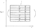
- FIG. 1 is a schematic section through the molded part 1 shown in an x / z plane of a motor vehicle.
- the molded part 1 is a structural part of a body of the motor vehicle according to the embodiment of the present invention.
- the molded part 1 consists of a multi-layer fiber composite material.
- the molded part 1 is a structurally supporting, thin-walled, over a large area extending body component.
- the multilayer structure of the molding 1 is symmetrical with respect to a center of the molding in the thickness direction.
- Fibers of the connecting layer 3 are unidirectional with an angle of 0 ° relative to the vehicle transverse direction, ie a Y-direction, formed.
- the fibers of the first support layer and the second support layer are also endless fibers arranged at an angle of 45 °.
- Adjacent to the first support layer 51 is a third support layer 53 whose fiber orientation is 0 °.
- Adjacent to the third support layer 53 is a fifth support layer 55, the fibers of which are arranged at an angle of 90 °.
- a seventh support layer 57 adjacent to the fifth support layer to a seventh support layer 57, whose fibers are arranged at 0 ° angle.
- a fourth support layer 54 adjacent to the second support layer 52, a fourth support layer 54, whose fibers are aligned at 0 ° angle.
- the fourth support layer 54 further adjoins a sixth support layer 56, whose fibers are formed at 90 ° angle.
- a eighth support layer 58 adjacent to the sixth support layer 56 an eighth support layer 58, the fibers are formed at 0 ° angle.
- the fibers of the backing layers are each unidirectionally aligned.
- 3 support layers are arranged in a symmetrical manner on both sides of the connecting layer.
- the molded part 1 in this case has a common polymeric matrix. That all supporting layers as well as the connecting layer 3 are formed by the same polymeric matrix.
- the fibers of the tie layer 3 are formed of such a material, so that fiber matrix adhesion of the fibers of the tie layer to the polymeric matrix is significantly less than fiber matrix adhesion of the fibers of the base layers to the polymeric matrix.
- the polymeric matrix consists of an epoxide.
- the fibers of the base layers are, for example, carbon fibers.
- the fibers of the bonding layer 3 are, for example, polyester fibers.
- a fiber matrix adhesion of a polyester fiber to the epoxy matrix is significantly less than a fiber matrix adhesion of the carbon fibers to the epoxy matrix.
- a transverse tensile strength of the respective layer is a measurable parameter. The transverse tensile strength is determined in a tensile test transverse to the fiber orientation.
- the molded part 1 is subjected to bending, as in FIG. 1 indicated by arrows, so first there is a layer separation of the first support layer 51 from the second support layer 52.
- a failure of the fibers fails in the connection layer 3, so that it may come to a relative movement between the first support layer 51 and the second support layer 52.
- This in turn means that in the bending stress and the associated initially elastic deformation of an elongation of the outermost support layers, in this case the eighth support layer 58 and the seventh support layer 57, significantly less than in the case in which no layer separation takes place.
- a possible deformation of the molded part 1 by bending can be increased by the fact that the first support layer 51 and the second support layer 52 can slide against each other when the connection layer 3 fails.
- the molded part which is a body component of a load-bearing crash structure of a motor vehicle body, may for example be a so-called front end wall 1.
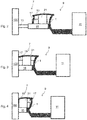
- FIG. 2 is shown, a front end wall 1 between a front end 7 and a passenger compartment 9 is arranged.
- FIG. 2 is a schematic side view of a typical passenger vehicle with a front end 7, a passenger compartment 9 and a rear carriage 11 shown.
- the passenger compartment 9 is arranged between the front car 7 and the rear carriage 11.
- the front end of the vehicle 7 is designed so that it can reduce sufficient collision energy in the event of a frontal collision of the motor vehicle with a collision opponent 100 to protect the passenger compartment 9 and provides a sufficient deformation path for reducing this collision energy.
- the crash structure of the front carriage 7 has, for example, as usual, a left deformation element and a right deformation element 13, which are also called crash boxes.
- the left deformation member 13 is connected to a left front engine mount 15 in alignment with the front end thereof.
- the right deformation element 13 is connected in alignment with a right front engine mount 15.
- a drive unit 17 is connected on the motor supports 15, a drive unit 17 is connected.
- the crash structure of the front end 17 include, for example, left and right wheel support supports 19 and left and right spring domes 21.
- the motor supports 15 are supported, among others, on the front end wall 1, which forms the molded part according to the invention.
- the front end wall 1 separates the front car 7 and the passenger compartment 9 from each other.
- FIG. 2 shows the state of a motor vehicle at a first time, namely a start of a frontal collision of the motor vehicle with the collision opponent 100, wherein no energy absorption and deceleration of the motor vehicle has yet taken place. There has not yet been any deformation of the crash structure.
- FIG. 3 Furthermore, a state of the motor vehicle in an advanced frontal collision is shown at a second time.
- the crash structure of the front carriage 7 has already been considerably deformed, in which case in particular the deformation elements 13 and the engine mounts 15 have been considerably deformed and have thereby contributed to a reduction of collision energy.
- the drive unit 17 is already directly or indirectly at the collision opponent 100 and has already been moved in the direction of the front end wall 1, so that a lock between collision opponent 100 and the front end wall 1 occurs because the drive unit 17 is substantially no Has deformation potential.
- a bending moment is applied to the end wall via the drive unit 17.
- the collision load pushes transversely to the planar extension of the end wall 1 against the end wall. 1
- FIG. 4 the deformation of the end wall 1 is shown by a bulging of the end wall 1 in the direction of the passenger compartment 9.
- the end wall 1 behaves like an elastic membrane, losing its resistance to bending due to the layer separation. As a result, further deformation path becomes free, so that the crash structure can further reduce collision energy through further deformation.
Landscapes
- Engineering & Computer Science (AREA)
- Mechanical Engineering (AREA)
- Chemical & Material Sciences (AREA)
- Combustion & Propulsion (AREA)
- Transportation (AREA)
- Architecture (AREA)
- Structural Engineering (AREA)
- Body Structure For Vehicles (AREA)
Description
- Die vorliegende Erfindung bezieht sich auf ein tragendes, flächiges Formteil aus einem Mehrschichtfaserverbundwerkstoff, insbesondere für eine Fahrzeugkarosserie, und eine Fahrzeugkarosserie mit einem derartigen Formteil.
- Die Offenlegungsschrift
DE 102012203727 A1 zeigt beispielsweise ein Wandelement, das aus einem faserverstärktem Kunststoff hergestellt ist. Ein derartiges Wandelement kann als Stirnwand in einer Kraftfahrzeugkarosserie eingesetzt sein, wobei die Stirnwand zwischen A-Säulen quer zu einer Fahrzeughauptfahrrichtung verläuft und einen Vorderwagenbereich von einem Hinterwagenbereich bzw. einen Motorraum von einem Fahrgastraum trennt. Eine derartige Stirnwand aus faserverstärktem Kunststoff hat den Vorteil, dass sie leicht ist, eine verhältnismäßig große Festigkeit aufweist und die Karosserie hinreichend gut versteift. - Faserverstärkte Kunststoffe, insbesondere mit Kohlenstofffaser verstärkte Kunststoffe, haben jedoch die Eigenschaft, dass sie eine verhältnismäßig geringe Verformbarkeit aufweisen, und bereits nach einem geringen Verformungsweg spröde versagen.
- Darüber hinaus ist es bekannt, in Kraftfahrzeugkarosserien aus Stahl oder Aluminium eine entsprechende metallische Stirnwand zwischen Vorderwagen und Fahrgastzelle einzusetzen. Eine derartige metallische Stirnwand ist gegenüber einem faserverstärkten Kunststoff bei gleicher Festigkeit wesentlich schwerer. Die metallische Stirnwand kann im Kollisionsfall über einen verhältnismäßig großen Weg plastisch verformt werden, bevor ein Reißen, d.h. ein endgültiges Versagen, der Stirnwand auftritt.
- Die Offenlegungsschrift
DE 39 34 555 A1 beschreibt ein faserverstärktes Sandwichlaminat für Strukturbauteile, insbesondere Karosserieteile von Kraftfahrzeugen. Es ist die Aufgabe der vorliegenden Erfindung, ein tragendes, flächiges Formteil bestehend aus einem Mehrschichtfaserverbundwerkstoff zu schaffen, das eine vergrößerte Verformbarkeit, insbesondere bei einer Biegebeanspruchung, aufweist. - Diese Aufgabe wird durch ein tragendes, flächiges Formteil gelöst, das die Merkmale von Patentanspruch 1 aufweist. Ferner wird diese Aufgabe durch eine Karosserie gelöst, die die Merkmale von Patentanspruch 11 aufweist. Vorteilhafte Weiterbildungen sind in den abhängigen Patentansprüchen aufgeführt.
- Insbesondere besteht ein tragendes, flächiges Formteil gemäß der vorliegenden Erfindung aus einem Mehrschichtfaserverbundwerkstoff. Beispielsweise ist das Formteil für eine Fahrzeugkarosserie als Bestandteil einer Crashstruktur des Fahrzeugs geeignet. Das Formteil weist zumindest eine erste Tragschicht und eine zweite Tragschicht auf, zwischen welchen angrenzend eine Verbindungsschicht angeordnet ist, die derart ausgebildet ist, dass bei einer Biegebeanspruchung des Formteils eine Schichttrennung zwischen der ersten Tragschicht und der zweiten Tragschicht erfolgt. Dabei weisen die Verbindungsschicht und die Tragschicht ein gemeinsames Matrixsystem auf. Die Mehrschichtigkeit bezieht sich also auf die mehreren Faserschichten, die in einem gemeinsamen Matrixsystem bzw. einer gemeinsamen Matrix eingebettet sind. Die Matrix ist dabei ein Werkstoff, insbesondere ein Kunststoff, in dem die Fasern eingebettet sind.
- Die genannte Schichttrennung erfolgt bevorzugt bei einer zuvor eingestellten Schwelllast bzw. Schwellbeanspruchung. Die Schichtrennung führt zu einer Verringerung der Biegesteifigkeit des flächigen Formteils, wobei gleichzeitig eine Membransteifigkeit des Formteils bestehen bleibt. Mit anderen Worten verhält sich das flächige Bauteil wie eine Membran, die innerhalb bestimmter Grenzen verformbar ist, jedoch nicht reißt. Das Formteil kann also Biegemomente bei einer größeren Verformbarkeit des Formteils aufnehmen. Das Formteil versagt damit verglichen mit dem Fall, in dem zwischen der ersten Tragschicht und der zweiten Tragschicht keine Schichttrennung erfolgen würde, erst nach einer größeren Verformung spröde. Bei dem Formteil eine Faser-Matrixhaftung in der Verbindungsschicht geringer als eine Faser-Matrixhaftung in den Tragschichten ausgebildet.
- Hierdurch versagt eine Faser-Matrixverbindung in der Verbindungsschicht früher als in der Tragschicht. Dadurch können sich die erste Tragschicht und die zweite Tragschicht relativ zueinander, insbesondere in der Ebene der Schichten, bewegen. Dies bedeutet, dass das Formteil insgesamt stärker gebogen werden kann, bis es vollständig spröde versagt.
- Insbesondere ist eine Querzugfestigkeit der Verbindungsschicht geringer als eine Querzugfestigkeit der Tragschicht. Die Querzugfestigkeit ist eine Festigkeit der Schicht quer zu einer Hauptfaserrichtung. Die Hauptfaserrichtung ist die Richtung, entlang der die Fasern zumindest überwiegend orientiert sind.
- Bevorzugt ist das Formteil ein dünnwandiges Formteil, so dass es zum Einen leichter ist und zum Anderen eine Verformbarkeit durch Biegung verbessert ist.
- Mit Verformbarkeit ist hier insbesondere eine elastische Verformbarkeit der Tragschichten gemeint. In der Verbindungsschicht tritt jedoch durch die Schichttrennung eher eine plastische Verformung bzw. ein plastisches Versagen ein.
- Gemäß einer weiteren bevorzugten Ausführungsform der vorliegenden Erfindung bestehen die Fasern der Verbindungsschicht aus einem anderen Material als die Fasern der Tragschichten.
- Hierdurch ist es möglich mit einfachen Mitteln eine unterschiedliche Fasermatrixhaftung zwischen Verbindungsschicht und Tragschichten herzustellen. Hierbei kommt es insbesondere auf die Materialpaarung Matrixsystem und Faser an.
- Gemäß einer weiteren bevorzugten Weiterbildung sind die Fasern der Verbindungsschicht derart oberflächenbehandelt, dass eine Fasermatrixhaftung zwischen den Fasern und der Matrix gegenüber nicht oberflächenbehandelten Fasern und der Matrix verringert ist. Eine derartige Oberflächenbehandlung kann sowohl bei einer Ausführungsform mit gleichen Faserwerkstoffen in den Tragschichten und der Verbindungsschicht als auch bei unterschiedlichen Faserwerkstoffen in den Tragschichten und der Verbindungsschicht durchgeführt sein.
- Hierdurch kann besonders einfach die Schichttrennung zwischen der ersten Tragschicht und der zweiten Tragschicht mit den bereits vorstehend erläuterten Vorteilen erfolgen.
- Alternativ oder zusätzlich können die Fasern der Tragschichten derart oberflächenbehandelt sein, so dass eine Haftung zwischen den Fasern und der Matrix gegenüber nicht oberflächenbehandelten Fasern und der Matrix erhöht ist.
- Bevorzugt sind die Fasern der Verbindungsschicht zur Verringerung der Fasermatrixhaftung beschichtet. Zusätzlich oder alternativ können die Fasern der Tragschichten zur Erhöhung der Fasermatrixhaftung beschichtet sein.
- Damit kann eine Beschichtung von Fasern der Verbindungsschicht und/oder der Tragschichten einen Unterschied in der Fasermatrixhaftung zwischen der Verbindungsschicht und den Tragschichten herbeiführen und hinreichend groß machen.
- Bevorzugt ist das Matrixsystem des Mehrschichtfaserverbundwerkstoffes ein polymeres Matrixsystem, d.h. ein Kunststoff. Das Matrixsystem kann ein duromeres Matrixsystem oder ein thermoplastisches Matrixsystem sein. Bevorzugt ist im Falle des duromeren Matrixsystems ein Epoxid. Ferner ist im Fall eines thermoplastischen Matrixsystems ein Polyurethan oder ein Polyester besonders bevorzugt.
- Hinsichtlich der Fasern sind in Bezug auf die Verbindungsschichten bevorzugt, überwiegend oder ausschließlich Polyesterfasern verwendet. Alternativ oder zusätzlich sind überwiegend oder ausschließlich Polyethylenfasern verwendet. Zusätzlich oder alternativ können die Tragschichten überwiegend oder ausschließlich Kohlenstofffasern enthalten. Alternativ oder zusätzlich können die Tragschichten überwiegend oder ausschließlich Aramidfasern enthalten. Ferner können die Tragschichten überwiegend oder ausschließlich Glasfasern enthalten.
- Eine besonders bevorzugte Materialpaarung ist ein Epoxid als Matrixsystem und Polyesterfasern in der Verbindungsschicht sowie Kohlenstofffasern in den Tragschichten.
- Bevorzugt liegen in den Formteilen die Fasern in dem Mehrschichtverbundwerkstoff im Wesentlichen parallel zur flächigen Erstreckung des Bauteils vor.
- Bevorzugt sind die Fasern des Mehrschichtverbundwerkstoffs im Wesentlichen Endlosfasern.
- Ferner sind die Fasern bevorzugt in jeder Schicht im Wesentlichen unidirektional angeordnet, wobei die Fasern unterschiedlicher Schichten durchaus in unterschiedlichen Richtungen ausgerichtet sein können.
- Besonders bevorzugt ist das Formteil in Dickenrichtung symmetrisch aufgebaut. Damit ist die Verbindungsschicht im Bezug auf die Dickenrichtung in der Mitte des Bauteils angeordnet. Diese Ausführung ermöglicht eine größtmögliche Verformbarkeit des Formteils durch die Biegebeanspruchung.
- Gemäß einer Weiterbildung kann das Formteil weitere Tragschichten aufweisen. Insbesondere kann angrenzend zu der ersten Tragschicht eine weitere Tragschicht angeordnet sein. Ferner kann angrenzend zu der zweiten Tragschicht eine weitere Tragschicht angeordnet sein. Angrenzend zu den weiteren Tragschichten können wiederum ebenso weitere Tragschichten angeordnet sein. Im Falle, dass es mehr als zwei Tragschichten gibt, können auch weitere Verbindungsschichten angeordnet sein, wobei eine Verbindungsschicht immer zumindest zwischen zwei Tragschichten angeordnet ist.
- Bevorzugt ist das Formteil eine Wand zum Einbau in eine Fahrzeugkarosserie. Die Wand kann beispielsweise eine Stirnwand sein, die sich im eingebauten Zustand quer zu einer Fahrzeughauptfahrrichtung erstreckt und zwischen einem Vorderwagen und einer Fahrgastzelle angeordnet ist. Insbesondere kann sich die Wand zwischen einer linken und einer rechten A-Säule erstrecken.
- Die Wand ist dabei bevorzugt derart ausgebildet, dass sie sich durch eine Kollisionslast durch eine Frontalkollision des Kraftfahrzeugs in Richtung der Fahrgastzelle durch vorstehend beschriebene Schichttrennung hinreichend in Richtung der Fahrgastzelle verformen kann, ohne dass sie vollständig spröde versagt.
- Die vorliegende Erfindung bezieht sich ferner auf eine Kraftfahrzeugkarosserie, die ein erfindungsgemäßes Formteil aufweist.
- Vorstehend beschriebene Weiterbildungen der Erfindung können soweit möglich und sinnvoll beliebig miteinander kombiniert werden.
- Es folgt eine Kurzbeschreibung der Figuren.
- Fig. 1
- ist eine schematische Ansicht eines Schichtaufbaus eines Formteils gemäß einem Ausführungsbeispiel der vorliegenden Erfindung.
- Fig. 2
- ist eine schematische Seitenansicht eines Kraftfahrzeugs mit dem Formteil gemäß dem Ausführungsbeispiel der vorliegenden Erfindung zu einem Beginn einer Frontalkollision.
- Fig. 3
- ist eine schematische Seitenansicht des Kraftfahrzeugs mit dem Formteil gemäß dem Ausführungsbeispiel der vorliegenden Erfindung im weiteren Verlauf der Frontalkollision zu einem zweiten Zeitpunkt der Frontalkollision.
- Fig. 4
- ist eine schematische Seitenansicht des Kraftfahrzeugs mit dem Formteil gemäß dem Ausführungsbeispiel der vorliegenden Erfindung zu einem dritten Zeitpunkt der Frontalkollision, bei dem das Formteil verformt wurde.
- Nachstehend ist ein Ausführungsbeispiel der vorliegenden Erfindung unter Bezugnahme auf die Figuren beschrieben.
- In
Figur 1 ist ein prinzipieller Schnitt durch das Formteil 1 in einer x/z-Ebene eines Kraftfahrzeugs gezeigt. Das Formteil 1 ist struktureller Bestandteil einer Karosserie des Kraftfahrzeugs gemäß dem Ausführungsbeispiel der vorliegenden Erfindung. Das Formteil 1 besteht aus einem Mehrschichtfaserverbundwerkstoff. Das Formteil 1 ist ein strukturell tragendes, dünnwandiges, sich über eine große Fläche erstreckendes Karosseriebauteil. Der Mehrschichtaufbau des Formteils 1 ist symmetrisch im Bezug auf eine Mitte des Formteils in Dickenrichtung. In der Mitte des Formteils 1 befindet sich eine Verbindungsschicht 3. Angrenzend an die Verbindungsschicht 3 sind eine erste Tragschicht 51 und eine zweite Tragschicht 52 angeordnet. Fasern der Verbindungsschicht 3 sind unidirektional mit einem Winkel von 0° gegenüber der Fahrzeugquerrichtung, also einer Y-Richtung, ausgebildet. Die Fasern der ersten Tragschicht und der zweiten Tragschicht sind ebenso Endlosfasern, die in einem Winkel von 45° angeordnet sind. An die erste Tragschicht 51 grenzt eine dritte Tragschicht 53 an, deren Faserausrichtung 0° beträgt. An die dritte Tragschicht 53 grenzt eine fünfte Tragschicht 55 an, deren Fasern im 90° Winkel angeordnet sind. Darüber hinaus grenzt an die fünfte Tragschicht eine siebte Tragschicht 57 an, deren Fasern im 0° Winkel angeordnet sind. Analog grenzt an die zweite Tragschicht 52 eine vierte Tragschicht 54 an, deren Fasern im 0° Winkel ausgerichtet sind. An die vierte Tragschicht 54 grenzt ferner eine sechste Tragschicht 56 an, deren Fasern im 90° Winkel ausgebildet sind. Darüber hinaus grenzt an die sechste Tragschicht 56 eine achte Tragschicht 58 an, deren Fasern im 0° Winkel ausgebildet sind. Ebenso wie bei der Verbindungsschicht 3 sind die Fasern der Tragschichten jeweils unidirektional ausgerichtet. Insgesamt sind auf beiden Seiten der Verbindungsschicht 3 Tragschichten in symmetrischer Art und Weise angeordnet. - Das Formteil 1 weist dabei eine gemeinsame polymere Matrix auf. D.h. alle Tragschichten sowie die Verbindungsschicht 3 sind durch dieselbe polymere Matrix gebildet. Die Fasern der Verbindungsschicht 3 sind aus einem derartigen Werkstoff ausgebildet bzw. sind derart oberflächenbehandelt, so dass eine Fasermatrixhaftung der Fasern der Verbindungsschicht mit der polymeren Matrix erheblich geringer ist als eine Fasermatrixhaftung der Fasern der Tragschichten mit der polymeren Matrix.
- Beispielsweise besteht die polymere Matrix aus einem Epoxid. Die Fasern der Tragschichten sind beispielsweise Kohlenstofffasern. Die Fasern der Verbindungsschicht 3 sind demgegenüber beispielsweise Polyesterfasern. Eine Fasermatrixhaftung einer Polyesterfaser mit der Epoxidmatrix ist erheblich geringer als eine Fasermatrixhaftung der Kohlenstofffasern mit der Epoxidmatrix. Bei einer geringen Fasermatrixhaftung ist eine Querzugfestigkeit der jeweiligen Schicht ein messbarer Parameter. Die Querzugfestigkeit wird in einem Zugversuch quer zur Faserausrichtung ermittelt.
- Wird nun das Formteil 1 auf Biegung beansprucht, so wie in
Figur 1 durch Pfeile angedeutet ist, so erfolgt zunächst eine Schichttrennung der ersten Tragschicht 51 von der zweiten Tragschicht 52. Insbesondere versagt eine Haftung der Fasern in der Verbindungsschicht 3, so dass es zu einer Relativbewegung zwischen der ersten Tragschicht 51 und der zweiten Tragschicht 52 kommen kann. Dies führt wiederum dazu, dass bei der Biegebeanspruchung und der damit einhergehenden zunächst elastischen Verformung eine Dehnung der äußersten Tragschichten, hier also der achten Tragschicht 58 und der siebten Tragschicht 57, deutlich geringer als in dem Fall ausfällt, in dem keine Schichttrennung stattfindet. - Insgesamt kann eine mögliche Verformung des Formteils 1 durch Biegung dadurch vergrößert werden, dass die erste Tragschicht 51 und die zweite Tragschicht 52 gegeneinander gleiten können, wenn die Verbindungsschicht 3 versagt.
- Das Formteil, das ein Karosseriebauteil einer tragenden Crashstruktur einer Kraftfahrzeugkarosserie ist, kann beispielsweise eine sogenannte vordere Stirnwand 1 sein.
- Wie in
Figur 2 gezeigt ist, ist eine vordere Stirnwand 1 zwischen einem Vorderwagen 7 und einer Fahrgastzelle 9 angeordnet. InFigur 2 ist eine schematische Seitenansicht eines typischen Personenkraftfahrzeugs mit einem Vorderwagen 7, einer Fahrgastzelle 9 und einem Hinterwagen 11 gezeigt. Die Fahrgastzelle 9 ist zwischen dem Vorderwagen 7 und dem Hinterwagen 11 angeordnet. Der Vorderwagen 7 ist derart ausgestaltet, dass er im Fall einer frontalen Kollision des Kraftfahrzeugs mit einem Kollisionsgegner 100 zum Schutz der Fahrgastzelle 9 hinreichend Kollisionsenergie abbauen kann und einen hinreichenden Deformationsweg zum Abbau dieser Kollisionsenergie zur Verfügung stellt. Die Crashstruktur des Vorderwagens 7 weist beispielsweise wie üblicherweise ein linkes Deformationselement und ein rechtes Deformationselement 13 auf, die auch Crashboxen genannt werden. Das linke Deformationselement 13 ist mit einem linken vorderen Motorträger 15 fluchtend an dessen vorderen Ende verbunden. Ebenso ist das rechte Deformationselement 13 mit einem rechten vorderen Motorträger 15 fluchtend verbunden. An den Motorträgern 15 ist eine Antriebseinheit 17 angebunden. Ferner zählen zur Crashstruktur des Vorderwagens 17 beispielswiese linke und rechte Radhausstützträger 19 sowie linke und rechte Federdome 21. Die Motorträger 15 stützten sich unter anderen an der vorderen Stirnwand 1 ab, die das erfindungsgemäße Formteil bildet. Die vordere Stirnwand 1 trennt den Vorderwagen 7 und die Fahrgastzelle 9 voneinander. - Im Folgenden ist eine Funktion der vorderen Stirnwand 1 des Kraftfahrzeugs gemäß dem Ausführungsbeispiel der vorliegenden Erfindung unter Bezugnahme auf
Figuren 2 bis 4 erläutert. - Insbesondere zeigt
Figur 2 den Zustand eines Kraftfahrzeugs zu einem ersten Zeitpunkt, nämlich einem Beginn einer Frontalkollision des Kraftfahrzeugs mit dem Kollisionsgegner 100, wobei noch keine Energieabsorption und Verzögerung des Kraftfahrzeugs stattgefunden hat. Es hat noch keinerlei Verformung der Crashstruktur stattgefunden. - In
Figur 3 ist ferner ein Zustand des Kraftfahrzeugs bei fortgeschrittener Frontalkollision zu einem zweiten Zeitpunkt gezeigt. Zu dem zweiten Zeitpunkt ist die Crashstruktur des Vorderwagens 7 schon erheblich verformt worden, wobei insbesondere die Deformationselemente 13 und die Motorträger 15 erheblich verformt wurden und dabei zu einem Abbau von Kollisionsenergie beigetragen haben. Ferner liegt zu dem zweiten Zeitpunkt die Antriebseinheit 17 bereits mittelbar oder unmittelbar an dem Kollisionsgegner 100 an und wurde bereits in Richtung der vorderen Stirnwand 1 verschoben, so dass eine Verblockung zwischen Kollisionsgegner 100 und der vorderen Stirnwand 1 eintritt, da die Antriebseinheit 17 im Wesentlichen kein Verformungspotential aufweist. Dies führt dazu, dass über die Antriebseinheit 17 ein Biegemoment auf die Stirnwand aufgegeben wird. Insbesondere drückt die Kollisionslast quer zu der flächigen Erstreckung der Stirnwand 1 gegen die Stirnwand 1. - Sobald eine vorbestimmte Last überschritten ist, findet in der vorderen Stirnwand 1 eine Schichttrennung zwischen der ersten Tragschicht 51 und der zweiten Tragschicht 52 statt, so dass die Stirnwand 1 deutlich stärker verformt werden kann, bevor sie vollständig spröde versagt, als wenn keine Schichttrennung zwischen der ersten Tragschicht 51 und der zweiten Tragschicht 52 stattfinden würde.
- In
Figur 4 ist das Verformen der Stirnwand 1 über ein Ausbeulen der Stirnwand 1 in Richtung der Fahrgastzelle 9 dargestellt. - Die Stirnwand 1 verhält sich in bestimmten Grenzen also wie eine elastische Membran, wobei sie durch die Schichttrennung an Biegefestigkeit verliert. Es wird hierdurch weiterer Deformationsweg frei, so dass die Crashstruktur durch weitere Verformung weiter Kollisionsenergie abbauen kann.
- Insgesamt ist es dadurch möglich, einen kürzeren Vorderwagen vorzusehen, der trotzdem Erfordernisse eines Kollisionslastfalls bei einer Frontalkollision erfüllten kann.
- Durch die Schichttrennung wird zwar eine Biegesteifigkeit bzw. ein Biegewiderstand der Stirnwand reduziert, die Zugeigenschaften der Tragschichten, insbesondere der äußersten Tragschichten, bleiben davon aber unberührt.
Claims (11)
- Tragendes, flächiges Formteil (1) bestehend aus einem Mehrschichtfaserverbundwerkstoff, wobei das Formteil (1) zumindest eine erste Tragschicht (51) und eine zweite Tragschicht (52) aufweist, zwischen welchen angrenzend eine Verbindungsschicht (3) angeordnet ist, wobei die Verbindungsschicht (3) und die Tragschichten (51, 52) ein gemeinsames Matrixsystem aufweisen,
dadurch gekennzeichnet, dass
die Verbindungsschicht (3) derart ausgebildet ist, dass bei einer Biegebeanspruchung des Formteils (1) eine Schichttrennung zwischen der ersten Tragschicht (51) und der zweiten Tragschicht (52) erfolgt, und wobei eine Fasermatrixhaftung in der Verbindungsschicht (3) geringer als eine Fasermatrixhaftung in den Tragschichten (51, 52) ausgebildet ist, und insbesondere eine Querzugfestigkeit der Verbindungsschicht (3) geringer als eine Querzugfestigkeit der Tragschichten (51, 52) ist. - Formteil nach Patentanspruch 1, wobei die Fasern der Verbindungsschicht (3) aus einem anderen Material als die Fasern der Tragschichten (51, 52) bestehen.
- Formteil nach einem der Patentansprüche 1 oder 2, wobei die Fasern der Verbindungsschicht (3) zur Verringerung der Fasermatrixhaftung oberflächenbehandelt sind oder/und die Fasern der Tragschichten (51, 52) zur Erhöhung der Fasermatrixhaftung oberflächenbehandelt sind.
- Formteil nach Patentanspruch 3, wobei die Fasern der Verbindungsschicht (3) zur Verringerung der Fasermatrixhaftung beschichtet sind oder/und die Fasern der Tragschichten (51, 52) zur Erhöhung der Fasermatrixhaftung beschichtet sind.
- Formteil nach einem der Patentansprüche 1 bis 4, wobei der Mehrschichtfaserverbundwerkstoff ein polymeres Matrixsystem, insbesondere ein duromeres Matrixsystem, beispielsweise Epoxid, oder ein thermoplastisches Matrixsystem, beispielsweise Polyurethan oder Polyester, aufweist.
- Formteil nach einem der Patentansprüche 1 bis 5, wobei die Verbindungsschicht (3) überwiegend oder ausschließlich Polyesterfasern und/oder überwiegend oder ausschließlich Polyethylenfasern enthält und/oder wobei die Tragschichten (51, 52) überwiegend oder ausschließlich Kohlenstoff-Fasern, oder überwiegend oder ausschließlich Aramidfasern, oder überwiegend oder ausschließlich Glasfasern enthalten.
- Formteil nach einem der Patentansprüche 1 bis 6, wobei die Fasern in dem Mehrschichtverbundwerkstoff im Wesentlichen parallel zur flächigen Erstreckung des Formteils (1) ausgerichtet sind, und/oder wobei die Fasern im Wesentlichen Endlosfasern sind, und/oder wobei die Fasern in jeder Schicht im Wesentlichen unidirektional angeordnet sind.
- Formteil nach einem der Patentansprüche 1 bis 7, wobei das Formteil (1) in Richtung seiner Dicke symmetrisch aufgebaut ist, und wobei insbesondere die Verbindungsschicht (3) in Richtung seiner Dicke in der Mitte angeordnet ist.
- Formteil nach einem der Patentansprüche 1 bis 8, wobei das Formteil (1) weitere Tragschichten (53, 54, 55, 56, 57, 58) und/oder weitere Verbindungsschichten aufweist.
- Formteil nach einem der Patentansprüche 1 bis 9, wobei das Formteil eine Wand (1) zum Einbau in einer Fahrzeugkarosserie ist, die sich in eingebauten Zustand quer zu einer Fahrzeughauptfahrrichtung zwischen einem Vorderwagen (7) und einer Fahrgastzelle (9) erstreckt, und wobei sich die Wand (1) insbesondere zwischen A-Säulen erstreckt.
- Karosserie für ein Kraftfahrzeug mit einem Formteil nach einem der Patentansprüche 1 bis 10, wobei das Formteil (1) Bestandteil einer Crashstruktur des Kraftfahrzeugs ist und derart ausgelegt ist, dass in einem Kollisionslastfall eine Biegesteifigkeit des Formteils (1) durch die Schichttrennung verringert wird, so dass eine größere Verformung des Formteils möglich ist.
Applications Claiming Priority (2)
| Application Number | Priority Date | Filing Date | Title |
|---|---|---|---|
| DE102013224927.6A DE102013224927A1 (de) | 2013-12-04 | 2013-12-04 | Tragendes, flächiges Formteil aus einem Mehrschichtfaserverbundwerkstoff, insbesondere für eine Fahrzeugkarosserie |
| PCT/EP2014/076099 WO2015082398A1 (de) | 2013-12-04 | 2014-12-01 | Tragendes, flächiges formteil aus einem mehrschichtfaserverbundwerkstoff, insbesondere für eine fahrzeugkarosserie |
Publications (2)
| Publication Number | Publication Date |
|---|---|
| EP3077202A1 EP3077202A1 (de) | 2016-10-12 |
| EP3077202B1 true EP3077202B1 (de) | 2018-07-25 |
Family
ID=52002956
Family Applications (1)
| Application Number | Title | Priority Date | Filing Date |
|---|---|---|---|
| EP14805897.7A Not-in-force EP3077202B1 (de) | 2013-12-04 | 2014-12-01 | Tragendes, flächiges formteil aus einem mehrschichtfaserverbundwerkstoff, insbesondere für eine fahrzeugkarosserie |
Country Status (3)
| Country | Link |
|---|---|
| EP (1) | EP3077202B1 (de) |
| DE (1) | DE102013224927A1 (de) |
| WO (1) | WO2015082398A1 (de) |
Families Citing this family (2)
| Publication number | Priority date | Publication date | Assignee | Title |
|---|---|---|---|---|
| KR101836710B1 (ko) * | 2016-10-04 | 2018-03-09 | 현대자동차주식회사 | 차량용 후드 및 그 제조방법 |
| CN112644589A (zh) * | 2020-12-31 | 2021-04-13 | 杭州卡涞复合材料科技有限公司 | 一种连续纤维复合材料汽车前引擎盖内板折弯结构的铺层设计方法 |
Family Cites Families (9)
| Publication number | Priority date | Publication date | Assignee | Title |
|---|---|---|---|---|
| DE8607213U1 (de) * | 1986-03-15 | 1986-06-26 | ComTec Ingenieurbüro für Verbundwerkstoffe GmbH, 5100 Aachen | Sandwich-Plattenelement |
| JPS6431835A (en) * | 1987-07-28 | 1989-02-02 | Kuraray Co | Fiber-reinforced polymer molded article |
| DE3934555A1 (de) * | 1989-10-17 | 1991-04-18 | Audi Ag | Faserverstaerktes sandwichlaminat fuer hochbeanspruchbare, hochsteife, flaechige strukturbauteile, insbesondere karosserieteile von kraftfahrzeugen |
| US5514448A (en) * | 1992-07-22 | 1996-05-07 | Mitsui Toatsu Chemicals, Inc. | Laminated molding |
| FR2732300B1 (fr) * | 1995-03-28 | 1997-04-30 | Peugeot | Structure de vehicule automobile et vehicule automobile comportant une telle structure |
| DE10351181A1 (de) * | 2003-11-03 | 2005-06-02 | Dr.Ing.H.C. F. Porsche Ag | Wand für einen Aufbau eines Kraftfahrzeugs |
| DE102007025631A1 (de) * | 2007-06-01 | 2008-12-11 | Audi Ag | Faserverbundwerkstoffprofil und Kraftfahrzeugscheibenrahmen |
| JP5255831B2 (ja) * | 2007-12-27 | 2013-08-07 | 株式会社デルタツーリング | 衝撃吸収構造体、シェル型フレーム部材及び座席構造 |
| DE102012203727A1 (de) | 2012-03-09 | 2013-09-12 | Bayerische Motoren Werke Aktiengesellschaft | Kabelanordnung an einem Wandelement eines Fahrzeugs |
-
2013
- 2013-12-04 DE DE102013224927.6A patent/DE102013224927A1/de not_active Withdrawn
-
2014
- 2014-12-01 WO PCT/EP2014/076099 patent/WO2015082398A1/de not_active Ceased
- 2014-12-01 EP EP14805897.7A patent/EP3077202B1/de not_active Not-in-force
Non-Patent Citations (1)
| Title |
|---|
| None * |
Also Published As
| Publication number | Publication date |
|---|---|
| EP3077202A1 (de) | 2016-10-12 |
| WO2015082398A1 (de) | 2015-06-11 |
| DE102013224927A1 (de) | 2015-06-11 |
Similar Documents
| Publication | Publication Date | Title |
|---|---|---|
| EP2331318B1 (de) | Faserverbundbauteil zur energieabsorption im crash-fall für ein luft- oder raumfahrzeug, rumpfstrukturabschnitt eines luft- oder raumfahrzeugs und luft- oder raumfahrzeug | |
| DE102017207883B4 (de) | Stoßdämpfende Verstärkungsstruktur für B-Säulen | |
| DE102013102502B4 (de) | Kraftfahrzeug mit einem Schutzprofil | |
| DE102015207376A1 (de) | Kraftfahrzeug | |
| EP1336470B1 (de) | Konstruktionselement aus faserverstärktem Kunststoff | |
| WO2012126923A1 (de) | Verbundwerkstoff und strukturbauteil für ein kraftfahrzeug | |
| EP1867559A2 (de) | Aufprallschutzverstärkungsteil | |
| WO2015091240A1 (de) | Karosseriestruktur in knotenbauweise | |
| DE102017006057B4 (de) | Crashelement | |
| WO2016142517A1 (de) | Fahrzeugkomponente mit zumindest einem sandwich-bauteil | |
| EP2999616B1 (de) | Achsträger eines fahrzeugs | |
| WO2012055489A1 (de) | Elastische lagerung für ein bauteil und verfahren zu deren herstellung | |
| DE102015008261A1 (de) | Aufprallträger, Seitentür und Fahrzeug | |
| WO2015090526A1 (de) | Unterbodenaussteifungs- und verkleidungsmodul | |
| EP3445640B1 (de) | Strukturbauteil | |
| DE102016123352A1 (de) | Aufprallabsorptionseinheit, Herstellungsverfahren der Aufprallabsorptionseinheit und Aufprallabsorptionsverstärkung | |
| EP3077202B1 (de) | Tragendes, flächiges formteil aus einem mehrschichtfaserverbundwerkstoff, insbesondere für eine fahrzeugkarosserie | |
| DE102021108564B4 (de) | Bauteil eines Kraftfahrzeugs | |
| DE102016204624B4 (de) | Sandwich-Verbundbauteil zur Verwendung als Ladeboden oder Hutablage eines Kraftfahrzeuges | |
| DE102010027354A1 (de) | Tragstruktur einer Fahrzeugkarosserie | |
| DE10253300A1 (de) | Faserverstärkter Verbundkunststoff zur Herstellung von Strukturbauteilen, Strukturbauteile aus einem derartigen Verbundkunststoff sowie Verfahren zur Herstellung von faserverstärkten Strukturbauteilen | |
| EP3083208B1 (de) | Akustik-kabinenpaneel und verfahren zur herstellung eines akustik-kabinenpaneels | |
| EP1997721B1 (de) | Faserverbundwerkstoffprofil und Kraftfahrzeugscheibenrahmen | |
| EP1997716B1 (de) | Faserverbundwerkstoffprofil und Kraftfahrzeugscheibenrahmen | |
| DE102009023033B4 (de) | Verfahren zur Herstellung eines Halbzeugs für eine Bodenstruktur |
Legal Events
| Date | Code | Title | Description |
|---|---|---|---|
| PUAI | Public reference made under article 153(3) epc to a published international application that has entered the european phase |
Free format text: ORIGINAL CODE: 0009012 |
|
| 17P | Request for examination filed |
Effective date: 20160624 |
|
| AK | Designated contracting states |
Kind code of ref document: A1 Designated state(s): AL AT BE BG CH CY CZ DE DK EE ES FI FR GB GR HR HU IE IS IT LI LT LU LV MC MK MT NL NO PL PT RO RS SE SI SK SM TR |
|
| AX | Request for extension of the european patent |
Extension state: BA ME |
|
| DAX | Request for extension of the european patent (deleted) | ||
| GRAP | Despatch of communication of intention to grant a patent |
Free format text: ORIGINAL CODE: EPIDOSNIGR1 |
|
| INTG | Intention to grant announced |
Effective date: 20180326 |
|
| GRAS | Grant fee paid |
Free format text: ORIGINAL CODE: EPIDOSNIGR3 |
|
| GRAA | (expected) grant |
Free format text: ORIGINAL CODE: 0009210 |
|
| AK | Designated contracting states |
Kind code of ref document: B1 Designated state(s): AL AT BE BG CH CY CZ DE DK EE ES FI FR GB GR HR HU IE IS IT LI LT LU LV MC MK MT NL NO PL PT RO RS SE SI SK SM TR |
|
| REG | Reference to a national code |
Ref country code: GB Ref legal event code: FG4D Free format text: NOT ENGLISH |
|
| REG | Reference to a national code |
Ref country code: CH Ref legal event code: EP |
|
| REG | Reference to a national code |
Ref country code: AT Ref legal event code: REF Ref document number: 1021311 Country of ref document: AT Kind code of ref document: T Effective date: 20180815 |
|
| REG | Reference to a national code |
Ref country code: IE Ref legal event code: FG4D Free format text: LANGUAGE OF EP DOCUMENT: GERMAN |
|
| REG | Reference to a national code |
Ref country code: DE Ref legal event code: R096 Ref document number: 502014008987 Country of ref document: DE |
|
| REG | Reference to a national code |
Ref country code: NL Ref legal event code: MP Effective date: 20180725 |
|
| REG | Reference to a national code |
Ref country code: LT Ref legal event code: MG4D |
|
| PG25 | Lapsed in a contracting state [announced via postgrant information from national office to epo] |
Ref country code: NL Free format text: LAPSE BECAUSE OF FAILURE TO SUBMIT A TRANSLATION OF THE DESCRIPTION OR TO PAY THE FEE WITHIN THE PRESCRIBED TIME-LIMIT Effective date: 20180725 |
|
| PG25 | Lapsed in a contracting state [announced via postgrant information from national office to epo] |
Ref country code: BG Free format text: LAPSE BECAUSE OF FAILURE TO SUBMIT A TRANSLATION OF THE DESCRIPTION OR TO PAY THE FEE WITHIN THE PRESCRIBED TIME-LIMIT Effective date: 20181025 Ref country code: LT Free format text: LAPSE BECAUSE OF FAILURE TO SUBMIT A TRANSLATION OF THE DESCRIPTION OR TO PAY THE FEE WITHIN THE PRESCRIBED TIME-LIMIT Effective date: 20180725 Ref country code: PL Free format text: LAPSE BECAUSE OF FAILURE TO SUBMIT A TRANSLATION OF THE DESCRIPTION OR TO PAY THE FEE WITHIN THE PRESCRIBED TIME-LIMIT Effective date: 20180725 Ref country code: IS Free format text: LAPSE BECAUSE OF FAILURE TO SUBMIT A TRANSLATION OF THE DESCRIPTION OR TO PAY THE FEE WITHIN THE PRESCRIBED TIME-LIMIT Effective date: 20181125 Ref country code: GR Free format text: LAPSE BECAUSE OF FAILURE TO SUBMIT A TRANSLATION OF THE DESCRIPTION OR TO PAY THE FEE WITHIN THE PRESCRIBED TIME-LIMIT Effective date: 20181026 Ref country code: NO Free format text: LAPSE BECAUSE OF FAILURE TO SUBMIT A TRANSLATION OF THE DESCRIPTION OR TO PAY THE FEE WITHIN THE PRESCRIBED TIME-LIMIT Effective date: 20181025 Ref country code: SE Free format text: LAPSE BECAUSE OF FAILURE TO SUBMIT A TRANSLATION OF THE DESCRIPTION OR TO PAY THE FEE WITHIN THE PRESCRIBED TIME-LIMIT Effective date: 20180725 Ref country code: RS Free format text: LAPSE BECAUSE OF FAILURE TO SUBMIT A TRANSLATION OF THE DESCRIPTION OR TO PAY THE FEE WITHIN THE PRESCRIBED TIME-LIMIT Effective date: 20180725 Ref country code: FI Free format text: LAPSE BECAUSE OF FAILURE TO SUBMIT A TRANSLATION OF THE DESCRIPTION OR TO PAY THE FEE WITHIN THE PRESCRIBED TIME-LIMIT Effective date: 20180725 |
|
| PG25 | Lapsed in a contracting state [announced via postgrant information from national office to epo] |
Ref country code: HR Free format text: LAPSE BECAUSE OF FAILURE TO SUBMIT A TRANSLATION OF THE DESCRIPTION OR TO PAY THE FEE WITHIN THE PRESCRIBED TIME-LIMIT Effective date: 20180725 Ref country code: AL Free format text: LAPSE BECAUSE OF FAILURE TO SUBMIT A TRANSLATION OF THE DESCRIPTION OR TO PAY THE FEE WITHIN THE PRESCRIBED TIME-LIMIT Effective date: 20180725 Ref country code: LV Free format text: LAPSE BECAUSE OF FAILURE TO SUBMIT A TRANSLATION OF THE DESCRIPTION OR TO PAY THE FEE WITHIN THE PRESCRIBED TIME-LIMIT Effective date: 20180725 |
|
| REG | Reference to a national code |
Ref country code: DE Ref legal event code: R097 Ref document number: 502014008987 Country of ref document: DE |
|
| PG25 | Lapsed in a contracting state [announced via postgrant information from national office to epo] |
Ref country code: EE Free format text: LAPSE BECAUSE OF FAILURE TO SUBMIT A TRANSLATION OF THE DESCRIPTION OR TO PAY THE FEE WITHIN THE PRESCRIBED TIME-LIMIT Effective date: 20180725 Ref country code: IT Free format text: LAPSE BECAUSE OF FAILURE TO SUBMIT A TRANSLATION OF THE DESCRIPTION OR TO PAY THE FEE WITHIN THE PRESCRIBED TIME-LIMIT Effective date: 20180725 Ref country code: CZ Free format text: LAPSE BECAUSE OF FAILURE TO SUBMIT A TRANSLATION OF THE DESCRIPTION OR TO PAY THE FEE WITHIN THE PRESCRIBED TIME-LIMIT Effective date: 20180725 Ref country code: RO Free format text: LAPSE BECAUSE OF FAILURE TO SUBMIT A TRANSLATION OF THE DESCRIPTION OR TO PAY THE FEE WITHIN THE PRESCRIBED TIME-LIMIT Effective date: 20180725 Ref country code: ES Free format text: LAPSE BECAUSE OF FAILURE TO SUBMIT A TRANSLATION OF THE DESCRIPTION OR TO PAY THE FEE WITHIN THE PRESCRIBED TIME-LIMIT Effective date: 20180725 |
|
| PG25 | Lapsed in a contracting state [announced via postgrant information from national office to epo] |
Ref country code: SM Free format text: LAPSE BECAUSE OF FAILURE TO SUBMIT A TRANSLATION OF THE DESCRIPTION OR TO PAY THE FEE WITHIN THE PRESCRIBED TIME-LIMIT Effective date: 20180725 Ref country code: SK Free format text: LAPSE BECAUSE OF FAILURE TO SUBMIT A TRANSLATION OF THE DESCRIPTION OR TO PAY THE FEE WITHIN THE PRESCRIBED TIME-LIMIT Effective date: 20180725 Ref country code: DK Free format text: LAPSE BECAUSE OF FAILURE TO SUBMIT A TRANSLATION OF THE DESCRIPTION OR TO PAY THE FEE WITHIN THE PRESCRIBED TIME-LIMIT Effective date: 20180725 |
|
| PLBE | No opposition filed within time limit |
Free format text: ORIGINAL CODE: 0009261 |
|
| STAA | Information on the status of an ep patent application or granted ep patent |
Free format text: STATUS: NO OPPOSITION FILED WITHIN TIME LIMIT |
|
| 26N | No opposition filed |
Effective date: 20190426 |
|
| REG | Reference to a national code |
Ref country code: CH Ref legal event code: PL |
|
| PG25 | Lapsed in a contracting state [announced via postgrant information from national office to epo] |
Ref country code: SI Free format text: LAPSE BECAUSE OF FAILURE TO SUBMIT A TRANSLATION OF THE DESCRIPTION OR TO PAY THE FEE WITHIN THE PRESCRIBED TIME-LIMIT Effective date: 20180725 Ref country code: MC Free format text: LAPSE BECAUSE OF FAILURE TO SUBMIT A TRANSLATION OF THE DESCRIPTION OR TO PAY THE FEE WITHIN THE PRESCRIBED TIME-LIMIT Effective date: 20180725 Ref country code: LU Free format text: LAPSE BECAUSE OF NON-PAYMENT OF DUE FEES Effective date: 20181201 |
|
| REG | Reference to a national code |
Ref country code: IE Ref legal event code: MM4A |
|
| REG | Reference to a national code |
Ref country code: BE Ref legal event code: MM Effective date: 20181231 |
|
| PG25 | Lapsed in a contracting state [announced via postgrant information from national office to epo] |
Ref country code: IE Free format text: LAPSE BECAUSE OF NON-PAYMENT OF DUE FEES Effective date: 20181201 |
|
| PG25 | Lapsed in a contracting state [announced via postgrant information from national office to epo] |
Ref country code: BE Free format text: LAPSE BECAUSE OF NON-PAYMENT OF DUE FEES Effective date: 20181231 |
|
| PG25 | Lapsed in a contracting state [announced via postgrant information from national office to epo] |
Ref country code: LI Free format text: LAPSE BECAUSE OF NON-PAYMENT OF DUE FEES Effective date: 20181231 Ref country code: CH Free format text: LAPSE BECAUSE OF NON-PAYMENT OF DUE FEES Effective date: 20181231 |
|
| PG25 | Lapsed in a contracting state [announced via postgrant information from national office to epo] |
Ref country code: MT Free format text: LAPSE BECAUSE OF FAILURE TO SUBMIT A TRANSLATION OF THE DESCRIPTION OR TO PAY THE FEE WITHIN THE PRESCRIBED TIME-LIMIT Effective date: 20180725 |
|
| PG25 | Lapsed in a contracting state [announced via postgrant information from national office to epo] |
Ref country code: TR Free format text: LAPSE BECAUSE OF FAILURE TO SUBMIT A TRANSLATION OF THE DESCRIPTION OR TO PAY THE FEE WITHIN THE PRESCRIBED TIME-LIMIT Effective date: 20180725 |
|
| PG25 | Lapsed in a contracting state [announced via postgrant information from national office to epo] |
Ref country code: PT Free format text: LAPSE BECAUSE OF FAILURE TO SUBMIT A TRANSLATION OF THE DESCRIPTION OR TO PAY THE FEE WITHIN THE PRESCRIBED TIME-LIMIT Effective date: 20180725 |
|
| PG25 | Lapsed in a contracting state [announced via postgrant information from national office to epo] |
Ref country code: CY Free format text: LAPSE BECAUSE OF FAILURE TO SUBMIT A TRANSLATION OF THE DESCRIPTION OR TO PAY THE FEE WITHIN THE PRESCRIBED TIME-LIMIT Effective date: 20180725 Ref country code: MK Free format text: LAPSE BECAUSE OF NON-PAYMENT OF DUE FEES Effective date: 20180725 Ref country code: HU Free format text: LAPSE BECAUSE OF FAILURE TO SUBMIT A TRANSLATION OF THE DESCRIPTION OR TO PAY THE FEE WITHIN THE PRESCRIBED TIME-LIMIT; INVALID AB INITIO Effective date: 20141201 |
|
| REG | Reference to a national code |
Ref country code: AT Ref legal event code: MM01 Ref document number: 1021311 Country of ref document: AT Kind code of ref document: T Effective date: 20191201 |
|
| PG25 | Lapsed in a contracting state [announced via postgrant information from national office to epo] |
Ref country code: AT Free format text: LAPSE BECAUSE OF NON-PAYMENT OF DUE FEES Effective date: 20191201 |
|
| PGFP | Annual fee paid to national office [announced via postgrant information from national office to epo] |
Ref country code: GB Payment date: 20221222 Year of fee payment: 9 Ref country code: FR Payment date: 20221219 Year of fee payment: 9 Ref country code: DE Payment date: 20220621 Year of fee payment: 9 |
|
| P01 | Opt-out of the competence of the unified patent court (upc) registered |
Effective date: 20230503 |
|
| REG | Reference to a national code |
Ref country code: DE Ref legal event code: R119 Ref document number: 502014008987 Country of ref document: DE |
|
| GBPC | Gb: european patent ceased through non-payment of renewal fee |
Effective date: 20231201 |
|
| PG25 | Lapsed in a contracting state [announced via postgrant information from national office to epo] |
Ref country code: DE Free format text: LAPSE BECAUSE OF NON-PAYMENT OF DUE FEES Effective date: 20240702 |
|
| PG25 | Lapsed in a contracting state [announced via postgrant information from national office to epo] |
Ref country code: GB Free format text: LAPSE BECAUSE OF NON-PAYMENT OF DUE FEES Effective date: 20231201 |
|
| PG25 | Lapsed in a contracting state [announced via postgrant information from national office to epo] |
Ref country code: FR Free format text: LAPSE BECAUSE OF NON-PAYMENT OF DUE FEES Effective date: 20231231 |
|
| PG25 | Lapsed in a contracting state [announced via postgrant information from national office to epo] |
Ref country code: GB Free format text: LAPSE BECAUSE OF NON-PAYMENT OF DUE FEES Effective date: 20231201 Ref country code: FR Free format text: LAPSE BECAUSE OF NON-PAYMENT OF DUE FEES Effective date: 20231231 Ref country code: DE Free format text: LAPSE BECAUSE OF NON-PAYMENT OF DUE FEES Effective date: 20240702 |