EP3077236B1 - Montagestruktur für zylinderknebel eines fahrzeugentlüfters - Google Patents
Montagestruktur für zylinderknebel eines fahrzeugentlüfters Download PDFInfo
- Publication number
- EP3077236B1 EP3077236B1 EP14866948.4A EP14866948A EP3077236B1 EP 3077236 B1 EP3077236 B1 EP 3077236B1 EP 14866948 A EP14866948 A EP 14866948A EP 3077236 B1 EP3077236 B1 EP 3077236B1
- Authority
- EP
- European Patent Office
- Prior art keywords
- knob
- vane
- air vent
- wing
- decoration member
- Prior art date
- Legal status (The legal status is an assumption and is not a legal conclusion. Google has not performed a legal analysis and makes no representation as to the accuracy of the status listed.)
- Active
Links
Images


Classifications
-
- B—PERFORMING OPERATIONS; TRANSPORTING
- B60—VEHICLES IN GENERAL
- B60H—ARRANGEMENTS OF HEATING, COOLING, VENTILATING OR OTHER AIR-TREATING DEVICES SPECIALLY ADAPTED FOR PASSENGER OR GOODS SPACES OF VEHICLES
- B60H1/00—Heating, cooling or ventilating devices
- B60H1/00642—Control systems or circuits; Control members or indication devices for heating, cooling or ventilating devices
- B60H1/0065—Control members, e.g. levers or knobs
-
- B—PERFORMING OPERATIONS; TRANSPORTING
- B60—VEHICLES IN GENERAL
- B60H—ARRANGEMENTS OF HEATING, COOLING, VENTILATING OR OTHER AIR-TREATING DEVICES SPECIALLY ADAPTED FOR PASSENGER OR GOODS SPACES OF VEHICLES
- B60H1/00—Heating, cooling or ventilating devices
- B60H1/34—Nozzles; Air-diffusers
- B60H1/3414—Nozzles; Air-diffusers with means for adjusting the air stream direction
- B60H1/3421—Nozzles; Air-diffusers with means for adjusting the air stream direction using only pivoting shutters
-
- B—PERFORMING OPERATIONS; TRANSPORTING
- B60—VEHICLES IN GENERAL
- B60H—ARRANGEMENTS OF HEATING, COOLING, VENTILATING OR OTHER AIR-TREATING DEVICES SPECIALLY ADAPTED FOR PASSENGER OR GOODS SPACES OF VEHICLES
- B60H1/00—Heating, cooling or ventilating devices
- B60H1/34—Nozzles; Air-diffusers
- B60H2001/3471—Details of actuators
-
- B—PERFORMING OPERATIONS; TRANSPORTING
- B60—VEHICLES IN GENERAL
- B60H—ARRANGEMENTS OF HEATING, COOLING, VENTILATING OR OTHER AIR-TREATING DEVICES SPECIALLY ADAPTED FOR PASSENGER OR GOODS SPACES OF VEHICLES
- B60H1/00—Heating, cooling or ventilating devices
- B60H1/34—Nozzles; Air-diffusers
- B60H2001/3492—Manufacturing; Assembling
Definitions
- the present invention relates to a structure for mounting a wing knob for a vehicle air vent, wherein the knob is prevented from being detached from vanes when the knob is carelessly pulled or applied with a shock in use.
- cold air or warm air is discharged to the inside of a vehicle through air vents provided to a dashboard for cooling or heating a vehicle room.
- Such an air vent includes a plurality of horizontal wings provided to the front end portion of a housing and freely rotatable in the vertical direction so as to control an air discharge direction upwards or downwards, and a plurality of vertical wings provided at the rear portion of the horizontal wings and freely rotatable so as to control the air discharge direction to the left or right, wherein the vertical wings also can block the supply of the discharge air.
- the horizontal wings are connected to each other through a link so as to operate in association, and the vertical wings are also connected to each other through a link so as to operate in association, wherein the supply of discharge air also can be blocked by sealing discharge holes with the plurality of horizontal wings.
- a wing knob is provided to the vane so as to control the wind direction of the air vent.
- Fig. 1 , Fig. 2 and Fig. 3 of the present application show the structure of such a prior art wing knob.
- a knob rear part 1 has an opening provided in a forward direction so as to be coupled with a knob front part 2 in a state, in which a vane 3 is received in an open groove portion in the forward direction thereof. Also, the knob rear part 1 is coupled with a decoration member 4 for providing decorative esthetic sense at the rear portion thereof.
- a knob rubber member 5 is interposed between the knob rear part 1 and the vane 3.
- the knob rear part 1 is provided with a hook 8 at the front portion thereof so as to be held by the knob front part 2 and prevented from being detached therefrom, as shown in Fig. 2 of the present application.
- the decoration member 4 is integrally provided with a holding protrusion 6 inwardly and the knob rear part 1 is integrally provided with a holding projection 7 such that the holding protrusion 6 is held by the holding projection 7 and prevented from being detached therefrom, as shown in Fig. 3 .
- Patent Document 1 Korean Utility Model Publication No. KR 200452765 A1
- the knob rear part 1 and the knob front part 2 as well as the decoration member 4 are all likely to be detached.
- detachment force is typically applied in a direction from the vane 3 to the decoration member 4, wherein the direction that the knob rear part 1 and knob front part 2 are coupled to each other by the hook 8 coincides with the direction that the detachment force is applied.
- the decoration member 4 also maintains the attachment thereof in a state, in which the direction that the holding protrusion 6 coupled to the knob rear part 1 is coupled to the holding projection 7 coincides with the direction that the detachment force is applied. Therefore, if the coupling force of the hook 8 or the coupling force between the holding protrusion 6 and the holding projection 7 becomes weak, each part becomes likely to be detached even when a small shock or force is applied, thereby causing problems in quality such as the detachment of the wing knob.
- the present invention is derived in consideration of the above disadvantages and any other problems, and has an objective to provide a structure for mounting a wing knob for a vehicle air vent, wherein each part is coupled to be locked in a direction perpendicular to the direction that a shock or force is applied, thereby preventing the detachment of each part in advance.
- the present invention has another objective to provide a structure for mounting a wing knob for a vehicle air vent, which can prevent the failure of the wind direction conversion of the air vent due to the detachment of the knob which is the troublesome problem of the air vent.
- a structure for mounting a wing knob for a vehicle air vent with the features of claim 1.
- the vane 10 is formed with a groove portion 11 and the upper knob 20 has a fitting projection 25 to be fitted into the groove portion 11 of the vane 10 such that the vane 10 and the upper knob 20 are maintained in a perfect coupling state while being assembled.
- the upper knob 20, the lower knob 30 and the decoration member 50 are coupled to be respectively locked in a direction perpendicular to a direction that a shock or force is applied, such that each of the parts can be prevented from being detached.
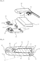
- Fig. 4 is a disassembled perspective view showing the configuration of a wing knob according to the present invention, wherein an upper knob 20 and a lower knob 30 are divided in the vertical direction and assembled with each other in a state, in which a vane 10, a rubber member 40 and a decoration member 50 are positioned between the upper knob 10 and the lower knob 30.
- Fig. 5 is a longitudinal sectional view showing the assembled state of each part.
- a plurality of vanes 10 for controlling the wind direction of the air vent is arranged at predetermined intervals and wing knobs are coupled thereto so as to control the direction of the vanes 10.
- the wing knob includes the upper knob 20 and the lower knob 30 which are assembled with each other as a single body, the rubber member 40 and the decoration member 50.
- the upper knob 20 and the lower knob 30 are formed in a shape, in which the upper knob 20 and the lower knob 30 are divided in the vertical direction and respectively provided at the upper and lower portions of the vane 10 so as to encompass the vane 10.
- the rubber member 40 is inserted into an internal portion defined by the upper knob 20 and the lower knob 30, which are made from synthetic resin materials, and is in contact with the end surface of the vane 10 in the insertion state, thereby improving the touch and reducing the friction noise when operating the wing knob.
- the decoration member 50 is provided between the upper knob 20 and the lower knob 30 in a state, in which the upper knob 20 and the lower knob 30 are assembled with each other as a single body, wherein the outside end portion of the decoration member 50 is exposed to the outside so as to provide decorative esthetic sense.
- the parts of the wing knob structured as above are possibly detached in the lengthwise direction of the vane 10, that is, towards the decoration member 50 when a shock or operation force is applied thereto in a state, in which the wing knob is mounted on the vane 10.
- the present invention is to prevent the generation of such a case in advance, wherein a coupling part is formed to be perpendicular to the lengthwise direction of the vane 10, that is, the detachment direction of the decoration member 50.
- the upper knob 20 has holding pieces 22 formed at the lower portion of an opening 21 which is open at one side.
- the holding pieces 22 are injection-molded at two positions spaced from each other as shown in Fig. 4 .
- the rubber member 40 has a shoulder portion 41 which is formed to be stepped in an approximate "L" shape as shown in Fig. 5 .
- the decoration member 50 has fitting grooves formed at two positions spaced from each other at a predetermined interval.
- the lower knob 30 is integrally formed with a hook 31 such that the hook 31 is held by the holding pieces 22 in a state, in which the lower knob 30 is moved forwards through the opening 21. Further, the lower knob 30 has a holding projection 32 formed to be folded upwards at an assembling position for the rubber member 40 so as to be held by the shoulder portion 41.
- the lower knob 30 is integrally formed with hook pieces 33 at positions corresponding to the fitting grooves 51 of the decoration member 50 such that the hook pieces 33 are fitted into the fitting grooves 51 and then held by the fitting grooves 51.
- the vane 10 the rubber member 40 and the decoration member 50 are positioned between the upper knob 20 and the lower knob 30 and then the hook 31 is moved forward through the opening 21 in a state, in which the lower knob 30 is slightly inclined in the direction of arrow "a" in Fig. 5 .
- the lower knob 30 is slightly pulled in the direction of arrow "b" in Fig. 5 (in the decoration member direction) and then slightly lifted and moved forwards.
- hook pieces 33 of the lower knob 30 are fitted into the fitting grooves 51 of the decoration member 50 so as to be held by the fitting grooves 51 of the decoration member 50.
- the holding projection 32 of the lower knob 30 can be held by the shoulder portion 41 of the rubber member 40 by the elastic force of the rubber member 40 which is made from a soft rubber material.
- the hook 31 and the hook pieces 33 are held at positions perpendicular to the detachment direction, that is, the exposure direction of the decoration member 50, such that the parts are prevented from being detached even if a shock or force is applied in the detachment direction.
- the vane 10 is provided with a groove portion 11 and the upper knob 20 is provided with a fitting protrusion 25 so as to be fitted into the groove portion 11 such that the vane 10 and the upper knob 20 are maintained in a perfect coupling state as being assembled with each other.
- the present invention is applied to the technique relating to the wing knob provided to an air vent.
- the present invention is applied to a technique for improving the quality of the wing knob so as to prevent the detachment of the wing knob while a user operates the same.
Landscapes
- Physics & Mathematics (AREA)
- Thermal Sciences (AREA)
- Engineering & Computer Science (AREA)
- Mechanical Engineering (AREA)
- Air-Conditioning For Vehicles (AREA)
- Air-Flow Control Members (AREA)
Claims (2)
- Struktur zum Befestigen eines Flügelgriffs für einen Fahrzeuglüfter, der eine Vielzahl von Lamellen (10) beinhaltet, die in einem vorbestimmten Abstand zum Steuern einer Ausströmrichtung des Lüfters angeordnet sind,
wobei die Struktur umfasst:einen oberen Griff (20) und einen unteren Griff (30), die dazu vorgesehen sind, eine der Lamellen (10) an ihren oberen und unteren Abschnitten umschließen, um einen Winkel der Lamelle (10) zu steuern,ein Gummielement (40), das zwischen dem oberen Griff (20) und dem unteren Griff (30) aufgenommen ist und die Lamelle (10) zum Reduzieren von Reibungsgeräuschen berührt, undein Dekorationselement (50), das zwischen dem oberen Griff (20) und dem unteren Griff (30) in einem Zustand gekoppelt ist, in dem der obere Griff (20) und der untere Griff (30) zu einem einzigen Körper zusammengefügt sind, um eine dekorativ-ästhetische Anmutung zu verleihen,dadurch gekennzeichnet, dassder obere Griff (20) Halteteile (22) aufweist, die an einem unteren Abschnitt einer Öffnung (21) ausgebildet sind, die an einer Seite des oberen Griffs (20) vorgesehen ist;das Gummielement (40) einen Schulterabschnitt (41) aufweist, der gestuft ausgebildet ist;das Dekorationselement (50) Passnuten (51) aufweist; undder untere Griff (30) integral mit Haken (31) versehen ist, die von den Halteteilen (22) in einem Zustand gehalten werden, in dem der untere Griff (30) durch die Öffnung (21) nach vorne bewegt wird, einem Haltevorsprung (32), der den Schulterabschnitt (41) des Gummielements (40) hält, und Hakenstücken (33), die in die Passnuten (51) des Dekorationselements (50) eingesetzt sind und darin gehalten werden. - Struktur zum Montieren eines Flügelgriffs für einen Fahrzeuglüfter nach Anspruch 1, wobei die Lamelle (10) mit einem Nutabschnitt (11) ausgebildet ist und der obere Griff (20) einen passenden Vorsprung (25) aufweist, der in den Nutabschnitt (11) der Lamelle (10) so einsetzbar ist, dass ein Kopplungszustand aufrechterhalten wird.
Applications Claiming Priority (2)
| Application Number | Priority Date | Filing Date | Title |
|---|---|---|---|
| KR20130151734 | 2013-12-06 | ||
| PCT/KR2014/011916 WO2015084100A1 (en) | 2013-12-06 | 2014-12-05 | Structure for mounting wing knob for vehicle air vent |
Publications (3)
| Publication Number | Publication Date |
|---|---|
| EP3077236A1 EP3077236A1 (de) | 2016-10-12 |
| EP3077236A4 EP3077236A4 (de) | 2017-08-16 |
| EP3077236B1 true EP3077236B1 (de) | 2019-01-16 |
Family
ID=53273774
Family Applications (1)
| Application Number | Title | Priority Date | Filing Date |
|---|---|---|---|
| EP14866948.4A Active EP3077236B1 (de) | 2013-12-06 | 2014-12-05 | Montagestruktur für zylinderknebel eines fahrzeugentlüfters |
Country Status (5)
| Country | Link |
|---|---|
| US (1) | US10266032B2 (de) |
| EP (1) | EP3077236B1 (de) |
| JP (1) | JP2016539840A (de) |
| CN (1) | CN105813868B (de) |
| WO (1) | WO2015084100A1 (de) |
Families Citing this family (14)
| Publication number | Priority date | Publication date | Assignee | Title |
|---|---|---|---|---|
| US10875387B1 (en) * | 2015-06-04 | 2020-12-29 | Leftcoast Diversified, Inc | Replacement vent clip for use with vehicle vent louvers |
| FR3043361B1 (fr) * | 2015-11-06 | 2018-07-13 | Reydel Automotive B.V. | Dispositif d'aerateur pour vehicule automobile |
| CN107639991B (zh) | 2016-07-20 | 2022-07-26 | 福特环球技术公司 | 出风口拨钮总成 |
| CN107781968B (zh) * | 2017-11-30 | 2023-09-01 | 芜湖美智空调设备有限公司 | 外壳及具有其的空调室内机 |
| US11460219B2 (en) * | 2019-11-29 | 2022-10-04 | Gd Midea Air-Conditioning Equipment Co., Ltd. | Deflector rod, air outlet frame assembly and air conditioner |
| CN114786976B (zh) * | 2019-12-11 | 2025-08-19 | 利富高(韩国)股份有限公司 | 汽车的薄型通风口 |
| KR102310012B1 (ko) * | 2019-12-11 | 2021-10-08 | 주식회사 니프코코리아 | 자동차의 에어벤트용 조절노브 |
| WO2021123776A1 (en) * | 2019-12-16 | 2021-06-24 | Bentley Motors Limited | Air vent |
| CN211918327U (zh) * | 2020-01-08 | 2020-11-13 | 王顺清 | 一种汽车空调吹风调节拨片活动卡扣结构 |
| KR102308675B1 (ko) * | 2020-02-05 | 2021-10-01 | 일리노이즈 툴 워크스 인코포레이티드 | 차량용 에어벤트 |
| KR102324047B1 (ko) * | 2020-02-05 | 2021-11-08 | 일리노이즈 툴 워크스 인코포레이티드 | 차량용 에어벤트 |
| DE102020112682A1 (de) * | 2020-05-11 | 2021-11-11 | Illinois Tool Works Inc. | Luftausströmer für fahrzeuge sowie verfahren zur herstellung eines solchen luftausströmers |
| KR102588817B1 (ko) * | 2021-07-12 | 2023-10-17 | 에코플라스틱 주식회사 | 에어벤트의 윙 노브 장치 |
| JP2023109515A (ja) | 2022-01-27 | 2023-08-08 | 日本プラスト株式会社 | 風向調整装置 |
Family Cites Families (20)
| Publication number | Priority date | Publication date | Assignee | Title |
|---|---|---|---|---|
| US5364303A (en) * | 1993-07-09 | 1994-11-15 | Summit Polymers, Inc. | Air vent adjustable vanes for controlling air flow direction |
| JP3406284B2 (ja) * | 2000-08-30 | 2003-05-12 | 森六株式会社 | 空調用吹出口装置 |
| US7162773B2 (en) * | 2003-11-10 | 2007-01-16 | Toyota Technical Center Usa, Inc. | Vent control knob for an automotive vehicle air vent |
| CA2474315A1 (en) * | 2004-07-15 | 2006-01-15 | Progressive Moulded Products Limited | Single piece vane knob |
| JP4327150B2 (ja) * | 2005-11-14 | 2009-09-09 | 豊和化成株式会社 | 空気吹出調整用レジスタ |
| JP4890203B2 (ja) * | 2006-11-20 | 2012-03-07 | 豊和化成株式会社 | 車室内用空気吹出装置 |
| KR100833164B1 (ko) * | 2006-12-13 | 2008-05-28 | 한국Trw자동차부품산업 주식회사 | 차량용 에어벤트 |
| JP4371326B2 (ja) * | 2007-10-16 | 2009-11-25 | 森六テクノロジー株式会社 | 空調用吹出口の送風方向変更装置 |
| JP2009113632A (ja) * | 2007-11-06 | 2009-05-28 | Howa Kasei Kk | レジスタ |
| JP2009115434A (ja) * | 2007-11-09 | 2009-05-28 | Howa Kasei Kk | レジスタ |
| KR200452765Y1 (ko) | 2008-11-03 | 2011-03-24 | 한국 티알더블류 자동차부품산업 주식회사 | 차량용 에어벤트 |
| JP2010115972A (ja) * | 2008-11-11 | 2010-05-27 | Howa Kasei Kk | レジスタ |
| DE202010000979U1 (de) * | 2010-01-15 | 2010-04-01 | Trw Automotive Electronics & Components Gmbh | Luftausströmer |
| WO2011161805A1 (ja) | 2010-06-25 | 2011-12-29 | 豊和化成株式会社 | ダンパプレート |
| DE102010047817A1 (de) * | 2010-10-07 | 2012-04-12 | Trw Automotive Electronics & Components Gmbh | Bedienelement für einen Luftausströmer |
| JP5814683B2 (ja) * | 2011-08-03 | 2015-11-17 | 豊和化成株式会社 | レジスタ用長尺状フィン |
| JP3176607U (ja) * | 2012-04-02 | 2012-06-28 | 豊和化成株式会社 | レジスタの操作ノブ装置 |
| JP6052080B2 (ja) * | 2013-07-03 | 2016-12-27 | トヨタ車体株式会社 | レジスタ |
| DE102013109934B3 (de) * | 2013-09-10 | 2014-11-20 | Trw Automotive Electronics & Components Gmbh | Bedienelement und Baugruppe für einen Luftausströmer sowie Verfahren zur Montage eines Bedienelements |
| KR20150068900A (ko) * | 2013-12-12 | 2015-06-22 | 가부시키가이샤 니프코 | 풍향조정장치 |
-
2014
- 2014-12-05 CN CN201480066427.XA patent/CN105813868B/zh active Active
- 2014-12-05 JP JP2016528861A patent/JP2016539840A/ja active Pending
- 2014-12-05 WO PCT/KR2014/011916 patent/WO2015084100A1/en not_active Ceased
- 2014-12-05 EP EP14866948.4A patent/EP3077236B1/de active Active
- 2014-12-05 US US15/102,090 patent/US10266032B2/en active Active
Non-Patent Citations (1)
| Title |
|---|
| None * |
Also Published As
| Publication number | Publication date |
|---|---|
| CN105813868A (zh) | 2016-07-27 |
| US10266032B2 (en) | 2019-04-23 |
| JP2016539840A (ja) | 2016-12-22 |
| US20160303942A1 (en) | 2016-10-20 |
| WO2015084100A1 (en) | 2015-06-11 |
| EP3077236A4 (de) | 2017-08-16 |
| EP3077236A1 (de) | 2016-10-12 |
| CN105813868B (zh) | 2018-01-09 |
Similar Documents
| Publication | Publication Date | Title |
|---|---|---|
| EP3077236B1 (de) | Montagestruktur für zylinderknebel eines fahrzeugentlüfters | |
| US8579141B2 (en) | Fitting structure for two members | |
| KR102310012B1 (ko) | 자동차의 에어벤트용 조절노브 | |
| CN107639991B (zh) | 出风口拨钮总成 | |
| KR20010093150A (ko) | 활꼴 핸들 및 상기 활꼴 핸들 내에 통합된 압력 작동부재를 갖는 자동차용 아웃 도어 핸들 | |
| US10107017B2 (en) | Inside door handle assembly for vehicle | |
| JP5821682B2 (ja) | 電装部品のガタツキ防止構造 | |
| CN106232401B (zh) | 空调格栅安装结构以及空调格栅安装方法 | |
| JP2007101029A (ja) | 空気調和機の室内ユニット | |
| JP5925499B2 (ja) | 車両用ドアの止水構造 | |
| CN204963378U (zh) | 冰箱的门端盖组件和具有其的冰箱 | |
| KR20130057122A (ko) | 에어벤트윙 조립체 | |
| CN204259303U (zh) | 家用电器操作面板的安装结构及其家用电器 | |
| CN105845470A (zh) | 用于电气开关的驱动器和具有这种驱动器的电气开关 | |
| WO2015020429A1 (en) | Vehicle air vent damper | |
| KR101246308B1 (ko) | 자동차의 스위치 노브 | |
| KR100551196B1 (ko) | 김치저장고의 전면디스플레이판넬 조립구조 | |
| CN203511513U (zh) | 用于汽车的装饰件安装结构及具有其的汽车 | |
| KR101481916B1 (ko) | 자동차용 에어벤트 다이얼 | |
| JP2013246914A (ja) | レバー式コネクタ | |
| CN201522665U (zh) | 旋钮 | |
| CN105972917A (zh) | 一种组合式冰箱门端盖、冰箱门及冰箱 | |
| CN204806274U (zh) | 电器工作状态指示灯结构及电器 | |
| CN104990342A (zh) | 冰箱的门端盖组件和具有其的冰箱 | |
| CN112478029B (zh) | 灯具模组 |
Legal Events
| Date | Code | Title | Description |
|---|---|---|---|
| PUAI | Public reference made under article 153(3) epc to a published international application that has entered the european phase |
Free format text: ORIGINAL CODE: 0009012 |
|
| 17P | Request for examination filed |
Effective date: 20160610 |
|
| AK | Designated contracting states |
Kind code of ref document: A1 Designated state(s): AL AT BE BG CH CY CZ DE DK EE ES FI FR GB GR HR HU IE IS IT LI LT LU LV MC MK MT NL NO PL PT RO RS SE SI SK SM TR |
|
| AX | Request for extension of the european patent |
Extension state: BA ME |
|
| DAX | Request for extension of the european patent (deleted) | ||
| A4 | Supplementary search report drawn up and despatched |
Effective date: 20170719 |
|
| RIC1 | Information provided on ipc code assigned before grant |
Ipc: B60H 1/34 20060101ALI20170713BHEP Ipc: B60H 1/00 20060101AFI20170713BHEP |
|
| GRAP | Despatch of communication of intention to grant a patent |
Free format text: ORIGINAL CODE: EPIDOSNIGR1 |
|
| STAA | Information on the status of an ep patent application or granted ep patent |
Free format text: STATUS: GRANT OF PATENT IS INTENDED |
|
| INTG | Intention to grant announced |
Effective date: 20180815 |
|
| GRAS | Grant fee paid |
Free format text: ORIGINAL CODE: EPIDOSNIGR3 |
|
| GRAA | (expected) grant |
Free format text: ORIGINAL CODE: 0009210 |
|
| STAA | Information on the status of an ep patent application or granted ep patent |
Free format text: STATUS: THE PATENT HAS BEEN GRANTED |
|
| AK | Designated contracting states |
Kind code of ref document: B1 Designated state(s): AL AT BE BG CH CY CZ DE DK EE ES FI FR GB GR HR HU IE IS IT LI LT LU LV MC MK MT NL NO PL PT RO RS SE SI SK SM TR |
|
| REG | Reference to a national code |
Ref country code: GB Ref legal event code: FG4D |
|
| REG | Reference to a national code |
Ref country code: CH Ref legal event code: EP |
|
| REG | Reference to a national code |
Ref country code: IE Ref legal event code: FG4D |
|
| REG | Reference to a national code |
Ref country code: DE Ref legal event code: R096 Ref document number: 602014040189 Country of ref document: DE |
|
| REG | Reference to a national code |
Ref country code: AT Ref legal event code: REF Ref document number: 1089452 Country of ref document: AT Kind code of ref document: T Effective date: 20190215 |
|
| REG | Reference to a national code |
Ref country code: NL Ref legal event code: MP Effective date: 20190116 |
|
| REG | Reference to a national code |
Ref country code: LT Ref legal event code: MG4D |
|
| PG25 | Lapsed in a contracting state [announced via postgrant information from national office to epo] |
Ref country code: NL Free format text: LAPSE BECAUSE OF FAILURE TO SUBMIT A TRANSLATION OF THE DESCRIPTION OR TO PAY THE FEE WITHIN THE PRESCRIBED TIME-LIMIT Effective date: 20190116 |
|
| REG | Reference to a national code |
Ref country code: AT Ref legal event code: MK05 Ref document number: 1089452 Country of ref document: AT Kind code of ref document: T Effective date: 20190116 |
|
| PG25 | Lapsed in a contracting state [announced via postgrant information from national office to epo] |
Ref country code: SE Free format text: LAPSE BECAUSE OF FAILURE TO SUBMIT A TRANSLATION OF THE DESCRIPTION OR TO PAY THE FEE WITHIN THE PRESCRIBED TIME-LIMIT Effective date: 20190116 Ref country code: PT Free format text: LAPSE BECAUSE OF FAILURE TO SUBMIT A TRANSLATION OF THE DESCRIPTION OR TO PAY THE FEE WITHIN THE PRESCRIBED TIME-LIMIT Effective date: 20190516 Ref country code: PL Free format text: LAPSE BECAUSE OF FAILURE TO SUBMIT A TRANSLATION OF THE DESCRIPTION OR TO PAY THE FEE WITHIN THE PRESCRIBED TIME-LIMIT Effective date: 20190116 Ref country code: ES Free format text: LAPSE BECAUSE OF FAILURE TO SUBMIT A TRANSLATION OF THE DESCRIPTION OR TO PAY THE FEE WITHIN THE PRESCRIBED TIME-LIMIT Effective date: 20190116 Ref country code: LT Free format text: LAPSE BECAUSE OF FAILURE TO SUBMIT A TRANSLATION OF THE DESCRIPTION OR TO PAY THE FEE WITHIN THE PRESCRIBED TIME-LIMIT Effective date: 20190116 Ref country code: NO Free format text: LAPSE BECAUSE OF FAILURE TO SUBMIT A TRANSLATION OF THE DESCRIPTION OR TO PAY THE FEE WITHIN THE PRESCRIBED TIME-LIMIT Effective date: 20190416 Ref country code: FI Free format text: LAPSE BECAUSE OF FAILURE TO SUBMIT A TRANSLATION OF THE DESCRIPTION OR TO PAY THE FEE WITHIN THE PRESCRIBED TIME-LIMIT Effective date: 20190116 |
|
| PG25 | Lapsed in a contracting state [announced via postgrant information from national office to epo] |
Ref country code: IS Free format text: LAPSE BECAUSE OF FAILURE TO SUBMIT A TRANSLATION OF THE DESCRIPTION OR TO PAY THE FEE WITHIN THE PRESCRIBED TIME-LIMIT Effective date: 20190516 Ref country code: GR Free format text: LAPSE BECAUSE OF FAILURE TO SUBMIT A TRANSLATION OF THE DESCRIPTION OR TO PAY THE FEE WITHIN THE PRESCRIBED TIME-LIMIT Effective date: 20190417 Ref country code: BG Free format text: LAPSE BECAUSE OF FAILURE TO SUBMIT A TRANSLATION OF THE DESCRIPTION OR TO PAY THE FEE WITHIN THE PRESCRIBED TIME-LIMIT Effective date: 20190416 Ref country code: RS Free format text: LAPSE BECAUSE OF FAILURE TO SUBMIT A TRANSLATION OF THE DESCRIPTION OR TO PAY THE FEE WITHIN THE PRESCRIBED TIME-LIMIT Effective date: 20190116 Ref country code: LV Free format text: LAPSE BECAUSE OF FAILURE TO SUBMIT A TRANSLATION OF THE DESCRIPTION OR TO PAY THE FEE WITHIN THE PRESCRIBED TIME-LIMIT Effective date: 20190116 Ref country code: HR Free format text: LAPSE BECAUSE OF FAILURE TO SUBMIT A TRANSLATION OF THE DESCRIPTION OR TO PAY THE FEE WITHIN THE PRESCRIBED TIME-LIMIT Effective date: 20190116 |
|
| REG | Reference to a national code |
Ref country code: DE Ref legal event code: R097 Ref document number: 602014040189 Country of ref document: DE |
|
| PG25 | Lapsed in a contracting state [announced via postgrant information from national office to epo] |
Ref country code: CZ Free format text: LAPSE BECAUSE OF FAILURE TO SUBMIT A TRANSLATION OF THE DESCRIPTION OR TO PAY THE FEE WITHIN THE PRESCRIBED TIME-LIMIT Effective date: 20190116 Ref country code: RO Free format text: LAPSE BECAUSE OF FAILURE TO SUBMIT A TRANSLATION OF THE DESCRIPTION OR TO PAY THE FEE WITHIN THE PRESCRIBED TIME-LIMIT Effective date: 20190116 Ref country code: SK Free format text: LAPSE BECAUSE OF FAILURE TO SUBMIT A TRANSLATION OF THE DESCRIPTION OR TO PAY THE FEE WITHIN THE PRESCRIBED TIME-LIMIT Effective date: 20190116 Ref country code: AL Free format text: LAPSE BECAUSE OF FAILURE TO SUBMIT A TRANSLATION OF THE DESCRIPTION OR TO PAY THE FEE WITHIN THE PRESCRIBED TIME-LIMIT Effective date: 20190116 Ref country code: DK Free format text: LAPSE BECAUSE OF FAILURE TO SUBMIT A TRANSLATION OF THE DESCRIPTION OR TO PAY THE FEE WITHIN THE PRESCRIBED TIME-LIMIT Effective date: 20190116 Ref country code: IT Free format text: LAPSE BECAUSE OF FAILURE TO SUBMIT A TRANSLATION OF THE DESCRIPTION OR TO PAY THE FEE WITHIN THE PRESCRIBED TIME-LIMIT Effective date: 20190116 Ref country code: AT Free format text: LAPSE BECAUSE OF FAILURE TO SUBMIT A TRANSLATION OF THE DESCRIPTION OR TO PAY THE FEE WITHIN THE PRESCRIBED TIME-LIMIT Effective date: 20190116 Ref country code: EE Free format text: LAPSE BECAUSE OF FAILURE TO SUBMIT A TRANSLATION OF THE DESCRIPTION OR TO PAY THE FEE WITHIN THE PRESCRIBED TIME-LIMIT Effective date: 20190116 |
|
| PLBE | No opposition filed within time limit |
Free format text: ORIGINAL CODE: 0009261 |
|
| STAA | Information on the status of an ep patent application or granted ep patent |
Free format text: STATUS: NO OPPOSITION FILED WITHIN TIME LIMIT |
|
| PG25 | Lapsed in a contracting state [announced via postgrant information from national office to epo] |
Ref country code: SM Free format text: LAPSE BECAUSE OF FAILURE TO SUBMIT A TRANSLATION OF THE DESCRIPTION OR TO PAY THE FEE WITHIN THE PRESCRIBED TIME-LIMIT Effective date: 20190116 |
|
| 26N | No opposition filed |
Effective date: 20191017 |
|
| PG25 | Lapsed in a contracting state [announced via postgrant information from national office to epo] |
Ref country code: SI Free format text: LAPSE BECAUSE OF FAILURE TO SUBMIT A TRANSLATION OF THE DESCRIPTION OR TO PAY THE FEE WITHIN THE PRESCRIBED TIME-LIMIT Effective date: 20190116 |
|
| PG25 | Lapsed in a contracting state [announced via postgrant information from national office to epo] |
Ref country code: TR Free format text: LAPSE BECAUSE OF FAILURE TO SUBMIT A TRANSLATION OF THE DESCRIPTION OR TO PAY THE FEE WITHIN THE PRESCRIBED TIME-LIMIT Effective date: 20190116 |
|
| REG | Reference to a national code |
Ref country code: CH Ref legal event code: PL |
|
| REG | Reference to a national code |
Ref country code: BE Ref legal event code: MM Effective date: 20191231 |
|
| PG25 | Lapsed in a contracting state [announced via postgrant information from national office to epo] |
Ref country code: MC Free format text: LAPSE BECAUSE OF FAILURE TO SUBMIT A TRANSLATION OF THE DESCRIPTION OR TO PAY THE FEE WITHIN THE PRESCRIBED TIME-LIMIT Effective date: 20190116 |
|
| GBPC | Gb: european patent ceased through non-payment of renewal fee |
Effective date: 20191205 |
|
| PG25 | Lapsed in a contracting state [announced via postgrant information from national office to epo] |
Ref country code: LU Free format text: LAPSE BECAUSE OF NON-PAYMENT OF DUE FEES Effective date: 20191205 Ref country code: IE Free format text: LAPSE BECAUSE OF NON-PAYMENT OF DUE FEES Effective date: 20191205 Ref country code: FR Free format text: LAPSE BECAUSE OF NON-PAYMENT OF DUE FEES Effective date: 20191231 Ref country code: GB Free format text: LAPSE BECAUSE OF NON-PAYMENT OF DUE FEES Effective date: 20191205 |
|
| PG25 | Lapsed in a contracting state [announced via postgrant information from national office to epo] |
Ref country code: BE Free format text: LAPSE BECAUSE OF NON-PAYMENT OF DUE FEES Effective date: 20191231 Ref country code: CH Free format text: LAPSE BECAUSE OF NON-PAYMENT OF DUE FEES Effective date: 20191231 Ref country code: LI Free format text: LAPSE BECAUSE OF NON-PAYMENT OF DUE FEES Effective date: 20191231 |
|
| PG25 | Lapsed in a contracting state [announced via postgrant information from national office to epo] |
Ref country code: CY Free format text: LAPSE BECAUSE OF FAILURE TO SUBMIT A TRANSLATION OF THE DESCRIPTION OR TO PAY THE FEE WITHIN THE PRESCRIBED TIME-LIMIT Effective date: 20190116 |
|
| PG25 | Lapsed in a contracting state [announced via postgrant information from national office to epo] |
Ref country code: MT Free format text: LAPSE BECAUSE OF FAILURE TO SUBMIT A TRANSLATION OF THE DESCRIPTION OR TO PAY THE FEE WITHIN THE PRESCRIBED TIME-LIMIT Effective date: 20190116 Ref country code: HU Free format text: LAPSE BECAUSE OF FAILURE TO SUBMIT A TRANSLATION OF THE DESCRIPTION OR TO PAY THE FEE WITHIN THE PRESCRIBED TIME-LIMIT; INVALID AB INITIO Effective date: 20141205 |
|
| PG25 | Lapsed in a contracting state [announced via postgrant information from national office to epo] |
Ref country code: MK Free format text: LAPSE BECAUSE OF FAILURE TO SUBMIT A TRANSLATION OF THE DESCRIPTION OR TO PAY THE FEE WITHIN THE PRESCRIBED TIME-LIMIT Effective date: 20190116 |
|
| PGFP | Annual fee paid to national office [announced via postgrant information from national office to epo] |
Ref country code: DE Payment date: 20251028 Year of fee payment: 12 |