EP3077249B1 - Vorschwenkmechanismus für einen fahrzeugsitz und fahrzeugsitz - Google Patents
Vorschwenkmechanismus für einen fahrzeugsitz und fahrzeugsitz Download PDFInfo
- Publication number
- EP3077249B1 EP3077249B1 EP14809331.3A EP14809331A EP3077249B1 EP 3077249 B1 EP3077249 B1 EP 3077249B1 EP 14809331 A EP14809331 A EP 14809331A EP 3077249 B1 EP3077249 B1 EP 3077249B1
- Authority
- EP
- European Patent Office
- Prior art keywords
- seat
- backrest
- easy
- vehicle seat
- entry
- Prior art date
- Legal status (The legal status is an assumption and is not a legal conclusion. Google has not performed a legal analysis and makes no representation as to the accuracy of the status listed.)
- Active
Links
Images





Classifications
-
- B—PERFORMING OPERATIONS; TRANSPORTING
- B60—VEHICLES IN GENERAL
- B60N—SEATS SPECIALLY ADAPTED FOR VEHICLES; VEHICLE PASSENGER ACCOMMODATION NOT OTHERWISE PROVIDED FOR
- B60N2/00—Seats specially adapted for vehicles; Arrangement or mounting of seats in vehicles
- B60N2/02—Seats specially adapted for vehicles; Arrangement or mounting of seats in vehicles the seat or part thereof being movable, e.g. adjustable
- B60N2/20—Seats specially adapted for vehicles; Arrangement or mounting of seats in vehicles the seat or part thereof being movable, e.g. adjustable the back-rest being tiltable, e.g. to permit easy access
-
- B—PERFORMING OPERATIONS; TRANSPORTING
- B60—VEHICLES IN GENERAL
- B60N—SEATS SPECIALLY ADAPTED FOR VEHICLES; VEHICLE PASSENGER ACCOMMODATION NOT OTHERWISE PROVIDED FOR
- B60N2/00—Seats specially adapted for vehicles; Arrangement or mounting of seats in vehicles
- B60N2/02—Seats specially adapted for vehicles; Arrangement or mounting of seats in vehicles the seat or part thereof being movable, e.g. adjustable
- B60N2/04—Seats specially adapted for vehicles; Arrangement or mounting of seats in vehicles the seat or part thereof being movable, e.g. adjustable the whole seat being movable
- B60N2/12—Seats specially adapted for vehicles; Arrangement or mounting of seats in vehicles the seat or part thereof being movable, e.g. adjustable the whole seat being movable slidable and tiltable
-
- B—PERFORMING OPERATIONS; TRANSPORTING
- B60—VEHICLES IN GENERAL
- B60N—SEATS SPECIALLY ADAPTED FOR VEHICLES; VEHICLE PASSENGER ACCOMMODATION NOT OTHERWISE PROVIDED FOR
- B60N2/00—Seats specially adapted for vehicles; Arrangement or mounting of seats in vehicles
- B60N2/02—Seats specially adapted for vehicles; Arrangement or mounting of seats in vehicles the seat or part thereof being movable, e.g. adjustable
- B60N2/20—Seats specially adapted for vehicles; Arrangement or mounting of seats in vehicles the seat or part thereof being movable, e.g. adjustable the back-rest being tiltable, e.g. to permit easy access
- B60N2/206—Seats specially adapted for vehicles; Arrangement or mounting of seats in vehicles the seat or part thereof being movable, e.g. adjustable the back-rest being tiltable, e.g. to permit easy access to a position in which it can be used as a support for objects, e.g. as a tray
-
- B—PERFORMING OPERATIONS; TRANSPORTING
- B60—VEHICLES IN GENERAL
- B60N—SEATS SPECIALLY ADAPTED FOR VEHICLES; VEHICLE PASSENGER ACCOMMODATION NOT OTHERWISE PROVIDED FOR
- B60N2/00—Seats specially adapted for vehicles; Arrangement or mounting of seats in vehicles
- B60N2/02—Seats specially adapted for vehicles; Arrangement or mounting of seats in vehicles the seat or part thereof being movable, e.g. adjustable
- B60N2/22—Seats specially adapted for vehicles; Arrangement or mounting of seats in vehicles the seat or part thereof being movable, e.g. adjustable the back-rest being adjustable
- B60N2/2227—Seats specially adapted for vehicles; Arrangement or mounting of seats in vehicles the seat or part thereof being movable, e.g. adjustable the back-rest being adjustable and provided with braking systems
-
- B—PERFORMING OPERATIONS; TRANSPORTING
- B60—VEHICLES IN GENERAL
- B60N—SEATS SPECIALLY ADAPTED FOR VEHICLES; VEHICLE PASSENGER ACCOMMODATION NOT OTHERWISE PROVIDED FOR
- B60N2/00—Seats specially adapted for vehicles; Arrangement or mounting of seats in vehicles
- B60N2/02—Seats specially adapted for vehicles; Arrangement or mounting of seats in vehicles the seat or part thereof being movable, e.g. adjustable
- B60N2/22—Seats specially adapted for vehicles; Arrangement or mounting of seats in vehicles the seat or part thereof being movable, e.g. adjustable the back-rest being adjustable
- B60N2/235—Seats specially adapted for vehicles; Arrangement or mounting of seats in vehicles the seat or part thereof being movable, e.g. adjustable the back-rest being adjustable by gear-pawl type mechanisms
- B60N2/2352—Seats specially adapted for vehicles; Arrangement or mounting of seats in vehicles the seat or part thereof being movable, e.g. adjustable the back-rest being adjustable by gear-pawl type mechanisms with external pawls
-
- B—PERFORMING OPERATIONS; TRANSPORTING
- B60—VEHICLES IN GENERAL
- B60N—SEATS SPECIALLY ADAPTED FOR VEHICLES; VEHICLE PASSENGER ACCOMMODATION NOT OTHERWISE PROVIDED FOR
- B60N2/00—Seats specially adapted for vehicles; Arrangement or mounting of seats in vehicles
- B60N2/02—Seats specially adapted for vehicles; Arrangement or mounting of seats in vehicles the seat or part thereof being movable, e.g. adjustable
- B60N2/22—Seats specially adapted for vehicles; Arrangement or mounting of seats in vehicles the seat or part thereof being movable, e.g. adjustable the back-rest being adjustable
- B60N2/235—Seats specially adapted for vehicles; Arrangement or mounting of seats in vehicles the seat or part thereof being movable, e.g. adjustable the back-rest being adjustable by gear-pawl type mechanisms
- B60N2/2356—Seats specially adapted for vehicles; Arrangement or mounting of seats in vehicles the seat or part thereof being movable, e.g. adjustable the back-rest being adjustable by gear-pawl type mechanisms with internal pawls
-
- B—PERFORMING OPERATIONS; TRANSPORTING
- B60—VEHICLES IN GENERAL
- B60N—SEATS SPECIALLY ADAPTED FOR VEHICLES; VEHICLE PASSENGER ACCOMMODATION NOT OTHERWISE PROVIDED FOR
- B60N2/00—Seats specially adapted for vehicles; Arrangement or mounting of seats in vehicles
- B60N2/90—Details or parts not otherwise provided for
- B60N2/919—Positioning and locking mechanisms
- B60N2/933—Positioning and locking mechanisms rotatable
- B60N2/938—Positioning and locking mechanisms rotatable and provided with braking systems
-
- B—PERFORMING OPERATIONS; TRANSPORTING
- B60—VEHICLES IN GENERAL
- B60N—SEATS SPECIALLY ADAPTED FOR VEHICLES; VEHICLE PASSENGER ACCOMMODATION NOT OTHERWISE PROVIDED FOR
- B60N2/00—Seats specially adapted for vehicles; Arrangement or mounting of seats in vehicles
- B60N2/90—Details or parts not otherwise provided for
- B60N2/919—Positioning and locking mechanisms
- B60N2002/952—Positioning and locking mechanisms characterised by details of the locking system
Definitions
- the invention relates to a forward pivot mechanism, in particular an easy-entry system, for a vehicle seat and a vehicle seat with such a forward pivot mechanism, in particular with an easy-entry system.
- the easy-entry system can be actuated by an unlocking lever, which is usually arranged on a seat back upper edge of the vehicle seat, whereby the seat back of the vehicle seat pivots out of an entry area. If the vehicle seat is arranged on rails, the vehicle seat can additionally or alternatively be displaceable in the direction of travel when the unlocking lever is actuated. Furthermore, the vehicle seat has a comfort adjustment of the seat back and a loading floor function. These two functions can be operated using a comfort lever.
- a motor vehicle seat with an easy-entry system in which a stop bolt fixed to the backrest runs into a mouth of a pawl and thus forms a stop for folding the backrest forward.
- the EP 1 302 361 A1 , WO 2005/108152 A2 and DE 10 2011 012 562 A12 A1 disclose further motor vehicle seats with an easy entry system.
- the object of the present invention is to provide an improved forward pivoting mechanism, in particular a simplified easy entry system, for a vehicle seat and a vehicle seat with such an improved forward pivot mechanism, in particular an easy entry system.
- the forward pivot mechanism for positioning a seat back of a vehicle seat in at least one front position, in particular in an easy-entry position, and for positioning the seat back beyond the front position in at least one further front position, in particular a loading floor position, comprises a comfort lock for positioning and locking of the seat back in at least one seat position, and an easy-entry latch for positioning the seat back in the at least one front position, wherein a pivoting range of the seat back in the at least one front position can be limited by means of the easy-entry latch, wherein the easy-entry pawl is designed such that it forms a stop to the front when the seat back is adjusted from one of the seat positions into one of the front positions.
- the easy-entry pawl can be switched and brought into a position in which a pawl or a pawl of the easy-entry pawl engages with an end stop.
- a possible embodiment of the invention provides that on the seat back side, corresponding to the stop of the easy-entry pawl, the End stop is provided, which interacts in a self-locking manner with the stop, in particular with the locking hook or the locking pawl, the easy-entry pawl in the front position of the seat back.
- the easy-entry pawl is pivotable and spring-loaded on a lower fitting part.
- a spring element arranged in the area of the axis of rotation of the easy-entry pawl in particular a spiral spring, for example a spiral spring, the easy-entry pawl can be brought into a position after unlocking the seat back from one of the seating positions and when pivoting the seat back forwards, in particular pivotable, in which the locking hook or the locking pawl acts as a stop to limit further pivoting of the seat back forwards.
- the end stop engages a soft lock in such a way that a soft locking force is greater than a longitudinal / rail adjustment force of the vehicle seat is. This ensures that the vehicle seat can first be moved into a rearward or rearmost position by means of a longitudinal adjustment, in particular, can be driven before the seat back is pivoted into the seating position in the comfort area.
- the soft lock is designed as an L-profile which has at least one outer contour with at least one control or switching cam, in particular in the form of a projection, which interacts with the end stop.
- the soft lock is pivotable and spring-loaded, in particular resiliently preloaded, articulated on the lower fitting part.
- the switch cam and a spring force in particular a soft lock spring, for example in the form of a return spring, must be overcome, whereby the soft lock force is defined or determined.
- the switching cam can have such different slopes that the soft locking forces acting when pivoting the seat back forwards or backwards are different.
- the rises of the switching cam in the pivoting direction forwards and backwards can be designed to be the same, so that the same soft locking force must be overcome in both pivoting directions of the seat back.
- the soft lock spring / return spring is hinged in particular at one end to the soft lock and at the other end to the lower part of the fitting.
- the soft lock can be designed to be lengthened in such a way that in one of the front positions of the seat back it is held by a self-locking interaction of the end stop and the soft lock.
- the extended soft lock has a locking cam, in particular a locking projection, in the outer contour in the area of the extension.
- the locking cam can be arranged on an inner contour of the soft lock.
- a vehicle seat according to the invention with a tilt-adjustable and freely pivotable seat back and a longitudinal adjuster has the previously described pre-pivoting mechanism for adjusting the inclination and free pivoting of the seat back by means of a switchable easy-entry latch and with an integrated soft lock function by means of a soft lock.
- the longitudinal adjuster and the forward pivoting mechanism work together in such a way that, when the seat backrest is pivoted forward, the vehicle seat is in one of the front positions before the seat backrest pivots back a sitting position can only be moved backwards in that the soft locking force is greater than a longitudinal adjustment force.
- the object is also achieved according to the invention with a fitting that is equipped with a forward pivoting mechanism, in particular an easy-entry system and / or a loading system, for positioning a seat back of a vehicle seat in at least one front position, in particular in an easy-entry position and / or a loading position, with a comfort lock for positioning the seat back in at least one seat position and an extended comfort function for positioning the seat back beyond the front position, in particular the easy-entry position and / or a loading position, into a loading floor position, with a
- the pivoting range of the seat back in the front position, in particular in the easy-entry position and / or loading position is limited by means of an easy-entry pawl engaging in the at least one fitting part, the easy-entry pawl being designed in such a way that this when adjusting the seat back from the comfort area into a front ere position, in particular into the easy-entry position and / or the loading position, is pivoted in such a way that the easy-entry
- the invention enables the vehicle seat to move from a front longitudinal position to a rear or rearmost longitudinal position before the seat back of the vehicle seat is placed or swiveled from the front position, such as the easy-entry position or the loading position, into one of the seating positions in the comfort area .
- This increases the security of the user because a suitable, in particular lockable, driving or longitudinal position of the vehicle seat is approached.
- the easy-entry latch which is set up as a stop in the front position of the seat back, also ensures that the seat back is prevented from pivoting further forward.
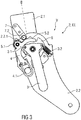
- the Figure 1 shows a schematic side view of part of a vehicle seat 1 with a seat back 1.1 and a seat cushion 1.2 in the area of a fitting 2, the seat back 1.1 being rotatably arranged on the seat cushion 1.2 by means of the fitting 2.
- the fitting 2 has a forward pivoting mechanism V, which is set up according to the invention to have at least one function, namely the function of an entry aid (easy-entry system).
- the fitting 2 comprises an easy-entry latch 5 as an entry aid.
- the forward pivoting mechanism serves as a loading aid, the fitting 2 has a locking lever.
- the two functions differ only in the angle of inclination when the seat back 1.1 is pivoted forward.
- the easy-entry pawl 5 or the locking lever are designed to correspond with inner or outer guide, locking and / or control contours for the respective integrated functions.
- the invention is described below for a forward pivoting mechanism V designed in particular as an easy-entry system EE with an easy-entry position D as the front position.
- the invention can be applied analogously to a pre-pivoting mechanism V designed as a loading system, not shown in detail, with a correspondingly designed and configured locking lever being provided instead of the easy-entry pawl 5.
- the vehicle seat 1 is, for example, a front seat or a vehicle seat in a rear, for example a second row of seats for a vehicle and is arranged on a rail system, whereby the vehicle seat 1 can be displaced in the longitudinal direction LR of the vehicle by means of a longitudinal adjuster, not shown.
- the vehicle seat 1 has an easy-entry function that can be implemented by means of an easy-entry system EE of the fitting 2.
- the easy entry function is an entry aid that enables enlarged and therefore more convenient access to the rear area, in particular of a two-door vehicle or to a rear row of seats in a multi-door vehicle.
- the vehicle seat 1 is moved on the rail system in the longitudinal direction LR, in particular forwards in the direction of travel, in order to enlarge the entry area, while at the same time the seat back 1.1 of the vehicle seat 1 moves forward into an easy-entry position D. is folded.
- the seat back 1.1 can be pivoted into a further comfort position, in particular into a loading position E and / or a loading floor position L, by means of an extended comfort function.
- the seat back 1.1 can be pivoted about a pivot axis which extends in the direction of the transverse extent of the vehicle.
- the pivoting of the seat back 1.1 can be triggered by actuating an actuating lever, not shown, which is articulated to a release lever 3 of the easy-entry system EE, spring-loaded with a return spring 3.2, at an articulation point 3.1 via a Bowden cable (not shown) or another suitable tension element.
- the actuation lever is only provided on one side of the vehicle seat 1.
- a fitting 2 is arranged on each side of the vehicle seat 1 and is formed from an upper fitting part 2.1 and a lower fitting part 2.2. Alternatively, only one fitting 2 can be provided, with a pivot bearing for a transmission rod being provided on the opposite side of the vehicle seat 1.
- the upper fitting part 2.1 is fixed to the backrest 1.1 and the lower fitting part 2.2 is arranged fixed to the substructure, for example on the vehicle floor or on the seat cushion 1.2.
- the fitting 2 in particular a rotary and / or latching fitting, is designed as a gear connection in such a way that a rotational movement occurs relative between the upper fitting part 2.1 and the lower fitting part 2.2.
- the fittings 2 arranged on each side of the seat back 1.1 are coupled to one another via a transmission element (not shown) in the form of a cranked transmission rod or a tube, so that the seat back 1.1 can be locked on both sides so that it can be pivoted.
- a transmission element (not shown) in the form of a cranked transmission rod or a tube, so that the seat back 1.1 can be locked on both sides so that it can be pivoted.
- a fitting 2 at one end of the Transmission element attached positively.
- a fitting 2 can be arranged on only one side of the vehicle seat 1 and a pivot bearing for receiving the transmission element is provided on the opposite side of the vehicle seat 1.
- the transmission element is, in particular, a rod or a tube which connects the fitting component to a possibly further fitting component, the transmission element being rotatable about its longitudinal axis, as shown in FIG DE 10 2004 008 599 B3 is known.
- the forward pivot mechanism V includes the easy-entry system EE and the extended convenience function for the loading position E and / or the loading floor position L, which is integrated in the fitting 2 and in Figure 1 are shown in more detail.
- the easy-entry system EE comprises a rotatably arranged on the fitting 2 and with an associated return spring 4.1 spring-loaded soft lock 4 and the release lever 3, which is also rotatably arranged on the fitting 2, as well as the easy-entry latch 5.
- this includes Easy-Entry-System EE an end stop 7 on the backrest side.
- the soft lock 4 and the unlocking lever 3 can be rotated about a separate pivot and pivot axis and the soft lock 4 and the easy-entry pawl 5 can be rotated about a common pivot and pivot axis.
- the soft lock 4 is designed in the manner of a lever or an L-profile.
- the release lever 3 is operated to trigger an adjustment function in the comfort area in the seat positions A to C, whereby the seat back 1.1 can be pivoted from a seat position A via seat positions B and C (also called comfort, use or backrest positions) or vice versa.
- the adjustment and positioning of the seat back 1.1 to the rear and thus into the seat position A is limited by the end stop 7 on the backrest side, in particular fixed to the backrest, which abuts a stop 2.2.1 of the lower fitting part 2.2.
- the end stop 7 on the backrest and fixed to the backrest comprises a receptacle 7.1 for a rolling element 7.2.
- the rolling element 7.2 of the end stop 7 and the soft lock 4 are decoupled from one another and have no contact.
- the rails of the rail system of the vehicle seat 1 and the fitting 2 are closed.
- the easy-entry pawl 5 is located with a designed as an outer contour 5.2 stop contour on the end stop 7 of the upper fitting part 2.1, in particular on the rolling element 7.2.
- the rolling element 7.2 of the end stop 7 fixed to the backrest is formed as a stop surface protruding from the surface of the upper fitting part 2.1, in particular as a stop roller or a stop pin / pin.
- the end stop 7 can be designed separately as a profile element, in particular as an L-profile, and fastened, in particular welded, to the upper fitting part 2.1.
- Figures 2 and 3 show the seat back 1.1 in the seat position B of a medium comfort position or normal position in the comfort range.
- the rail and the fitting 2 are closed.
- the soft lock 4 and the end stop 7 are decoupled.
- the rolling element 7.2 rests against the outer contour 5.2 of the easy-entry pawl 5.
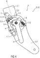
- Figure 4 shows the seat back 1.1 in the rear seat position A of a rear comfort position in the comfort area.
- the rail and the fitting 2 are closed.
- the soft lock 4 and the end stop 7 are decoupled.
- the end stop 7 strikes a bottom or seat part-side / -fixed stop 2.2.1 of the fitting lower part 2.2 and thus limits the adjustment of the seat back 1.1 to the rear.
- Figure 5 shows the seat back 1.1 in the front seat position C, a front comfort position in the comfort area.
- the rail and the fitting 2 are closed.
- the soft lock 4 and the end stop 7 are at least partially decoupled, in particular decoupled until the rolling element 7.2 protruding from the end stop 7 strikes a control contour 4.2 (also called switching contour), in particular a projection protruding from the outer contour, the soft lock 4.
- Figures 6 and 7th show the positions and the movement of the end stop 7 relative to the soft lock 4 and the control contour 4.2 from the front seat position C to the starting position C1 for a free pivoting movement of the seat back 1.1 out of the comfort area into the easy-entry position D or the loading position E or the Loading floor position L.
- the control contour 4.2 is designed as a profiled outer contour along which the rolling element 7.2 is guided.
- the rolling element 7.2 can be guided in the manner of a pin in an inner contour of the soft lock 4.
- the spring force of the return spring 4.1 (also called soft lock spring) of the pre-tensioned soft lock 4 (also called soft lock) must be overcome.
- the release lever 3 is actuated and the seat back 1.1 is pivoted out of the comfort area from the front seat position C forwards in the direction of the starting position C1, the fitting 2 being opened.
- the rail (not shown) is unlocked via a Bowden cable (not shown) so that the vehicle seat 1 can be moved further forward.
- a spring element 5.1 hinged to the easy-entry pawl 5 and / or the soft lock 4 rotates the easy-entry pawl 5 upwards along the arrows P1 and serves as a forward stop ( self-locking effect), as shown in FIG Figures 8 to 10 is shown.
- the easy-entry pawl 5 comprises a locking pawl 5.3.
- the easy entry position D has been reached.
- the soft lock force (also called soft lock force) is greater than the rail adjustment force. This ensures that the vehicle seat 1 first moves back along the rail into a rearmost / rearmost position before the seat back 1.1 is placed in the front seat position C or reaches it. This serves to protect the user, since a suitable driving or longitudinal position of the vehicle seat 1 in the rail (locked) is ensured.
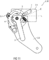
- the release lever 3 In order to reach the loading position E or the loading floor position L (also called the folding position), the release lever 3 must be actuated again. This lowers the easy-entry pawl 5, as a result of which the seat back 1.1 can be folded further forward, as shown in FIG Figure 11 is shown.
- the lower fitting part 2.2 in particular a projection, now serves as a stop again.
- a locking function can be used in the fitting 2, whereby higher forces are possible.
- the release lever 3 can either be actuated or not (either with or without the latching function).
- the soft lock 4 can be modified, in particular extended, in order to achieve a holding function in the loading floor position L (same principle as the easy-entry position), as in FIG Figure 12 shown.
- the soft lock 4 has a locking cam 4.3 in the outer contour in the area of the extension, whereby the end stop 7 and the soft lock 4 interact in a self-locking manner.
- the locking cam 4.3 can also be formed on the inner contour of the soft lock 4.
- the easy entry position D makes it easier to get into a row of seats behind it.
- the seat back 1.1 is pivoted from one of the seat positions A to C into a front position, the easy entry position D (for example approx. 35 ° forward) and at the same time the longitudinal adjustment rails are opened, whereby the vehicle seat 1 moves forward to allow a maximum boarding area.
- the loading volume of the motor vehicle is maximized.
- the seat back 1.1 is folded or swiveled forward into the loading floor position L in order to create a flat loading area.
- the free swing position or movement is understood in particular to mean the state of the seat back 1.1 in which the fitting 2 is open and the seat back 1.1 can be pivoted without actuating the release lever 3.
Landscapes
- Engineering & Computer Science (AREA)
- Aviation & Aerospace Engineering (AREA)
- Transportation (AREA)
- Mechanical Engineering (AREA)
- Seats For Vehicles (AREA)
Description
- Die Erfindung betrifft ein Vorschwenkmechanismus, insbesondere ein Easy-Entry-System, für einen Fahrzeugsitz und einen Fahrzeugsitz mit einem solchen Vorschwenkmechanismus, insbesondere mit einem Easy-Entry-System.
- Im Stand der Technik sind verschiedene Easy-Entry-Systeme bekannt, die Bestandteil eines Fahrzeugsitzes sind, welche einen erleichterten Einstieg in eine zweite Sitzreihe eines Fahrzeuges ermöglichen. Das Easy-Entry-System ist durch einen Entriegelungshebel, welcher üblicherweise an einer Sitzlehnen-Oberkante des Fahrzeugsitzes angeordnet ist, betätigbar, wodurch die Sitzlehne des Fahrzeugsitzes aus einem Einstiegsbereich schwenkt. Ist der Fahrzeugsitz auf Schienen angeordnet, kann der Fahrzeugsitz bei Betätigung des Entriegelungshebels zusätzlich oder alternativ in Fahrtrichtung verschiebbar sein. Des Weiteren weist der Fahrzeugsitz eine Komfortverstellung der Sitzlehne und eine Ladebodenfunktion auf. Diese beiden Funktionen sind mittels eines Komforthebels betätigbar.
- Aus der
DE 10 2004 015 450 A1 ist ein Kraftfahrzeugsitz mit einem Easy-Entry-System bekannt, bei dem ein lehnenfester Anschlagbolzen in ein Maul einer Klinke einläuft und so einen Anschlag für das Vorklappen der Rückenlehne bildet. - Die
EP 1 302 361 A1 ,WO 2005/108152 A2 undDE 10 2011 012 562 A12 A1 - Aufgabe der vorliegenden Erfindung ist es, einen gegenüber dem Stand der Technik verbesserten Vorschwenkmechanismus, insbesondere ein vereinfachtes Easy-Entry-System, für einen Fahrzeugsitz und einen Fahrzeugsitz mit einem solchen verbesserten Vorschwenkmechanismus, insbesondere einem Easy-Entry-System, anzugeben.
- Die Aufgabe wird hinsichtlich des Vorschwenkmechanismus durch die Merkmale des Anspruchs 1 gelöst. Hinsichtlich des Fahrzeugsitzes wird die Erfindung durch die im Anspruch 9 angegebenen Merkmale gelöst.
- Der erfindungsgemäße Vorschwenkmechanismus zur Positionierung einer Sitzlehne eines Fahrzeugsitzes in mindestens eine vordere Position, insbesondere in eine Easy-Entry-Position, und zur Positionierung der Sitzlehne über die vordere Position hinaus in zumindest eine weitere vordere Position, insbesondere eine Ladebodenposition, umfasst eine Komfortverriegelung zur Positionierung und Verriegelung der Sitzlehne in mindestens eine/r Sitzposition, und eine Easy-Entry-Klinke zum Positionieren der Sitzlehne in die mindestens eine vordere Position, wobei ein Schwenkbereich der Sitzlehne in die mindestens eine vordere Position mittels der Easy-Entry-Klinke begrenzbar ist, wobei die Easy-Entry-Klinke derart ausgebildet ist, dass diese beim Verstellen der Sitzlehne aus einer der Sitzpositionen hinaus in eine der vorderen Positionen einen Anschlag nach vorne bildet.
- Zur Erzielung der Begrenzung des Schwenkbereichs der Sitzlehne ist die Easy-Entry-Klinke schaltbar und in eine Stellung bringbar, in welcher ein Sperrhaken oder eine Sperrklinke der Easy-Entry-Klinke in Eingriff mit einem Endanschlag kommt.
- Eine mögliche Ausführungsform der Erfindung sieht vor, dass sitzlehnenseitig, korrespondierend zum Anschlag der Easy-Entry-Klinke, der Endanschlag vorgesehen ist, der mit dem Anschlag, insbesondere mit dem Sperrhaken oder der Sperrklinke, der Easy-Entry-Klinke in der vorderen Position der Sitzlehne selbsthemmend zusammenwirkt.
- Gemäß einer Weiterbildung ist die Easy-Entry-Klinke schwenkbar und federbelastet an einem Beschlagunterteil angelenkt. Durch ein im Bereich der Drehachse der Easy-Entry-Klinke angeordnetes Federelement, insbesondere eine Biegefeder, beispielsweise eine Spiralfeder, ist nach Entriegelung der Sitzlehne aus einer der Sitzpositionen und beim Schwenken der Sitzlehne nach vorne die Easy-Entry-Klinke in eine Stellung bringbar, insbesondere schwenkbar, in welcher der Sperrhaken oder die Sperrklinke als Anschlag wirkt zur Begrenzung eines weiteren Schwenkens der Sitzlehne nach vorne.
- Beim Wiederaufrichten der Sitzlehne aus der vorderen Position, insbesondere eine Easy-Entry-Position oder Ladebodenposition, hinaus in eine der Sitzpositionen im Komfortbereich hinein, steht der Endanschlag derart in Eingriff mit einer Softsperre, dass eine Softsperrkraft größer als eine Längs-/Schienenverstellkraft des Fahrzeugsitzes ist. Hierdurch ist sichergestellt, dass der Fahrzeugsitz zunächst mittels einer Längsverstellung in eine hintere oder hinterste Position gestellt, insbesondere gefahren werden kann, bevor die Sitzlehne in die Sitzposition im Komfortbereich geschwenkt wird.
- In einer möglichen Ausführungsform ist die Softsperre als ein L-Profil ausgebildet, das zumindest eine Außenkontur mit zumindest einer Steuer- oder Schaltnocke, insbesondere in Form eines Vorsprungs, aufweist, welche mit dem Endanschlag zusammenwirkt. Gemäß einer Ausführungsform ist die Softsperre schwenkbar und federbelastet, insbesondere federnd vorgespannt, am Beschlagunterteil angelenkt.
- Beim Gleiten des Endanschlags, insbesondere eines am Endanschlag angeordneten Rollelements, an der Außenkontur der Softsperre ist die Schaltnocke und eine Federkraft, insbesondere einer Softsperrfeder beispielsweise in Form einer Rückstellfeder, zu überwinden, wodurch die Softsperrkraft definiert oder bestimmt ist. Dabei kann die Schaltnocke derart unterschiedliche Anstiege aufweisen, dass die beim Schwenken der Sitzlehne nach vorne oder nach hinten wirkenden Softsperrkräfte verschieden sind. Alternativ können die Anstiege der Schaltnocke in Schwenkrichtung nach vorne und nach hinten gleich ausgebildet sein, so dass in beiden Schwenkrichtungen der Sitzlehne dieselbe Softsperrkraft überwunden werden muss. Die Softsperrfeder/Rückstellfeder ist insbesondere mit einem Ende an der Softsperre und mit dem anderen Ende am Beschlagunterteil angelenkt.
- In einer alternativen Ausführungsform kann die Softsperre derart verlängert ausgebildet sein, dass in einer der vorderen Positionen der Sitzlehne diese durch ein selbsthemmendes Zusammenwirken von Endanschlag und Softsperre gehalten wird. Insbesondere weist die verlängerte Softsperre im Bereich der Verlängerung eine Sperrnocke, insbesondere einen sperrenden Vorsprung, in der Außenkontur auf. Alternativ kann die Sperrnocke an einer Innenkontur der Softsperre angeordnet sein.
- Ein erfindungsgemäßer Fahrzeugsitz mit einer neigungseinstellbaren und frei schwenkbaren Sitzlehne und einem Längseinsteller weist den zuvor beschriebenen Vorschwenkmechanismus zur Neigungseinstellung und zum Freischwenken der Sitzlehne mittels einer schaltbaren Easy-Entry-Klinke und mit einer integrierten Softsperrfunktion mittels einer Softsperre auf. Dabei wirken der Längseinsteller und der Vorschwenkmechanismus derart zusammen, dass der Fahrzeugsitz bei einer vorgeschwenkten Sitzlehne in einer der vorderen Positionen vor einem Rückschwenken der Sitzlehne in eine Sitzposition erst nach hinten verfahrbar ist, indem die Softsperrkraft größer als eine Längsverstellkraft ist.
- Die Aufgabe wird des Weiteren erfindungsgemäß mit einem Beschlag gelöst, der mit einem Vorschwenkmechanismus, insbesondere einem Easy-Entry-System und/oder einem Ladesystem, zur Positionierung einer Sitzlehne eines Fahrzeugsitzes in mindestens eine vordere Position, insbesondere in eine Easy-Entry-Position und/oder eine Ladeposition, mit einer Komfortverriegelung zur Positionierung der Sitzlehne in mindestens eine Sitzposition und einer erweiterten Komfortfunktion zur Positionierung der Sitzlehne über die vordere Position, insbesondere die Easy-Entry-Position und/oder eine Ladeposition, hinaus in eine Ladebodenposition zusammenwirkt, wobei ein Schwenkbereich der Sitzlehne in der vorderen Position, insbesondere in der Easy-Entry-Position und/oder Ladeposition, mittels einer in das zumindest eine Beschlagteil eingreifenden Easy-Entry-Klinke begrenzt ist, wobei die Easy-Entry-Klinke derart ausgebildet ist, dass diese beim Verstellen der Sitzlehne aus dem Komfortbereich hinaus in eine vordere Position, insbesondere in die Easy-Entry-Position und/oder die Ladeposition, derart geschwenkt wird, dass die Easy-Entry-Klinke in der Easy-Entry-Position einen Anschlag nach vorne bildet, wobei beim Aufrichten der Sitzlehne aus dieser vorderen Position, insbesondere aus der Easy-Entry-Position und/oder der Ladeposition hinaus, in eine der Sitzpositionen im Komfortbereich hinein die Easy-Entry-Klinke derart in Eingriff mit einer Softsperre steht, dass eine Softsperrkraft größer als eine Längsverstellkraft des Fahrzeugsitzes ist.
- Die Erfindung ermöglicht, dass der Fahrzeugsitz aus einer vorderen Längsposition in eine hintere oder hinterste Längsposition fährt, bevor die Sitzlehne des Fahrzeugsitzes aus der vorderen Position, wie der Easy-Entry-Position oder der Ladeposition, in eine der Sitzpositionen im Komfortbereich gestellt oder geschwenkt wird. Dies erhöht die Sicherheit des Nutzers, da eine geeignete, insbesondere verriegelbare Fahr- oder Längsposition des Fahrzeugsitzes angefahren wird. Mittels der in der vorderen Position der Sitzlehne als Anschlag eingerichteten Easy-Entry-Klinke wird darüber hinaus sichergestellt, dass die Sitzlehne an einem Weiterschwenken nach vorne gehindert wird.
- Anhand der beigefügten schematischen Figuren werden nachfolgend Ausführungsbeispiele der Erfindung näher beschrieben. Dabei zeigen:
- Fig. 1
- schematisch einen Fahrzeugsitz mit einem erfindungsgemäßen Beschlag,
- Fig. 2 bis 12
- schematisch in verschiedenen Zuständen einen erfindungsgemäßen Beschlag.
- Einander entsprechende Teile sind in allen Figuren mit den gleichen Bezugszeichen versehen.
- Die
Figur 1 zeigt schematisch in Seitenansicht einen Teil eines Fahrzeugsitzes 1 mit einer Sitzlehne 1.1 und einem Sitzkissen 1.2 im Bereich eines Beschlags 2, wobei die Sitzlehne 1.1 mittels des Beschlags 2 drehbar am Sitzkissen 1.2 angeordnet ist. - Der Beschlag 2 weist einen Vorschwenkmechanismus V auf, der erfindungsgemäß dazu eingerichtet ist, mindestens eine Funktion aufzuweisen, nämlich die Funktion einer Einstiegshilfe (Easy-Entry-System). Entsprechend umfasst der Beschlag 2 als Einstiegshilfe eine Easy-Entry-Klinke 5. Soweit der Vorschwenkmechanismus als Ladehilfe dient weist der Beschlag 2 einen Sperrhebel auf. Die beiden Funktionen unterscheiden sich dabei lediglich in dem Neigungswinkel beim Vorschwenken der Sitzlehne 1.1. Die Easy-Entry-Klinke 5 oder der Sperrhebel sind korrespondierend mit inneren oder äußeren Führungs-, Sperr- und/oder Steuerkonturen zu den jeweils integrierten Funktionen ausgebildet.
- Die Erfindung wird nachfolgend für einen insbesondere als ein Easy-Entry-System EE ausgebildeten Vorschwenkmechanismus V mit einer Easy-Entry-Position D als vordere Position beschrieben. Die Erfindung ist analog auf einen als Ladesystem ausgebildeten, nicht näher dargestellten Vorschwenkmechanismus V anwendbar, wobei anstelle der Easy-Entry-Klinke 5 ein entsprechend ausgebildeter und eingerichteter Sperrhebel vorgesehen ist.
- Der Fahrzeugsitz 1 ist beispielsweise ein Vordersitz oder ein Fahrzeugsitz einer hinteren, beispielsweise einer zweiten Sitzreihe für ein Fahrzeug und ist auf einem Schienensystem angeordnet, wodurch der Fahrzeugsitz 1 in Längsrichtung LR des Fahrzeuges mittels eines nicht näher dargestellten Längsverstellers verschiebbar ist.
- Um einen Einstieg in einen Fondbereich oder eine hintere Sitzreihe des Fahrzeuges zu vereinfachen, weist der Fahrzeugsitz 1 eine mittels eines Easy-Entry-Systems EE des Beschlags 2 realisierbare Easy-Entry-Funktion auf.
- Bei der Easy-Entry-Funktion handelt es sich um eine Einstiegshilfe, die einen vergrößerten und somit bequemeren Zugang zu dem Fondbereich, insbesondere eines zweitürigen Fahrzeuges oder in eine hintere Sitzreihe eines mehrtürigen Fahrzeuges ermöglicht. Mittels des Easy-Entry-Systems EE wird der Fahrzeugsitz 1 auf dem Schienensystem in Längsrichtung LR, insbesondere in Fahrtrichtung nach vorne verschoben, um den Einstiegsbereich zu vergrößern, wobei gleichzeitig die Sitzlehne 1.1 des Fahrzeugsitzes 1 nach vorne in eine Easy-Entry-Position D geklappt wird. Dabei ist ein Schwenkbereich der Sitzlehne 1.1 bei ausgelöster Easy-Entry-Funktion, z. B. bis zu 35°, nach vorne begrenzt.
- Darüber hinaus kann die Sitzlehne 1.1 in eine weitere Komfortposition, insbesondere in eine Ladeposition E und/oder einer Ladebodenposition L, mittels einer erweiterten Komfortfunktion geschwenkt werden.
- Die Sitzlehne 1.1 ist um eine Schwenkachse schwenkbar, die in Richtung Querausdehnung des Fahrzeuges verläuft. Das Schwenken der Sitzlehne 1.1 ist durch Betätigen eines nicht näher dargestellten Betätigungshebels, welcher an einem mit einer Rückstellfeder 3.2 federbelasteten Entriegelungshebel 3 des Easy-Entry-Systems EE an einem Anlenkungspunkt 3.1 über einen nicht gezeigten Bowdenzug oder ein anderes geeignetes Zugelement angelenkt ist, auslösbar. Der Betätigungshebel ist nur an einer Seite des Fahrzeugsitzes 1 vorgesehen.
- An jeder Seite des Fahrzeugsitzes 1 ist ein Beschlag 2 angeordnet, der aus einem Beschlagoberteil 2.1 und einem Beschlagunterteil 2.2 gebildet ist. Alternativ kann nur ein Beschlag 2 vorgesehen sein, wobei auf der gegenüberliegenden Seite des Fahrzeugsitzes 1 ein Drehlager für eine Übertragungsstange vorgesehen ist.
- Das Beschlagoberteil 2.1 ist lehnenfest an der Sitzlehne 1.1 befestigt und das Beschlagunterteil 2.2 ist unterbaufest beispielsweise am Fahrzeugboden oder am Sitzkissen 1.2 befestigt angeordnet. Der Beschlag 2, insbesondere ein Dreh- und/oder Rastbeschlag, ist derart als eine Getriebeverbindung ausgebildet, dass eine Drehbewegung relativ zwischen dem Beschlagoberteil 2.1 und dem Beschlagunterteil 2.2 erfolgt.
- Die an jeder Seite der Sitzlehne 1.1 angeordneten Beschläge 2 sind über ein nicht näher dargestelltes Übertragungselement in Form einer gekröpften Übertragungsstange oder eines Rohres miteinander gekoppelt, so dass eine Arretierung der Sitzlehne 1.1 beidseitig aufhebbar ist, um dieselbe schwenken zu können. Dabei ist jeweils ein Beschlag 2 an einem Ende des Übertragungselementes formschlüssig befestigt. Alternativ kann nur an einer Seite des Fahrzeugsitzes 1 ein Beschlag 2 angeordnet sein und auf der gegenüberliegenden Seite des Fahrzeugsitzes 1 ist ein Drehlager zur Aufnahme des Übertragungselementes vorgesehen.
- Bei dem Übertragungselement handelt es sich insbesondere um eine Stange oder ein Rohr, welche bzw. welches die Beschlagkomponente mit einer gegebenenfalls weiteren vorhandenen Beschlagkomponente verbindet, wobei das Übertragungselement um seine Längsachse drehbar ist, wie aus der
DE 10 2004 008 599 B3 bekannt ist. - Der Vorschwenkmechanismus V umfasst das Easy-Entry-System EE und die erweiterte Komfortfunktion für die Ladeposition E und/oder die Ladebodenposition L, welche in dem Beschlag 2 integriert und in
Figur 1 näher dargestellt sind. - Das Easy-Entry-System EE umfasst eine am Beschlag 2 drehbar angeordnete und mit einer zugehörigen Rückstellfeder 4.1 federbelastete Softsperre 4 und den Entriegelungshebel 3, der ebenfalls drehbar am Beschlag 2 angeordnet ist, sowie die Easy-Entry-Klinke 5. Darüber hinaus umfasst das Easy-Entry-System EE lehnenseitig einen Endanschlag 7.
- Im gezeigten Ausführungsbeispiel sind die Softsperre 4 und der Entriegelungshebel 3 um eine separate Dreh- und Schwenkachse und die Softsperre 4 und die Easy-Entry-Klinke 5 um eine gemeinsame Dreh- und Schwenkachse drehbar. Die Softsperre 4 ist in der Art eines Hebels oder eines L-Profils ausgebildet.
- Durch Betätigen eines nicht näher dargestellten Easy-Entry-Betätigungshebels wird der Entriegelungshebel 3 zur Auslösung einer Verstellfunktion im Komfortbereich in den Sitzpositionen A bis C betätigt, wodurch die Sitzlehne 1.1 von einer Sitzposition A über Sitzpositionen B und C (auch Komfort-, Gebrauchs- oder Lehnenpositionen genannt) oder umgekehrt geschwenkt werden kann.
- Die Einstellung und Positionierung der Sitzlehne 1.1 nach hinten und somit in die Sitzposition A ist dabei begrenzt durch den an einem Anschlag 2.2.1 des Beschlagunterteils 2.2 anschlagenden lehnenseitigen, insbesondere lehnenfesten, Endanschlag 7.
- Der lehnenseitige und lehnenfeste Endanschlag 7 umfasst eine Aufnahme 7.1 für ein Rollelement 7.2. Im Komfortbereich und somit im Verstellbereich der Sitzlehne 1.1 zwischen den Sitzpositionen A bis C (hintere Komfortposition, mittlere Komfortposition, vordere Komfortposition) sind das Rollelement 7.2 des Endanschlags 7 und die Softsperre 4 voneinander entkoppelt und haben keinen Kontakt. Darüber hinaus sind die Schienen des Schienensystems des Fahrzeugsitzes 1 und der Beschlag 2 geschlossen.
- Im Komfortsitzbereich der Sitzlehne 1.1 mit den Sitzpositionen A bis C, wobei die Sitzposition A die hinterste Komfortsitzstellung, die Sitzposition B die mittlere Komfortsitzstellung oder Ausgangs- oder Designsitzstellung und die Sitzposition C die vorderste Komfortsitzstellung repräsentieren, liegt die Easy-Entry-Klinke 5 mit einer als eine Außenkontur 5.2 ausgebildeten Anschlagkontur an dem Endanschlag 7 des Beschlagoberteils 2.1, insbesondere am Rollelement 7.2 an. Das Rollelement 7.2 des lehnenfesten Endanschlags 7 ist als eine von der Oberfläche des Beschlagoberteils 2.1 abragende Anschlagfläche, insbesondere als eine Anschlagrolle oder ein Anschlagstift/-pin, ausgeformt. Alternativ kann der Endanschlag 7 separat als ein Profilelement, insbesondere als ein L-Profil ausgebildet sein und am Beschlagoberteil 2.1 befestigt, insbesondere verschweißt sein.
-
Figuren 2 und3 zeigen die Sitzlehne 1.1 in der Sitzposition B einer mittleren Komfortposition oder Normalposition im Komfortbereich. In dieser Lehnen- oder Sitzposition B sind die Schiene und der Beschlag 2 geschlossen. Die Softsperre 4 und der Endanschlag 7 sind entkoppelt. Das Rollelement 7.2 liegt an der Außenkontur 5.2 der Easy-Entry-Klinke 5 an. -
Figur 4 zeigt die Sitzlehne 1.1 in der hinteren Sitzposition A einer hinteren Komfortposition im Komfortbereich. In dieser Lehnen- oder Sitzposition A sind die Schiene und der Beschlag 2 geschlossen. Die Softsperre 4 und der Endanschlag 7 sind entkoppelt. Der Endanschlag 7 schlägt an einem boden- oder sitzteilseitigen/-festen Anschlag 2.2.1 des Beschlagunterteils 2.2 an und begrenzt damit die Einstellung der Sitzlehne 1.1 nach hinten. -
Figur 5 zeigt die Sitzlehne 1.1 in der vorderen Sitzposition C einer vorderen Komfortposition im Komfortbereich. In dieser Lehnen- oder Sitzposition C sind die Schiene und der Beschlag 2 geschlossen. Die Softsperre 4 und der Endanschlag 7 sind zumindest bereichsweise entkoppelt, insbesondere solange entkoppelt bis das vom Endanschlag 7 abstehende Rollelement 7.2 an eine Steuerkontur 4.2 (auch Schaltkontur genannt), insbesondere einen von der Außenkontur abstehenden Vorsprung, der Softsperre 4 anschlägt. -
Figuren 6 und7 zeigen die Positionen und die Bewegung des Endanschlags 7 relativ zur Softsperre 4 und der Steuerkontur 4.2 von der vorderen Sitzposition C bis zur Startposition C1 für eine Freischwenkbewegung der Sitzlehne 1.1 aus dem Komfortbereich hinaus in die Easy-Entry-Position D oder die Ladeposition E oder die Ladebodenposition L. Im Ausführungsbeispiel ist die Steuerkontur 4.2 als eine profilierte Außenkontur ausgebildet, an welcher das Rollelement 7.2 entlang geführt wird. Alternativ kann das Rollelement 7.2 in der Art eines Stiftes in einer Innenkontur der Softsperre 4 geführt sein. - Zur Stellung der Sitzlehne 1.1 in die Easy-Entry-Position D nach vorne, insbesondere ca. 35° nach vorne, muss die Federkraft der Rückstellfeder 4.1 (auch Softsperrfeder genannt) der vorgespannten Softsperre 4 (auch Softlocksperre genannt) überwunden werden. Dazu wird der Entriegelungshebel 3 betätigt und die Sitzlehne 1.1 aus dem Komfortbereich hinaus von der vorderen Sitzposition C nach vorne in Richtung Startposition C1 geschwenkt, wobei der Beschlag 2 geöffnet wird. Über einen Bowdenzug (nicht dargestellt) wird gleichzeitig die Schiene (nicht dargestellt) entriegelt, damit der Fahrzeugsitz 1 weiter nach vorne gefahren werden kann.
- Erst beim Überfahren oder Hinausschwenken der Sitzlehne 1.1 aus der vordersten Komfortposition oder Sitzposition C in die Easy-Entry-Position D wird die Softlockfunktion der Softsperre 4 durch Kopplung, insbesondere Aneinandergreifen von Endanschlag 7 und Softsperre 4 betätigt, wie das in
Figur 8 gezeigt ist. - Durch ein an der Easy-Entry-Klinke 5 und/oder die Softsperre 4 angelenktes Federelement 5.1 wird die Easy-Entry-Klinke 5 nach oben gedreht entlang der Pfeile P1 und dient als Anschlag nach vorne (= selbsthemmende Wirkung), wie dies in
Figuren 8 bis 10 dargestellt ist. Hierzu umfasst die Easy-Entry-Klinke 5 eine Sperrklinke 5.3. Die Easy-Entry-Position D ist erreicht. - Um die Sitzlehne 1.1 wieder in eine Sitzposition A bis C und somit in den Komfortbereich zurück zu schwenken, muss die Steuerkontur 4.2 und eine daraus resultierende Softlockkraft oder Softsperrkraft, insbesondere eine aus der Kopplung des Endanschlags 7 und der Softsperre 4 resultierende Kraft beim Schwenken nach hinten überwunden werden. Dafür ist keine Betätigung des Entriegelungshebels 3 notwendig (
Figur 10 ). - In einer möglichen Ausführungsform ist die Softlockkraft (auch Softsperrkraft genannt) größer als die Schienenverstellkraft. Dadurch wird sichergestellt, dass der Fahrzeugsitz 1 entlang der Schiene zuerst zurück in eine hintere/hinterste Position fährt, bevor die Sitzlehne 1.1 in die vordere Sitzposition C gestellt wird bzw. diese erreicht. Dies dient zum Schutz der Nutzer, da eine geeignete Fahr- oder Längsposition des Fahrzeugsitzes 1 in der Schiene (verriegelt) sichergestellt wird.
- Um die Ladeposition E oder die Ladebodenposition L (auch Klappposition genannt) zu erreichen, muss der Entriegelungshebel 3 erneut betätigt werden. Dadurch wird die Easy-Entry-Klinke 5 abgesenkt, wodurch die Sitzlehne 1.1 weiter nach vorne geklappt werden kann, wie dies in
Figur 11 dargestellt ist. Als Anschlag dient nun wieder das Beschlagsunterteil 2.2, insbesondere ein Vorsprung. - Alternativ kann eine Rastfunktion im Beschlag 2 verwendet werden, wodurch höhere Kräfte möglich sind.
- Um die Ladeposition E oder Ladebodenposition L (Klappposition) zu verlassen, kann wahlweise der Entriegelungshebel 3 betätigt werden oder nicht (entweder mit oder ohne Einrastfunktion). Alternativ zur Einrastfunktion im Beschlag 2 kann die Softsperre 4 modifiziert, insbesondere verlängert werden, um eine Haltefunktion in der Ladebodenposition L zu erreichen (gleiches Prinzip wie Easy-Entry-Position), wie in
Figur 12 gezeigt. Dabei weist die Softsperre 4 im Bereich der Verlängerung eine Sperrnocke 4.3 in der Außenkontur auf, wodurch der Endanschlag 7 und die Softsperre 4 selbsthemmend zusammenwirken. Alternativ zu Ausformung der Sperrnocke 4.3 an der Außenkontur der Softsperre 4 kann die Sperrnocke 4.3 auch an der Innenkontur der Softsperre 4 ausgebildet sein. - Zusammenfassend wird bei der Easy-Entry-Position D ein Einstieg in eine dahinter befindliche Sitzreihe erleichtert. Dafür wird die Sitzlehne 1.1 aus einer der Sitzpositionen A bis C in eine vordere Position, die Easy-Entry-Position D geschwenkt (beispielsweise ca. 35° nach vorne) und gleichzeitig werden die Längseinstell-Schienen geöffnet, wodurch der Fahrzeugsitz 1 nach vorne bewegt werden kann, um einen maximalen Einstiegbereich zu ermöglichen.
- In der sogenannten Klappposition wird das Ladevolumen des Kraftfahrzeugs maximiert. Dazu wird die Sitzlehne 1.1 nach vorne in die Ladebodenposition L geklappt oder geschwenkt, um eine ebene Ladefläche herzustellen.
- Unter Freischwenkposition oder -bewegung (free swing) wird insbesondere der Zustand der Sitzlehne 1.1 verstanden, in welchem der Beschlag 2 geöffnet ist und sich die Sitzlehne 1.1, ohne den Entriegelungshebel 3 zu betätigen, schwenken lässt.
-
- 1
- Fahrzeugssitz
- 1.1
- Sitzlehne
- 1.2
- Sitzkissen
- 2
- Beschlag
- 2.1
- Beschlagoberteil
- 2.2
- Beschlagunterteil
- 2.2.1
- Anschlag
- 3
- Entriegelungshebel
- 3.1
- Anlenkungspunkt
- 3.2
- Rückstellfeder
- 4
- Softsperre
- 4.1
- Rückstellfeder
- 4.2
- Steuerkontur
- 4.3
- Sperrnocke
- 5
- Easy-Entry-Klinke
- 5.1
- Federelement
- 5.2
- Außenkontur
- 5.3
- Sperrklinke
- 7
- Endanschlag
- 7.1
- Aufnahme
- 7.2
- Rollelement
- EE
- Easy-Entry-System
- A bis C
- Sitzpositionen
- C1
- Startposition
- D
- Easy-Entry-Position
- E
- Ladeposition
- L
- Ladebodenposition
- LR
- Längsrichtung
- P1
- Pfeile
- V
- Vorschwenkmechanismus
Claims (9)
- Fahrzeugsitz (1) mit einem Sitzkissen (1.2) und einer neigungseinstellbaren und frei schwenkbaren Sitzlehne (1.1), welche mittels eines Beschlags (2) drehbar am Sitzkissen (1.2) angeordnet ist, und einem Längseinsteller,
wobei der Beschlag (2)- einen Vorschwenkmechanismus (V) zur Neigungseinstellung und Positionierung der Sitzlehne (1.1) in mindestens eine vordere Position (D, E) aufweist, undwobei der Vorschwenkmechanismus (V)- als Einstieghilfe eingerichtet ist zum Freischwenken und Positionierung der Sitzlehne (1.1) über die vordere Position (D, E) hinaus in zumindest eine weitere vordere Position (L), und- eine Komfortverriegelung zur Positionierung und Verriegelung der Sitzlehne (1.1) in mindestens eine Sitzposition (A bis C), und- eine Easy-Entry-Klinke (5) zum Positionieren der Sitzlehne (1.1) in die mindestens eine vordere Position (D, E),- einen sitzlehnenseitigen Endanschlag (7) sowie- einen boden- oder sitzteilseitigen/-festen Anschlag (2.2.1) umfasst, wobei ein Schwenkbereich der Sitzlehne (1.1) in eine der vorderen Positionen (D, E) mittels der Easy-Entry-Klinke (5) begrenzbar ist, wobei die Easy-Entry-Klinke (5) derart ausgebildet ist, dass diese beim Verstellen der Sitzlehne (1.1) aus einer der Sitzpositionen (A bis C) hinaus in eine der vorderen Positionen (D, E) einen Anschlag nach vorne bildet und in eine Stellung bringbar ist, in welcher ein Sperrhaken oder eine Sperrklinke (5.3) der Easy-Entry-Klinke (5) in Eingriff mit dem sitzlehnenseitigen Endanschlag (7) kommt, undwobei ein Schwenkbereich der Sitzlehne (1.1) in eine der hinteren Sitzpositionen (A bis C) mittels des Endanschlags (7) begrenzbar ist, wobei der Endanschlag (7) in der hinteren Sitzposition (A) an dem boden- oder sitzteilseitigen/-festen Anschlag (2.2.1) anschlägt und die Einstellung der Sitzlehne (1) nach hinten begrenzt. - Fahrzeugsitz (1) nach Anspruch 1, wobei sitzlehnenseitig korrespondierend zum Anschlag der Easy-Entry-Klinke (5) der Endanschlag (7) vorgesehen ist, der mit dem Anschlag der Easy-Entry-Klinke (5) in einer der vorderen Positionen (D, E) der Sitzlehne (1.1) selbsthemmend zusammenwirkt.
- Fahrzeugsitz (1) nach Anspruch 1 oder 2, wobei die Easy-Entry-Klinke (5) schwenkbar und federbelastet an einem Beschlagunterteil (2.2) angelenkt ist.
- Fahrzeugsitz (1) nach Anspruch 2 oder 3, wobei beim Aufrichten der Sitzlehne (1.1) aus einer der vorderen Positionen (D, E) hinaus in eine der Sitzpositionen (A bis C) im Komfortbereich hinein der Endanschlag (7) derart in Eingriff mit einer Softsperre (4) steht, dass eine Softsperrkraft größer als eine Längsverstellkraft des Fahrzeugsitzes (1) ist.
- Fahrzeugsitz (1) nach Anspruch 4, wobei die Softsperre (4) als ein L-Profil ausgebildet ist, das zumindest eine Außenkontur mit zumindest einer Steuernocke (4.2) aufweist, welche mit dem Endanschlag (7) zusammenwirkt.
- Fahrzeugsitz (1) nach Anspruch 4 oder 5, wobei die Softsperre (4) schwenkbar und federbelastet am Beschlagunterteil (2.2) angelenkt ist.
- Fahrzeugsitz (1) nach Anspruch 5 oder 6,
wobei der Endanschlag (7) während des Vorschwenkens der Sitzlehne (1.1) in die zumindest eine vordere Position (D, E) an der Außenkontur der Softsperre (4) entlang gleitet, wobei die Softsperrkraft durch die Ausformung der Steuernocke (4.2) und/oder einer Federkraft einer Rückstellfeder (4.1) der Softsperre (4) bestimmt ist. - Fahrzeugsitz (1) nach einem der Ansprüche 4 bis 7,
wobei die Softsperre (4) derart verlängert ausgebildet ist, dass in einer weiteren vorderen Position (L) der Sitzlehne (1.1) diese durch ein selbsthemmendes Zusammenwirken von Endanschlag (7) und Softsperre (4) gehalten wird. - Fahrzeugsitz (1) nach Anspruch 8,
wobei der Längseinsteller und der Vorschwenkmechanismus (V) derart zusammenwirken, dass der Fahrzeugsitz (1) bei einer vorgeschwenkten Sitzlehne (1.1) in einer der vorderen Positionen (D, E) vor einem Rückschwenken der Sitzlehne (1.1) in eine Sitzposition (A bis C) erst nach hinten verfahrbar ist.
Applications Claiming Priority (3)
| Application Number | Priority Date | Filing Date | Title |
|---|---|---|---|
| DE102013224689 | 2013-12-02 | ||
| DE102014207606.4A DE102014207606B4 (de) | 2013-12-02 | 2014-04-23 | Vorschwenkmechanismus für einen Fahrzeugsitz und Fahrzeugsitz |
| PCT/EP2014/076160 WO2015082426A1 (de) | 2013-12-02 | 2014-12-02 | Vorschwenkmechanismus für einen fahrzeugsitz und fahrzeugsitz |
Publications (2)
| Publication Number | Publication Date |
|---|---|
| EP3077249A1 EP3077249A1 (de) | 2016-10-12 |
| EP3077249B1 true EP3077249B1 (de) | 2021-01-20 |
Family
ID=53058623
Family Applications (1)
| Application Number | Title | Priority Date | Filing Date |
|---|---|---|---|
| EP14809331.3A Active EP3077249B1 (de) | 2013-12-02 | 2014-12-02 | Vorschwenkmechanismus für einen fahrzeugsitz und fahrzeugsitz |
Country Status (7)
| Country | Link |
|---|---|
| US (1) | US10421374B2 (de) |
| EP (1) | EP3077249B1 (de) |
| JP (1) | JP2016539046A (de) |
| KR (1) | KR20160091417A (de) |
| CN (1) | CN105793100B (de) |
| DE (1) | DE102014207606B4 (de) |
| WO (1) | WO2015082426A1 (de) |
Families Citing this family (7)
| Publication number | Priority date | Publication date | Assignee | Title |
|---|---|---|---|---|
| DE102014213166B4 (de) * | 2014-07-07 | 2021-07-29 | Brose Fahrzeugteile SE & Co. Kommanditgesellschaft, Coburg | Fahrzeugsitz mit Rastvorrichtung und zusätzlicher Steuereinrichtung |
| DE102015009094B4 (de) * | 2015-07-17 | 2020-07-09 | Faurecia Autositze Gmbh | Verstellbarer Fahrzeugsitz |
| DE102015218873B4 (de) | 2015-07-20 | 2018-04-26 | Adient Luxembourg Holding S.À R.L. | Fahrzeugsitz |
| FR3048930B1 (fr) * | 2016-03-21 | 2019-04-19 | Faurecia Sieges D'automobile | Siege de vehicule comportant un mecanisme de blocage |
| DE102016217109A1 (de) | 2016-09-08 | 2018-03-08 | Brose Fahrzeugteile Gmbh & Co. Kg, Coburg | Verriegelungseinrichtung für einen Fahrzeugsitz |
| US10549670B1 (en) * | 2018-09-26 | 2020-02-04 | Faurecia Automotive Seating, Llc | Seat locking system |
| US11052791B2 (en) * | 2019-11-20 | 2021-07-06 | Lear Corporation | Seat adjuster |
Family Cites Families (17)
| Publication number | Priority date | Publication date | Assignee | Title |
|---|---|---|---|---|
| FR2830804B1 (fr) | 2001-10-15 | 2004-01-16 | Faurecia Sieges Automobile | Siege de vehicule comportant un dossier rabattable vers l'avant |
| JP2004058928A (ja) * | 2002-07-31 | 2004-02-26 | Fuji Kiko Co Ltd | 車両用シートの折り畳み機構 |
| DE10337682A1 (de) * | 2003-08-11 | 2005-03-24 | Brose Fahrzeugteile Gmbh & Co | Kraftfahrzeugsitz |
| DE102004008599B3 (de) | 2004-02-21 | 2005-06-02 | Keiper Gmbh & Co. Kg | Übertragungselement für einen Fahrzeugsitz |
| DE102004015450B4 (de) * | 2004-03-30 | 2006-11-30 | Faurecia Autositze Gmbh & Co. Kg | Kraftfahrzeugsitz |
| DE102004021673A1 (de) | 2004-05-03 | 2005-12-01 | Johnson Controls Gmbh | Fahrzeugsitz mit Zugangserleichterung |
| DE102004042038B4 (de) * | 2004-08-31 | 2007-05-16 | Faurecia Autositze Gmbh | Fahrzeugsitz |
| FR2876560B1 (fr) * | 2004-10-19 | 2007-01-12 | Antolin Grupo Ing Sa | Dispositif d'articulation d'un siege |
| DE102004056507B3 (de) * | 2004-11-24 | 2005-11-10 | Faurecia Autositze Gmbh & Co. Kg | Fahrzeugsitz |
| EP2144783A1 (de) * | 2007-03-09 | 2010-01-20 | Johnson Controls GmbH | Fahrzeugsitz mit einem taumelrecliner |
| US7871127B2 (en) * | 2008-08-01 | 2011-01-18 | Bae Industries, Inc. | Seat recliner/dump mechanism such as incorporated into a seatback slaved to a floor latch release |
| EP2571719A1 (de) * | 2010-05-17 | 2013-03-27 | Magna Seating Inc. | Fahrzeugsitzanordnung mit mechanismus für leichten zugang |
| DE102010039623A1 (de) * | 2010-08-20 | 2012-02-23 | Brose Fahrzeugteile Gmbh & Co. Kommanditgesellschaft, Coburg | Beschlaganordnung mit einem Längsverstellungsentriegelungsmodul |
| DE102011012562B4 (de) | 2011-02-26 | 2012-12-13 | Faurecia Autositze Gmbh | Kraftfahrzeugsitz |
| DE102013221925B3 (de) | 2013-08-27 | 2014-09-11 | Johnson Controls Components Gmbh & Co. Kg | Beschlag mit einem Vorschwenkmechanismus und einer Easy-Entry-Klinke, Easy-Entry-Klinke für einen solchen Beschlag sowie Fahrzeugsitz mit einem solchen Beschlag |
| DE102014200753A1 (de) * | 2014-01-17 | 2015-08-06 | Lear Corporation | Sitzanordnung |
| DE102014206537B4 (de) * | 2014-02-07 | 2017-05-11 | Adient Luxembourg Holding S.à.r.l. | Fahrzeugsitz, insbesondere kraftfahrzeugsitz |
-
2014
- 2014-04-23 DE DE102014207606.4A patent/DE102014207606B4/de active Active
- 2014-12-02 KR KR1020167017343A patent/KR20160091417A/ko not_active Ceased
- 2014-12-02 WO PCT/EP2014/076160 patent/WO2015082426A1/de not_active Ceased
- 2014-12-02 CN CN201480065864.XA patent/CN105793100B/zh active Active
- 2014-12-02 EP EP14809331.3A patent/EP3077249B1/de active Active
- 2014-12-02 JP JP2016535655A patent/JP2016539046A/ja active Pending
- 2014-12-02 US US15/100,750 patent/US10421374B2/en active Active
Non-Patent Citations (1)
| Title |
|---|
| None * |
Also Published As
| Publication number | Publication date |
|---|---|
| US10421374B2 (en) | 2019-09-24 |
| CN105793100B (zh) | 2018-08-28 |
| JP2016539046A (ja) | 2016-12-15 |
| CN105793100A (zh) | 2016-07-20 |
| WO2015082426A1 (de) | 2015-06-11 |
| KR20160091417A (ko) | 2016-08-02 |
| DE102014207606B4 (de) | 2024-09-05 |
| DE102014207606A1 (de) | 2015-06-03 |
| US20160297328A1 (en) | 2016-10-13 |
| EP3077249A1 (de) | 2016-10-12 |
Similar Documents
| Publication | Publication Date | Title |
|---|---|---|
| EP3077249B1 (de) | Vorschwenkmechanismus für einen fahrzeugsitz und fahrzeugsitz | |
| DE112011102736B4 (de) | Fahrzeugsitz mit einem Easy-Entry-Mechanismus | |
| DE102007025327B4 (de) | Fahrzeugsitzanordnung | |
| DE102015218873B4 (de) | Fahrzeugsitz | |
| DE102013221925B3 (de) | Beschlag mit einem Vorschwenkmechanismus und einer Easy-Entry-Klinke, Easy-Entry-Klinke für einen solchen Beschlag sowie Fahrzeugsitz mit einem solchen Beschlag | |
| WO2015022257A1 (de) | Easy-entry-verstellmechanismus für dive-down-fahrzeugsitze beziehungsweise sitzanlagen | |
| WO2012104093A1 (de) | Betätigungseinheit und beschlagssystem für einen fahrzeugsitz | |
| EP2978628B1 (de) | Easy-entry-system für einen fahrzeugsitz und fahrzeugsitz | |
| EP2768697B1 (de) | Verriegelungs- und neigungsverstellanordnung, insbesondere lehnenschloss | |
| EP3057823B1 (de) | Fahrzeugsitz mit einem integrierten easy-entry-system | |
| EP2254767B1 (de) | Vorverlagerbarer kraftfahrzeugsitz mit einem rückenlehnengelenkbeschlag und rücklehnengelenkbeschlag | |
| EP2723609B1 (de) | Fahrzeugsitz, insbesondere kraftfahrzeugsitz | |
| EP3694744B1 (de) | Fahrzeugsitz mit einem easy-entry-mechanismus | |
| DE102009010226A1 (de) | Kraftfahrzeugsitz | |
| WO2012022427A2 (de) | Beschlagsanordnung mit einem längsverstellungsentriegelungsmodul | |
| EP2295284B1 (de) | Fahrzeugsitz | |
| EP3290261A1 (de) | Längseinsteller für einen fahrzeugsitz und fahrzeugsitz | |
| DE102013000164B4 (de) | Fahrzeugsitz, insbesondere für einen Pkw | |
| DE102009022979B3 (de) | Längseinsteller für einen Fahrzeugsitz | |
| DE202009002581U1 (de) | Kraftfahrzeugsitz | |
| DE202009004648U1 (de) | Fahrzeugsitz, insbesondere für eine hintere Sitzreihe | |
| DE202013100547U1 (de) | Kraftfahrzeugsitz | |
| DE102013220085B3 (de) | Vorrichtung zur Betätigung eines Sitzbeschlags für einen Fahrzeugsitz und Fahrzeugsitz mit einer solchen Vorrichtung | |
| EP3290260B1 (de) | Längseinsteller für einen fahrzeugsitz und fahrzeugsitz | |
| DE102013207027A1 (de) | Fahrzeugsitz, Verfahren zur Montage eines Fahrzeugsitzes und Sitzbeschlag |
Legal Events
| Date | Code | Title | Description |
|---|---|---|---|
| PUAI | Public reference made under article 153(3) epc to a published international application that has entered the european phase |
Free format text: ORIGINAL CODE: 0009012 |
|
| 17P | Request for examination filed |
Effective date: 20160704 |
|
| AK | Designated contracting states |
Kind code of ref document: A1 Designated state(s): AL AT BE BG CH CY CZ DE DK EE ES FI FR GB GR HR HU IE IS IT LI LT LU LV MC MK MT NL NO PL PT RO RS SE SI SK SM TR |
|
| AX | Request for extension of the european patent |
Extension state: BA ME |
|
| DAX | Request for extension of the european patent (deleted) | ||
| RAP1 | Party data changed (applicant data changed or rights of an application transferred) |
Owner name: ADIENT LUXEMBOURG HOLDING S.A R.L. |
|
| RAP1 | Party data changed (applicant data changed or rights of an application transferred) |
Owner name: ADIENT LUXEMBOURG HOLDING S.A R.L. |
|
| STAA | Information on the status of an ep patent application or granted ep patent |
Free format text: STATUS: EXAMINATION IS IN PROGRESS |
|
| 17Q | First examination report despatched |
Effective date: 20191024 |
|
| REG | Reference to a national code |
Ref country code: DE Ref legal event code: R079 Ref document number: 502014015228 Country of ref document: DE Free format text: PREVIOUS MAIN CLASS: B60N0002120000 Ipc: B60N0002900000 |
|
| GRAP | Despatch of communication of intention to grant a patent |
Free format text: ORIGINAL CODE: EPIDOSNIGR1 |
|
| STAA | Information on the status of an ep patent application or granted ep patent |
Free format text: STATUS: GRANT OF PATENT IS INTENDED |
|
| RIC1 | Information provided on ipc code assigned before grant |
Ipc: B60N 2/235 20060101ALI20200723BHEP Ipc: B60N 2/20 20060101ALI20200723BHEP Ipc: B60N 2/90 20180101AFI20200723BHEP Ipc: B60N 2/12 20060101ALI20200723BHEP |
|
| INTG | Intention to grant announced |
Effective date: 20200807 |
|
| GRAS | Grant fee paid |
Free format text: ORIGINAL CODE: EPIDOSNIGR3 |
|
| GRAA | (expected) grant |
Free format text: ORIGINAL CODE: 0009210 |
|
| STAA | Information on the status of an ep patent application or granted ep patent |
Free format text: STATUS: THE PATENT HAS BEEN GRANTED |
|
| RIN1 | Information on inventor provided before grant (corrected) |
Inventor name: CHRISTOFFEL, THOMAS Inventor name: DILL, THOMAS Inventor name: WOLF, CHRISTIAN Inventor name: PLUTA, WOLFGANG |
|
| AK | Designated contracting states |
Kind code of ref document: B1 Designated state(s): AL AT BE BG CH CY CZ DE DK EE ES FI FR GB GR HR HU IE IS IT LI LT LU LV MC MK MT NL NO PL PT RO RS SE SI SK SM TR |
|
| REG | Reference to a national code |
Ref country code: GB Ref legal event code: FG4D Free format text: NOT ENGLISH |
|
| REG | Reference to a national code |
Ref country code: CH Ref legal event code: EP |
|
| REG | Reference to a national code |
Ref country code: DE Ref legal event code: R096 Ref document number: 502014015228 Country of ref document: DE |
|
| REG | Reference to a national code |
Ref country code: AT Ref legal event code: REF Ref document number: 1356110 Country of ref document: AT Kind code of ref document: T Effective date: 20210215 |
|
| REG | Reference to a national code |
Ref country code: IE Ref legal event code: FG4D Free format text: LANGUAGE OF EP DOCUMENT: GERMAN |
|
| REG | Reference to a national code |
Ref country code: NL Ref legal event code: MP Effective date: 20210120 |
|
| REG | Reference to a national code |
Ref country code: LT Ref legal event code: MG9D |
|
| PG25 | Lapsed in a contracting state [announced via postgrant information from national office to epo] |
Ref country code: FI Free format text: LAPSE BECAUSE OF FAILURE TO SUBMIT A TRANSLATION OF THE DESCRIPTION OR TO PAY THE FEE WITHIN THE PRESCRIBED TIME-LIMIT Effective date: 20210120 Ref country code: GR Free format text: LAPSE BECAUSE OF FAILURE TO SUBMIT A TRANSLATION OF THE DESCRIPTION OR TO PAY THE FEE WITHIN THE PRESCRIBED TIME-LIMIT Effective date: 20210421 Ref country code: HR Free format text: LAPSE BECAUSE OF FAILURE TO SUBMIT A TRANSLATION OF THE DESCRIPTION OR TO PAY THE FEE WITHIN THE PRESCRIBED TIME-LIMIT Effective date: 20210120 Ref country code: PT Free format text: LAPSE BECAUSE OF FAILURE TO SUBMIT A TRANSLATION OF THE DESCRIPTION OR TO PAY THE FEE WITHIN THE PRESCRIBED TIME-LIMIT Effective date: 20210520 Ref country code: LT Free format text: LAPSE BECAUSE OF FAILURE TO SUBMIT A TRANSLATION OF THE DESCRIPTION OR TO PAY THE FEE WITHIN THE PRESCRIBED TIME-LIMIT Effective date: 20210120 Ref country code: BG Free format text: LAPSE BECAUSE OF FAILURE TO SUBMIT A TRANSLATION OF THE DESCRIPTION OR TO PAY THE FEE WITHIN THE PRESCRIBED TIME-LIMIT Effective date: 20210420 Ref country code: NL Free format text: LAPSE BECAUSE OF FAILURE TO SUBMIT A TRANSLATION OF THE DESCRIPTION OR TO PAY THE FEE WITHIN THE PRESCRIBED TIME-LIMIT Effective date: 20210120 Ref country code: NO Free format text: LAPSE BECAUSE OF FAILURE TO SUBMIT A TRANSLATION OF THE DESCRIPTION OR TO PAY THE FEE WITHIN THE PRESCRIBED TIME-LIMIT Effective date: 20210420 |
|
| REG | Reference to a national code |
Ref country code: DE Ref legal event code: R082 Ref document number: 502014015228 Country of ref document: DE Representative=s name: KUTZENBERGER WOLFF & PARTNER PATENTANWALTSPART, DE Ref country code: DE Ref legal event code: R082 Ref document number: 502014015228 Country of ref document: DE Representative=s name: LIEDTKE & PARTNER PATENTANWAELTE, DE Ref country code: DE Ref legal event code: R081 Ref document number: 502014015228 Country of ref document: DE Owner name: KEIPER SEATING MECHANISMS CO., LTD., CN Free format text: FORMER OWNER: ADIENT YANFENG SEATING MECHANISMS CO., LTD., SHANGHAI, CN Ref country code: DE Ref legal event code: R081 Ref document number: 502014015228 Country of ref document: DE Owner name: KEIPER SEATING MECHANISMS CO., LTD., CN Free format text: FORMER OWNER: ADIENT LUXEMBOURG HOLDING S.A R.L., LUXEMBOURG, LU |
|
| PG25 | Lapsed in a contracting state [announced via postgrant information from national office to epo] |
Ref country code: RS Free format text: LAPSE BECAUSE OF FAILURE TO SUBMIT A TRANSLATION OF THE DESCRIPTION OR TO PAY THE FEE WITHIN THE PRESCRIBED TIME-LIMIT Effective date: 20210120 Ref country code: PL Free format text: LAPSE BECAUSE OF FAILURE TO SUBMIT A TRANSLATION OF THE DESCRIPTION OR TO PAY THE FEE WITHIN THE PRESCRIBED TIME-LIMIT Effective date: 20210120 Ref country code: LV Free format text: LAPSE BECAUSE OF FAILURE TO SUBMIT A TRANSLATION OF THE DESCRIPTION OR TO PAY THE FEE WITHIN THE PRESCRIBED TIME-LIMIT Effective date: 20210120 Ref country code: SE Free format text: LAPSE BECAUSE OF FAILURE TO SUBMIT A TRANSLATION OF THE DESCRIPTION OR TO PAY THE FEE WITHIN THE PRESCRIBED TIME-LIMIT Effective date: 20210120 |
|
| PG25 | Lapsed in a contracting state [announced via postgrant information from national office to epo] |
Ref country code: IS Free format text: LAPSE BECAUSE OF FAILURE TO SUBMIT A TRANSLATION OF THE DESCRIPTION OR TO PAY THE FEE WITHIN THE PRESCRIBED TIME-LIMIT Effective date: 20210520 |
|
| REG | Reference to a national code |
Ref country code: DE Ref legal event code: R097 Ref document number: 502014015228 Country of ref document: DE |
|
| PG25 | Lapsed in a contracting state [announced via postgrant information from national office to epo] |
Ref country code: CZ Free format text: LAPSE BECAUSE OF FAILURE TO SUBMIT A TRANSLATION OF THE DESCRIPTION OR TO PAY THE FEE WITHIN THE PRESCRIBED TIME-LIMIT Effective date: 20210120 Ref country code: EE Free format text: LAPSE BECAUSE OF FAILURE TO SUBMIT A TRANSLATION OF THE DESCRIPTION OR TO PAY THE FEE WITHIN THE PRESCRIBED TIME-LIMIT Effective date: 20210120 Ref country code: SM Free format text: LAPSE BECAUSE OF FAILURE TO SUBMIT A TRANSLATION OF THE DESCRIPTION OR TO PAY THE FEE WITHIN THE PRESCRIBED TIME-LIMIT Effective date: 20210120 |
|
| PLBE | No opposition filed within time limit |
Free format text: ORIGINAL CODE: 0009261 |
|
| STAA | Information on the status of an ep patent application or granted ep patent |
Free format text: STATUS: NO OPPOSITION FILED WITHIN TIME LIMIT |
|
| PG25 | Lapsed in a contracting state [announced via postgrant information from national office to epo] |
Ref country code: RO Free format text: LAPSE BECAUSE OF FAILURE TO SUBMIT A TRANSLATION OF THE DESCRIPTION OR TO PAY THE FEE WITHIN THE PRESCRIBED TIME-LIMIT Effective date: 20210120 Ref country code: SK Free format text: LAPSE BECAUSE OF FAILURE TO SUBMIT A TRANSLATION OF THE DESCRIPTION OR TO PAY THE FEE WITHIN THE PRESCRIBED TIME-LIMIT Effective date: 20210120 Ref country code: ES Free format text: LAPSE BECAUSE OF FAILURE TO SUBMIT A TRANSLATION OF THE DESCRIPTION OR TO PAY THE FEE WITHIN THE PRESCRIBED TIME-LIMIT Effective date: 20210120 Ref country code: DK Free format text: LAPSE BECAUSE OF FAILURE TO SUBMIT A TRANSLATION OF THE DESCRIPTION OR TO PAY THE FEE WITHIN THE PRESCRIBED TIME-LIMIT Effective date: 20210120 |
|
| 26N | No opposition filed |
Effective date: 20211021 |
|
| PG25 | Lapsed in a contracting state [announced via postgrant information from national office to epo] |
Ref country code: AL Free format text: LAPSE BECAUSE OF FAILURE TO SUBMIT A TRANSLATION OF THE DESCRIPTION OR TO PAY THE FEE WITHIN THE PRESCRIBED TIME-LIMIT Effective date: 20210120 |
|
| PG25 | Lapsed in a contracting state [announced via postgrant information from national office to epo] |
Ref country code: SI Free format text: LAPSE BECAUSE OF FAILURE TO SUBMIT A TRANSLATION OF THE DESCRIPTION OR TO PAY THE FEE WITHIN THE PRESCRIBED TIME-LIMIT Effective date: 20210120 |
|
| PG25 | Lapsed in a contracting state [announced via postgrant information from national office to epo] |
Ref country code: IT Free format text: LAPSE BECAUSE OF FAILURE TO SUBMIT A TRANSLATION OF THE DESCRIPTION OR TO PAY THE FEE WITHIN THE PRESCRIBED TIME-LIMIT Effective date: 20210120 |
|
| PG25 | Lapsed in a contracting state [announced via postgrant information from national office to epo] |
Ref country code: IS Free format text: LAPSE BECAUSE OF FAILURE TO SUBMIT A TRANSLATION OF THE DESCRIPTION OR TO PAY THE FEE WITHIN THE PRESCRIBED TIME-LIMIT Effective date: 20210520 |
|
| PG25 | Lapsed in a contracting state [announced via postgrant information from national office to epo] |
Ref country code: MC Free format text: LAPSE BECAUSE OF FAILURE TO SUBMIT A TRANSLATION OF THE DESCRIPTION OR TO PAY THE FEE WITHIN THE PRESCRIBED TIME-LIMIT Effective date: 20210120 |
|
| REG | Reference to a national code |
Ref country code: CH Ref legal event code: PL |
|
| GBPC | Gb: european patent ceased through non-payment of renewal fee |
Effective date: 20211202 |
|
| REG | Reference to a national code |
Ref country code: BE Ref legal event code: MM Effective date: 20211231 |
|
| PG25 | Lapsed in a contracting state [announced via postgrant information from national office to epo] |
Ref country code: LU Free format text: LAPSE BECAUSE OF NON-PAYMENT OF DUE FEES Effective date: 20211202 Ref country code: IE Free format text: LAPSE BECAUSE OF NON-PAYMENT OF DUE FEES Effective date: 20211202 Ref country code: GB Free format text: LAPSE BECAUSE OF NON-PAYMENT OF DUE FEES Effective date: 20211202 |
|
| PG25 | Lapsed in a contracting state [announced via postgrant information from national office to epo] |
Ref country code: FR Free format text: LAPSE BECAUSE OF NON-PAYMENT OF DUE FEES Effective date: 20211231 Ref country code: BE Free format text: LAPSE BECAUSE OF NON-PAYMENT OF DUE FEES Effective date: 20211231 |
|
| PG25 | Lapsed in a contracting state [announced via postgrant information from national office to epo] |
Ref country code: LI Free format text: LAPSE BECAUSE OF NON-PAYMENT OF DUE FEES Effective date: 20211231 Ref country code: CH Free format text: LAPSE BECAUSE OF NON-PAYMENT OF DUE FEES Effective date: 20211231 |
|
| REG | Reference to a national code |
Ref country code: DE Ref legal event code: R082 Ref document number: 502014015228 Country of ref document: DE Representative=s name: KUTZENBERGER WOLFF & PARTNER PATENTANWALTSPART, DE |
|
| REG | Reference to a national code |
Ref country code: AT Ref legal event code: MM01 Ref document number: 1356110 Country of ref document: AT Kind code of ref document: T Effective date: 20211202 |
|
| PG25 | Lapsed in a contracting state [announced via postgrant information from national office to epo] |
Ref country code: AT Free format text: LAPSE BECAUSE OF NON-PAYMENT OF DUE FEES Effective date: 20211202 |
|
| PG25 | Lapsed in a contracting state [announced via postgrant information from national office to epo] |
Ref country code: HU Free format text: LAPSE BECAUSE OF FAILURE TO SUBMIT A TRANSLATION OF THE DESCRIPTION OR TO PAY THE FEE WITHIN THE PRESCRIBED TIME-LIMIT; INVALID AB INITIO Effective date: 20141202 |
|
| PG25 | Lapsed in a contracting state [announced via postgrant information from national office to epo] |
Ref country code: CY Free format text: LAPSE BECAUSE OF FAILURE TO SUBMIT A TRANSLATION OF THE DESCRIPTION OR TO PAY THE FEE WITHIN THE PRESCRIBED TIME-LIMIT Effective date: 20210120 |
|
| PG25 | Lapsed in a contracting state [announced via postgrant information from national office to epo] |
Ref country code: MK Free format text: LAPSE BECAUSE OF FAILURE TO SUBMIT A TRANSLATION OF THE DESCRIPTION OR TO PAY THE FEE WITHIN THE PRESCRIBED TIME-LIMIT Effective date: 20210120 |
|
| PG25 | Lapsed in a contracting state [announced via postgrant information from national office to epo] |
Ref country code: TR Free format text: LAPSE BECAUSE OF FAILURE TO SUBMIT A TRANSLATION OF THE DESCRIPTION OR TO PAY THE FEE WITHIN THE PRESCRIBED TIME-LIMIT Effective date: 20210120 |
|
| PG25 | Lapsed in a contracting state [announced via postgrant information from national office to epo] |
Ref country code: MT Free format text: LAPSE BECAUSE OF FAILURE TO SUBMIT A TRANSLATION OF THE DESCRIPTION OR TO PAY THE FEE WITHIN THE PRESCRIBED TIME-LIMIT Effective date: 20210120 |
|
| PGFP | Annual fee paid to national office [announced via postgrant information from national office to epo] |
Ref country code: DE Payment date: 20250930 Year of fee payment: 12 |