EP3077308B1 - Dispositif et procédé pour la fabrication de platines de fibres - Google Patents
Dispositif et procédé pour la fabrication de platines de fibres Download PDFInfo
- Publication number
- EP3077308B1 EP3077308B1 EP14806594.9A EP14806594A EP3077308B1 EP 3077308 B1 EP3077308 B1 EP 3077308B1 EP 14806594 A EP14806594 A EP 14806594A EP 3077308 B1 EP3077308 B1 EP 3077308B1
- Authority
- EP
- European Patent Office
- Prior art keywords
- depositing
- roller
- board carrier
- cutting tools
- portions
- Prior art date
- Legal status (The legal status is an assumption and is not a legal conclusion. Google has not performed a legal analysis and makes no representation as to the accuracy of the status listed.)
- Not-in-force
Links
- 238000004519 manufacturing process Methods 0.000 title claims description 14
- 239000000835 fiber Substances 0.000 title description 55
- 238000000151 deposition Methods 0.000 claims description 55
- 239000011230 binding agent Substances 0.000 claims description 31
- 239000002657 fibrous material Substances 0.000 claims description 30
- 238000005520 cutting process Methods 0.000 claims description 24
- 238000000926 separation method Methods 0.000 claims description 17
- 239000000463 material Substances 0.000 claims description 16
- 238000000034 method Methods 0.000 claims description 10
- 238000009434 installation Methods 0.000 claims 2
- 230000003993 interaction Effects 0.000 claims 1
- 230000000717 retained effect Effects 0.000 claims 1
- BASFCYQUMIYNBI-UHFFFAOYSA-N platinum Chemical compound [Pt] BASFCYQUMIYNBI-UHFFFAOYSA-N 0.000 description 58
- 229910052697 platinum Inorganic materials 0.000 description 29
- 239000011094 fiberboard Substances 0.000 description 23
- 230000008021 deposition Effects 0.000 description 10
- 239000011159 matrix material Substances 0.000 description 9
- 238000009966 trimming Methods 0.000 description 8
- 230000008901 benefit Effects 0.000 description 5
- 239000011888 foil Substances 0.000 description 4
- 238000010438 heat treatment Methods 0.000 description 3
- 229920001169 thermoplastic Polymers 0.000 description 3
- 238000006073 displacement reaction Methods 0.000 description 2
- 239000004744 fabric Substances 0.000 description 2
- 239000000843 powder Substances 0.000 description 2
- 239000000047 product Substances 0.000 description 2
- 238000003860 storage Methods 0.000 description 2
- 239000004416 thermosoftening plastic Substances 0.000 description 2
- 229920000049 Carbon (fiber) Polymers 0.000 description 1
- 229920002430 Fibre-reinforced plastic Polymers 0.000 description 1
- 230000004913 activation Effects 0.000 description 1
- 239000000853 adhesive Substances 0.000 description 1
- 230000001070 adhesive effect Effects 0.000 description 1
- 239000004760 aramid Substances 0.000 description 1
- 229920006231 aramid fiber Polymers 0.000 description 1
- 239000004917 carbon fiber Substances 0.000 description 1
- 230000008859 change Effects 0.000 description 1
- 238000005137 deposition process Methods 0.000 description 1
- 239000013013 elastic material Substances 0.000 description 1
- 239000003822 epoxy resin Substances 0.000 description 1
- 239000011151 fibre-reinforced plastic Substances 0.000 description 1
- -1 for example Substances 0.000 description 1
- 239000003365 glass fiber Substances 0.000 description 1
- 230000013011 mating Effects 0.000 description 1
- 230000002093 peripheral effect Effects 0.000 description 1
- 239000004033 plastic Substances 0.000 description 1
- 229920003023 plastic Polymers 0.000 description 1
- 229920000647 polyepoxide Polymers 0.000 description 1
- 238000004080 punching Methods 0.000 description 1
- 229920005989 resin Polymers 0.000 description 1
- 239000011347 resin Substances 0.000 description 1
- 239000005060 rubber Substances 0.000 description 1
- 239000011265 semifinished product Substances 0.000 description 1
- 238000003892 spreading Methods 0.000 description 1
- 230000007480 spreading Effects 0.000 description 1
- 239000007858 starting material Substances 0.000 description 1
- 239000012815 thermoplastic material Substances 0.000 description 1
Images


Classifications
-
- B—PERFORMING OPERATIONS; TRANSPORTING
- B29—WORKING OF PLASTICS; WORKING OF SUBSTANCES IN A PLASTIC STATE IN GENERAL
- B29B—PREPARATION OR PRETREATMENT OF THE MATERIAL TO BE SHAPED; MAKING GRANULES OR PREFORMS; RECOVERY OF PLASTICS OR OTHER CONSTITUENTS OF WASTE MATERIAL CONTAINING PLASTICS
- B29B11/00—Making preforms
- B29B11/14—Making preforms characterised by structure or composition
- B29B11/16—Making preforms characterised by structure or composition comprising fillers or reinforcement
-
- B—PERFORMING OPERATIONS; TRANSPORTING
- B26—HAND CUTTING TOOLS; CUTTING; SEVERING
- B26D—CUTTING; DETAILS COMMON TO MACHINES FOR PERFORATING, PUNCHING, CUTTING-OUT, STAMPING-OUT OR SEVERING
- B26D1/00—Cutting through work characterised by the nature or movement of the cutting member or particular materials not otherwise provided for; Apparatus or machines therefor; Cutting members therefor
- B26D1/01—Cutting through work characterised by the nature or movement of the cutting member or particular materials not otherwise provided for; Apparatus or machines therefor; Cutting members therefor involving a cutting member which does not travel with the work
- B26D1/12—Cutting through work characterised by the nature or movement of the cutting member or particular materials not otherwise provided for; Apparatus or machines therefor; Cutting members therefor involving a cutting member which does not travel with the work having a cutting member moving about an axis
- B26D1/25—Cutting through work characterised by the nature or movement of the cutting member or particular materials not otherwise provided for; Apparatus or machines therefor; Cutting members therefor involving a cutting member which does not travel with the work having a cutting member moving about an axis with a non-circular cutting member
- B26D1/34—Cutting through work characterised by the nature or movement of the cutting member or particular materials not otherwise provided for; Apparatus or machines therefor; Cutting members therefor involving a cutting member which does not travel with the work having a cutting member moving about an axis with a non-circular cutting member moving about an axis parallel to the line of cut
- B26D1/40—Cutting through work characterised by the nature or movement of the cutting member or particular materials not otherwise provided for; Apparatus or machines therefor; Cutting members therefor involving a cutting member which does not travel with the work having a cutting member moving about an axis with a non-circular cutting member moving about an axis parallel to the line of cut and coacting with a rotary member
- B26D1/405—Cutting through work characterised by the nature or movement of the cutting member or particular materials not otherwise provided for; Apparatus or machines therefor; Cutting members therefor involving a cutting member which does not travel with the work having a cutting member moving about an axis with a non-circular cutting member moving about an axis parallel to the line of cut and coacting with a rotary member for thin material, e.g. for sheets, strips or the like
-
- B—PERFORMING OPERATIONS; TRANSPORTING
- B26—HAND CUTTING TOOLS; CUTTING; SEVERING
- B26D—CUTTING; DETAILS COMMON TO MACHINES FOR PERFORATING, PUNCHING, CUTTING-OUT, STAMPING-OUT OR SEVERING
- B26D7/00—Details of apparatus for cutting, cutting-out, stamping-out, punching, perforating, or severing by means other than cutting
- B26D7/01—Means for holding or positioning work
- B26D7/015—Means for holding or positioning work for sheet material or piles of sheets
-
- B—PERFORMING OPERATIONS; TRANSPORTING
- B26—HAND CUTTING TOOLS; CUTTING; SEVERING
- B26D—CUTTING; DETAILS COMMON TO MACHINES FOR PERFORATING, PUNCHING, CUTTING-OUT, STAMPING-OUT OR SEVERING
- B26D7/00—Details of apparatus for cutting, cutting-out, stamping-out, punching, perforating, or severing by means other than cutting
- B26D7/01—Means for holding or positioning work
- B26D7/018—Holding the work by suction
-
- B—PERFORMING OPERATIONS; TRANSPORTING
- B29—WORKING OF PLASTICS; WORKING OF SUBSTANCES IN A PLASTIC STATE IN GENERAL
- B29B—PREPARATION OR PRETREATMENT OF THE MATERIAL TO BE SHAPED; MAKING GRANULES OR PREFORMS; RECOVERY OF PLASTICS OR OTHER CONSTITUENTS OF WASTE MATERIAL CONTAINING PLASTICS
- B29B15/00—Pretreatment of the material to be shaped, not covered by groups B29B7/00 - B29B13/00
- B29B15/08—Pretreatment of the material to be shaped, not covered by groups B29B7/00 - B29B13/00 of reinforcements or fillers
- B29B15/10—Coating or impregnating independently of the moulding or shaping step
- B29B15/12—Coating or impregnating independently of the moulding or shaping step of reinforcements of indefinite length
- B29B15/122—Coating or impregnating independently of the moulding or shaping step of reinforcements of indefinite length with a matrix in liquid form, e.g. as melt, solution or latex
-
- B—PERFORMING OPERATIONS; TRANSPORTING
- B65—CONVEYING; PACKING; STORING; HANDLING THIN OR FILAMENTARY MATERIAL
- B65H—HANDLING THIN OR FILAMENTARY MATERIAL, e.g. SHEETS, WEBS, CABLES
- B65H29/00—Delivering or advancing articles from machines; Advancing articles to or into piles
- B65H29/24—Delivering or advancing articles from machines; Advancing articles to or into piles by air blast or suction apparatus
- B65H29/241—Suction devices
- B65H29/243—Suction rollers
-
- B—PERFORMING OPERATIONS; TRANSPORTING
- B65—CONVEYING; PACKING; STORING; HANDLING THIN OR FILAMENTARY MATERIAL
- B65H—HANDLING THIN OR FILAMENTARY MATERIAL, e.g. SHEETS, WEBS, CABLES
- B65H35/00—Delivering articles from cutting or line-perforating machines; Article or web delivery apparatus incorporating cutting or line-perforating devices, e.g. adhesive tape dispensers
- B65H35/04—Delivering articles from cutting or line-perforating machines; Article or web delivery apparatus incorporating cutting or line-perforating devices, e.g. adhesive tape dispensers from or with transverse cutters or perforators
- B65H35/08—Delivering articles from cutting or line-perforating machines; Article or web delivery apparatus incorporating cutting or line-perforating devices, e.g. adhesive tape dispensers from or with transverse cutters or perforators from or with revolving, e.g. cylinder, cutters or perforators
-
- B—PERFORMING OPERATIONS; TRANSPORTING
- B65—CONVEYING; PACKING; STORING; HANDLING THIN OR FILAMENTARY MATERIAL
- B65H—HANDLING THIN OR FILAMENTARY MATERIAL, e.g. SHEETS, WEBS, CABLES
- B65H2220/00—Function indicators
- B65H2220/09—Function indicators indicating that several of an entity are present
-
- B—PERFORMING OPERATIONS; TRANSPORTING
- B65—CONVEYING; PACKING; STORING; HANDLING THIN OR FILAMENTARY MATERIAL
- B65H—HANDLING THIN OR FILAMENTARY MATERIAL, e.g. SHEETS, WEBS, CABLES
- B65H2301/00—Handling processes for sheets or webs
- B65H2301/10—Selective handling processes
- B65H2301/12—Selective handling processes of sheets or web
- B65H2301/121—Selective handling processes of sheets or web for sheet handling processes, i.e. wherein the web is cut into sheets
-
- B—PERFORMING OPERATIONS; TRANSPORTING
- B65—CONVEYING; PACKING; STORING; HANDLING THIN OR FILAMENTARY MATERIAL
- B65H—HANDLING THIN OR FILAMENTARY MATERIAL, e.g. SHEETS, WEBS, CABLES
- B65H2406/00—Means using fluid
- B65H2406/30—Suction means
- B65H2406/34—Suction grippers
-
- B—PERFORMING OPERATIONS; TRANSPORTING
- B65—CONVEYING; PACKING; STORING; HANDLING THIN OR FILAMENTARY MATERIAL
- B65H—HANDLING THIN OR FILAMENTARY MATERIAL, e.g. SHEETS, WEBS, CABLES
- B65H2406/00—Means using fluid
- B65H2406/30—Suction means
- B65H2406/34—Suction grippers
- B65H2406/345—Rotary suction grippers
- B65H2406/3452—Rotary suction grippers performing reciprocating movement during rotation
-
- B—PERFORMING OPERATIONS; TRANSPORTING
- B65—CONVEYING; PACKING; STORING; HANDLING THIN OR FILAMENTARY MATERIAL
- B65H—HANDLING THIN OR FILAMENTARY MATERIAL, e.g. SHEETS, WEBS, CABLES
- B65H2701/00—Handled material; Storage means
- B65H2701/10—Handled articles or webs
- B65H2701/17—Nature of material
- B65H2701/177—Fibrous or compressible material
Definitions
- the invention relates to an apparatus and a method for producing fiber boards.
- So-called fiber blanks are flat or slightly three-dimensional sheets of fiber material, which often have multiple layers of fibers.
- the fibers may have different orientation in the different layers.
- Such fiber boards are used as semi-finished products for the production of components made of fiber-reinforced plastics.
- they may additionally comprise binder material or matrix material, i. Plastic material, included.
- the further processing of the fiber boards is done by forming and curing or consolidating. In addition, punching or cutting operations can also be provided.
- prepreg boards An example of the production of fiber boards, in this case those which are already impregnated with matrix material (so-called prepreg boards), can be found in US Pat EP 0606830 A1 .
- prepreg pieces are cut from a prefabricated prepreg with longitudinally oriented fibers and collapsed side by side to a fiber layer (laminate layer) and transported away.
- several cutting stations are provided, which cut off and deposit the prepreg strips at different angles.
- the prepreg pieces are welded together at the edge. These fiber layers are then stacked on top of each other, creating fiber boards. By stacking differently oriented fiber layers, fiber boards with specifically set strength properties can be produced.
- a disadvantage of the previously known methods and apparatus for the production of fiber boards is their relatively low production speed.
- the production speed is often measured as the deposition rate, ie how much fiber material can be stored in kg per unit of time.
- Another disadvantage is the small possibility of variation in the arrangement of the fibers with respect to their orientation within one layer and when switching to another product. In order to produce smaller components in high volumes, such as in the automotive industry, economically, higher production speeds are necessary.
- a device and a method are known, wherein by means of a Able-tailoring sections separated from a web and stored on a support.
- the object of the invention is to provide an apparatus and a method which offers a higher productivity, in particular a higher deposition rate, with high accuracy and high variability with respect to the fiber orientation and the arrangement.
- This device comprises a platinum carrier and a plurality of at least four Able-cutters for separating fiber material, in particular of strand or band-shaped fiber material, in sections and for depositing the sections.
- These Ableneidwerke each have a separation roller with a plurality of arranged on the roll circumference of the separation roller knives and a counter-roller, which are rotatable in opposite directions and which are arranged so that the fiber material passes between the separation roller and counter-roller and thereby severed by one of the blades in cooperation with the counter-roller can be, so that it creates a section.
- a plurality of integrated holding regions and a plurality of detachment elements are provided on the counter roll or on the separating roll, so that in each case at least one of the holding regions can exert a holding force on a respective section, whereby the section is held on the roll with the holding regions and after severing a piece with the roller circumference of this roller can be moved.
- the release elements are designed so that they can move the portion away from the roll circumference for depositing and so that the respective section can be deposited after this movement on the roller.
- the Platinenabo is under the Ableeingers through in at least one direction of movement (Y) displaced and Ablelegewerke are substantially stationary and arranged side by side, that the sections of Able making these be placed next to each other on the platinum carrier simultaneously.
- Substantially stationary is understood to mean that the individual depositing plants are designed in such a way that they do not make any major translational movements during operation.
- the depositing units can be displaced in their stationary position by small adjustment paths (.DELTA.X, .DELTA.Y, .DELTA.Z) which are in particular smaller than the length A of the sections and / or can be rotated about the Z axis which is perpendicular to the board carrier.
- the length A is the cut length of the sections.
- Rovings, fiber strands or tapes, in particular unidirectional fiber tapes, fabric tapes, fabric tapes or nonwoven tapes come into consideration as fiber material.
- the fibers for the fibrous material may be carbon fibers, glass fibers, aramid fibers or other fibers.
- a fiber strand may consist of twisted or spun fibers.
- a fiber strand of numerous fibers, the undiluted simultaneously from a coil or from a ball are handled, called a yarn bundle or roving.
- the rovings can consist of up to several tens of thousands of endless, parallel single fibers, which are also called filaments.
- the fiber material preferably consists predominantly or completely of fibers. However, it can also contain binder material or matrix material. And the fiber material may also contain larger amounts of binder or matrix material, for example when so-called prepreg, in particular thermoplastic prepreg, is processed.
- Prepreg is a fiber material that is already impregnated with matrix material, which is later cured or consolidated, for example, after forming.
- Duromer such as, for example, epoxy resin or thermoplastic, are suitable as the matrix material.
- the sections are then formed in width by several fiber strands or ribbons.
- the width of the sections is preferably between 10 and 100 mm.
- Preferred lengths for the sections are between 10 and 300 mm, more preferably between 40 and 100 mm.
- the distances of the adjacent blades on the roll circumference of the separation roller are designed accordingly.
- the separation rollers each have a maximum of 20, more preferably distributed in each case 4 to 6 knives over the circumference.
- a preferred size for the separation rollers is a diameter between 50 and 300 mm, more preferably between 100 and 200 mm.
- one or more transfer units are provided, which are designed such that the respective sections are initially deposited by the removal elements on the surface of the transfer unit and can then be transferred from there to the board carrier.
- a transfer unit for example, a suction roll or a vacuum conveyor belt comes into question.
- the direction of rotation of the suction roll or of the vacuum conveyor belt is preferably transversely, particularly preferably perpendicular to the axis of rotation of the roll of the Ablegenautechnikes. It can be assigned to a single Able trimming a respective transfer unit or it can deposit more Ablelegewerke their sections side by side on the surface of a transfer unit, so that the sections are then transferred together from the transfer unit to the board carrier.
- the advantage of an existing transfer unit is that it allows a certain distance to be bridged between the depositing unit and the board carrier, which makes the device more flexible.
- Another advantage is that through the transfer unit an attractive force (for example by vacuum) can be exerted on the sections and thus a controlled decrease of the Able trimming plant is possible. In particular, this can always exercise the same attraction. With platinum support, this is not so easy, as would be the case, for example, when using a Vakuumansaugung the attraction in the storage of multiple layers significantly reduced and would not work.
- the device is designed such that the smallest distance when depositing between the detachment element and platinum carrier or between the detachment element and the surface of the transfer unit - depending on whether a transfer unit is present or not - between 0 and 70 mm, preferably between 1 and 10 mm.
- a controlled depositing by the release elements is possible even at high speed.
- the distance of the extended punch elements to the surface to be deposited on can be greater than 0 mm, i. The stamps do not touch this surface when depositing. This avoids that already stored sections are postponed. In addition, wear, fiber damage and unwanted noise are reduced.
- one or more binder application devices may be provided on the device, which are arranged so that they can apply binder material on the sections. This can be done before the sections are deposited, for example on the transfer unit, or after being deposited on the board carrier.
- a binder material for example, adhesive or thermoplastic or matrix material in question.
- the binder material can be applied as a solution or melt or resin or powder.
- the release elements are designed as substantially radially displaceable punch elements is particularly advantageous. This allows the section to be reliably moved away from the roll surface. This movement of the stamp elements can be done for example by a slotted guide.
- the release elements can also be correspondingly arranged peel-off wires or blow-off elements.
- the Ablierelieri can be designed as holding elements with integrated holding area. For example, such that the holding elements are sucked. For storing can the vacuum supply is interrupted and / or a blow-off is activated.
- the holding areas on the stamp element or on the surface of the roller may be designed such that the holding force is applied by vacuum to a perforated or permeable surface.
- a vacuum supply is provided, which can be switched off or interrupted in the peripheral region in which the section is to be stored.
- the holding force may be generated by electrostatic attraction.
- mechanical elements such as staples or needles.
- the cutting units in two or more rows in the direction of movement (Y) of the platinum carrier are arranged one behind the other, in particular so that the Ablewechstechnike one row are arranged on the gap to the cutting units of the other row.
- the depositing plants can each be arranged in cascade offset from one another.
- the Able-cutters can be designed so that they can be moved in their stationary position by small travel paths (.DELTA.X, .DELTA.Y, .DELTA.Z) that are smaller than the length A of the sections. Furthermore, they may optionally be designed to be rotatable about the Z-axis, which is intended perpendicular to the platinum carrier. These adjusting movements make it possible to adjust the exact alignment and orientation of the sections on the board carrier. Thus, a bow-shaped placement of the sections is possible. By an adjusting movement in the Z direction also easily trained three-dimensional platinum carrier can be occupied. That thus easily preformed fiber boards can be made. The movement in order to successively deposit different areas of a fiber layer is not done by a movement of the Ableneidwerke, but via a movement of the platinum carrier. The travel ranges are only intended to influence the placement pattern or the placement accuracy.
- the platinum carrier can also be moved transversely thereto in the X direction and / or in the height Z in addition to the movement direction Y.
- the board carrier can also be designed to be rotatable about the Z-axis, which is intended to be perpendicular thereto, so that different angles for the fiber alignment in the individual fiber layers can be produced.
- the platinum carrier may be a carrier plate or a foil, which is arranged on a movable at least in the direction of movement (Y) table. After the fiber board has been deposited, it can be removed together with the carrier plate or with the film and further processed.
- additional leveling machines may be provided which are capable of separating further fiber material into sections and depositing these sections on the fibrous material fed to the leveling machines.
- the axes of the rollers of the further Able trimming work are aligned transversely to the roll axes of the other Ableverzingwerkes.
- a fiber board is produced in an efficient manner and with high accuracy and high flexibility with respect to the configuration of the fiber arrangement. Another advantage is that this method is very easy to automate. The method can be well adapted to different products, ie to different specifications for the layer structure or the size of the fiber board. In addition, the fiber boards, which are made up of individual sections, can be deformed very well. With that they offer a good one Starting material for the production of various and also more complex components.
- binder material may advantageously be applied to the sections after deposition, this binder application taking place in particular between step c) and d) or in particular after step e) and before depositing another layer.
- the binder application can be carried out in the presence of a transfer unit even after placing the sections on the surface of the transfer unit and before transferring to the board carrier.
- the platinum carrier in particular when the platinum carrier is a carrier plate or a foil and in particular when the binder material is applied in powder form, the platinum carrier can be moved out of the region of the Able-confiser with one layer or with several layers or with a fiber plate and into the region a heating device to be moved.
- the heater may activate the binder material by heating.
- fiber layers or fiber boards can be deposited alternately on a platinum carrier, and then the binder material can be activated.
- the platinum carrier can also be moved after step e) and before depositing another layer in a direction (X) transversely to the direction of movement (Y) and / or rotated in a rotational direction (C) about the axis Z.
- a direction (X) transversely to the direction of movement (Y) and / or rotated in a rotational direction (C) about the axis Z.
- the Able-cutters can also be designed as those in the still unpublished application DE 10 2013 224835 of the same applicant.
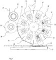
- Fig.1 is a section of a device according to the invention with a more detailed representation of a Ableverzetzwerk to see.
- the fiber material 21 is guided by a pressure roller 40 to the counter-roller 23.
- the separation roller 24 has circumferentially arranged blades 26 and release elements that are considered to be radial sliding stamp elements and are designed as holding elements 27 with integrated holding area, on. In this case they are designed as vacuum holding elements.
- One of the knives 26 is currently separating a section 22 of fibrous material.
- the counter-roller 23 has matching recesses 29 into which the respective knife 26 engages.
- the recess 29 may be free such that the fibers of the fibrous material are broken over the knife edge, or it may be filled with an elastic material, eg a rubber cord, so that the fibers of the fibrous material are cut by the pressure on the knife edge.
- Another section 22 is moved by a further holding element 27 with the roller circumference.
- the holding members 27 are provided with a vacuum port 33 and are sucked to hold the portion 22 on the roller.
- Yet another section 22 is already on the board carrier, which is formed by the table 5, filed. He was by a holding member 27, which was pressed by a spring member 32 to the outside, moved away from the roll circumference 28, provided with a pulse and transmitted to the table 25.
- the vacuum supply was interrupted so that the portion 22 detaches from the holding member 27.
- a short burst of compressed air could also be applied through the vacuum openings of the holding element 27 in order to detach the section 22.
- a binder applicator 34 is shown that can meter binder material onto the support members 27.
- the direction of movement Y of the table 5, in which it is movable, is aligned perpendicular to the page level.
- the sections 2 are deposited transversely to the main fiber direction of the fiber material 1.
- the length of a section is A.
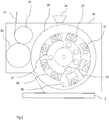
- Fig.2 is a section like in Fig.1 shown, wherein the Able trimming is performed with a slotted guide 36 for the control of the holding elements 27.
- Each holding element 27 has a roller 31, which is preferably rotatably mounted in the holding element.
- the spring elements 32 push the holding elements 27 outwardly until the respective roller 31 abuts against the stop edge 39 of the slotted guide 36.
- a step jump 38 in the region of the deposit position causes the spring-loaded retaining elements 27 at this point after fast outside and beat against the stop edge 39.
- the portion 22 is moved away from the roll circumference 28 and placed on the table 5 with a pulse.
- the vacuum supply takes place via a stationary vacuum pipe 37, which is connected to a vacuum source.
- the vacuum port 37 covers the vacuum ports 33 in the area in which the sections 22 are to be held. In the area of depositing, the vacuum ports 33 are released, so that the holding elements 27 are vented and the holding force disappears.
- the section 22 can detach from the retaining element 27 and is deposited in the manner described above.
- a compressed air connection can supply air into the holding elements, so that the sections 22 can be blown off the holding element.
- the laterally spirally executed abutment edge 39 pushes the retaining elements 27 via their roller 31 back to their original position.
- the slide guide 36 may be present on one side or preferably on the front and back of the device. By a two-sided execution tilting of the holding elements 27 is reliably avoided.
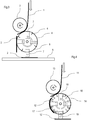
- FIG. 3 shows a simplified schematic representation of a section of another device according to the invention.
- the fiber material 1 is fed to the Able trimming plant.
- the sections 2 are cut by the knives 6.
- the release elements are designed as stamp elements and as holding elements 7.
- the holding elements 7 are radially displaceable.
- the portion 2 is moved away from the holding surface 7 of the roll surface 8, the holding force, for example, the vacuum force is reduced and placed the section 2 on the table 5.
- the holding force is not reduced, but is overcome by the influence of the release element and / or by an attraction force of a transfer unit or the platinum carrier. In particular, when using electrostatic attraction as a holding force can to follow this concept.
- a minimum distance when depositing greater than 0 mm, in particular between 1 and 10 mm, is provided between the detachment element (holding element 7) and the platinum carrier (table 5).
- the deposition in the other embodiments described may also be made at a distance greater than 0 mm and without direct contact.
- the table may be designed so that it exerts a holding force on the deposited portions, for example, it may be designed as a vacuum table with evacuated surface or with electrostatic charge.
- the stamp elements, here embodied as holding elements 7, may be arranged eccentrically between two knives 6, particularly preferably such that the holding element 7 is displaced against the direction of rotation of the separating roll 4 towards the adjacent knife 6. As a result, the sections 2 are well fixed during cutting.
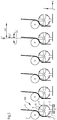
- FIG 4 another embodiment of a Able trimming plant is shown.
- the holding force shown as radially inwardly drawn arrows, may be generated by, for example, vacuum or electrostatic attraction. It can be present between two blades 6 as shown two holding areas each adjacent to the release element.
- the representation in Figure 5 shows a device according to the invention with six Ableneidwerken 100.
- the same elements in the schematic representation are provided with the same reference numerals.
- the depositing plants 100 are displaceable by small travel paths ⁇ X, ⁇ Y, ⁇ Z, which are preferably smaller than a section length A. In addition, they may also be rotatable about the Z axis ( ⁇ C). The smaller the distances between two Ablewechstechniken 100, the more closed, the sections can be stored in one operation.
- a sideways movement in the X direction may take place so that the gaps are filled with sections.
- the platinum carrier could also first be moved in the Y direction and then a sideways movement in the X direction be made in order to fill in the gaps.
- FIG 6 is a device according to the invention with 12 Ablelegewerken 100,200 - arranged in two rows one behind the other - to see.
- the entire depositing width B can be stored simultaneously. Due to the staggered arrangement of the Able-cutters on the gap there is enough space for the drive and supply devices of the Able-cutters.
- the platinum carrier By moving the platinum carrier (not shown) in the Y direction, here perpendicular to the plane of the page, the sections can be laid flat closed, without having to move the depositing units into their position.
- the displacement movement of the platinum carrier is advantageously adapted to the clock rate of the Able-making plants, so that exactly the respective gaps between already deposited sections are filled.
- a targeted overlap or a specific gap between the deposited sections in a fiber layer can be generated.
- the individual Able-cutters can be designed so that they can be controlled individually in speed, travel and spreading.
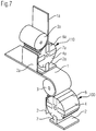
- Figure 7 shows a Able-tailing plant 100 with an additional Able-tailings 110, which is arranged transversely in the axes of the rollers 3a, 4a, in particular perpendicular to the axes of the rollers 3.4.
- the orientation of the additional Able trimming work 110 may also be oblique, so that between the two sections another angle than 90 ° arises.
- one of the fibrous materials 1,1a may contain binder or matrix material or it may be applied by a binder applicator.
- Figure 8 is a perspective view of a device according to the invention. Again, there are twelve Able-cutters 100, 200 arranged in two rows one behind the other. It can be seen how a closed fiber layer of sections 2 can be produced by the displacement of the platinum carrier, here the table 5 in the Y direction. After a first fiber layer, one or even numerous further fiber layers can be deposited from sections 2 on the first fiber layer. Between the laying down of the fiber layers, the table 5 can be rotated about the Z-axis (+/- C) or additionally be displaced in the X-direction. Thus, a desired fiber structure can be constructed very flexibly.
- a movement of the table 5 in the Z direction is possible, for example, to change the distance between the Ableneidwerken 100,200 and the board carrier.
- a movement of the table 5 in the Z direction is possible, for example, to change the distance between the Ableneidtechniken 100,200 and the board carrier.
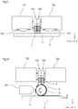
- FIG. 9 shows a schematic side view.
- a first row of lay-off units 100 and a second row of leveling units 200 are arranged directly one behind the other.
- respective binder application devices 130 and / or 230 may be present, which can apply binder material to the deposited sections 2.
- Binder applicators may also be present in the other embodiments described above and below.
- Figure 10 represents a further device according to the invention with transfer unit 9. It is again a side view.
- the sections are not deposited directly on the serving as a platinum support table 5, but initially only on the surface of the transfer unit 9.
- the transfer unit 9 can be used as a suction roll, vacuum conveyor belt or other roller or conveyor belt, which Be held sections and deliver again, be executed.
- an internal vacuum cover is provided, which ensures that the sections 2 can be transferred from the transfer unit 9 to the table 5.
- the platinum carrier so here the table 5, is designed such that it attracts and fixes the sections with electrostatic charge or vacuum.
- a binder application device 330 can apply binder material to the sections on the transfer unit 9. Alternatively, the binder application devices shown above can also be used. The advantages of such a transfer unit have already been mentioned above.
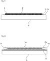
- Fig. 11 shows a possible fiber board 20 having a plurality of fiber layers, which are each constructed of sections 2 deposited with a device according to the invention.
- the sections 2 have been deposited in this case on a film 25, which serves as a platinum carrier.
- the film 25 is in turn on a support plate 15 a, which is connected to the table 5 a.
- the support plate 15a can be detached from the table 5a.
- a new carrier plate is placed.
- Figure 12 a variant can be seen in which the stored and possibly fixed with binder material or already impregnated with matrix material fiber board 20 between two sheets 25 and 25a is arranged.
- a seal 30 is provided all around between the foils.
- the fiber board 20 is evacuated between the films, it can be very well transported together with the carrier plate and then be formed for example in a forming device.
- carrier plates 15a By using carrier plates 15a, a largely automated transport between the working steps in a production line can be realized.
- FIGS. 11 and 12 Variants shown are applicable to all shown and described embodiments.
- the sections can be stored without intermediate film on a support plate, which then serves as a platinum carrier.
Landscapes
- Engineering & Computer Science (AREA)
- Mechanical Engineering (AREA)
- Life Sciences & Earth Sciences (AREA)
- Forests & Forestry (AREA)
- Nonwoven Fabrics (AREA)
- Treatment Of Fiber Materials (AREA)
- Processing And Handling Of Plastics And Other Materials For Molding In General (AREA)
- Preliminary Treatment Of Fibers (AREA)
Claims (15)
- Dispositif pour la fabrication de platines de fibres (20), présentant un support de platines (5, 15, 25) et plusieurs, au moins quatre, mécanismes de coupe (100, 200) pour couper un matériau de fibres (1, 11, 21), en particulier un matériau de fibres en forme de cordon ou de bande, en portions (2, 12, 22) et pour déposer les portions (2, 12, 22),
dans lequel ces mécanismes de coupe-dépôt (100, 200) présentent chacun un cylindre de coupe (4, 14, 24) avec plusieurs couteaux (6, 16, 26, 46) disposés à la périphérie cylindrique du cylindre de coupe (4, 14, 24) et chacun un cylindre opposé (3, 13, 23), qui peuvent tourner en sens contraire et qui sont disposés de telle manière que le matériau de fibres (1, 11, 21) puisse être conduit entre le cylindre de coupe (4, 14, 24) et le cylindre opposé (3, 13, 23) et ainsi être coupé par un des couteaux (6, 16, 26, 46) en coopération avec le cylindre opposé (3, 13, 23), de telle manière qu'il se forme ainsi une portion (2, 12, 22),
dans lequel il se trouve sur le cylindre opposé (3, 13, 23) ou sur le cylindre de coupe (4, 14, 24) plusieurs zones de maintien intégrées (7, 17, 27) et plusieurs éléments de décollement (7, 19, 27), réalisés de telle manière qu'au moins une des zones de maintien (7, 17, 27) puisse respectivement exercer une force de maintien sur une portion respective (2, 12, 22), par laquelle la portion (2, 12, 22) peut être maintenue sur le cylindre (3, 13, 23, 4, 14, 24) avec les zones de maintien et qu'après la coupe une pièce puisse être entraînée avec la périphérie cylindrique de ce cylindre (3, 13, 23, 4, 14, 24), et dans lequel les éléments de décollement (7, 19, 27) sont réalisés de telle manière qu'ils puissent pour le dépôt éloigner la portion (2, 12, 22) de la périphérie cylindrique (8, 28) et de telle manière que la portion respective (2, 12, 22) puisse être déposée après l'entraînement sur le cylindre,
dans lequel le support de platines (5, 15, 25) peut être déplacé sous les mécanismes de coupe-dépôt (100, 200) dans au moins une direction de mouvement (Y),
et dans lequel les mécanismes de coupe-dépôt (100, 200) sont disposés de façon essentiellement stationnaire et l'un à côté de l'autre, de telle manière que les portions (2, 12, 22) de ces mécanismes de coupe-dépôt (100, 200) puissent être déposées simultanément l'une à côté de l'autre sur le support de platines (5, 15, 25). - Dispositif selon la revendication 1, caractérisé en ce qu'il est prévu une ou plusieurs unité(s) de transfert (9), qui est/sont réalisée(s) de telle manière que les portions respectives (2, 2a, 12, 22) puissent être d'abord déposées par les éléments de décollement (7, 7a, 19, 27) sur la surface de l'unité de transfert (9) et transférées de celle-ci sur le support de platines (5, 15, 25).
- Dispositif selon la revendication 1 ou 2, caractérisé en ce qu'il est réalisé de telle manière que la plus petite distance lors du dépôt entre un élément de tampon (7, 7a, 19, 27) et le support de platines (5, 15, 25) ou entre un élément de décollement (7, 7a, 19, 27) et la surface de l'unité de transfert (9) se situe entre 0 et 70 mm, de préférence entre 1 et 10 mm.
- Dispositif selon l'une quelconque des revendications précédentes, caractérisé en ce qu'il est prévu un ou plusieurs dispositif(s) d'application de liant (34, 130, 230, 330), qui est/sont disposé (s) de telle manière qu'il(s) puisse(nt) appliquer un matériau liant sur les portions avant ou après le dépôt sur le support de platines (5, 15, 25).
- Dispositif selon l'une quelconque des revendications précédentes, caractérisé en ce que les éléments de décollement sont réalisés sous la forme d'éléments de tampon (7, 7a, 19, 27) déplaçables essentiellement radialement et/ou sont réalisés sous la forme d'éléments de maintien (7, 7a, 27) avec une zone de maintien intégrée.
- Dispositif selon l'une quelconque des revendications précédentes, caractérisé en ce que les zones de maintien (7, 7a, 17, 27) et le cylindre correspondant sont réalisés de telle manière que la force de maintien puisse être produite par le vide ou par attraction électrostatique.
- Dispositif selon l'une quelconque des revendications précédentes, caractérisé en ce que les mécanismes de coupe-dépôt (100, 200) sont disposés l'un derrière l'autre en deux ou plusieurs rangées dans la direction de mouvement (Y) du support de platines (5, 15, 25), en particulier en ce que les mécanismes de coupe-dépôt (100) d'une rangée sont disposés en quinconce par rapport aux mécanismes de coupe-dépôt (200) de l'autre rangée.
- Dispositif selon l'une quelconque des revendications précédentes, caractérisé en ce que les mécanismes de coupe-dépôt (100, 200) peuvent être déplacés dans leur position stationnaire de petites courses (ΔX, ΔY, ΔZ), qui sont plus courtes que la longueur A des portions, et/ou peuvent être tournés (ΔC) autour de l'axe virtuel Z perpendiculaire au support de platines (5, 15, 25).
- Dispositif selon l'une quelconque des revendications précédentes, caractérisé en ce que les mécanismes de coupe-dépôt (100, 200) peuvent être commandés individuellement.
- Dispositif selon l'une quelconque des revendications précédentes, caractérisé en ce que le support de platines (5, 15, 25) peut en outre être déplacé aussi transversalement à la direction de mouvement (Y) dans la direction X et/ou suivant la hauteur Z et/ou peut être tourné autour de l'axe virtuel Z perpendiculaire au support de platines (5, 15, 25).
- Dispositif selon l'une quelconque des revendications précédentes, caractérisé en ce que le support de platines est réalisé sous la forme d'une plaque de support (15) ou d'une feuille (25), qui est disposée sur une table (5a) déplaçable dans au moins une direction de mouvement (Y).
- Dispositif selon l'une quelconque des revendications précédentes, caractérisé en ce qu'il se trouve des mécanismes de coupe-dépôt supplémentaires (110), qui sont aptes à couper un matériau de fibres (1a) en portions (2a) et à déposer ces portions (2a) sur le matériau de fibres (1) avant ou lors de l'engagement dans le mécanisme de coupe-dépôt (100, 200).
- Procédé pour la fabrication de platines de fibres (20) avec utilisation d'un dispositif selon l'une quelconque des revendications précédentes, dans lequel on exécute successivement les étapes suivantes a)-d):a) couper une portion respective (2, 2a, 12, 22) du matériau de fibres (1, 1a, 11, 21) simultanément dans les multiples mécanismes de coupe-dépôt,b) maintenir la portion respective (2, 2a, 12, 22) sur le cylindre opposé (3, 3a, 13, 23) ou sur le cylindre de coupe (4, 4a, 14, 24) et entraîner la portion (2, 2a, 12, 22) avec la périphérie cylindrique (8, 28) de ce cylindre simultanément dans les multiples mécanismes de coupe-dépôt,c) déposer l'une à côté de l'autre les portions respectives (2, 2a, 12, 22) simultanément à travers les multiples mécanismes de coupe-dépôt, etd) déplacer le support de platines (5, 15, 25) dans au moins une direction de mouvement (Y),e) répéter plusieurs fois les étapes a)-d), de telle manière qu'une couche de portions (2, 2a, 12, 22) soit produite sur le support de platines (5, 15, 25),et dans lequel on produit une ou plusieurs autres couches de portions (2, 2a, 12, 22) sur la première couche, en répétant les étapes a)-e).
- Procédé selon la revendication 13, caractérisé en ce que l'on applique un matériau liant sur les portions (2, 2a, 12, 22) après le dépôt, dans lequel on effectue cette application de liant en particulier entre l'étape c) et l'étape d) ou en particulier après l'étape e) et avant le dépôt d'une autre couche.
- Procédé selon la revendication 13 ou 14, caractérisé en ce que l'on déplace le support de platines (5, 15, 25) après l'étape e) et avant le dépôt d'une autre couche dans une direction (X) transversale à la direction de mouvement (Y) et/ou on le fait tourner dans une direction (C) autour de l'axe virtuel Z perpendiculaire au support de platines.
Applications Claiming Priority (3)
| Application Number | Priority Date | Filing Date | Title |
|---|---|---|---|
| DE102013224835.0A DE102013224835A1 (de) | 2013-12-04 | 2013-12-04 | Walzenschneidwerk zum Trennen von Fasermaterial in Abschnitte |
| DE102014221085.2A DE102014221085A1 (de) | 2014-10-17 | 2014-10-17 | Vorrichtung und Verfahren zum Trennen und Ablegen von Fasermaterial |
| PCT/EP2014/076066 WO2015082385A1 (fr) | 2013-12-04 | 2014-12-01 | Dispositif et procédé pour la fabrication de platines de fibres |
Publications (2)
| Publication Number | Publication Date |
|---|---|
| EP3077308A1 EP3077308A1 (fr) | 2016-10-12 |
| EP3077308B1 true EP3077308B1 (fr) | 2018-02-21 |
Family
ID=52007004
Family Applications (2)
| Application Number | Title | Priority Date | Filing Date |
|---|---|---|---|
| EP14806594.9A Not-in-force EP3077308B1 (fr) | 2013-12-04 | 2014-12-01 | Dispositif et procédé pour la fabrication de platines de fibres |
| EP14809610.0A Not-in-force EP3077166B1 (fr) | 2013-12-04 | 2014-12-01 | Mécanisme de découpage à cylindres et procédé de découpage d'une matière fibreuse en segments |
Family Applications After (1)
| Application Number | Title | Priority Date | Filing Date |
|---|---|---|---|
| EP14809610.0A Not-in-force EP3077166B1 (fr) | 2013-12-04 | 2014-12-01 | Mécanisme de découpage à cylindres et procédé de découpage d'une matière fibreuse en segments |
Country Status (5)
| Country | Link |
|---|---|
| US (2) | US20160368168A1 (fr) |
| EP (2) | EP3077308B1 (fr) |
| CN (2) | CN105916788B (fr) |
| ES (1) | ES2681275T3 (fr) |
| WO (2) | WO2015082385A1 (fr) |
Families Citing this family (16)
| Publication number | Priority date | Publication date | Assignee | Title |
|---|---|---|---|---|
| CN107444961B (zh) * | 2017-08-06 | 2019-08-30 | 慈溪市金山密封设备有限公司 | 一种用于加工金属缠绕件的金属片送料系统 |
| DE102017216133A1 (de) * | 2017-09-13 | 2019-03-14 | Robert Bosch Gmbh | Verfahren zum Trennen bandförmigen Elektroden- und Separatormaterials auf einer gekrümmten Oberfläche |
| DE102017216138A1 (de) * | 2017-09-13 | 2019-03-14 | Robert Bosch Gmbh | Verfahren zur Herstellung eines Elektrodenstapels für eine Batteriezelle und Batteriezelle |
| DE102018200553A1 (de) * | 2018-01-15 | 2019-07-18 | Robert Bosch Gmbh | Elektrodenanordnung und Verfahren zum Herstellen einer solchen |
| CN111936281B (zh) * | 2018-04-04 | 2022-04-29 | 三菱化学株式会社 | 纤维增强树脂成型材料的制造方法和纤维增强树脂成型材料的制造装置 |
| EP3647037A1 (fr) | 2018-10-30 | 2020-05-06 | Profol Kunststoffe GmbH | Dispositif et procédé de fabrication de x ruban / x bande de demi-produit au moyen de procédé de soudage en spirale et de coupe |
| EP3647036B1 (fr) | 2018-10-30 | 2023-06-07 | Profol Kunststoffe GmbH | Couche d'enroulement sans fin renforcée par des fibres unidirectionnelles |
| DE102019203383A1 (de) | 2019-03-13 | 2020-09-17 | Zf Friedrichshafen Ag | Verfahren und System zum Erzeugen eines Faservorformlings |
| DE102019126583A1 (de) * | 2019-10-02 | 2021-04-08 | Hauni Maschinenbau Gmbh | Bereitstellen von Metallbandabschnitten für Tabaksegmente |
| CN111347763A (zh) * | 2020-03-21 | 2020-06-30 | 长兴创智科技有限公司 | 一种服装面料连续彩印工艺 |
| CN111267472A (zh) * | 2020-03-21 | 2020-06-12 | 长兴创智科技有限公司 | 一种服装面料全自动印花设备 |
| CN111362030A (zh) * | 2020-03-21 | 2020-07-03 | 长兴创智科技有限公司 | 一种面料连续彩印系统 |
| GB2600118B (en) * | 2020-10-21 | 2025-02-19 | Mclaren Automotive Ltd | Tape Deposition System |
| US11618177B1 (en) | 2022-04-12 | 2023-04-04 | Bradley W Boesel | Orbital knife |
| CN116276102B (zh) * | 2023-02-14 | 2024-03-12 | 江苏三环奥纳科技有限公司 | 一种非晶带材表面处理设备 |
| CN118223158B (zh) * | 2024-05-23 | 2024-09-03 | 晋江市港益纤维制品有限公司 | 涤纶短纤切割装置及涤纶短纤的切割方法 |
Family Cites Families (22)
| Publication number | Priority date | Publication date | Assignee | Title |
|---|---|---|---|---|
| FR2176580B1 (fr) * | 1972-03-24 | 1976-10-29 | Saint Gobain Pont A Mousson | |
| US3847710A (en) * | 1972-04-26 | 1974-11-12 | Mo Och Domsjoe Ab | Apparatus for applying securing tabs to diapers, sanitary towels, compresses and similar absorbent bodies |
| US4181555A (en) * | 1978-02-07 | 1980-01-01 | B & H Manufacturing Company, Inc. | Labeling apparatus and method for continuously severing labels from continuous label stock and applying the severed labels to containers |
| DE4130269C2 (de) * | 1990-09-13 | 1996-05-23 | Toshiba Machine Co Ltd | Verfahren und Vorrichtung zum Herstellen laminierter Prepreg-Teile |
| US5222422A (en) * | 1991-12-23 | 1993-06-29 | R.A. Jones & Co. Inc. | Wide range pouch form, fill, seal apparatus |
| DE59303694D1 (de) * | 1992-02-08 | 1996-10-17 | Hoechst Ag | Verfahren und Vorrichtung zum kontinuierlichen Zerschneiden von band- oder strangförmigem Gut |
| EP0606830A1 (fr) | 1993-01-15 | 1994-07-20 | GFM Gesellschaft für Fertigungstechnik und Maschinenbau Aktiengesellschaft | Procédé de fabrication d'une plaque préimprégnée plastique renforcée de fibres |
| WO1995015901A1 (fr) * | 1993-12-08 | 1995-06-15 | Beloit Technologies, Inc. | Procede et appareil de changement de lot dans un enrouleur de papier |
| US5776289A (en) * | 1995-09-29 | 1998-07-07 | Tamarack Products, Inc. | Apparatus and method for applying labels using static electrical attraction |
| US5716478A (en) * | 1995-10-17 | 1998-02-10 | Kimberly-Clark Worldwide, Inc. | Apparatus and method for applying discrete parts onto a moving web |
| US6086694A (en) * | 1997-04-01 | 2000-07-11 | Stanley Lerner | High speed web machine |
| ITBO20020259A1 (it) | 2002-05-03 | 2003-11-03 | Gd Spa | Dispositivo di arricciatura |
| JP4012042B2 (ja) * | 2002-11-01 | 2007-11-21 | 株式会社瑞光 | 着用物品の製造装置 |
| JP4745061B2 (ja) | 2004-02-05 | 2011-08-10 | 株式会社瑞光 | ウエブの加工装置 |
| ITBO20040522A1 (it) | 2004-08-09 | 2004-11-09 | Gd Spa | Unita' per l'alimentazione ed il taglio in spezzoni di un nastro di materiale d'incarto |
| US7975584B2 (en) | 2007-02-21 | 2011-07-12 | Curt G. Joa, Inc. | Single transfer insert placement method and apparatus |
| DE102008033736A1 (de) | 2008-07-18 | 2010-01-21 | Windmöller & Hölscher Kg | Vorrichtung und Verfahren zum Auf- und/oder Abwickeln von Materialbahnen |
| US8100253B2 (en) * | 2009-06-30 | 2012-01-24 | The Procter & Gamble Company | Methods and apparatuses for transferring discrete articles between carriers |
| JP5492628B2 (ja) * | 2010-03-26 | 2014-05-14 | ユニ・チャーム株式会社 | 受け渡し装置 |
| US8820513B2 (en) * | 2012-04-16 | 2014-09-02 | The Procter & Gamble Company | Methods for transferring discrete articles |
| US9731489B2 (en) * | 2013-05-29 | 2017-08-15 | H.B. Fuller Company | Material application system |
| DE102013224835A1 (de) | 2013-12-04 | 2015-06-11 | Audi Ag | Walzenschneidwerk zum Trennen von Fasermaterial in Abschnitte |
-
2014
- 2014-12-01 WO PCT/EP2014/076066 patent/WO2015082385A1/fr not_active Ceased
- 2014-12-01 CN CN201480073594.7A patent/CN105916788B/zh not_active Expired - Fee Related
- 2014-12-01 EP EP14806594.9A patent/EP3077308B1/fr not_active Not-in-force
- 2014-12-01 US US15/102,007 patent/US20160368168A1/en not_active Abandoned
- 2014-12-01 ES ES14809610.0T patent/ES2681275T3/es active Active
- 2014-12-01 EP EP14809610.0A patent/EP3077166B1/fr not_active Not-in-force
- 2014-12-01 WO PCT/EP2014/076070 patent/WO2015082387A1/fr not_active Ceased
- 2014-12-01 US US15/102,009 patent/US10456949B2/en not_active Expired - Fee Related
- 2014-12-01 CN CN201480073450.1A patent/CN105916644B/zh not_active Expired - Fee Related
Also Published As
| Publication number | Publication date |
|---|---|
| WO2015082387A1 (fr) | 2015-06-11 |
| US20160368168A1 (en) | 2016-12-22 |
| CN105916788B (zh) | 2019-01-15 |
| WO2015082385A1 (fr) | 2015-06-11 |
| US20160368729A1 (en) | 2016-12-22 |
| EP3077308A1 (fr) | 2016-10-12 |
| EP3077166B1 (fr) | 2018-06-13 |
| ES2681275T3 (es) | 2018-09-12 |
| US10456949B2 (en) | 2019-10-29 |
| CN105916788A (zh) | 2016-08-31 |
| CN105916644A (zh) | 2016-08-31 |
| EP3077166A1 (fr) | 2016-10-12 |
| CN105916644B (zh) | 2019-01-08 |
Similar Documents
| Publication | Publication Date | Title |
|---|---|---|
| EP3077308B1 (fr) | Dispositif et procédé pour la fabrication de platines de fibres | |
| EP3509830B1 (fr) | Procédé et dispositif de pose de bande comportant un dispositif de coupe pivotant | |
| EP3377308B1 (fr) | Installation de fabrication pour poser des bandes de fibres | |
| EP3386735B1 (fr) | Dispositif de dépôt pour des mèches de fibres | |
| DE102011109698B4 (de) | Verfahren zum Herstellen eines harzimprägnierten Faserhalbzeugs | |
| EP3529185B1 (fr) | Dispositif et procédé de pose de bande permettant une pose flexible et rapide de bandes de différentes largeurs | |
| WO2013131896A1 (fr) | Application transversale de fibres | |
| DE102013224835A1 (de) | Walzenschneidwerk zum Trennen von Fasermaterial in Abschnitte | |
| DE202017105285U1 (de) | Tapelegevorrichtung mit selektiver Einschneideeinrichtung | |
| DE102014221085A1 (de) | Vorrichtung und Verfahren zum Trennen und Ablegen von Fasermaterial | |
| EP3814121B1 (fr) | Procédé et dispositif de production de pièces comportant un matériau composite renforcé de fibres | |
| DE202016105889U1 (de) | Vorrichtung zur Aufnahme von Tapes und Tapelegevorrichtung | |
| DE202016106067U1 (de) | Tapelegevorrichtung zum Aufbau eines Laminats im Zuge der Herstellung von Vorformlingen | |
| EP2450481B1 (fr) | Dispositif et procédé de fabrication de machines mono- et multiaxiales | |
| DE102016116874A1 (de) | Tapelegevorrichtung und Tapelegeverfahren | |
| DE202016104945U1 (de) | Tapelegevorrichtung zum simultanen Legen von Tapes mit variablem Abstand | |
| DE102016116799A1 (de) | Tapelegevorrichtung und Tapelegeverfahren zum simultanen Legen von Tapes mit variablem Abstand | |
| EP3529060A1 (fr) | Dispositif de pose de bandes et procédé de pose de bandes pour la pose souple et rapide de bandes présentant une durée de cycle courte | |
| DE202016105861U1 (de) | Tapelegevorrichtung zum flexiblen und schnellen Legen von Tapes mit kurzer Zykluszeit | |
| DE202016105860U1 (de) | Tapelegevorrichtung mit verschwenkbarer Schneideinrichtung | |
| DE202016104965U1 (de) | Tapelegevorrichtung | |
| DE202016105871U1 (de) | Tapelegevorrichtung zum flexiblen und schnellen Legen von Tapes mit unterschiedlicher Breite | |
| DE102016119902A1 (de) | Legetisch zur Aufnahme eines Materials | |
| DE102016119954A1 (de) | Vorrichtung zur Aufnahme eines Tapes und Tapelegevorrichtung | |
| DE102015218212A1 (de) | Vorrichtung und Verfahren zur Herstellung eines faserverstärkten Verbundbauteils |
Legal Events
| Date | Code | Title | Description |
|---|---|---|---|
| PUAI | Public reference made under article 153(3) epc to a published international application that has entered the european phase |
Free format text: ORIGINAL CODE: 0009012 |
|
| 17P | Request for examination filed |
Effective date: 20160704 |
|
| AK | Designated contracting states |
Kind code of ref document: A1 Designated state(s): AL AT BE BG CH CY CZ DE DK EE ES FI FR GB GR HR HU IE IS IT LI LT LU LV MC MK MT NL NO PL PT RO RS SE SI SK SM TR |
|
| AX | Request for extension of the european patent |
Extension state: BA ME |
|
| DAX | Request for extension of the european patent (deleted) | ||
| REG | Reference to a national code |
Ref country code: DE Ref legal event code: R079 Ref document number: 502014007370 Country of ref document: DE Free format text: PREVIOUS MAIN CLASS: B65H0035080000 Ipc: B29B0011160000 |
|
| GRAP | Despatch of communication of intention to grant a patent |
Free format text: ORIGINAL CODE: EPIDOSNIGR1 |
|
| RIC1 | Information provided on ipc code assigned before grant |
Ipc: B26D 7/01 20060101ALN20170609BHEP Ipc: B29B 11/16 20060101AFI20170609BHEP Ipc: B65H 35/08 20060101ALN20170609BHEP Ipc: B26D 1/40 20060101ALN20170609BHEP Ipc: B65H 29/24 20060101ALN20170609BHEP |
|
| INTG | Intention to grant announced |
Effective date: 20170704 |
|
| GRAS | Grant fee paid |
Free format text: ORIGINAL CODE: EPIDOSNIGR3 |
|
| GRAA | (expected) grant |
Free format text: ORIGINAL CODE: 0009210 |
|
| AK | Designated contracting states |
Kind code of ref document: B1 Designated state(s): AL AT BE BG CH CY CZ DE DK EE ES FI FR GB GR HR HU IE IS IT LI LT LU LV MC MK MT NL NO PL PT RO RS SE SI SK SM TR |
|
| REG | Reference to a national code |
Ref country code: GB Ref legal event code: FG4D Free format text: NOT ENGLISH |
|
| REG | Reference to a national code |
Ref country code: CH Ref legal event code: EP |
|
| REG | Reference to a national code |
Ref country code: AT Ref legal event code: REF Ref document number: 971214 Country of ref document: AT Kind code of ref document: T Effective date: 20180315 |
|
| REG | Reference to a national code |
Ref country code: IE Ref legal event code: FG4D Free format text: LANGUAGE OF EP DOCUMENT: GERMAN |
|
| REG | Reference to a national code |
Ref country code: DE Ref legal event code: R096 Ref document number: 502014007370 Country of ref document: DE |
|
| REG | Reference to a national code |
Ref country code: NL Ref legal event code: MP Effective date: 20180221 |
|
| REG | Reference to a national code |
Ref country code: LT Ref legal event code: MG4D |
|
| PG25 | Lapsed in a contracting state [announced via postgrant information from national office to epo] |
Ref country code: FI Free format text: LAPSE BECAUSE OF FAILURE TO SUBMIT A TRANSLATION OF THE DESCRIPTION OR TO PAY THE FEE WITHIN THE PRESCRIBED TIME-LIMIT Effective date: 20180221 Ref country code: CY Free format text: LAPSE BECAUSE OF FAILURE TO SUBMIT A TRANSLATION OF THE DESCRIPTION OR TO PAY THE FEE WITHIN THE PRESCRIBED TIME-LIMIT Effective date: 20180221 Ref country code: NL Free format text: LAPSE BECAUSE OF FAILURE TO SUBMIT A TRANSLATION OF THE DESCRIPTION OR TO PAY THE FEE WITHIN THE PRESCRIBED TIME-LIMIT Effective date: 20180221 Ref country code: LT Free format text: LAPSE BECAUSE OF FAILURE TO SUBMIT A TRANSLATION OF THE DESCRIPTION OR TO PAY THE FEE WITHIN THE PRESCRIBED TIME-LIMIT Effective date: 20180221 Ref country code: ES Free format text: LAPSE BECAUSE OF FAILURE TO SUBMIT A TRANSLATION OF THE DESCRIPTION OR TO PAY THE FEE WITHIN THE PRESCRIBED TIME-LIMIT Effective date: 20180221 Ref country code: NO Free format text: LAPSE BECAUSE OF FAILURE TO SUBMIT A TRANSLATION OF THE DESCRIPTION OR TO PAY THE FEE WITHIN THE PRESCRIBED TIME-LIMIT Effective date: 20180521 Ref country code: HR Free format text: LAPSE BECAUSE OF FAILURE TO SUBMIT A TRANSLATION OF THE DESCRIPTION OR TO PAY THE FEE WITHIN THE PRESCRIBED TIME-LIMIT Effective date: 20180221 |
|
| PG25 | Lapsed in a contracting state [announced via postgrant information from national office to epo] |
Ref country code: BG Free format text: LAPSE BECAUSE OF FAILURE TO SUBMIT A TRANSLATION OF THE DESCRIPTION OR TO PAY THE FEE WITHIN THE PRESCRIBED TIME-LIMIT Effective date: 20180521 Ref country code: RS Free format text: LAPSE BECAUSE OF FAILURE TO SUBMIT A TRANSLATION OF THE DESCRIPTION OR TO PAY THE FEE WITHIN THE PRESCRIBED TIME-LIMIT Effective date: 20180221 Ref country code: LV Free format text: LAPSE BECAUSE OF FAILURE TO SUBMIT A TRANSLATION OF THE DESCRIPTION OR TO PAY THE FEE WITHIN THE PRESCRIBED TIME-LIMIT Effective date: 20180221 Ref country code: SE Free format text: LAPSE BECAUSE OF FAILURE TO SUBMIT A TRANSLATION OF THE DESCRIPTION OR TO PAY THE FEE WITHIN THE PRESCRIBED TIME-LIMIT Effective date: 20180221 Ref country code: GR Free format text: LAPSE BECAUSE OF FAILURE TO SUBMIT A TRANSLATION OF THE DESCRIPTION OR TO PAY THE FEE WITHIN THE PRESCRIBED TIME-LIMIT Effective date: 20180522 |
|
| PG25 | Lapsed in a contracting state [announced via postgrant information from national office to epo] |
Ref country code: MT Free format text: LAPSE BECAUSE OF FAILURE TO SUBMIT A TRANSLATION OF THE DESCRIPTION OR TO PAY THE FEE WITHIN THE PRESCRIBED TIME-LIMIT Effective date: 20180221 |
|
| PG25 | Lapsed in a contracting state [announced via postgrant information from national office to epo] |
Ref country code: EE Free format text: LAPSE BECAUSE OF FAILURE TO SUBMIT A TRANSLATION OF THE DESCRIPTION OR TO PAY THE FEE WITHIN THE PRESCRIBED TIME-LIMIT Effective date: 20180221 Ref country code: PL Free format text: LAPSE BECAUSE OF FAILURE TO SUBMIT A TRANSLATION OF THE DESCRIPTION OR TO PAY THE FEE WITHIN THE PRESCRIBED TIME-LIMIT Effective date: 20180221 Ref country code: AL Free format text: LAPSE BECAUSE OF FAILURE TO SUBMIT A TRANSLATION OF THE DESCRIPTION OR TO PAY THE FEE WITHIN THE PRESCRIBED TIME-LIMIT Effective date: 20180221 |
|
| REG | Reference to a national code |
Ref country code: DE Ref legal event code: R097 Ref document number: 502014007370 Country of ref document: DE |
|
| PG25 | Lapsed in a contracting state [announced via postgrant information from national office to epo] |
Ref country code: DK Free format text: LAPSE BECAUSE OF FAILURE TO SUBMIT A TRANSLATION OF THE DESCRIPTION OR TO PAY THE FEE WITHIN THE PRESCRIBED TIME-LIMIT Effective date: 20180221 Ref country code: SM Free format text: LAPSE BECAUSE OF FAILURE TO SUBMIT A TRANSLATION OF THE DESCRIPTION OR TO PAY THE FEE WITHIN THE PRESCRIBED TIME-LIMIT Effective date: 20180221 Ref country code: SK Free format text: LAPSE BECAUSE OF FAILURE TO SUBMIT A TRANSLATION OF THE DESCRIPTION OR TO PAY THE FEE WITHIN THE PRESCRIBED TIME-LIMIT Effective date: 20180221 Ref country code: CZ Free format text: LAPSE BECAUSE OF FAILURE TO SUBMIT A TRANSLATION OF THE DESCRIPTION OR TO PAY THE FEE WITHIN THE PRESCRIBED TIME-LIMIT Effective date: 20180221 |
|
| PLBE | No opposition filed within time limit |
Free format text: ORIGINAL CODE: 0009261 |
|
| STAA | Information on the status of an ep patent application or granted ep patent |
Free format text: STATUS: NO OPPOSITION FILED WITHIN TIME LIMIT |
|
| 26N | No opposition filed |
Effective date: 20181122 |
|
| PG25 | Lapsed in a contracting state [announced via postgrant information from national office to epo] |
Ref country code: SI Free format text: LAPSE BECAUSE OF FAILURE TO SUBMIT A TRANSLATION OF THE DESCRIPTION OR TO PAY THE FEE WITHIN THE PRESCRIBED TIME-LIMIT Effective date: 20180221 |
|
| REG | Reference to a national code |
Ref country code: CH Ref legal event code: PL |
|
| PG25 | Lapsed in a contracting state [announced via postgrant information from national office to epo] |
Ref country code: LU Free format text: LAPSE BECAUSE OF NON-PAYMENT OF DUE FEES Effective date: 20181201 Ref country code: MC Free format text: LAPSE BECAUSE OF FAILURE TO SUBMIT A TRANSLATION OF THE DESCRIPTION OR TO PAY THE FEE WITHIN THE PRESCRIBED TIME-LIMIT Effective date: 20180221 |
|
| REG | Reference to a national code |
Ref country code: IE Ref legal event code: MM4A |
|
| REG | Reference to a national code |
Ref country code: BE Ref legal event code: MM Effective date: 20181231 |
|
| PG25 | Lapsed in a contracting state [announced via postgrant information from national office to epo] |
Ref country code: IE Free format text: LAPSE BECAUSE OF NON-PAYMENT OF DUE FEES Effective date: 20181201 |
|
| PG25 | Lapsed in a contracting state [announced via postgrant information from national office to epo] |
Ref country code: BE Free format text: LAPSE BECAUSE OF NON-PAYMENT OF DUE FEES Effective date: 20181231 |
|
| PG25 | Lapsed in a contracting state [announced via postgrant information from national office to epo] |
Ref country code: CH Free format text: LAPSE BECAUSE OF NON-PAYMENT OF DUE FEES Effective date: 20181231 Ref country code: LI Free format text: LAPSE BECAUSE OF NON-PAYMENT OF DUE FEES Effective date: 20181231 |
|
| PG25 | Lapsed in a contracting state [announced via postgrant information from national office to epo] |
Ref country code: TR Free format text: LAPSE BECAUSE OF FAILURE TO SUBMIT A TRANSLATION OF THE DESCRIPTION OR TO PAY THE FEE WITHIN THE PRESCRIBED TIME-LIMIT Effective date: 20180221 |
|
| PG25 | Lapsed in a contracting state [announced via postgrant information from national office to epo] |
Ref country code: PT Free format text: LAPSE BECAUSE OF FAILURE TO SUBMIT A TRANSLATION OF THE DESCRIPTION OR TO PAY THE FEE WITHIN THE PRESCRIBED TIME-LIMIT Effective date: 20180221 |
|
| PG25 | Lapsed in a contracting state [announced via postgrant information from national office to epo] |
Ref country code: HU Free format text: LAPSE BECAUSE OF FAILURE TO SUBMIT A TRANSLATION OF THE DESCRIPTION OR TO PAY THE FEE WITHIN THE PRESCRIBED TIME-LIMIT; INVALID AB INITIO Effective date: 20141201 Ref country code: MK Free format text: LAPSE BECAUSE OF NON-PAYMENT OF DUE FEES Effective date: 20180221 Ref country code: RO Free format text: LAPSE BECAUSE OF FAILURE TO SUBMIT A TRANSLATION OF THE DESCRIPTION OR TO PAY THE FEE WITHIN THE PRESCRIBED TIME-LIMIT Effective date: 20180221 |
|
| PG25 | Lapsed in a contracting state [announced via postgrant information from national office to epo] |
Ref country code: IS Free format text: LAPSE BECAUSE OF FAILURE TO SUBMIT A TRANSLATION OF THE DESCRIPTION OR TO PAY THE FEE WITHIN THE PRESCRIBED TIME-LIMIT Effective date: 20180621 |
|
| PGFP | Annual fee paid to national office [announced via postgrant information from national office to epo] |
Ref country code: GB Payment date: 20201223 Year of fee payment: 7 Ref country code: FR Payment date: 20201223 Year of fee payment: 7 Ref country code: DE Payment date: 20201211 Year of fee payment: 7 |
|
| REG | Reference to a national code |
Ref country code: AT Ref legal event code: MM01 Ref document number: 971214 Country of ref document: AT Kind code of ref document: T Effective date: 20191201 |
|
| PGFP | Annual fee paid to national office [announced via postgrant information from national office to epo] |
Ref country code: IT Payment date: 20201224 Year of fee payment: 7 |
|
| PG25 | Lapsed in a contracting state [announced via postgrant information from national office to epo] |
Ref country code: AT Free format text: LAPSE BECAUSE OF NON-PAYMENT OF DUE FEES Effective date: 20191201 |
|
| REG | Reference to a national code |
Ref country code: DE Ref legal event code: R119 Ref document number: 502014007370 Country of ref document: DE |
|
| GBPC | Gb: european patent ceased through non-payment of renewal fee |
Effective date: 20211201 |
|
| PG25 | Lapsed in a contracting state [announced via postgrant information from national office to epo] |
Ref country code: GB Free format text: LAPSE BECAUSE OF NON-PAYMENT OF DUE FEES Effective date: 20211201 Ref country code: DE Free format text: LAPSE BECAUSE OF NON-PAYMENT OF DUE FEES Effective date: 20220701 |
|
| PG25 | Lapsed in a contracting state [announced via postgrant information from national office to epo] |
Ref country code: FR Free format text: LAPSE BECAUSE OF NON-PAYMENT OF DUE FEES Effective date: 20211231 |
|
| PG25 | Lapsed in a contracting state [announced via postgrant information from national office to epo] |
Ref country code: IT Free format text: LAPSE BECAUSE OF NON-PAYMENT OF DUE FEES Effective date: 20211201 |