EP3077593B1 - Textile industriel à double couche non tissé assemblé à partir de panneaux configurés en manchon, et panneaux associés - Google Patents
Textile industriel à double couche non tissé assemblé à partir de panneaux configurés en manchon, et panneaux associés Download PDFInfo
- Publication number
- EP3077593B1 EP3077593B1 EP14867109.2A EP14867109A EP3077593B1 EP 3077593 B1 EP3077593 B1 EP 3077593B1 EP 14867109 A EP14867109 A EP 14867109A EP 3077593 B1 EP3077593 B1 EP 3077593B1
- Authority
- EP
- European Patent Office
- Prior art keywords
- panel
- seam
- hem
- folded
- region
- Prior art date
- Legal status (The legal status is an assumption and is not a legal conclusion. Google has not performed a legal analysis and makes no representation as to the accuracy of the status listed.)
- Active
Links
Images










Classifications
-
- D—TEXTILES; PAPER
- D21—PAPER-MAKING; PRODUCTION OF CELLULOSE
- D21F—PAPER-MAKING MACHINES; METHODS OF PRODUCING PAPER THEREON
- D21F1/00—Wet end of machines for making continuous webs of paper
- D21F1/0027—Screen-cloths
- D21F1/0036—Multi-layer screen-cloths
-
- B—PERFORMING OPERATIONS; TRANSPORTING
- B32—LAYERED PRODUCTS
- B32B—LAYERED PRODUCTS, i.e. PRODUCTS BUILT-UP OF STRATA OF FLAT OR NON-FLAT, e.g. CELLULAR OR HONEYCOMB, FORM
- B32B3/00—Layered products comprising a layer with external or internal discontinuities or unevennesses, or a layer of non-planar shape; Layered products comprising a layer having particular features of form
- B32B3/26—Layered products comprising a layer with external or internal discontinuities or unevennesses, or a layer of non-planar shape; Layered products comprising a layer having particular features of form characterised by a particular shape of the outline of the cross-section of a continuous layer; characterised by a layer with cavities or internal voids ; characterised by an apertured layer
-
- B—PERFORMING OPERATIONS; TRANSPORTING
- B65—CONVEYING; PACKING; STORING; HANDLING THIN OR FILAMENTARY MATERIAL
- B65G—TRANSPORT OR STORAGE DEVICES, e.g. CONVEYORS FOR LOADING OR TIPPING, SHOP CONVEYOR SYSTEMS OR PNEUMATIC TUBE CONVEYORS
- B65G15/00—Conveyors having endless load-conveying surfaces, i.e. belts and like continuous members, to which tractive effort is transmitted by means other than endless driving elements of similar configuration
- B65G15/30—Belts or like endless load-carriers
-
- D—TEXTILES; PAPER
- D04—BRAIDING; LACE-MAKING; KNITTING; TRIMMINGS; NON-WOVEN FABRICS
- D04H—MAKING TEXTILE FABRICS, e.g. FROM FIBRES OR FILAMENTARY MATERIAL; FABRICS MADE BY SUCH PROCESSES OR APPARATUS, e.g. FELTS, NON-WOVEN FABRICS; COTTON-WOOL; WADDING ; NON-WOVEN FABRICS FROM STAPLE FIBRES, FILAMENTS OR YARNS, BONDED WITH AT LEAST ONE WEB-LIKE MATERIAL DURING THEIR CONSOLIDATION
- D04H13/00—Other non-woven fabrics
-
- D—TEXTILES; PAPER
- D21—PAPER-MAKING; PRODUCTION OF CELLULOSE
- D21F—PAPER-MAKING MACHINES; METHODS OF PRODUCING PAPER THEREON
- D21F1/00—Wet end of machines for making continuous webs of paper
- D21F1/0027—Screen-cloths
- D21F1/0054—Seams thereof
-
- D—TEXTILES; PAPER
- D21—PAPER-MAKING; PRODUCTION OF CELLULOSE
- D21F—PAPER-MAKING MACHINES; METHODS OF PRODUCING PAPER THEREON
- D21F1/00—Wet end of machines for making continuous webs of paper
- D21F1/0027—Screen-cloths
- D21F1/0063—Perforated sheets
-
- D—TEXTILES; PAPER
- D21—PAPER-MAKING; PRODUCTION OF CELLULOSE
- D21F—PAPER-MAKING MACHINES; METHODS OF PRODUCING PAPER THEREON
- D21F1/00—Wet end of machines for making continuous webs of paper
- D21F1/0027—Screen-cloths
- D21F1/0072—Link belts
-
- D—TEXTILES; PAPER
- D21—PAPER-MAKING; PRODUCTION OF CELLULOSE
- D21F—PAPER-MAKING MACHINES; METHODS OF PRODUCING PAPER THEREON
- D21F7/00—Other details of machines for making continuous webs of paper
- D21F7/08—Felts
-
- D—TEXTILES; PAPER
- D21—PAPER-MAKING; PRODUCTION OF CELLULOSE
- D21F—PAPER-MAKING MACHINES; METHODS OF PRODUCING PAPER THEREON
- D21F7/00—Other details of machines for making continuous webs of paper
- D21F7/08—Felts
- D21F7/10—Seams thereof
-
- F—MECHANICAL ENGINEERING; LIGHTING; HEATING; WEAPONS; BLASTING
- F16—ENGINEERING ELEMENTS AND UNITS; GENERAL MEASURES FOR PRODUCING AND MAINTAINING EFFECTIVE FUNCTIONING OF MACHINES OR INSTALLATIONS; THERMAL INSULATION IN GENERAL
- F16G—BELTS, CABLES, OR ROPES, PREDOMINANTLY USED FOR DRIVING PURPOSES; CHAINS; FITTINGS PREDOMINANTLY USED THEREFOR
- F16G3/00—Belt fastenings, e.g. for conveyor belts
- F16G3/02—Belt fastenings, e.g. for conveyor belts with series of eyes or the like, interposed and linked by a pin to form a hinge
- F16G3/04—Belt fastenings, e.g. for conveyor belts with series of eyes or the like, interposed and linked by a pin to form a hinge in which the ends of separate U-shaped or like eyes are attached to the belt by parts penetrating into it
Definitions
- This article relates to industrial textiles.
- it relates to a double layer non-woven industrial textile formed from the interconnection of panels formed from suitable sheet or film materials.
- Non-woven industrial textiles formed from one or more layers of sheet or film materials have been disclosed in U.S. Patent Nos. 8,454,800 , 8,394,239 and 8,388,812 ; U.S. Patent Application Publication Nos. 2013/0081772 , 2012/0027997 ; 2012/0021171 ; 2011/0272112 and 2010/0239814 .
- These non-woven industrial textiles can be formed from a polymeric film that includes through apertures that provide porosity through the textile.
- the textiles can be produced by spirally winding strips of polymeric material and joining the adjoining sides of the strips of material using ultrasonic welding or laser welding techniques.
- a textile formed in this manner is perforated to make it permeable to air and/or water.
- such textiles are not easily seamed; and there is no internal structure that helps to maintain a separation and void volume between layers of panels.
- U.S. Patent Nos. 8,784,615 ; 8,815,057 ; and U.S. Patent Application Publication No. 2012/0021178 ; and PCT Patent Application Publication Nos. WO 2005/042836 ; WO 2008/145420 ; WO 2014/001172 ; WO 2013/010678 and WO 2012/123439 all disclose various arrangements to provide a continuous belt for use as an industrial textile; in particular, as a papermaking fabric.
- the fabric is formed from one or more lengthwise oriented strips of a perforated film material that are joined edge to edge.
- such arrangements may not readily provide adequate flexibility and permeability of the entire non-woven industrial textile.
- the component strips are difficult to assemble and seam.
- U.S. Patent No. 8,563,114 discloses an industrial textile formed from two interconnected layers of a polymer film that is contoured by an embossing process that raises portions of the film above its general plane. Slits are then precision cut through the film to create apertures in the raised portions to provide for liquid drainage or air passage through the textile.
- Each layer of film is selectively slit and embossed to provide a plurality of regularly arranged protrusions extending from a first planar surface of the film outwardly from the opposing second surface and in which protrusions the apertures are located.
- the resulting textile is formed from a plurality of similarly profiled strips of film interconnected to provide a two layer film assembly.
- the strips are either offset over one another and interconnected by bonding, butt joined along the longitudinal side edges by a welding or similar bonding process, or are interconnected by inserting a filamentary material across their width through aligned apertures passing through arrays of similar protrusions.
- the resulting textile is then rendered endless and seamed using a seaming element such as disclosed in US 2012/0040150 , or other similar seaming elements.
- CA 2749477 A1 discloses a seaming element for an industrial textile, a textile with seaming elements, and a method.
- the seaming element has first and second end regions a fold line in an intermediate fold region, and outer and inner surfaces: Each end region comprises slits extending from the outer surface through the inner surface, defining protrusions which provide a profile to at least one of the surfaces. Apertures aligned along the fold line define a plurality of land areas. When the seaming element is folded along the fold line, the land areas form a plurality of loops defining a channel.
- the loops are interdigitable with corresponding loops on a compatible seaming element at a second end of the industrial textile, to define a single aligned channel to receive a securing means.
- a panel for use in construction of a non-woven industrial textile comprising:
- each protrusion can be arranged in a series of columns parallel to each column of seam loop strips and seam slots.
- each protrusion can include a surface parallel to the inner surface of the folded panel.
- each protrusion may include at least one lateral aperture, or two lateral apertures. The one or more lateral apertures provide a flow path for fluid and/or air to pass between the outer surface and the inner surface of the panel.
- the central body region and the end body regions can be further secured together by insertion of foam in between the first and second layers.
- a porous open cell foam or a closed cell foam are examples of suitable foams that can be used.
- the central body region and the end body regions can be further secured together by at a filamentary member that passes through aligned apertures of a column of protrusions in the first layer staggered with a column of apertures in the second layer.
- each hem slot may be dimensioned to receive at least one of the protrusions.
- each hem slot can be aligned with a corresponding protrusion proximate the fold region.
- each edge region can be secured to an inner surface of its own fold region, with the fold regions secured together by a hem connecting member placed in a hem channel formed by the interconnected fold regions.
- This configuration is referred to as a rope hem.
- each fold region can be folded into a U-shape, and the fold regions can then be secured together by at least one of: a) a hem connecting member placed in a hem channel formed by the interconnected fold regions; and b) each edge region is secured to the inner surface of the opposite end body region.
- a spacer member can be secured within at least one fold region.
- the hem connecting member can be selected from the group consisting of a pin, a monofilament, a pintle, a multifilament, and a metal wire.
- the panel can comprise a thermoplastic material, a thermoset material or a formable metal.
- the thermoplastic material can be selected from the group consisting of a polyester, a polyamide, a polyolefin, a polyphenylene sulfide and a polyaryletherketone; and a chemical method, a thermal method, a mechanical method, or a combination thereof is used to secure components of the folded panel.
- the edge regions and/or the spacer member can be secured by laser welding.
- the panel may further comprise an additive, a radiant-energy absorbent material, or a combination thereof.
- the radiant-energy absorbing material can be carbon black
- the additive can be titanium dioxide.
- the panel may comprise at least one layer of a film comprising material selected from the group consisting of polyethylene terephthalate (PET), polybutylene terephthalate (PBT), polyethylene (PE), polyethylene naphthalate (PEN), polypropylene (PP), polyphenylene sulphide (PPS), polyether ether ketone (PEEK), poly(cyclohexylene dimethylene terephthalate) acid (PCTA), polyamide-6 (PA-6), PA-6/6, PA-6/10 and PA-6/12.
- the film may comprise a biaxially oriented, hydrolysis-stabilized PET film.
- at least one layer of the film can include an additive, a radiant-energy absorbent material, or a combination thereof.
- the formable metal material can be selected from the group consisting of an aluminum alloy, brass, cold rolled steel, copper, galvanized steel, high-strength low alloy steel, hot rolled steel, steel alloy, stainless steel zinc and any combination thereof; and a chemical method, a thermal method, a mechanical method, or a combination thereof is used to secure components of each folded panel.
- thermoset material can be a linear polyimide or an aromatic heterocyclic polyimide; and a chemical method, a mechanical method, or a combination thereof is used to secure components of each folded panel.
- At least part of the outer surface of the panel in the central body region can have surface roughness.
- the surface roughness can be between 5 ⁇ and 100 ⁇ , and can have the form of striations.
- a double-layer non-woven industrial textile constructed from a plurality of folded panels secured adjacently in series, wherein each folded panel is formed as described above; adjacent folded panels are interconnected at a composite seam region, the composite seam region formed by insertion of the seam loops of a first folded panel into the seam loop-receiving openings of a second folded panel and the seam loops of the second folded panel into the seam loop-receiving openings of the first folded panel, thereby forming a seam channel at the composite seam region; and the adjacent folded panels are secured to each other by insertion of a seam connecting member in the seam channel between the adjacent folded panels.
- each protrusion can be arranged in a series of columns parallel to each column of seam loop strips and seam slots.
- each protrusion can include at least one lateral aperture, or two lateral apertures. The lateral aperture provides a flow path for fluid and/or air to pass between the outer surface and the inner surface of each folded panel.
- the central body region and the end body regions of at least one of the folded panels can be further secured together by insertion of foam in between the first and second layers.
- suitable foams are as described above.
- the central body region and the end body regions of at least one folded panel can be further secured together by at least one filamentary member that passes through aligned apertures of a column of protrusions in the first layer staggered with a column of protrusions in the second layer.
- each hem slot in each folded panel of the textile, can be dimensioned to receive at least one of the protrusions. It is also possible that each hem slot is aligned with a corresponding protrusion proximate the fold region.
- each folded panel can have either a rope hem or a U-shape hem, as described above, and securement is as described above.
- composition of each folded panel within the textile is as described above, while the textile can have surface roughness on a part of its outer surface, or on its entire outer surface. Examples of surface roughness are as described above.
- the textile can have different types of panels across its width.
- additional exterior folded panels can be secured to at least one of the first and second lateral edges of each folded panel, such that the material of the additional exterior folded panels is different from the material of each folded panel.
- the additional exterior folded panels may comprise a heat-resistant material or wear-resistant material, such as PPS, PEEK, a formable metal or a hydrolysis-stabilized thermoplastic material.
- a panel for use in construction of a non-woven industrial textile comprising:
- the polymer film can be biaxially oriented and/or hydrolysis stabilized.
- the panel can comprise at least two co-extruded layers of polymer film, and one of the at least two co-extruded layers may include a radiant energy absorbing material.
- the radiant energy absorbing material can be carbon black.
- double-layer non-woven industrial textile will simply be referred to as “textile” in the detailed description and the parts list.
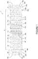
- Figure 1 is a top view of an embodiment of a panel (1) for use in the textile.
- Panel (1) can be manufactured to any width and length. However, for some applications, the distance (or panel length) between outer edges (26a) and (26b) can be between 0.5m and 1.0m while the distance (or panel width) along the outer edge (e.g. 26a, 26b) can be as large as required. For example, the panel width can be approximately equal to the required textile width.
- Panel (1) includes a body region (5) located in between first and second fold regions (61, 62).
- Each fold region (61, 62) includes an outer edge (26a, 26b), an inner edge (28a, 28b), a column of hem slots (45a, 45b) and hem loop strips (25a, 25b); and a hem fold line (27a, 27b) midway through the column of hem slots (45a, 45b) and hem loop strips (25a, 25b).
- hem slots (45a, 45b) and hem loop strips (25a, 25b) will be used to hem the fold regions (61, 62) of the panel (1).
- the body region (5) extends between first and second inner edges (28a, 28b).
- Body region (5) also includes first and second seam columns of seam slots (41a, 41b) and seam loop strips (21a, 21b), with a seam fold line (35a, 35b) midway between each seam column.
- First and second seam regions (31, 32) are defined by the respective seam slots (41a, 41b), seam loop strips (21a, 21b) and seam fold lines (35a, 35b).
- seam slots (41a, 41b) and seam loop strips (21a, 21b) will be used to define a seam between adjacent folded panels.
- Body region (5) can also be defined in terms of first and second end body regions (11a, 11b) and a central body region (11c).
- hatching has been used to depict the inner surface of central body region (11c); this hatching does not imply that the composition of (11c) differs from that of end body regions (11a, 11b).
- Each end body region (11a, 11b) extends between its respective inner edge (28a, 28b) and seam fold line (35a, 35b), while the central body region (11c) extends between the first and second seam fold lines (35a) and (35b).
- End body regions (11a, 11b) are generally equal in length (i.e.
- each end body region (11a, 11b) can approximately equal the length (i.e. the distance between seam fold lines (35a, 35b)) of the central body region (11c).
- Body region (5) includes a series of columns of protrusions (57), with a land channel (56) in between each column. Protrusions (57) within a column are separated by a land area (53). As shown in Figure 2A . Protrusions (57) protrude outward from the inner surface of the panel (1).
- the protrusions (57) can be embossed throughout leaving depressions on the outer surface of panel (1).
- Protrusions (58a, 58b) are proximate the inner edge (28a, 28b) of each fold region (61, 62).
- the columns of protrusions (57) across the length of panel (1) are staggered (in a 1-2-1-2... pattern), while in each fold region (61, 62), each hem slot (45a, 45b) is directly across a protrusion (58a, 58b) proximate the inner edge (28a, 28b).
- protrusions (57) are arranged in regular columns oriented parallel to the seam fold lines (35a, 35b), other spatial arrangements of the protrusions may be possible such as offset (in relation to one another).
- protrusions (57) may all have the same size and shape, although other embossing patterns and protrusion shapes, such as those disclosed in WO 2013/181748 , WO 2013/188964 , WO 2014/053055 or WO 2014153644 (all of which are incorporated by reference) may be used.
- Figure 2A illustrates a side view of the panel (1) of Figure 1 showing the first folding step of the panel (1).
- Figure 2B is a perspective view of Figure 2A .
- the protrusions (57) can be further slit on their lateral sides in a precision slitting process to form apertures (55), as shown in Figure 2A .
- Each protrusion (57) includes a surface (51) supported by side surfaces (52), with an aperture (55) on one or both lateral sides.
- the inner surface in body region (5) forms a continuous outwardly profiled surface with depressions on the outer surface thereof.
- Apertures (55) allow for movement of fluid and/or air from one panel surface through to the other surface in the folded panel, while also providing a passageway (across the width of the folded panel) that can receive a filamentary element to allow for mechanical securement of the central body region with (11c) with two opposite end body regions (11a, 11b). This feature is discussed further below.
- panel (1) is folded along each fold line (27a, 27b), such that each fold region (61, 62) is folded into a U-shape.
- Each outer edge (26a, 26b) (shown in Figure 1 ) is folded towards the inner surface of the panel (1), and is approximately above the respective inner edge (28a, 28b) (see Fig. 1 ).
- This folding process forms hem loops (25a, 25b) alternating with hem loop-receiving openings (45a, 45b).
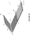
- FIGs 2C and 2D illustrate a subsequent folding of panel (1) after the initial folding step shown in Figures 2A and 2B .
- Panel (1) is folded along seam fold lines (35a, 35b), such that each end body region (11a, 11b) is folded toward central body region (11c).
- This folding step results in the formation of seam loops (21a, 21b) and seam loop-receiving openings (41a, 41b) at each end of panel (1) (note that only (21a) and (41a) are shown in Figure 2D ).
- end body region (11b) is being folded along the arc marked 'X', while end body region (11a) has been completely folded so that it is in contact with central body region (11c).
- Fold region (61) is nestled approximately at a midway point of central body region (11c), with hem loops (45a) receiving protrusions (57) from the central body region (11c).
- fold region (62) will be nestled approximately at a midway point of central body region (11c), with hem loops (45b) receiving protrusions (57) from the central body region (11c).
- Fold regions (61, 62) can be secured to the central body region (11c) in a manner described below.
- columns of protrusions from end body regions (11a, 11b) generally overlap in a staggered formation with columns of protrusions from the central body region (11c), such that the surface (51) of a protrusion (57) contacts an opposite land area (53). This is discussed in greater detail below.
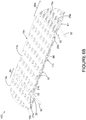
- FIG 3A illustrates the folded panel (10) once both end body regions (11a, 11b) are brought into contact with the central body region (11c), following the folding process illustrated in Figures 2A to 2D .
- Hem region (65) is defined as the overlap of fold regions (61, 62).
- end body regions (11a, 11b) form a first layer of folded panel (10)
- central body region (11c) forms a second layer of folded panel (10).
- the central body region (11c) may be oriented towards the product-conveying side of the industrial textile so that hem region (65) is oriented towards the machine.
- FIG. 3B illustrates in greater detail the hem region (65).
- Hem loop-receiving openings (45a, 45b) interconnect as follows. Hem loops (25a) of fold region (61) are inserted into hem loop-receiving openings (45b) of fold region (62), while hem loops (25b) of fold region (62) are inserted into hem loop-receiving openings (45a) of fold region (61). Furthermore, hem loop-receiving openings (45a, 45b) are dimensioned so as to receive protrusions (57) from central body region (11c).
- outer edges (26a, 26b) are aligned with protrusions (58a, 58b) so that surfaces of edge regions (85a, 85b) are located on the lower planar surface of land channel (56), and secured thereto (as discussed below).
- FIG 3C shows an enlargement of the seam region (31) at which adjacent panels may be joined.
- Seam region (31) includes a plurality of regularly spaced seam loops (21a) between which are located seam loop-receiving openings (41a).
- Seam loops (21a) and seam loop-receiving openings (41a) are formed by folding panel (1) at first seam fold line (35a) (shown in Figures 2C and 2D ), in the manner described above.
- seam channel (80) is formed via the seam loops (21a).
- FIG 4 is a side view of the folded panel (10) shown in Figures 3A to 3C .
- Hem region (65) includes interconnected fold regions (61, 62), such that hem channel (95) is formed by the overlap of hem loops (25a, 25b).
- a hem connecting member shown as (97) in Figures 6A and 6B ) may be inserted into hem channel (95) to secure the fold regions (61, 62) together.
- Seam regions (31, 32) include seam loops (21a, 21b).
- a seam channel (80) is formed within each set of seam loops (21a, 21b).
- edge regions (85a, 85b) can be secured to the inner surface of central body region (11c) at land channel (56), thereby configuring the folded panel (10) into a complete self-contained unit.
- the free ends (i.e. fold regions 61, 62) of the original panel (1) are contained within the first and second layers. That is, edge regions (85a, 85b) are shielded between the inner surfaces of end body regions (11a, 11b) and the inner surface of central body region (11c).
- Resistance to compression by the folded panel (10) can be enhanced by the optional insertion of a filamentary member (90), or similar material, through one or more aligned apertures (55) in the interior of folded panel (10).
- FIG. 5 is a top view of the folded panel (10) shown in Figure 4 , illustrating the insertion of hem loops (25a, 25b) into corresponding hem loop-receiving openings (45a, 45b). Furthermore, protrusions (57) from central body region (11c) are visible, as they are received by hem loop-receiving openings (45a, 45b).
- a hem channel (95) is formed allowing for receipt of a pintle or monofilament to further secure hem region (65).
- the interconnected hem loops (25a, 25b) can be secured in place using methods described below.
- Seam loops (21a, 21b) and seam loop-receiving openings (41a, 41b) are located at opposing ends of the folded panel (10), for interconnection with an adjacent folded panel, as described below.
- An industrial textile is constructed by interconnection of a series of adjacent folded panels by intermeshing the seam loops and seam loop receiving openings at the seam regions located at opposing ends of the folded panels. This is further illustrated in Figures 6A , 6B and 7 .
- the number of folded panels used to build the textile can vary according to the required textile length.
- Figure 6A provides a perspective view of a portion of a first embodiment of an industrial textile (100) constructed from a series of interconnecting folded panels (10a, 10b), in which the two interconnected panels (10a, 10b) are constructed as shown in Figures 3A to 3C .
- the direction of motion of the textile (100) is indicated by the arrow labeled MD, while the cross-machine direction (CD) is indicated as perpendicular to the MD.
- folded panels (10a, 10b) are interconnected at composite seam region (20), which includes seam loops from seam region (32) of folded panel (10a) interconnected with seam loops from seam region (33) of folded panel (10b) by a seam connecting member (82) (such as a pin, a pintle, a monofilament, or similar member known in the art).
- a seam connecting member (82) such as a pin, a pintle, a monofilament, or similar member known in the art.
- the hem regions (65a, 65b) of panels (10a, 10b) can be further secured by insertion of a hem connecting member (97) such as a monofilament or pin (or similar member known in the art) in the hem channel.
- a hem connecting member (97) such as a monofilament or pin (or similar member known in the art) in the hem channel.
- one or more hem connecting members (97) may be used; i.e. it is not necessary to secure all of the hem regions in the textile (100) with a connecting member (97). If a hem connecting member (97) is not used to secure a hem region (e.g. 65a, 65b), then such hem regions (65a, 65b) can be secured in a manner described in relation to Figure 8 .
- An enlarged view of composite seam region (20) and hem region (65a) of panel (10a) is provided in Figure 6B .
- the end body regions (11a, 11b, 12a, 12b) provide a surface that may face towards the machine on which the industrial textile is used; this surface is referred to as the "machine-side” (MS) surface.
- Central body regions (11c, 12c) may provide the product conveying side of the industrial textile; this surface is referred to as the "product-side” (PS) surface.
- MS machine-side
- PS product-side
- the distinction between the MS and PS is due to the location of the hem regions (65a, 65b). That is, the hem regions (65a, 65b) are on the MS.
- end body regions (11a, 11b) of folded panel (10a) are interconnected at hem region (65a) by means of a hem connecting member (97), such as a monofilament, which is inserted through the interdigitated hem loops (25a, 25b) of fold regions (61, 62).
- Protrusions (57) on the end and central body regions (11a, 11b, 11c) are oriented towards the interior of folded panel (10a), while the depressions are visible on the outer surfaces of each folded panel (10a, 10b).
- At least one lateral side of the protrusions (57) includes an aperture opening (55).
- folded panel (10a) protrusions (57) of end body regions (11a, 11b) are aligned with those of central body region (11c) such that the apertures (55) allow for movement of fluids, air and materials through the industrial textile (100).
- Folded panel (10b) is interconnected to folded panel (10a) by intermeshing of seam loops (21a, 21b) to provide a seam channel (not shown) through which seam connecting member (82) can be inserted.
- Multiple folded panels such as (10a) and (10b) may be interconnected in series in this manner so as to build up the length of the industrial textile (100) as required.
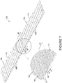
- Figure 7 is a perspective view showing the second surface of the two interconnected panels shown in Fig. 6A , and magnification of the interconnection region between the two folded panels, in which surface roughness has been applied to the outer surface of the central body regions (11c, 12c) of each folded panel (10a, 10b). That is, Figure 7 is a perspective view of what may be used as the product side (PS) surface of the industrial textile (100) as defined above.
- PS product side
- the hem regions (65a, 65b) are on the opposite machine side (MS) of the textile (100).
- protrusions (57) on the inner surface of the PS layer are aligned with, and engage with, corresponding protrusions (57) on the inner surface of the MS layer.
- a protrusion surface is secured to a corresponding planar land area of an opposing layer, as described in relation to Figure 8 .
- Seam loops from seam region (32) of panel (10a) are intermeshed with corresponding loop receiving openings in seam region (33) of panel (10b) forming seam channel (80) allowing for the interconnection of the two panels at composite seam region (20) by inserting a pin or pintle (such as (82) as described in Figure 6B ).
- the outer surface of the folded panels can have roughness thereon.
- An example of surface roughness is shown in the magnification of Figure 7 , where a portion of the outer surface of folded panels (10a, 10b) includes striations (48), as an example. Surface roughness is applied to reduce adherence of external contaminants. Other examples of surface roughness are described in US Patent No. 6,773,786 .
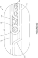
- Figure 8 is a side view of the hem region (65) of the folded panel (10) shown in Figure 4 , illustrating various internal construction features.
- Figure 8 is similar to Figure 4 and illustrates several possible securing methods in each of circled regions 8A through 8F that may be employed to secure the end and central body regions (11a, 11b, and 11c) forming the PS and MS layers of folded panel (10). These will each be discussed in turn.
- Figure 8A is an enlargement of circled area 8A in Figure 8 and illustrates the use of filamentary member (90), such as a monofilament or other yarn, inserted through aligned lateral apertures (55) of engaged protrusions (57) across the width of the interconnected folded panel (10).
- the filamentary member (90) mechanically interlocks the upper and lower panel layers through their aligned apertures (55) so as to prevent separation.
- This interconnection process may be repeated across the width and length of the textile at selected locations in order to reinforce the interconnection of the panel layers in the textile, and may be used either in place of, or in addition to, protrusion bonding locations such as (71a, 71b) shown in Figure 8B .
- Figure 8B is an enlargement of circled area 8B in Figure 8 illustrating one possible method of interconnecting the end fold regions (11a, 11b) with central body region (11c).
- Surface (51b) of protrusion (57b) located in end body region (11b) may be secured to the opposing planar area (53c) in central body region (11c), by means of a weld (71b) between these two surfaces.
- Welding can include, for example, through transmission laser welding (TTLW).
- TTLW transmission laser welding
- surface (51c) of protrusion (57c) located in central body region (11c) may be secured to opposing planar area (53b) by a weld at (71c).
- TTLW can be used as a securing method when the panel is formed from a thermoplastic, such as polyester.
- Other bonding methods including other welding methods (e.g.
- ultrasonic, vibrational, induction adhesives (such as chemical solvent adhesives, hot melt adhesives, epoxies and the like) or mechanical fasteners (e.g. inserts, snap-fits, swaging, staking) can be employed when the panel comprises a thermoset or a metal, since laser welding is not feasible in such cases.
- adhesives such as chemical solvent adhesives, hot melt adhesives, epoxies and the like
- mechanical fasteners e.g. inserts, snap-fits, swaging, staking
- Figure 8C illustrates the use of a spacer member (75) secured within fold region.
- Spacer member (75) can be placed in contact with edge region (85b) and an inner surface of the fold region, at contact points (e.g. 73b, 73c).
- One or more spacer members (75) can be used at selected edge regions and may be either continuous or discontinuous across the folded panel (10) width.
- Spacer member (75) can be formed from any suitable material, such as a material similar to, or substantially the same as that used to prepare the panels.
- the spacer member (75) may further comprise a laser weld enabling material, such as a polymeric monofilament, film or the like, which includes a suitable radiant energy absorber.
- the spacer member (75) should have a height that does not cause significant discontinuity in the otherwise planar surface of the folded panels.
- the width of the spacer member (75) should be such as to be accommodated by a land channel.
- the spacer member (75) can be bonded, for example, by laser welding at each of contact points (73b, 73c). Use of a spacer member (75) is optimal in the assembly of an industrial textile.
- Figure 8D illustrates a cross-sectional view of a hem region (65) including hem channel (95) with a hem connecting member (97) inserted therein.
- a hem connecting member (97) include a pin, a pintle, a monofilament or any other suitable material.
- a foam (67) such as an open cell porous foam or a closed cell foam can be inserted into the open spaces between end and central body regions (11a) and (11c). This can also occur in open spaces between end and central body regions (11b) and (11c).
- Foam (67) may provide additional compression resistance and enhance the strength of attachment between the folded panel (10) layers.
- porous nature of the open cell foam allows for the passage of fluids and/or air through the textile assembly; however, both an open or closed cell foam will further ensure both a strong bond between the opposing panel layers, and resistance to compressive forces that may be applied to the textile when in use.
- Figure 8E illustrates a portion of one edge region (85a) of panel (10) following interconnection at hem region (65). Edge region (85a) is secured at (74a) to land channel (56c) in central body region (11c). Securement may be formed by TTLW or other suitable means.
- Figure 8E also shows insertion of foam (67) (as described above) into the interior region between body regions (11a, 11c) proximate hem region (65). The foam (67) may be optionally injected into either the regions above land channel (56c), the apertures (55), into the exposed cavities of the folded panel (10), or any combination thereof prior to construction of the textile.
- Figure 8F illustrates the optional insertion of a foam (67) (as described above) injected into either the volume between land channels (not shown), apertures (55) remote from the hem region (shown in Figure 8E ), or into the exposed lower surfaces of central body region (11c), or any combination thereof, prior to construction of the textile.
- the interconnection of the panel layers may be optionally reinforced by securing top surfaces (51) of protrusions (57) to opposing planar area (53) as shown at (71a, 71c) in the manner previously described.
- FIG 9 illustrates an alternate arrangement of securing edge regions (85a, 85b) of the folded panel (10) arranged in the manner previously discussed.
- edge regions (85a, 85b) are secured at regions (74a) and (74b) to the inner surfaces of fold regions (61, 62), respectively. That is, each end fold region (61, 62) is no longer folded in a "U" shape (as in Figures 2 to 8 ), but rather, is arranged as a "rope hem” configuration.
- a portion (83a, 83b) of each end fold region (61, 62) is brought around hem channel (95) and is directed towards the inner surface of the fold regions (61, 62).
- Each edge region (85a, 85b) is in contact with the inner surface of the fold region (61, 62) where it is secured at (74a, 74b) in a manner described above.
- the embodiment presented in Figure 9 provides an alternate arrangement of the hem region in the construction and assembly of the textile. When a rope hem is used, securement of the end body regions (11a, 11b) with central body region (11c) can be achieved via one or more of the methods illustrated in Figs. 8A , 8B , 8D , and 8F .
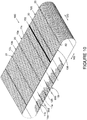
- Figure 10 is a perspective view of an embodiment of a double layer non-woven industrial textile (180) constructed from a plurality of folded panels such as (10a) and (10b) which are constructed and arranged as described above.
- a non-woven seaming element (150) can be used to join opposite ends of the assembled textile (180) to form a continuous belt that can be released by removal of seaming element (150).
- Folded panels are secured in series to form the textile (180) by interconnecting each of the multiple panels at their respective seam regions (for example at (31, 32, 33, 34) in Figure 6A ), as described above.
- Folded panels e.g., 10a, 10b
- hem regions e.g. (65a, 65b)
- the textile (180) is also defined by lateral edges (105, 106), which are common to all of the interconnected folded panels (e.g. (10a, 10b)).
- the folded panels (e.g., (10a, 10b)) can be secured from within by any of the methods described in relation to Figs. 8-8F and 9 . Furthermore, the upper surfaces of the central body regions of the folded panels (e.g. (10a, 10b)) can be provided with surface roughness, as shown, for example, in Figure 7 .
- folded panels such as (10a, 10b) are interconnected in the manner previously described as required to provide a given length of finished textile (180).
- Each folded panel is oriented so that its hem (e.g. 65a, 65b) and composite seam regions (e.g. 20) are transverse to the intended run direction, or MD, of the textile (180).
- the textile (180) is then cut in the CD within a central body region of the folded panels (e.g.
- the finished industrial textile (180) is thus a wholly non-woven double layer assembly that includes a seaming element (150) that allows for installation and removal of the textile (180).
- Figure 11 is a plan view of a surface of a second embodiment of a non-woven double-layer industrial textile (200) which may be used as the product side (PS). In this view, the hem regions are hidden below the PS surface. All of the folded panels (e.g. 10a, 10b, 1 10a, 110b) are constructed as described above, and interconnected at composite seam regions (20) across the MD as described above. In this embodiment of the textile (200), folded panels (e.g. 10a, 10b) are secured in the CD at their first (121a, 121b) and second (122a, 122b) lateral edges to folded panels (110a, 110b).
- folded panels e.g. 10a, 10b
- Securement across the lateral edges can be achieved, for example, by insertion of filamentary member (90) through aligned apertures (55) in the manner shown in Figure 8A .
- folded panels (10a, 10b) are referred to as “interior panels” while folded panels (110a, 110b) are referred to as “exterior panels”.
- adjacent interior panels (10a, 10b) are offset, so that their lateral edges (121a, 121b) and (122a, 122b) are discontinuous. This results in composite seam regions (20) that include a combination of interconnections between folded panels (10a) with (10b); (10b) with 110 (a), (110a) with (110b), and so on.
- Each exterior panel (110a, 110b) is structured and arranged to be identical with interior panels (10a, 10b). However, each of the exterior panels (110a, 110b) is made from a material different than that used in the composition of interior panels (10a, 10b).
- folded panels (10a, 10b) may be formed from a film comprised of polyethylene terephthalate (PET).
- PET polyethylene terephthalate
- the lateral edges of the textile (200) may be exposed to excess wear, heat and humidity, in which case, the PET may degrade (hydrolyze) more quickly than would be desirable.
- exterior panels (110a, 110b) that are made from heat- and hydrolysis-resistant materials, in the lateral regions of the textile (200) as shown in Figure 11 , it would be possible to prolong the service life of these exterior edges that are exposed to direct heat in the dryer section.
- heat-resistant and hydrolysis-resistant materials include polyphenylene sulfide (PPS) or polyaryletherketones such as PEEK.
- Figure 12 is a partial perspective view of the non-woven industrial textile shown in Figure 11 . Depressions visible in the outer surfaces of folded panels (10a, 10b) are formed by protrusions in the folded panels, as described previously.
- exterior panels (110a, 110b) may be attached in the following manner. Interior panels (10a, 10b) are interconnected in textile (200) such that lateral edges (121a, 121b) and (122a, 122b) are offset so that their lateral edges are staggered as shown in Figure 11 . Adjacent internal panels (10a, 10b) are secured to each other at composite seam regions (20), as previously described. A lateral edge of external panel (110a) is then aligned with lateral edge (121a) of one of the internal panels (10a). Since all of the folded panels are identical in structure, exterior panel (110a) is then interconnected to adjacent interior panels (10b) at seam regions (20) on either side of (110a).
- a seam connecting member (82) can be inserted in the seam channel (80) (e.g. as in Figure 7 ) formed in the composite seam regions (20) on either side of folded panels (10a) and (110a). This process is repeated for each exterior panel (110a, 110b) attached to the lateral edges (121a, 121b) of interior panels (10a, 10b) as well as at their opposite lateral edges (122a, 122b), if desired.
- a hem connecting member (97) can be inserted through the hem channel (95) at hem regions (e.g. 65a, 65b, 165a, 165b) of exterior panels (110a, 110b) and corresponding interior panels (10a, 10b) so as to further reinforce the folded panel interconnection in both the MD and CD.
- connection between exterior panels (110a, 110b) and corresponding interior panels (10a, 10b) in the CD can be further reinforced by inserting a filamentary element (90) through the aligned apertures of the folded panels in the manner described in relation to Figure 8A , so as to span at least a portion of the CD panel width.
- the outer lateral edges (115a, 115b) of exterior panels (110a, 110b) are then trimmed to remove any nonlinear variations.
- the edges (115a, 115b) can be sealed by heat, chemical or other suitable means to prevent migration of the filamentary member (90) from the aligned apertures.
- Panels used in the construction of a double-layer non-woven industrial textile can include a thermoplastic polymer material, such as (but not exclusively) polyesters, polyolefins and polyamides.
- the panel can include a thermoset polymer, such as (but not exclusively) polyimides.
- a formable metal may also be used in the construction of a panel.
- the panel is comprised of thermoplastics, laser welding can be used to secure panel surfaces and components to each other. Other bonding methods, such as chemical adhesives and mechanical attachments, can also be used.
- the panels can be formed from a film that comprises a medium to high intrinsic viscosity (IV) polyester selected from the group consisting of polyethylene terephthalate (PET), polybutylene terephthalate (PBT), polyethylene naphthalate (PEN), and poly(cyclohexylene dimethylene terephthalate) acid (PCTA).
- IV intrinsic viscosity
- PET polyethylene terephthalate
- PBT polybutylene terephthalate
- PEN polyethylene naphthalate
- PCTA poly(cyclohexylene dimethylene terephthalate) acid
- the panels can be made of polyphenylene sulphide (PPS), polyaryl ether ketones (PAEK) such as polyether ether ketones (PEEK), poly(cyclohexylene dimethylene terephthalate) acid (PCTA) or a hydrolysis-stabilized thermoplastic material.
- PPS polyphenylene sulphide
- PAEK polyaryl ether ketones
- PEEK polyether ether ketones
- PCTA poly(cyclohexylene dimethylene terephthalate) acid
- hydrolysis-stabilized thermoplastic material a hydrolysis-stabilized thermoplastic material.
- a film of polyester, in particular polyethylene terephthalate (PET), and having an IV that is between about 0.5 and 1.0 can be used.
- the film may be coextruded in two or more layers, or otherwise may consist of multiple layers.
- At least one layer of the PET film may also be biaxially oriented and hydrolytically stabilized to prevent premature depolymerization due to hydrolytic degradation when the film structure is intended for use in hot and moist environments.
- carbodiimides can be used. Examples of such films are disclosed in WO 2013/177670 (incorporated herein by reference) in which the film is oriented in both the longitudinal and transverse directions to maximize its elastic modulus and other physical properties, such as tensile strength and free shrinkage.
- the film, or at least one layer of a multilayer film comprises a hydrolytic stabilizer comprising a carbodiimide.
- the carbodiimide comprises between 0.5% parts by weight (w/w) and 5% w/w of the material of that layer.
- the carbodiimide can be selected from a monomeric form and a polymeric form. In particular the carbodiimide can be polymeric.
- the polymer film material used in the panel structures can also include a laser-weld enabling material; at least one film layer can comprise a radiant energy absorbent material such as carbon black.
- a polymeric film material is disclosed in WO 2013/071419 .
- the film material can comprise at least two coextruded miscible layers in which at least one outer layer includes a radiant energy absorbent material and is about from 5% to 20% of the overall film thickness or caliper, which may be from about 100 ⁇ m up to 500 ⁇ m.
- the overall film thickness can also be in the range of about 250 ⁇ m to 350 ⁇ m.
- a first layer can include a radiant energy absorbent material and can comprise from 5% to 15% of the overall film thickness, while the second layer can comprise from 85% to 95% of the overall film thickness.
- the first layer can comprises about 10% of the film thickness and the second layer can comprise about 90% of the film thickness.
- each outer layer can comprise from 5% to 20% of the overall film thickness and an inner layer can comprise from 60% to 90% of the total film thickness.
- each outer layer can comprise from 10% to 15% of the film thickness and the inner layer can comprise from 70% to 80% of the film thickness.
- At least one of the two outer layers can comprise a radiant energy absorbent material.
- the absorbent can be carbon black which is incorporated so as to comprise from about 0.1% w/w to about 1% w/w of the polymer material in the film layer.
- radiant energy absorbing materials such as clear or dyeable products e.g. Clearweld® (available from Gentex Corporation of Carbondale, PA) or Lumogen® (available from Basf Corporation) may also be used.
- the amounts of the additive used will depend on the additive selected, but where the additive is carbon black, it can be present in amounts ranging from about 0.1% w/w to about 1.0% w/w based on the total weight of the at least one outer film layer.
- the amount of laser energy absorbent material additive incorporated into the film layer depends on the final thickness of the layer, taking into account the wavelength of the laser intended to be used in the welding process.
- At least one layer of the multilayer film can further comprise an additive, such as at least one of titanium dioxide, or at least one dye.
- the panel may be constructed of a thermoset polymer material such as a commercially available linear or aromatic heterocyclic polyimides which are sold in the marketplace under the tradenames ApicalTM, KaptonTM, UPILEXTM, VTEC PITM, Norton THTM and KaptrexTM; others may be suitable.
- Thermosets are not amenable to laser welding and can be bonded using one of an epoxy, a solvent or chemical adhesive such as a hot melt adhesive.
- a formable metal material may also be employed and, in particular, a formable metal material selected from at least one of aluminum alloy, brass, cold rolled steel, copper, galvanized steel, high strength low alloy steel, hot rolled steel, steel alloys, stainless steel and zinc.
- a formable metal material refers to a metal that that can undergo strain beyond the elastic limit of the material without causing excessive strain localization or fracture. Panels formed from these metals are amenable to both laser and resistance welding and can be bonded by these or similar means.
- a formable metal material may also be employed and, in particular, a formable metal material selected from at least one of aluminum alloy, brass, cold rolled steel, copper, galvanized steel, high strength low alloy steel, hot rolled steel, steel alloys, stainless steel and zinc.
- a formable metal material refers to a metal that that can undergo strain beyond the elastic limit of the material without causing excessive strain localization or fracture. Panels formed from these metals are amenable to both laser and resistance welding and can be bonded by these or similar means.
Landscapes
- Engineering & Computer Science (AREA)
- General Engineering & Computer Science (AREA)
- Mechanical Engineering (AREA)
- Textile Engineering (AREA)
- Treatment Of Fiber Materials (AREA)
- Laminated Bodies (AREA)
- Tents Or Canopies (AREA)
Claims (15)
- Panneau (1) destiné à être utilisé dans la fabrication d'un textile industriel non tissé (180), le panneau (1) comprenant :a) une surface intérieure et une surface extérieure ;b) deux bords latéraux (105, 106) opposés et deux bords extérieurs (26a, 26b) opposés ;c) une première et une seconde zone de pliage (61, 62) à chaque extrémité du panneau (1), chaque zone de pliage comprenant :i) un bord extérieur (26a, 26b) du panneau (1) ;ii) une zone de bord (85a, 85b) ;iii) une colonne de bandes de boucle d'ourlet (25a, 25b) et de fentes d'ourlet (45a, 45b), la colonne étant orientée parallèlement au bord extérieur (26a, 26b) et placée adjacente à la zone de bord (85a, 85b) ; etiv) une ligne de pliage d'ourlet (27a, 27b) sensiblement au milieu de la colonne de bandes de boucle d'ourlet (25a, 25b) et de fentes d'ourlet (45a, 45b), la ligne de pliage d'ourlet (27a, 27b) étant orientée parallèlement au bord extérieur (26a, 26b) ;d) une zone de corps (5) entre la première et la seconde zone de pliage (61, 62), la zone de corps (5) comprenant :le panneau (1) forme un panneau (1) plié quand le panneau (1) est :i) une pluralité de saillies (57) et d'espaces plats (53) sur la surface intérieure du panneau (1), avec un espace plat (53) entre chaque saillie (57) ;ii) une première et une seconde zone de jonction (31, 32), chaque zone de jonction (31, 32) comprenant : une colonne de fentes de jonction (41a, 41b) et de bandes de boucle de jonction (21a, 21b), la colonne étant orientée parallèlement au bord extérieur (26a, 26b) ; et une ligne de pliage de jonction (35a, 35b) sensiblement au milieu de la colonne de bandes de boucle de jonction (21a, 21b) et de fentes de jonction (41a, 41b), orientée parallèlement au bord extérieur (26a, 26b) ;iii) une première et une seconde zone de corps d'extrémité (11a, 11b), la première zone de corps d'extrémité (11a) étant entre la première zone de pliage (61) et la première ligne de pliage de jonction (35a) ;
la seconde zone de corps d'extrémité (11b) étant entre la seconde zone de pliage (62) et la seconde ligne de pliage de jonction (35b) ; etiv) une zone de corps centrale (11c) entre la première et la seconde ligne de pliage de jonction (35a, 35b) ; dans lequeld'abord plié le long de chaque ligne de pliage d'ourlet (27a, 27b) de sorte que chaque bord extérieur (26a, 26b) est orienté vers la surface intérieure du panneau (1), chaque bande de boucle d'ourlet (25a, 25b) forme une boucle d'ourlet (25a, 25b), et chaque fente d'ourlet (45a, 45b) forme une ouverture de réception de boucle d'ourlet (45a, 45b) pour recevoir une boucle d'ourlet (25a, 25b) de la zone de pliage opposée ;puis plié le long de chaque ligne de pliage de jonction (35a, 35b) de sorte que la surface intérieure du panneau (1) sur chaque zone de corps d'extrémité (11a, 11b) est orientée opposée à la surface intérieure du panneau (1) sur la zone de corps centrale (11c) ; la première et la seconde zones de pliage (61, 62) sont reliées entre elles sur une zone d'ourlet (65) et nichées entre la zone de corps centrale (11c) et les zones de corps d'extrémité (11a, 11b) respectives ; chaque bande de boucle de jonction (21a, 21b) forme une boucle de jonction (21a, 21b) ; chaque fente de jonction (41a, 41b) forme une ouverture de réception de boucle de jonction (41a, 41b) pour recevoir une boucle de jonction (21a, 21b) d'un panneau (10) plié adjacent ; les zones de corps d'extrémité (11a, 11b) combinées forment une première couche du panneau plié, la zone de corps centrale (11c) forme une seconde couche du panneau (10) plié ; et la première couche est fixée à la seconde couche en fixant des saillies (57) de la première couche à des espaces plats (53) opposés de la seconde couche et/ou en fixant des saillies (57) de la seconde couche à des espaces plats (53) opposés de la première couche. - Panneau (1) selon la revendication 1, dans lequel
la pluralité de saillies (57) est agencée en une série de colonnes parallèles à chaque colonne de bandes de boucle de jonction (21a, 21b) et de fentes de jonction (41a, 41b). - Panneau (1) selon l'une quelconque des revendications 1 à 2, dans lequel chaque saillie (57) comprend au moins un orifice latéral (55).
- Panneau (1) selon la revendication 3, dans lequel
l'au moins un orifice (55) latéral fournit un chemin d'écoulement pour qu'un fluide et/ou de l'air passe entre la surface extérieure et la surface intérieure du panneau (1). - Panneau (1) selon l'une quelconque des revendications 1 à 4, dans lequel dans le panneau (10) plié, chaque zone de pliage (61, 62) est pliée en forme de U, et les zones de pliage (61, 62) sont fixées ensemble par :a) un élément de liaison d'ourlet (97) placé dans un canal d'ourlet (95) formé par les zones de pliage (61, 62) reliées entre elles ; et/oub) le fait que chaque zone de bord (85a, 85b) est fixée à la surface intérieure de la zone de corps d'extrémité (11a, 11b) opposée.
- Panneau (1) selon l'une quelconque des revendications 1 à 5, comprenant un matériau thermoplastique, un matériau thermodurcissable ou un métal malléable.
- Textile industriel non tissé à double couche (180) constitué d'une pluralité de panneaux (10a, 10b) pliés fixés de manière adjacente en série, dans lequel :a) chaque panneau (10a, 10b) plié est formé selon la revendication 1 ;b) des panneaux (10a, 10b) pliés adjacents sont reliés entre eux sur une zone de jonction (20) composée, la zone de jonction (20) composée étant formée par l'insertion des boucles de jonction (21a) d'un premier panneau (10a) plié dans les ouvertures de réception de boucle de jonction (41b) d'un second panneau (10b) plié et les boucles de jonction (21b) du second panneau (10b) plié dans les ouvertures de réception de boucle de jonction (41a) du premier panneau (10a) plié, formant ainsi un canal de jonction (80) sur la zone de jonction (20) composée ; etc) les panneaux (10, 10b) pliés adjacents sont fixés l'un à l'autre par l'insertion d'un élément de liaison de jonction (82) dans le canal de jonction (80) entre les panneaux (10a, 10b) pliés adjacents.
- Textile industriel non tissé à double couche (180) selon la revendication 7, dans lequel
dans chaque panneau (10a, 10b) plié, la pluralité de saillies (57) est agencée en une série de colonnes parallèles à chaque colonne de bandes de boucle de jonction (21a, 21b) et de fentes de jonction (41a, 41b). - Textile industriel non tissé à double couche (180) selon la revendication 7 ou 8, dans lequel
chaque saillie (57) comprend au moins un orifice latéral (55). - Textile industriel non tissé à double couche (180) selon la revendication 9, dans lequel
la zone de corps centrale (11c) et les zones de corps d'extrémité (11a, 11b) d'au moins un panneau (10a, 10b) plié sont en outre fixées ensemble par au moins un élément filamentaire (90) qui passe à travers des orifices (55) alignés d'une colonne de saillies (57) de la première couche en quinconce avec une colonne de saillies (57) de la seconde couche. - Textile industriel non tissé à double couche (180) selon l'une quelconque des revendications 7 à 10, dans lequel
dans chaque panneau (10a, 10b) plié, chaque zone de pliage (61, 62) est pliée en forme de U, et les zones de pliage (61, 62) sont fixées ensemble par :a) un élément de liaison d'ourlet (97) placé dans un canal d'ourlet (95) formé par les zones de pliage (61, 62) reliées entre elles ; et/oub) le fait que chaque zone de bord (85a, 85b) est fixée à la surface intérieure de la zone de corps d'extrémité (11a, 11b) opposée. - Textile industriel non tissé à double couche (180) selon l'une quelconque des revendications 7 à 11, dans lequel
chaque panneau (10a, 10b) plié comprend un matériau thermoplastique, un matériau thermodurcissable ou un métal malléable. - Panneau (1) selon la revendication 3, comprenant en outre :a) au moins une couche de film polymère en PET orienté qui comprend un matériau absorbant l'énergie de rayonnement.
- Panneau (1) selon la revendication 13, dans lequel
le film polymère est à orientation biaxiale. - Panneau (1) selon l'une quelconque des revendications 13 et 14, dans lequel le panneau comprend au moins deux couches coextrudées de film polymère, et une des au moins deux couches coextrudées comprend un matériau absorbant l'énergie de rayonnement.
Applications Claiming Priority (2)
| Application Number | Priority Date | Filing Date | Title |
|---|---|---|---|
| CA2835951 | 2013-12-06 | ||
| PCT/CA2014/000864 WO2015081417A1 (fr) | 2013-12-06 | 2014-12-05 | Textile industriel à double couche non tissé assemblé à partir de panneaux configurés en manchon, et panneaux associés |
Publications (3)
| Publication Number | Publication Date |
|---|---|
| EP3077593A1 EP3077593A1 (fr) | 2016-10-12 |
| EP3077593A4 EP3077593A4 (fr) | 2017-11-08 |
| EP3077593B1 true EP3077593B1 (fr) | 2018-11-14 |
Family
ID=53272675
Family Applications (2)
| Application Number | Title | Priority Date | Filing Date |
|---|---|---|---|
| EP14867496.3A Active EP3077594B1 (fr) | 2013-12-06 | 2014-12-05 | Textile industriel à double couche non tissé assemblé à partir de panneaux plissés |
| EP14867109.2A Active EP3077593B1 (fr) | 2013-12-06 | 2014-12-05 | Textile industriel à double couche non tissé assemblé à partir de panneaux configurés en manchon, et panneaux associés |
Family Applications Before (1)
| Application Number | Title | Priority Date | Filing Date |
|---|---|---|---|
| EP14867496.3A Active EP3077594B1 (fr) | 2013-12-06 | 2014-12-05 | Textile industriel à double couche non tissé assemblé à partir de panneaux plissés |
Country Status (4)
| Country | Link |
|---|---|
| US (2) | US9593450B2 (fr) |
| EP (2) | EP3077594B1 (fr) |
| CN (2) | CN105793491B (fr) |
| WO (2) | WO2015081418A1 (fr) |
Families Citing this family (12)
| Publication number | Priority date | Publication date | Assignee | Title |
|---|---|---|---|---|
| CN105951497A (zh) * | 2015-09-14 | 2016-09-21 | 安徽华宇网业有限公司 | 一种耐磨扁丝干网 |
| US10005614B2 (en) * | 2016-02-25 | 2018-06-26 | Hemlock Semiconductor Operations Llc | Surface conditioning of conveyor materials or contact surfaces |
| CN106283819B (zh) * | 2016-08-24 | 2018-02-16 | 四川环龙技术织物有限公司 | 一种基于互锁连接关系的无纺工业织物 |
| CN106245404B (zh) * | 2016-08-24 | 2018-02-16 | 四川环龙技术织物有限公司 | 一种造纸机网用布基底织物连接接缝区域制备工艺 |
| AU2017344759B2 (en) * | 2016-10-20 | 2022-10-06 | Combitile Pty Ltd | A ground covering for outdoor application |
| CN110366616B (zh) * | 2017-02-28 | 2022-01-04 | 东丽株式会社 | 层叠不织布及面膜 |
| DE102017114964A1 (de) * | 2017-07-05 | 2019-01-10 | Voith Patent Gmbh | Bespannung und Herstellverfahren für eine solche Bespannung |
| WO2020076534A1 (fr) | 2018-10-10 | 2020-04-16 | Astenjohnson, Inc. | Outil d'insertion d'aiguille |
| DE102019121485B3 (de) * | 2019-08-09 | 2020-08-06 | Voith Patent Gmbh | Bespannung |
| DE102020113073A1 (de) | 2020-05-14 | 2021-11-18 | Voith Patent Gmbh | Bespannung und Herstellverfahren für eine solche Bespannung |
| USD1015524S1 (en) * | 2021-04-21 | 2024-02-20 | Jiabing Tang | Air vent plate for car window |
| CN114474884A (zh) * | 2022-03-21 | 2022-05-13 | 芜湖市精准传动系统研究院 | 一种帘布结构的采棉机打包带 |
Family Cites Families (25)
| Publication number | Priority date | Publication date | Assignee | Title |
|---|---|---|---|---|
| US2005979A (en) * | 1934-07-14 | 1935-06-25 | Ayers Ltd | Drier felt for paper making machines |
| US3162567A (en) * | 1961-05-18 | 1964-12-22 | Kimberly Clark Co | Papermaking machine forming member |
| US3323226A (en) * | 1963-05-28 | 1967-06-06 | Huyck Corp | Synthetic dryer belt |
| US3368933A (en) | 1963-11-15 | 1968-02-13 | Huyck Corp | Corrugator combiner machine |
| US3309790A (en) | 1964-08-21 | 1967-03-21 | Fabric Res Lab Inc | Light-weight dryer felt seams |
| US3324991A (en) * | 1965-08-18 | 1967-06-13 | Voss Belting & Specialty Co | Conveyor belts |
| US3530898A (en) * | 1968-10-30 | 1970-09-29 | Raychem Corp | Closure sleeve |
| US4911683A (en) * | 1988-08-03 | 1990-03-27 | The Draper Felt Company, Inc. | Seam for work fabric and method of manufacture thereof |
| JP2000044026A (ja) * | 1998-07-30 | 2000-02-15 | Nitta Ind Corp | コンベアベルト |
| GB0325463D0 (en) * | 2003-10-31 | 2003-12-03 | Voith Fabrics Patent Gmbh | Three dimensional tomographic fabric assembly |
| DE102004044568B4 (de) * | 2004-09-15 | 2021-08-05 | Voith Patent Gmbh | Pressstoffe |
| GB2432337A (en) * | 2005-11-22 | 2007-05-23 | Marc Pierre Despault | Offset intermeshing industrial fabric seam |
| BRPI0816197B1 (pt) * | 2007-09-05 | 2018-12-18 | Albany Int Corp | método de solda de parte de tecido industrial e costura. |
| DE102008000123A1 (de) * | 2008-01-22 | 2009-07-23 | Voith Patent Gmbh | Papiermaschinenbespannung mit Scharniernaht |
| GB2469651A (en) * | 2009-04-21 | 2010-10-27 | Allan Richard Manninen | Seaming device for an industrial fabric |
| CA2688470A1 (fr) * | 2009-12-11 | 2011-06-11 | Allan Manninen | Tissu industriel fait d'une pellicule gaufree munie de fentes selectives |
| CA2688168A1 (fr) * | 2009-12-11 | 2011-06-11 | Richard Stone | Element de couture du type a charniere pour joindre les bouts d'un textile industriel |
| CA2696648A1 (fr) * | 2010-03-09 | 2011-09-09 | Scott Makepeace | Monofilaments en polyester comportant du disulfure de molybdene et textiles industriels produits au moyen ce ceux-ci |
| CA2749477A1 (fr) * | 2011-08-18 | 2013-02-18 | Allan R. MANNINEN | Element de couture profile pour textiles industriels |
| CA2758622A1 (fr) * | 2011-11-17 | 2013-05-17 | Allan R. MANNINEN | Film ou filament polymere coextrude par soudage au laser et tissus fabriques a l'aide de la methode |
| CA2779131A1 (fr) * | 2012-06-07 | 2013-12-07 | Allan R. MANNINEN | Pellicules gaufrees munies de fentes selectives et resistantes a la compression et textiles industriels composes de celles-ci |
| CA2779969A1 (fr) * | 2012-06-18 | 2013-12-18 | Allan R. MANNINEN | Textiles non tisses resistants au cisaillement en ligne comportant une pellicule selectivement fendue et gaufree |
| CA2791864A1 (fr) * | 2012-10-04 | 2014-04-04 | Allan R. MANNINEN | Structures de film pour textile industriel non tisse autobloquant |
| CA2795208A1 (fr) * | 2012-11-13 | 2014-05-13 | Allan R. MANNINEN | Element de couture pour textiles industriels et procede de fabrication |
| CN105247135B (zh) * | 2013-03-26 | 2018-04-10 | 阿斯顿约翰逊公司 | 机械互锁的无纺工业织物 |
-
2014
- 2014-12-05 CN CN201480066473.XA patent/CN105793491B/zh active Active
- 2014-12-05 CN CN201480056377.7A patent/CN105637145B/zh active Active
- 2014-12-05 EP EP14867496.3A patent/EP3077594B1/fr active Active
- 2014-12-05 WO PCT/CA2014/000866 patent/WO2015081418A1/fr not_active Ceased
- 2014-12-05 US US15/101,807 patent/US9593450B2/en active Active
- 2014-12-05 EP EP14867109.2A patent/EP3077593B1/fr active Active
- 2014-12-05 WO PCT/CA2014/000864 patent/WO2015081417A1/fr not_active Ceased
- 2014-12-05 US US15/101,729 patent/US9587351B2/en active Active
Non-Patent Citations (1)
| Title |
|---|
| None * |
Also Published As
| Publication number | Publication date |
|---|---|
| WO2015081418A1 (fr) | 2015-06-11 |
| CN105637145A (zh) | 2016-06-01 |
| US20160312406A1 (en) | 2016-10-27 |
| EP3077593A1 (fr) | 2016-10-12 |
| EP3077593A4 (fr) | 2017-11-08 |
| CN105793491A (zh) | 2016-07-20 |
| US20160305069A1 (en) | 2016-10-20 |
| EP3077594B1 (fr) | 2019-01-30 |
| WO2015081417A1 (fr) | 2015-06-11 |
| CN105793491B (zh) | 2018-02-02 |
| EP3077594A4 (fr) | 2017-12-27 |
| EP3077594A1 (fr) | 2016-10-12 |
| US9587351B2 (en) | 2017-03-07 |
| CN105637145B (zh) | 2018-04-10 |
| US9593450B2 (en) | 2017-03-14 |
Similar Documents
| Publication | Publication Date | Title |
|---|---|---|
| EP3077593B1 (fr) | Textile industriel à double couche non tissé assemblé à partir de panneaux configurés en manchon, et panneaux associés | |
| US8563114B2 (en) | Industrial fabric comprised of selectively slit and embossed film | |
| US9487911B2 (en) | Profiled seaming element for industrial textiles | |
| US10155342B2 (en) | Seam for an industrial fabric and seaming element therefor | |
| CA2758622A1 (fr) | Film ou filament polymere coextrude par soudage au laser et tissus fabriques a l'aide de la methode | |
| CN105247135B (zh) | 机械互锁的无纺工业织物 | |
| EP2861417B1 (fr) | Materiaux résistants au cisaillement en ligne constitués d'un film sélectivement coupé et gaufré | |
| US9598814B2 (en) | Double pin seaming element |
Legal Events
| Date | Code | Title | Description |
|---|---|---|---|
| PUAI | Public reference made under article 153(3) epc to a published international application that has entered the european phase |
Free format text: ORIGINAL CODE: 0009012 |
|
| 17P | Request for examination filed |
Effective date: 20160705 |
|
| AK | Designated contracting states |
Kind code of ref document: A1 Designated state(s): AL AT BE BG CH CY CZ DE DK EE ES FI FR GB GR HR HU IE IS IT LI LT LU LV MC MK MT NL NO PL PT RO RS SE SI SK SM TR |
|
| AX | Request for extension of the european patent |
Extension state: BA ME |
|
| DAX | Request for extension of the european patent (deleted) | ||
| A4 | Supplementary search report drawn up and despatched |
Effective date: 20171010 |
|
| RIC1 | Information provided on ipc code assigned before grant |
Ipc: D21F 7/08 20060101ALI20171004BHEP Ipc: D21F 1/00 20060101ALI20171004BHEP Ipc: B32B 3/26 20060101ALI20171004BHEP Ipc: D21F 1/10 20060101AFI20171004BHEP Ipc: D04H 13/00 20060101ALI20171004BHEP Ipc: B65G 15/30 20060101ALI20171004BHEP Ipc: F16G 3/02 20060101ALI20171004BHEP |
|
| REG | Reference to a national code |
Ref country code: DE Ref legal event code: R079 Ref document number: 602014036244 Country of ref document: DE Free format text: PREVIOUS MAIN CLASS: D21F0001100000 Ipc: D21F0007100000 |
|
| GRAP | Despatch of communication of intention to grant a patent |
Free format text: ORIGINAL CODE: EPIDOSNIGR1 |
|
| RIC1 | Information provided on ipc code assigned before grant |
Ipc: D21F 7/08 20060101ALI20180604BHEP Ipc: F16G 3/04 20060101ALI20180604BHEP Ipc: D21F 1/00 20060101ALI20180604BHEP Ipc: D21F 7/10 20060101AFI20180604BHEP |
|
| INTG | Intention to grant announced |
Effective date: 20180621 |
|
| GRAS | Grant fee paid |
Free format text: ORIGINAL CODE: EPIDOSNIGR3 |
|
| GRAA | (expected) grant |
Free format text: ORIGINAL CODE: 0009210 |
|
| AK | Designated contracting states |
Kind code of ref document: B1 Designated state(s): AL AT BE BG CH CY CZ DE DK EE ES FI FR GB GR HR HU IE IS IT LI LT LU LV MC MK MT NL NO PL PT RO RS SE SI SK SM TR |
|
| REG | Reference to a national code |
Ref country code: CH Ref legal event code: EP Ref country code: AT Ref legal event code: REF Ref document number: 1064962 Country of ref document: AT Kind code of ref document: T Effective date: 20181115 |
|
| REG | Reference to a national code |
Ref country code: IE Ref legal event code: FG4D |
|
| REG | Reference to a national code |
Ref country code: DE Ref legal event code: R096 Ref document number: 602014036244 Country of ref document: DE |
|
| REG | Reference to a national code |
Ref country code: NL Ref legal event code: MP Effective date: 20181114 |
|
| REG | Reference to a national code |
Ref country code: LT Ref legal event code: MG4D |
|
| REG | Reference to a national code |
Ref country code: AT Ref legal event code: MK05 Ref document number: 1064962 Country of ref document: AT Kind code of ref document: T Effective date: 20181114 |
|
| PG25 | Lapsed in a contracting state [announced via postgrant information from national office to epo] |
Ref country code: BG Free format text: LAPSE BECAUSE OF FAILURE TO SUBMIT A TRANSLATION OF THE DESCRIPTION OR TO PAY THE FEE WITHIN THE PRESCRIBED TIME-LIMIT Effective date: 20190214 Ref country code: NO Free format text: LAPSE BECAUSE OF FAILURE TO SUBMIT A TRANSLATION OF THE DESCRIPTION OR TO PAY THE FEE WITHIN THE PRESCRIBED TIME-LIMIT Effective date: 20190214 Ref country code: LT Free format text: LAPSE BECAUSE OF FAILURE TO SUBMIT A TRANSLATION OF THE DESCRIPTION OR TO PAY THE FEE WITHIN THE PRESCRIBED TIME-LIMIT Effective date: 20181114 Ref country code: LV Free format text: LAPSE BECAUSE OF FAILURE TO SUBMIT A TRANSLATION OF THE DESCRIPTION OR TO PAY THE FEE WITHIN THE PRESCRIBED TIME-LIMIT Effective date: 20181114 Ref country code: HR Free format text: LAPSE BECAUSE OF FAILURE TO SUBMIT A TRANSLATION OF THE DESCRIPTION OR TO PAY THE FEE WITHIN THE PRESCRIBED TIME-LIMIT Effective date: 20181114 Ref country code: ES Free format text: LAPSE BECAUSE OF FAILURE TO SUBMIT A TRANSLATION OF THE DESCRIPTION OR TO PAY THE FEE WITHIN THE PRESCRIBED TIME-LIMIT Effective date: 20181114 Ref country code: AT Free format text: LAPSE BECAUSE OF FAILURE TO SUBMIT A TRANSLATION OF THE DESCRIPTION OR TO PAY THE FEE WITHIN THE PRESCRIBED TIME-LIMIT Effective date: 20181114 Ref country code: IS Free format text: LAPSE BECAUSE OF FAILURE TO SUBMIT A TRANSLATION OF THE DESCRIPTION OR TO PAY THE FEE WITHIN THE PRESCRIBED TIME-LIMIT Effective date: 20190314 |
|
| PG25 | Lapsed in a contracting state [announced via postgrant information from national office to epo] |
Ref country code: PT Free format text: LAPSE BECAUSE OF FAILURE TO SUBMIT A TRANSLATION OF THE DESCRIPTION OR TO PAY THE FEE WITHIN THE PRESCRIBED TIME-LIMIT Effective date: 20190314 Ref country code: GR Free format text: LAPSE BECAUSE OF FAILURE TO SUBMIT A TRANSLATION OF THE DESCRIPTION OR TO PAY THE FEE WITHIN THE PRESCRIBED TIME-LIMIT Effective date: 20190215 Ref country code: NL Free format text: LAPSE BECAUSE OF FAILURE TO SUBMIT A TRANSLATION OF THE DESCRIPTION OR TO PAY THE FEE WITHIN THE PRESCRIBED TIME-LIMIT Effective date: 20181114 Ref country code: SE Free format text: LAPSE BECAUSE OF FAILURE TO SUBMIT A TRANSLATION OF THE DESCRIPTION OR TO PAY THE FEE WITHIN THE PRESCRIBED TIME-LIMIT Effective date: 20181114 Ref country code: RS Free format text: LAPSE BECAUSE OF FAILURE TO SUBMIT A TRANSLATION OF THE DESCRIPTION OR TO PAY THE FEE WITHIN THE PRESCRIBED TIME-LIMIT Effective date: 20181114 Ref country code: AL Free format text: LAPSE BECAUSE OF FAILURE TO SUBMIT A TRANSLATION OF THE DESCRIPTION OR TO PAY THE FEE WITHIN THE PRESCRIBED TIME-LIMIT Effective date: 20181114 |
|
| PG25 | Lapsed in a contracting state [announced via postgrant information from national office to epo] |
Ref country code: CZ Free format text: LAPSE BECAUSE OF FAILURE TO SUBMIT A TRANSLATION OF THE DESCRIPTION OR TO PAY THE FEE WITHIN THE PRESCRIBED TIME-LIMIT Effective date: 20181114 Ref country code: DK Free format text: LAPSE BECAUSE OF FAILURE TO SUBMIT A TRANSLATION OF THE DESCRIPTION OR TO PAY THE FEE WITHIN THE PRESCRIBED TIME-LIMIT Effective date: 20181114 Ref country code: IT Free format text: LAPSE BECAUSE OF FAILURE TO SUBMIT A TRANSLATION OF THE DESCRIPTION OR TO PAY THE FEE WITHIN THE PRESCRIBED TIME-LIMIT Effective date: 20181114 Ref country code: PL Free format text: LAPSE BECAUSE OF FAILURE TO SUBMIT A TRANSLATION OF THE DESCRIPTION OR TO PAY THE FEE WITHIN THE PRESCRIBED TIME-LIMIT Effective date: 20181114 |
|
| REG | Reference to a national code |
Ref country code: CH Ref legal event code: PL |
|
| REG | Reference to a national code |
Ref country code: DE Ref legal event code: R097 Ref document number: 602014036244 Country of ref document: DE |
|
| PG25 | Lapsed in a contracting state [announced via postgrant information from national office to epo] |
Ref country code: SK Free format text: LAPSE BECAUSE OF FAILURE TO SUBMIT A TRANSLATION OF THE DESCRIPTION OR TO PAY THE FEE WITHIN THE PRESCRIBED TIME-LIMIT Effective date: 20181114 Ref country code: MC Free format text: LAPSE BECAUSE OF FAILURE TO SUBMIT A TRANSLATION OF THE DESCRIPTION OR TO PAY THE FEE WITHIN THE PRESCRIBED TIME-LIMIT Effective date: 20181114 Ref country code: SM Free format text: LAPSE BECAUSE OF FAILURE TO SUBMIT A TRANSLATION OF THE DESCRIPTION OR TO PAY THE FEE WITHIN THE PRESCRIBED TIME-LIMIT Effective date: 20181114 Ref country code: LU Free format text: LAPSE BECAUSE OF NON-PAYMENT OF DUE FEES Effective date: 20181205 Ref country code: EE Free format text: LAPSE BECAUSE OF FAILURE TO SUBMIT A TRANSLATION OF THE DESCRIPTION OR TO PAY THE FEE WITHIN THE PRESCRIBED TIME-LIMIT Effective date: 20181114 Ref country code: RO Free format text: LAPSE BECAUSE OF FAILURE TO SUBMIT A TRANSLATION OF THE DESCRIPTION OR TO PAY THE FEE WITHIN THE PRESCRIBED TIME-LIMIT Effective date: 20181114 |
|
| REG | Reference to a national code |
Ref country code: IE Ref legal event code: MM4A |
|
| PLBE | No opposition filed within time limit |
Free format text: ORIGINAL CODE: 0009261 |
|
| STAA | Information on the status of an ep patent application or granted ep patent |
Free format text: STATUS: NO OPPOSITION FILED WITHIN TIME LIMIT |
|
| REG | Reference to a national code |
Ref country code: BE Ref legal event code: MM Effective date: 20181231 |
|
| 26N | No opposition filed |
Effective date: 20190815 |
|
| GBPC | Gb: european patent ceased through non-payment of renewal fee |
Effective date: 20190214 |
|
| PG25 | Lapsed in a contracting state [announced via postgrant information from national office to epo] |
Ref country code: FR Free format text: LAPSE BECAUSE OF NON-PAYMENT OF DUE FEES Effective date: 20190114 Ref country code: IE Free format text: LAPSE BECAUSE OF NON-PAYMENT OF DUE FEES Effective date: 20181205 Ref country code: SI Free format text: LAPSE BECAUSE OF FAILURE TO SUBMIT A TRANSLATION OF THE DESCRIPTION OR TO PAY THE FEE WITHIN THE PRESCRIBED TIME-LIMIT Effective date: 20181114 |
|
| PG25 | Lapsed in a contracting state [announced via postgrant information from national office to epo] |
Ref country code: BE Free format text: LAPSE BECAUSE OF NON-PAYMENT OF DUE FEES Effective date: 20181231 |
|
| PG25 | Lapsed in a contracting state [announced via postgrant information from national office to epo] |
Ref country code: LI Free format text: LAPSE BECAUSE OF NON-PAYMENT OF DUE FEES Effective date: 20181231 Ref country code: CH Free format text: LAPSE BECAUSE OF NON-PAYMENT OF DUE FEES Effective date: 20181231 |
|
| PG25 | Lapsed in a contracting state [announced via postgrant information from national office to epo] |
Ref country code: MT Free format text: LAPSE BECAUSE OF NON-PAYMENT OF DUE FEES Effective date: 20181205 Ref country code: GB Free format text: LAPSE BECAUSE OF NON-PAYMENT OF DUE FEES Effective date: 20190214 |
|
| PG25 | Lapsed in a contracting state [announced via postgrant information from national office to epo] |
Ref country code: TR Free format text: LAPSE BECAUSE OF FAILURE TO SUBMIT A TRANSLATION OF THE DESCRIPTION OR TO PAY THE FEE WITHIN THE PRESCRIBED TIME-LIMIT Effective date: 20181114 |
|
| PG25 | Lapsed in a contracting state [announced via postgrant information from national office to epo] |
Ref country code: CY Free format text: LAPSE BECAUSE OF FAILURE TO SUBMIT A TRANSLATION OF THE DESCRIPTION OR TO PAY THE FEE WITHIN THE PRESCRIBED TIME-LIMIT Effective date: 20181114 Ref country code: MK Free format text: LAPSE BECAUSE OF NON-PAYMENT OF DUE FEES Effective date: 20181114 Ref country code: HU Free format text: LAPSE BECAUSE OF FAILURE TO SUBMIT A TRANSLATION OF THE DESCRIPTION OR TO PAY THE FEE WITHIN THE PRESCRIBED TIME-LIMIT; INVALID AB INITIO Effective date: 20141205 |
|
| PGFP | Annual fee paid to national office [announced via postgrant information from national office to epo] |
Ref country code: DE Payment date: 20241111 Year of fee payment: 11 |
|
| PGFP | Annual fee paid to national office [announced via postgrant information from national office to epo] |
Ref country code: FI Payment date: 20241126 Year of fee payment: 11 |